Chapter 4
Architecting Software Solutions for Public IaaS Cloud (without SaaS)
4.2.1 Identifying Minimum Deployment Hardware Configuration for each SBB
4.2.2 Calculating IaaS Infrastructure Configuration
4.3 Digital Communication Platform
4.5 Realization of the Envisaged Solution Architecture
4.6 Architectural Considerations
4.1 Introduction
How to architect software or solutions (leave alone ‘cloud’) itself is an interesting topic for discussions. References [21, 22] discuss methods of architecting software. This knowledge is essential and fundamental to architecting solutions or products. These details are not repeated here; and conveniently, it is assumed that readers will be familiar with the contents in those references Such an assumption is essential to focus on the intent of this book.
Reference [20] discusses how the cloud pushed the frontiers of architecting software or solutions. Chapter 3 discusses elaborately the conceptual view of Infrastructure as a Service (IaaS) that is good enough for an architect. In future, all softwares will be deployed only on IaaS.
This chapter illustrates how to architect software for IaaS. This is simple and straightforward. Although the complexity of knowledge required for this is low, this information of how to architect solution for deployment in cloud IaaS is provided in this chapter. Many novice solutions architects expressed need for this simple information.
Primarily, solution software will be deployed in public (or private) IaaS. Irrespective of the fact whether solution software need or need not serve multiple tenants as in cloud software as a service (SaaS) solution, the architect needs to follow steps mentioned here for deploying solution software on IaaS.
In future, all softwares will be deployed only on IaaS – be it private or public, be it for single tenant as dedicated system or for multiple tenants as in cloud SaaS. Therefore, learning to architect solutions to deploy on IaaS is inevitably the first major step.
The steps involved in the method discussed in this chapter to architect these solutions will anyhow be required to architect cloud SaaS solutions that will be discussed in Chapters 7, 8 and 9. This method is illustrated through a case study.
4.2 The Method in Brief
Reference [17] discusses how to architect solutions when there are no requirements available upfront from customers. Chapter 2 has a relevant extract of the same.
References [32, 33] explain the context, usefulness and applicability of the solutions used as case study in this chapter.
Proceed from requirements until you (architect) complete architecting solution as usual. There is no big change in steps until this point is reached or this deliverable is made ready in solution architecting project. Reference [4] will be of some use in detailing steps involved in this part of architecting. References [21, 22] are absolutely very good resources for architecting solutions. Chapter 9 will be useful if the solution is cloud SaaS solution. (The case study presented here enumerates some of these steps too.)
At the end of solutioning phase, architects would have identified solution building blocks (SBBs). Some SBBs may be software product/s, and some SBBs may require custom development.
Architecting for IaaS starts with deployment architecture development and its implementation structure. To be ready for this step, the architect needs to analyse all SBBs thoroughly and come up with implementation hardware and other infrastructure software requirements for each of them.
4.2.1 Identifying Minimum Deployment Hardware Configuration for each SBB
- Each SBB will have, in itself, many tiers: Web tier, business tier, data tier, etc. For each tier, the architect needs to collect the minimum deployment hardware configuration and deployment architecture.
- In addition, it is essential to collect information on minimum online and concurrent users for the specified minimum deployment configuration for each of the modules of every SBB. This in turn will be used to determine minimum deployment architecture configuration to be prescribed or arrived at for each of the building blocks.
- For deploying each product, respective product vendor would have specified minimum configuration of infrastructures required to deploy for each of the tiers.
- Some product vendors give hardware requirement calculators; this can be used by architects to calculate the configuration of the hardware required for each tier of the product for a prescribed minimum login users and concurrent users.
- Sometimes, product vendors would specify directly the number of users their recommended minimum-hardware configuration can handle.
- Most of the product vendors provide calculators to arrive at final deployment hardware configuration for peak loads – this is of no use for cloud SaaS solution; the architect needs to look for minimum configuration and also the number of users the minimum configuration can entertain with agreeable user-response time.
- Architects should avoid very trivial configuration of putting in a single box of minimum configuration all the tiers and infrastructure software required for any COTS or software products. One minimum configuration for each – scalable – tier and one each for every single-infrastructure product.
- For custom-built modules, architects need to specify deployment architecture for each of the tiers. This is again minimum configuration, and architects need to document minimum number of users for the minimum configuration.
- The basic reason for specifying the above steps is to apply scalability algorithms for each of the tiers or modules of the SBBs involved at a fine granular level of each tier or module of each SBB.
4.2.2 Calculating IaaS Infrastructure Configuration
- Map each (minimum configuration) unit hardware into ideal instances in the catalogue of IaaS infrastructure service provider.
- Select necessary support services and also note down their one-time, initial, annual or recurring cost. Most of the time, these costs are not pay-per-use types.
- For selecting an IaaS service provider from a list of probable service providers (assuming that their technical capabilities will meet the requirement for the solution), the above steps need to be repeated for every vendor being evaluated. These costs, along with pay-per-use costs, will help in deciding the final public IaaS vendor. There may be many more criteria such as legal protection to the cloud SaaS software and customer data that the IaaS provider may offer. Such facilities may also play a part in selecting the vendor. (Discussion of legal aspects to select public IaaS provider is out of scope for this book.)
After finalizing IaaS service provider,
- Arrive at scaling algorithm when implemented in the target IaaS platform. This will help the solution to scale-up on demand as well as scale down during off-peak demands. (Chapter 7 illustrates with a case study how to arrive at scaling algorithm).
These steps are the only difference in specifying IaaS as part of solution from conventional deployment architecture calculations.
Now we will study how these steps are applied through a case study.
4.3 Digital Communication Platform
For various perspectives of this case study, please refer to Refs. [32, 33]. The following is a case discussed in detail.
System Requirements
Customer wants to have a digital communication platform. This may comprise a website (content management system) that is mobile-enabled with social media interaction for the following three phases of a sports event:
- Pre-event
- During the event
- Post-event
- The ‘digital communication platform’ will have website accessible by desktop clients, mobile clients and will have ubiquitous access.
- It will have two gateways to open free popular social media: One is to publish about the events in those media and the other is to collect what people are talking in those media about the event to take corrective action.
- Conventional push technologies such as email and SMS will be required.
- The user community will be general public, sports fans, participating athletics, event officials, media persons and many more types. The platform will also provide as many of the features on mobile clients too.
- Apart from fans, there are other important stakeholders such as athletes, coaches, media partners, fan clubs, retail advertisers, etc., whose needs must be catered to before, during and after the event.
- It should also provide many means to promote the event.
Website
- Requirements from athletics associations: the website should follow certain statutory principles prescribed by governing sporting bodies in that geographic region.
- Mobile site content should be accessible via iOS and android mobile devices. (Other operating systems are of lesser priority.)
- Leverage in advance software engineering practices in the areas of mobile and cloud computing for the event.
- Syndication and aggregation of news feeds and support for Web services.
- Support for special features, graphics and contents as per guidelines provided by the customer.
- Web stats: It is imperative that each customer department be able to effectively review, analyse and audit the usage of their extranet. Administrators and Web masters should also be able to review how various extranets and intranets are being used and increase content effectiveness.
- Time visitor traffic and their flow through the site.
- Search engine optimized (SEO) design of website in a way that it will appear higher in search engine rankings.
- Search functionality: Search is the core functionality in any website/portal implementation.
- Live streaming and post-event streaming of events videos.
- High-quality hardware platform and state-of-the-art hosting infrastructure that is highly scalable and available to be provided by vendor.
Mobile Apps
- Requirement of mobile apps for ticketing, photo gallery and video streaming for the event.
- Accessibility of calendar and news page through mobile apps.
- Accessibility of accreditation documents (PDFs) through mobile apps.
- Live video streaming (of any such events) should be viewable through mobile app.
- Accessibility to stadium or venue information through mobile apps.
- Rating of the contents of site through mobile apps.
- Increased buzz about the event in the relevant public domain, leading to increased ticket/merchandise sales.
- Creation of long-term relationship with the fans that can be leveraged for post-event activities and brand-building.
- By providing timely information over internet. Increase patronage of fans who are not physically present during the event (because of timely information provided to them through the games website).
- Creation of referenceable information database that can be re-used for similar events conducted by the customer.
Social media solution is suggested in three innovative buckets:
- Collaboration platform - This platform is within the customer official event site (where different users can engage on discussion forums, blogs, community discussions, photo sharing, etc.).
- Listening platform - This platform would allow for the customer to listen to social messages that are of relevance.
- Broadcasting platform - This platform will serve the following two purposes:
- To act on insights generated by listening platform selectively in wallpost/tweet on a particular social profile that might be ‘detracting’ the customer brand.
- To proactively reach out to audiences through targeted communications on events, merchandise, calendar, giveaways, etc.
4.4 Approach to Realization
Functional Architecture
Following is the solution in nutshell for the customer to support the sports event.
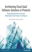
Proposed functional architecture description: The following explains the functional architecture of the solution using Figure 4.1.
- It has various functional modules: user management, content management server (CMS), event management (including ticketing), media management, doc management, Web analytics, messaging, social media, general (widgets management, accreditation).
- The platform has a website for desktop clients, and it also includes a mobile access to the same.
- Web content management (w)CMS server serves as the heart of the solution. This has both Web content database and a separate mobile content database.
- To this a listening platform, such as Radian6, is attached which fetches the customers’ comments from the open social media such as Facebook™ or Twitter™.
- Analytics functionalities are available – say custom-built sentiment analytics as well cloud service based – and helps analyse the comments of the customers and infer the overall feedback from sports enthusiasts and fans. Each stakeholder department can get analytics of their interest area.
Figure 4.1 Functional architecture with architectural building blocks derived from grouped requirements of the solution
- In addition, the solution provides a separate and exclusively created ‘enterprise social media’ for customers to chat, blog or comment or, in general, express themselves or exchange views and points among various stakeholders of this event. This can be organized to provide customer-helping-customer both during post- and pre-events. Also at the back-end, analytics can be run on this to understand the sentiments that are running about the event.
- Broadcaster service is (unlike RSS feed) to make regular announcements by the events organizers in popular pre-configured social media.
- Of course e-commerce server delivers requests from both desktop clients and mobile clients. Hence, it scales up with specific functionalities to serve as mobile-commerce (m-commerce) too.
- Payment gateway is a component that must already exist in any e-commerce solution.
- Please notice that there are specific technical software components for deducting mobile devices when the site is accessed from a mobile device. In addition, one can entertain dedicated mobile apps through a separate server.
- Please notice location services that will add ‘spice’ to mobile contents in the form of location-aware content delivery.
- In order to increase the communication mechanism – conventional SMS, FAX and email servers are included.
- In addition, the solution has envisaged various mobile applications for various groups of users and has corresponding applications for each user group.
- Video can be one of the inputs through this platform. Pre-recorded videos can come from popular video sites such as YouTube, or it can come from fans or it can be a live one too.
- Video live streaming, from archival and also from open free public external sources, is provisioned.
- Tools and platform
- COTS products such as (w)CMS server and CMS as explained in the diagram;
- .Net will be the main platform and will also be integration platform;
- Cloud-based SaaS solutions such as Radian6 and Google™ analytics;
- Some open sources to keep the cost under control such as WURFL;
- Entire infrastructure platform is on private cloud to ensure safety and security at the same time only on pay-per-use cost advantage.
- Ticket booking/ticket status reporting through mobile apps.
- ‘My interest’ feature – allows users/participants to jump into areas of his/her interest.
Customization
- Private secured cloud-based IaaS solution cost – effective, pay-as-you-go model and highly scalable hardware infrastructure.
Integration of Subsystems
- Communication including instant messaging (IM) via Smartphone (provide this feature through mobile app).
- Event promotion through broadcaster/event manager/Web channel.
- Live video streaming, Recording/Past Events Video streaming, links to open sources of video.
- Web Content Management Systems ((w)CMS) server supports multiple file formats and also allows metadata associated with these various file formats to be uploaded into (w)CMS server. (w)CMS server will need to be integrated with a video streaming server for rendering multimedia content. Graphical/animation can be easily shown from (w)CMS server in mainly three ways – through a (w)CMS server data factory Web service (basic Web service), by calling (w)CMS server pages directly that output XML/HTML data to read/render and by outputting the data directly on the page integration with social media.
- Integrated with many popular public social media.
- Solution also provides exclusive enterprise social media within the digital communication platform for various user groups to collaborate.
- Easily configurable workflow for approving contents/approving contents that need to be published in social media.
Integration with External Systems
- Listening platform is cloud-based (Radian 6), and hence is very cost effective and follows pay-as-you-go model.
- All data communication in the form of restful services enables seamless integration between cloud, mobile apps and partner’s (other vendors and stakeholders home grown) apps or systems.
4.5 Realization of the Envisaged Solution Architecture
Table 4.1 summarizes various software products (or technologies such as .Net) and meets the functional modules mentioned in previous section. (The grouping of functional capabilities can be roughly considered as architectural building blocks (ABB).)
Table 4.1 Indicates realization of envisaged architecture by indicating what functional group will be realized by (finalized or selected) software products
Features |
Realization mechanism |
Product stack |
|---|---|---|
Single sign on |
Application server |
(w)CMS server security extensions |
Personalization |
Application server |
(w)CMS server |
Authentication and authorization |
Application server |
(w)CMS server security extensions |
Policy management |
Application server |
(w)CMS server |
Report generation |
Application server |
(w)CMS server |
Session management |
Application server |
IIS |
State management |
Application server |
.Net |
Transaction management |
Application server |
IIS |
Reporting service |
Application server |
(w)CMS server, (w)CMS server logging services |
Mail framework |
Application server |
(w)CMS server, .Net |
Events and notification framework |
Application server |
(w)CMS server |
Integration with database |
Data access layer |
OLE DB |
Workflow |
(w)CMS server workflow engine |
(w)CMS server |
Note: In the above illustration, the Web server and app server are assumed to be in the same physical box.
The recommended (w)CMS Server solution comes bundled with (w)CMS Trace/Google™ analytics. The (w)CMS Server-based framework is also compatible with other Web analytics and reporting tools such as Web trends, Surf Aid and Hitbox. Raw data related to website usage and tracking is saved in log files, a bespoke reporting module can be built to review and analyse the usage of various intranets and extranets.
The use of (w)CMS Server Relate+, which offers a rich set of features (such as blogs, discussions, forums, bulletin boards, etc.), is necessary for creating social media and collaboration platform.
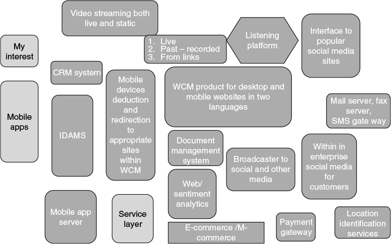
Figure 4.2 gives a pictorial view of the solution products finalized, and tabulated in Table 4.1, for each of the modules. (Reference [6] is international grade, which provides guidelines to what are all views of architecture can be provided. However, the architecture views provided, in this chapter or in the entire book, are not checked for its compliance with the benchmarks.)
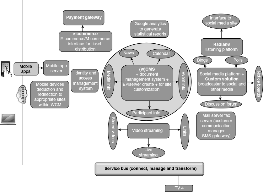
Figure 4.2 Mapping SBBs into ABBs: selection of software solution products that can match ABBs
4.6 Architectural Considerations
Description: Refer Figure 4.3 also for physical deployment architecture.
- The above view depicts the physical view of the proposed system.
- The users will be screened through the protocol firewall.
- Based on some of the non-functional requirements regarding number of concurrent users and active users, the recommended practice is to deploy all these servers as clusters in a federated environment. The server capacity may be for forecasted peak loads.
Figure 4.3 Physical deployment architecture
(For cloud IaaS, it is recommended to obtain the details of minimum configuration and the number of users or load it can handle; then as and when the load increases through an auto-scaling algorithm, additional servers will be automatically provisioned. See Chapter 7 for an illustrated explanation of this.)
For solutions such as sports events, which last for a few days, or maximum a few weeks, the organizers prefer using maximum estimated load as default hardware size.
For events such as this, it is better to go for maximum load approach; after the event, the load will drastically drop down, and hence it can be brought to highly shrinked architecture to save the cost. The same is illustrated here too. See the spreadsheet ‘capacity’ for it.
Auto-scaling is essential when the load surges beyond the estimated maximum load. Also some of the modules may face high load, depends on the features used by users, even though the overall load is well under max load for the system.
- In a federated environment (as depicted here), Web requests are routed to corresponding Web server cluster through the load balancer.
- Once user-credential validation process is successful, access to the Windows 2008 server, where IIS application server is loaded, would be available. (w)CMS server along with the extension software would be installed in this server.
- This solution would make use of mail server that will facilitate all the email-related requirements. Please note that the mail server is an open-source product.
- An FTP server is also recommended. This FTP server will be used for sharing information such as video/audio between external customer drives. In addition, this would be useful in storage of video/audio, images and document files that need to be archived in the file system instead of database.
- The SQL server database cluster will be housed in a separate Windows 2008 server across a firewall. For disaster-recovery (D-R) purposes, these clusters are typically housed inside a highly secured data centre.
In the above diagram, all servers will be in clusters under load balancers (application servers and database) will scale on demand as it is undervirtualized (private cloud or public IaaS) environment.
4.7 Mapping Deployment Architecture into Public IaaS Cloud
The steps required for this is already explained in Section 4.2.
Disclaimers
- The cost indicated are tentative and illustrative but does not reflect the actual cost taken from AWS.
- AWS itself provides a cost calculator.
- AWS of AmazonTM is used as an illustration; AWS is taken up as illustration as it also supports Windows and .Net in their IaaS infrastructure. Since the terms such as ‘large’, ‘medium’ referring to ideal server sizes are very pertinent to AWS.
Explanations for the spreadsheets:
First sheet to be studied is titled as ‘topology’: This explains how a virtual private cloud is created within public IaaS; and the same is accessed from a remote developer LAN for developing and dumping the developed or maintained code into the IaaS.
The diagram did not show how users would access the system; it is through cloud from their devices.
Second sheet to be studied is titled ‘availability’: This indicates for how long the individual servers are required for the project.
- Some of the servers are required for development purposes; therefore, they need to be available well ahead of the event date.
- Some of them are required only during and post-event period.
- This sort of information should be collected during system study and development.
- The availability information is carried into cost calculation in next sheet to be studied and titled ‘IaaS cost calculation’.
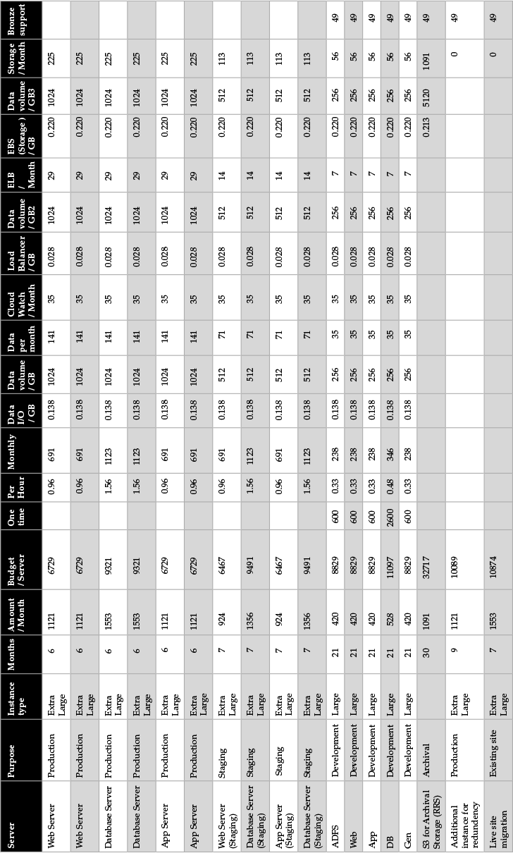
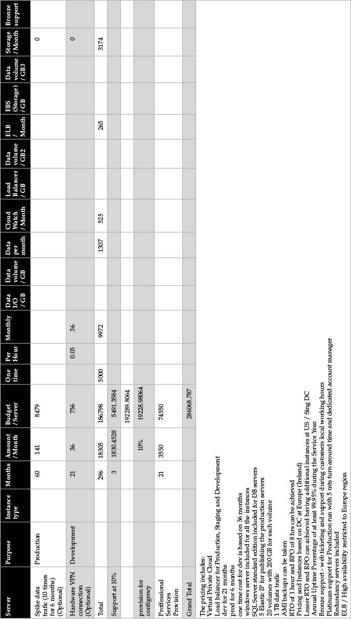
Third sheet to be studied is ‘IaaS cost calculation’:
- This is the sheet where deployment servers are mapped on to IaaS ideal server sizes (see Table 4.1).
- This sheet also gives the operating system or other infrastructures that are required for each server and hence, each corresponding instance in the IaaS. The cost of infrastructure software is also usually on pay-per-use model from IaaS providers.
- There is a fixed one-time cost and there is a pay-per-use cost.
- The cost indicated here is an estimated cost and not actual cost; actual cost will be pay-per-use plus the one-time cost.
- Readers ’ attention is drawn to the details one needs to have as estimate before calculating the cost; these details are data storage requirement, bandwidth requirements, etc.
4.8 Summary
- The main objective of this chapter is to illustrate how to arrive at a deployment architecture suitable to map a public IaaS.
- In addition, this chapter provided details of mapping a deployment architecture to public IaaS.
- One can also learn how to move from requirements to ABBs and then to identify corresponding SBBs.
- A detailed calculation of cost of IaaS is provided.