Chapter 3: Operating in Real Time
This chapter addresses the need for embedded systems to generate real-time responses to inputs from sensors and other sources. The concepts of Real-Time Operating Systems (RTOSes) and their key features are introduced, as well as some challenges that commonly occur when implementing multitasking real-time applications. The chapter concludes with a discussion of the important characteristics of some popular open source and commercial RTOS implementations.
After completing this chapter, you will understand what it means for a system to operate in real time and will know the key attributes a real-time system must exhibit. You will understand the RTOS features that embedded systems rely upon, as well as some problems that frequently crop up in real-time embedded system designs. You will also have learned the key features of several popular RTOS implementations.
We will cover the following topics in this chapter:
- What does real-time mean?
- Attributes of a real-time embedded system
- Understanding key RTOS features and challenges
- Popular RTOSes
Technical requirements
The files for this chapter are available at https://github.com/PacktPublishing/Architecting-High-Performance-Embedded-Systems.
What does real-time mean?
Real-time means computing with a deadline. In a real-time embedded system, the time it takes to respond to an input is a critical component of system performance. If the system produces a correct response, but the response is not generated within the required time limit, the effect may range from a mild nuisance to a catastrophic impact for a safety-related system.
The response of a real-time embedded system to inputs must be both correct and timely. Most standard software development approaches focus on the correctness of the response produced by a piece of code rather than being overly concerned with the timeliness of the response. Non-real-time software development approaches attempt to develop code that executes as quickly as possible, but usually do not provide a hard time limit specifying when the response must be provided. Real-time systems are considered to have failed if the timing constraints are not met, even during stressing and rare combinations of operating conditions. A computing system that produces the intended outputs is considered functionally correct. A system that produces outputs within specified time limits is considered temporally correct. Real-time systems must be both functionally and temporally correct.
Consider two automotive embedded subsystems: the digital key fob used to unlock the car door and the airbag control system. If the key fob takes a few seconds longer for the car door to unlock than expected, the user may be a bit irritated, but will still be able get into the car and operate it. But, if the airbag controller were to take a fraction of a second longer to respond than expected in a serious collision, the result may be passenger fatalities.
Real-time applications can be divided into two categories: soft real-time and hard real-time. Systems in which real-time behavior, defined as the ability to meet all of the system's timing requirements, is highly desired but not absolutely necessary are called soft real-time systems. The automotive key fob response time is an example of this category. While undesired delays in response may have negative impacts, such as reducing the level of perceived product quality in users' minds, the system nevertheless remains functional and usable. Real-time systems that must, under all circumstances, strictly meet all of their timing requirements, such as the airbag controller, are considered hard real-time systems.
The process used to develop and test software for embedded applications must maintain a continuous focus on the system's real-time requirements and ensure the software implementation does not compromise performance in terms of those requirements. For example, if noisy sensor measurements require digital filtering to reduce the effects of the noise, the code to implement the filtering will most likely require the insertion of loops in the code to implement the algorithm. The addition of loops, particularly if they iterate a large number of times, can substantially increase code execution time and possibly violate timing requirements.
The next section will examine the key attributes a real-time embedded system must possess, including the necessary features of the processor hardware, I/O devices, and operating system-level software.
Attributes of a real-time embedded system
The hardware and software of a real-time embedded system must exhibit some specific characteristics to ensure the system reliably meets its performance goals of producing reliably correct and timely outputs. Most real-time embedded systems that perform functions of moderate to high complexity must divide the processing work into multiple tasks that execute in an apparently (to the user) simultaneous manner, including managing the operation of hardware such as an automobile engine while regularly updating information displayed to the driver.
At the finest-grained level of processor operation, most embedded systems rely on the use of interrupts to notify the processor when an operation is required by an I/O device. In a real-time application, the handling of interrupts can become a critical factor in ensuring proper system operation. At the simplest level, any time an interrupt is being processed, the code algorithm that was paused to handle the interrupt is blocked from execution. This means that when the paused code resumes execution, it will have less time to complete before its deadline arrives. As a rule of thumb, it is best to minimize the amount of time spent handling interrupts.
Related to interrupt processing, the time-related performance of I/O devices is another important factor in the performance of real-time applications. Some I/O devices, such as a flash memory card, may require a substantial length of time to complete a read or write operation. When working with these devices, it is not acceptable for the processor to stop and simply wait for the operation to complete. Similarly, an ADC takes some time to perform the analog-to-digital conversion operation. If the processor spins on the conversion complete status bit, waiting for the conversion to finish, the delay may again be unacceptable. More sophisticated techniques are required when working with these devices.
The following sections discuss these system concerns and the important real-time performance attributes associated with each of them.
Performing multiple tasks
It is common for an embedded system to appear to be performing multiple tasks simultaneously. It is normally not necessary for the system to perform multiple different functions at the same precise point in time. Instead, it is generally acceptable to rapidly switch from performing one task, to the next, and so on. If each task succeeds at updating at its intended rate, it does not matter whether the system performs other actions between those updates.
It is also common for the various tasks a system performs to require updates at different rates. For example, a system that controls the speed of a vehicle electric drive motor may need to update the outputs that control the motor dozens of times per second, while the same device updates status information displayed to the user just a few times per second.
It is certainly possible for a developer to combine the code to perform both of these tasks (motor control and status display) with code that manages the execution of each task at appropriate time intervals, all within a single module. However, this is not an ideal approach. It is conceptually simpler to break the application code for each task into a logically separate module and manage the scheduling of the tasks from a higher-level module.
To provide a concrete example, assume we need to update an electric motor control task at a 50 Hz rate and update the user status display at a 10 Hz rate. We will also assume the longest possible time it takes the motor control code to run is 5 ms and the user status display code takes up to 10 ms to run, due to the need to transfer data over a slow interface. If we reach a point where both tasks are ready to run, we must ensure the motor control task receives the highest priority because we need the motor updates to execute at precise time intervals. Updating the status display is lower priority because if the timing of updates to the status display varies by a few milliseconds, it will not be noticeable to the user. In this example, the motor control task has a hard real-time requirement, while the status display task is a soft real-time function.
The following C language listing is an example of a control program that initializes the system, and then executes a loop at 20 ms intervals, updating the motor control on each pass. Every fifth pass through the loop, it also updates the status display after completing the motor control update. In this code, the WaitFor20msTimer function may be implemented as an interrupt-driven function that places the processor in a low power sleep state while waiting for the timer interrupt to wake it.
Alternatively, WaitFor20msTimer may contain a simple loop that reads a hardware timer register until the timer reaches the next 20 ms increment, at which point it returns:
void InitializeSystem(void);
void UpdateMotorControl(void);
void UpdateStatusDisplay(void);
int main()
{
InitializeSystem();
int pass_count = 0;
const int status_display_interval = 5;
for (;;)
{
WaitFor20msTimer();
UpdateMotorControl();
++pass_count;
if (pass_count == 1)
{
UpdateStatusDisplay();
}
else if (pass_count == status_display_interval)
{
pass_count = 0;
}
}
return 0;
}
This code executes in the pattern shown in Figure 3.1. The Motor Control code executes for 5 ms at 20 ms intervals, represented by the pulses in the upper graph. After the first Motor Control update completes, the control loop calls the Status Display update routine at time A. The dashed line in the diagram shows this relationship between the end of motor update processing and the start of Status Display update processing, which appears in the lower graph:
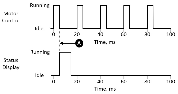
Figure 3.1 – Embedded system control loop timing
This code will be guaranteed to meet its timing requirements for Motor Control updates and Status Display updates as long as the processing time for each of the update routines remains within its constraints. There will be some small amount of timing jitter on the Status Display updates because the Status Display routine begins after the Motor Control update ends, and there is no guarantee that the time the Motor Control code takes to execute will be identical each time it runs.
What happens, though, if the Status Display code is upgraded to pass additional information to the display and the new version takes 20 ms to execute instead of 10 ms, as in the original version? From Figure 3.1, we can see that execution of the Status Display update will stretch 5 ms into the time period intended for the Motor Control update, delaying its execution. We have already determined that this sort of delay is unacceptable. What can we do to resolve this problem?
One possible approach is to split the Status Display update code into two separate routines, each taking no more than 10 ms to execute. These routines can be called in sequence, as shown in Figure 3.2:
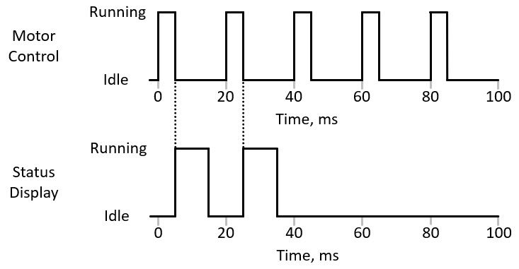
Figure 3.2 – Status update split into two parts
This solution will continue to meet all of the timing performance requirements, as long as each stage of the status update code finishes execution within its 10 ms time limit. The following code listing implements this solution:
void InitializeSystem(void);
void WaitFor20msTimer(void);
void UpdateMotorControl(void);
void UpdateStatusDisplay1(void);
void UpdateStatusDisplay2(void);
int main()
{
InitializeSystem();
int pass_count = 0;
const int status_display_interval = 5;
for (;;)
{
WaitFor20msTimer();
UpdateMotorControl();
++pass_count;
if (pass_count == 1)
{
UpdateStatusDisplay1();
}
else if (pass_count == 2)
{
UpdateStatusDisplay2();
}
else if (pass_count == status_display_interval)
{
pass_count = 0;
}
}
return 0;
}
In this version of the application, the Status Display code is broken down into two functions: UpdateStatusDisplay1() and UpdateStatusDisplay2().
While this solution is workable in terms of meeting the timing requirements for the system, it is far from an ideal approach. For one thing, it may not be easy, or even possible, to separate the Status Display update code into two functions, each taking approximately the same length of time to execute. Ongoing maintenance becomes more of a problem when changes must be made to this code. In addition to ensuring the new code is functionally correct, it must be distributed between the two update functions to ensure neither exceeds its execution time limit. This is, frankly, a brittle solution.
For a real-time embedded system design, this approach is clearly inappropriate. Much of the complexity in this example can be avoided through the use of preemptive multitasking. Preemptive multitasking is the ability of a computer system to pause and resume the execution of multiple tasks as needed based on scheduling criteria.
Popular desktop operating systems such as Microsoft Windows and Linux perform preemptive multitasking to allow dozens or even hundreds of simultaneously executing processes to share processor time in a manner that allows all of them to perform their work.
An embedded operating system supporting preemptive multitasking follows a few simple rules to determine which of potentially several tasks is permitted to run each time it performs a scheduling operation.
In embedded systems, a task is a distinct thread of execution with a set of associated resources, including processor register contents, a stack, and memory. In a single-processor computer, only one task can be executing at any given time. A scheduling event allows the system to select the next task to run and then start or resume its execution. Scheduling events include timer events and task transitions to a blocked state, as well as operating system calls invoked from application code and from Interrupt Service Routines (ISRs).
Tasks in embedded systems are usually in one of three states:
- Ready state: The task is prepared to run but it is not actually running because it is in the scheduler's queue awaiting scheduling for execution.
- Running state: The task is executing processor instructions.
- Blocked state: The task is waiting for an event to occur, such as waiting for a system resource or for the receipt of a signal from a timer.
Each task is assigned a priority by the system developer. Each time a scheduling event occurs, the system identifies the highest priority task that is in either the Ready or Running states and transfers control to that task, or leaves it in the Running state if it is already there. The switch from one task to another involves storing the context information, primarily the processor register contents, associated with the departing task in its Task Control Block (TCB) and restoring TCB information for the incoming task to the processor registers before jumping to the next instruction in the incoming task's code. Each context switch takes a small amount of time that subtracts from the time available for task execution.
Figure 3.3 presents the operation of the Motor Control algorithm within a preemptive multitasking RTOS. This system has timer events at 20 ms intervals. At each interval, the Motor Control task enters the Ready state and, because it has the higher priority, it immediately enters the Running state and executes its update, and then returns to the Blocked state:

Figure 3.3 – Preemptive multitasking
Every 100 ms, the Status Display task enters the Ready state, but because it is lower priority, the Motor Control task runs first. When the Motor Control task enters the blocked state at time A, the Status Display task enters the Running state and begins execution. At 20 ms, another timer event occurs and the Motor Control task again enters the Ready state. Because it is higher priority, it again runs until it enters the Blocked state. At that point, the Status Display task resumes execution until it completes its update and enters the Blocked state.
The following listing shows an implementation of this system in C using the FreeRTOS RTOS:
#include "FreeRTOS.h"
#include "task.h"
void InitializeSystem(void);
void UpdateMotorControl(void);
void UpdateStatusDisplay(void);
static void StatusDisplayTask(void* parameters)
{
TickType_t next_wake_time = xTaskGetTickCount();
for (;;)
{
const TickType_t block_time = pdMS_TO_TICKS(100);
vTaskDelayUntil(&next_wake_time, block_time);
UpdateStatusDisplay();
}
}
static void MotorControlTask(void* parameters)
{
TickType_t next_wake_time = xTaskGetTickCount();
for (;;)
{
const TickType_t block_time = pdMS_TO_TICKS(20);
vTaskDelayUntil(&next_wake_time, block_time);
UpdateMotorControl();
}
}
void main(void)
{
xTaskCreate(StatusDisplayTask, "StatusDisplay",
configMINIMAL_STACK_SIZE,
NULL, (tskIDLE_PRIORITY + 1), NULL);
xTaskCreate(MotorControlTask, "MotorControl",
configMINIMAL_STACK_SIZE, NULL,
(tskIDLE_PRIORITY + 2), NULL);
InitializeSystem();
vTaskStartScheduler();
// This point is only reached if memory
// allocation fails during startup
for (;;);
}
This code defines two tasks as C functions: StatusDisplayTask() and MotorControlTask(). The same functions that implement the application functionality in the earlier example are used here: InitializeSystem(), UpdateStatusDisplay(), and UpdateMotorControl(). The vTaskDelayUntil() function performs a precise time delay to ensure the Motor Control task becomes ready to run every 20 ms and the Status Display task becomes ready to run every 100 ms.
Task priorities in FreeRTOS are assigned with lower numerical values representing lower priorities. The lowest priority is the idle task with a priority of 0, represented by the constant tskIDLE_PRIORITY. The idle task is provided by the system and executes whenever a scheduling event occurs and there is no other task in the Ready state. The Status Display task is assigned a priority one higher than the idle task and the Motor Control task is assigned a priority two higher than the idle task.
This example should make it clear that the use of preemptive multitasking takes a great deal of work off the shoulders of the system developers when working with multiple real-time tasks executing at different update rates. Although this example included only two tasks, the principles of task prioritization and preemptive multitasking support an arbitrary number of tasks in a system, limited only by available system resources and execution time constraints.
While preemptive multitasking relieves system developers from the need to fit code execution within narrow time slots, there is still a limit to how much execution time each task in a multitasking system can consume and remain guaranteed to meet its timing constraints. The next section introduces rate-monotonic scheduling, which provides a method to guarantee that timing constraints will not be violated as long as certain conditions are met.
Rate-monotonic scheduling
The processor utilization of a periodic task is the maximum execution time of the task divided by the execution interval of the task, expressed as a percentage. In our example, with the extended Status Display processing time, the utilization of the Motor Control task is (5 ms / 20 ms) = 20%, and the utilization of the Status Display task is (20 ms / 100 ms) = 20%. The total processor utilization for this application is thus 20% + 20% = 40%.
While we can be confident that our two-task system represented in Figure 3.3 will always satisfy its timing constraints, how can we retain this confidence if we add more tasks to the system, each updating at its own rate, and each with its own processor utilization?
Rate-monotonic Scheduling (RMS) provides an answer to this concern. The timing constraints of a real-time system with periodically scheduled tasks are guaranteed to be met if the following conditions and assumptions are satisfied:
- Task priorities are assigned with the highest priority going to the most frequently executing task, decreasing monotonically down to the lowest priority assigned to the least frequently executing task.
- A task cannot block waiting for a response from another task.
- The time to perform task scheduling and context switching is considered negligible.
- The total processor utilization (the sum of the processor utilizations for all
 tasks) is no greater than
  .
.
The following table employs this formula to present the RMS processor utilization limits for task counts from 1 to 8:

In our example, the total processor utilization was 40%. From the preceding table, we see that we can increase the processor utilization as high as 82.84% with two tasks and still be guaranteed that timing constraints will be satisfied, as long as the RMS criteria are satisfied.
As the number of tasks in a system increases, the maximum processor utilization decreases. As the number of tasks becomes very large, the maximum processor utilization converges to a limit of 69.32%.
The RMS limit on processor utilization is conservative. It may be possible for a system to run at a higher level of processor utilization for a particular number of tasks than is shown in this table.
In addition to preemptive multitasking, most popular RTOS implementations support a variety of standard features, while also requiring developers to remain aware of certain potential problem areas. The next section introduces some standard RTOS capabilities and areas of concern for system architects.
Understanding key RTOS features and challenges
Several standard capabilities are included in most of the RTOS implementations that are in wide use today. Some of these features enable efficient communication among tasks in a manner consistent with real-time operation. While common, not all of the following features are universally available in all RTOSes.
Mutexes
A mutex, which stands for mutual exclusion, is a mechanism for managing access to a shared resource among tasks. A mutex is conceptually identical to a global variable that can be read and written by all tasks. The variable has the value 1 when the shared resource is free, and 0 when it is in use by a task. When a task needs to gain access to the resource, it reads the variable and, if it is free, with the value 1, sets it to 0 to indicate the mutex is owned by a task. The task is then free to interact with the resource. When the interaction is complete, the task sets the mutex to 1, thereby releasing ownership.
If a task attempts to take ownership of the mutex while the mutex is held by another task, the first task will block until ownership is released by the second task. This remains true even if the task holding the mutex has a lower priority than the task requesting it. Figure 3.4 presents an example of how mutex ownership can interact with task priorities:

Figure 3.4 – Mutex ownership interaction with task priorities
This diagram shows the two tasks running in the preemptive multitasking environment of Figure 3.3, except in this case, the Status Display task takes ownership of a mutex at time A. At time 20 ms, the Motor Control task becomes scheduled and begins executing. Midway through processing, at time B, the task attempts to take the same mutex, but because the resource is not available, the Motor Control task blocks. This allows the Status Display task to resume processing until it frees the mutex at time C. This unblocks the Motor Control task, allowing it to take the mutex and resume execution. The Motor Control runs until it completes its update, and then blocks, waiting for the next cycle. The Status Display task then resumes until it, too, blocks, waiting for its next update.
In this example, the blocking of the Motor Control task resulted in a delay in the completion of its processing, which we have already indicated is unacceptable in the system design. We must also note that this violated one of the RMS criteria, specifically, the admonishment to avoid execution dependencies between tasks. Introducing such complexities does not mean the system will not be able to work properly; it simply means additional analysis and testing will be required to ensure proper system operation under all conditions.
This example demonstrates some of the complexity and pitfalls you may encounter when working with inter-task dependencies. A good rule of thumb when working with mutexes is to hold the mutex for the smallest possible length of time before releasing it.
Semaphores
A semaphore is a signaling mechanism that synchronizes operations across tasks. The semaphore is a generalization of the mutex and can be of two types: a binary semaphore or a counting semaphore. A binary semaphore functions similar to a mutex, except its purpose is to send a signal to another task. If a task attempts to take a semaphore while it is held by another task, the requesting task will block until the task holding the semaphore gives it.
A counting semaphore contains a counter initialized to an upper limit. Each time a task takes a counting semaphore, the counter decrements by one. When the counter reaches zero, attempts to take the semaphore will block until at least one semaphore holder gives it, which increments the counter.
One application of a semaphore involves the reception and processing of incoming data. If the I/O device associated with the incoming data stream uses a processor interrupt to trigger an ISR, the ISR can retrieve the data from the peripheral device, store it in a memory buffer, and give a semaphore that unblocks a task waiting for incoming data. This design approach allows the ISR to exit as quickly as possible, making the system more responsive to subsequent interrupts and minimizing delays in task execution.
It is generally advisable to spend as little time as possible processing each ISR, which means handing off processing duties to a task via a semaphore is an effective way to reduce the latency of subsequent interrupts. When the task finishes processing the incoming data, it again attempts to take the semaphore, which will block if no additional data has arrived since the last time it took the semaphore.
Queues
A queue, sometimes called a message queue, is a one-way communication path between tasks. A sending task places data items in the queue and the receiving task removes them in the same order they were inserted. If the receiver attempts to read a queue that is empty, it can choose to block while waiting for data to be placed in the queue.
Similarly, if the queue is full and the sender attempts to place data in the queue, it can choose to block until there is space available. Queues are commonly implemented using a fixed-size memory buffer that can contain an integer number of fixed-size data items.
Event flags
Event flags, also known as event groups, are collections of single-bit flags that signal the occurrence of events to tasks. Event flags support a wider range of inter-task communication signaling methods than semaphores. Features of event flags include the following:
- A task can block waiting for a combination of event flags. The task will only become unblocked when all of the events indicated by the selected flags have occurred.
- Multiple tasks can block waiting on a single event flag. When the event occurs, all of the waiting tasks are unblocked. This differs from the behavior of semaphores and queues, which only unblock a single task when the event occurs.
Event flags are useful in specific situations, such as broadcasting a notification that must be received by multiple tasks, or waiting for a combination of activities performed by different tasks to complete.
Timers
Timers provide a different method of scheduling future events than the task scheduling mechanism previously discussed. A timer provides a means for scheduling a call to a function at a specified time in the future. The function to be called at that time is an ordinary C language function specified by the developer. This function is identified as the timer callback function.
The call to the timer callback function takes place in the context of a system-provided task that obeys the regular rules of task scheduling. In other words, the timer callback function will only be called if, when the specified time arrives, the system task in control of timer function calls is the highest priority task that is ready to run. If a higher-priority task is executing at that time, the call to the timer callback function will be delayed until the higher-priority task blocks. The system developer has the ability to specify the priority of the timer callback scheduling task.
Timers can be configured in one-shot mode or repetitive mode. In one-shot mode, the timer callback function is executed one time after the delay expires. In repetitive mode, the timer callback function executes periodically with a period equal to the timer delay.
Dynamic memory allocation
Like desktop computer operating systems, RTOSes generally provide mechanisms to allocate and release blocks of memory. Consider a word processing program running under Windows or Linux. When the user opens a document file from disk, the program determines the amount of memory needed to hold the entire document, or at least part of it, and requests that amount of memory from the operating system. The program then reads the contents of the document into the newly allocated memory region and allows the user to work with it. As the user edits the document, more memory may be needed to hold additional content. The word processor sends additional allocation requests to the operating system when needed to maintain sufficient space to hold the document content. When the user closes the document, the program writes the updated document to disk and releases the memory it was using for the document data.
Similar actions take place in embedded systems, though instead of working with word processor documents, the system is usually working with sensor input such as temperature measurements, button presses, or streams of audio or video data. For some real-time embedded applications, it makes sense to perform dynamic memory allocation as part of routine system operation. There are, however, some well-known problems that can arise in embedded applications that use dynamic memory allocation.
The C language is widely used in embedded system development. This programming language does not provide automatic allocation and deallocation of memory as objects and data structures are created and destroyed. It is up to the system developer to ensure that the allocation and freeing of memory takes place in a correct, efficient, and reliable manner.
Memory leaks and fragmentation are two types of problems that tend to cause issues when using dynamic memory allocation in real-time embedded systems.
Memory leaks
If the system repetitively performs memory allocation, perhaps to temporarily store blocks of incoming data, the system must eventually release the memory to ensure there will be space available for future incoming data.
The region of system memory used for dynamic allocation is called the heap. If allocated memory is not released in a timely manner, the available heap space will eventually become exhausted. If the operation of freeing each memory block after use is either mistakenly left out of the code or bypassed for some reason, or if the memory blocks are retained for such a long time that the available memory is reduced to zero, a heap overflow will occur. In this situation, additional attempts to allocate memory will fail.
We can expect the system to crash or exhibit other forms of unintended behavior if a heap overflow occurs in the absence of effective steps to detect the overflow and correct the situation. In the C language, a call to the malloc() memory allocation function returns the special value NULL when it is unable to allocate the requested size block of memory.
Tutorial examples you may come across demonstrating the use of malloc() often assume the call always succeeds, and immediately begin using the return value as a pointer to the freshly allocated block. When malloc() fails to allocate the requested block of memory, the return value of NULL is, in effect, an address of zero. In a desktop operating system, any attempt to read or write memory at the address zero results in a memory access violation and, normally, the program exits with an error message.
In an embedded system, depending on the particular hardware architecture, it may be perfectly acceptable to read and write address zero. These low addresses usually contain important processor registers, and writing arbitrary data to them (because the code assumed malloc() returned a valid pointer to a memory block but it received zero instead) is likely to cause the system to abruptly stop operating correctly. Because this type of error occurs only after the system has been running long enough to consume all available memory, it may be very difficult to identify and debug the source of the problem.
Heap fragmentation
If a real-time application performs dynamic memory allocation, it is possible for the response time performance to be perfectly adequate at system startup and for some time thereafter, but degrade over time. If frequent memory allocation and free operations take place during system operation, even if there is no heap overflow, it is possible, and even likely, that the managed memory region will become fragmented into free blocks of various sizes. When this happens, a memory allocation for a large block might not be immediately possible even though plenty of free memory is available. The memory manager will have to consolidate some number of smaller free blocks into a single block that can be returned for use by the calling code.
In a highly fragmented memory scenario, the process of consolidating multiple blocks can take a long time, which may lead to failure of the system to meet its timing deadlines. Bugs such as this (and it is a bug, even though the system eventually performs in a functionally correct manner) might occur rarely, with serious effects on system behavior, and are often difficult to replicate in a debugging environment.
Deadlock
When using mutexes to manage access to multiple shared resources, it is possible to encounter situations where multiple tasks attempt to take more than one semaphore each and enter a situation where the tasks become permanently blocked. This is called deadlock.
For example, assume the Motor Control and Status Display tasks have access to mutexes associated with shared system resources. Assume mutex Mdata controls access to a data structure shared among tasks and mutex Mconsole controls access to the output channel for writing console messages. Figure 3.5 presents the timeline for this scenario:

Figure 3.5 – Deadlock example
During its execution, the Status Display task is preparing to write a message to the console. The Status Display task has taken Mconsole at time A and is formatting the message to be displayed. The task is interrupted to schedule the higher-priority Motor Control task at the 20 ms mark.
During its processing, the Motor Control task takes Mdata at time B and begins working with the data structure. While working with the structure, it detects an out-of-limits condition within the data and determines it must write a message to the console describing the condition. The Motor Control task then attempts to take Mconsole at time C so it can write the message.
Since the Status Display task already has ownership of the Mconsole mutex, the Motor Control task blocks and the Status Display task resumes execution, preparing its own message for display on the console. To populate the message, the Status Display task must gather some information from the shared data structure, so it attempts to take Mdata at time D.
At this point, both of the tasks are stuck, with no way out. Each task has taken one of the two mutexes and is waiting for the other mutex to become free, which cannot happen because both tasks are blocked.
In this example, the actions taken by each task, viewed in isolation, appear reasonable, but when they interact through the mutexes, the result is an immediate halt to system operation, at least for the affected pair of tasks. This represents a catastrophic failure in terms of system performance.
Avoiding the possibility of deadlock is a responsibility of the system architect. There are a couple of rules of thumb that will ensure deadlock cannot occur in a system design:
- Whenever possible, avoid locking more than one mutex at a time.
- If you must lock multiple mutexes in multiple tasks, ensure they are locked in the same sequence in each task.
Some RTOS implementations can detect the occurrence of a deadlock and return an error code when attempting to take a semaphore that would result in deadlock. The algorithm required to implement this capability is considered expensive in terms of embedded resources (specifically, code size and execution time), and avoiding the possibility of deadlock through careful system design is often the superior approach.
Priority inversion
A situation that causes a violation of task prioritization can occur when tasks of varying priorities use a mutex to control access to a shared resource. This situation can occur with three tasks of different priorities.
Let's add another task to our system for performing measurements with an ultrasonic sensor. This task runs at 50 ms intervals and takes up to 15 ms to complete each execution cycle. To comply with the requirements of RMS, this task must have a priority between those of the Motor Control task, which runs at 20 ms intervals, and the Status Display task, which runs at 100 ms intervals.
We can quickly check whether the system remains schedulable under the RMS criteria. In the Rate-monotonic scheduling section, we saw that the total processor utilization for the two-task application is 40%. The new task consumes another (15 ms / 50 ms) = 30% of processor time, for a combined total utilization of 70%. From the table in the Rate-monotonic scheduling section, we see that the RMS schedulability threshold for a three-task system is 77.98%. Because our processor utilization is below the threshold, we can be certain that as long as the RMS criteria are met, the system will meet timing deadlines.
Let's say the new Sensor Input task is first scheduled at time 10 ms and again at 60 ms. Because the Motor Control task is also scheduled at 60 ms, the Sensor Input update must block until the Motor Control task update is complete. We will assume that this deviation from precise periodic update intervals is not a significant issue for the application. This execution timing sequence is shown in Figure 3.6:
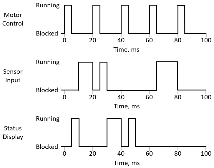
Figure 3.6 – Three-task execution sequence
The Status Display task update is now broken into three separate execution time segments. While this may appear unusual, such behavior is perfectly normal in a preemptive multitasking system.
Let's introduce an innocuous-seeming dependency between the Status Display task and the Motor Control task. We learned from our problematic implementation of mutex usage in Figure 3.4 that we need to limit the length of time a mutex is held by a lower-priority task to the absolute minimum. In the three-task system, the Status Display task now only holds the mutex protecting the shared data structure long enough to copy the data it needs before releasing the mutex. We expect this to substantially reduce, though not entirely eliminate, the unacceptable Motor Control task execution delay of Figure 3.4.
Unfortunately, when we run the system, we see the timing response is occasionally much worse, as shown in Figure 3.7:
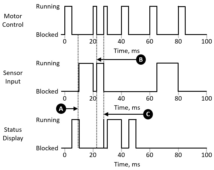
Figure 3.7 – Priority inversion example
What's happening here? At time A, the Status Display task takes the mutex. Even though it intends to release it very shortly, the Sensor Input task becomes ready to run and begins execution before the Status Display task can release the mutex. At time 20 ms, the Motor Control task is scheduled and begins execution.
At time B, the Motor Control task attempts to take the mutex, which causes it to block. The Sensor Input task is ready to run, so it resumes execution at this point. It is not until the Sensor Input task finishes its update and blocks that the Status Display task becomes ready to run again, at time C. When the Status Display task resumes, it quickly finishes reading the data structure and releases the mutex. This finally allows the Motor Control task to take the mutex and finish its (much delayed) execution.
The problem here was that the mid-priority task (Sensor Input) was able to run even though the higher-priority task (Motor Control) would have been ready to run had the low priority task (Status Display) been allowed to continue execution and release the mutex. This situation is called priority inversion.
The standard RTOS solution to the priority inversion problem is to implement priority inheritance. In priority inheritance, whenever a higher-priority task blocks waiting for the release of a resource held by a lower-priority task, the lower-priority task temporarily raises its priority to that of the higher-priority task. Once the resource has been freed by the lower-priority task, that task returns to its original priority.
Figure 3.8 shows the same situation as Figure 3.7, except priority inheritance is now implemented:

Figure 3.8 – Priority inheritance
In this diagram, the Status Display task again takes the mutex at time A. At time B, the Motor Control task attempts to take the mutex. The system elevates the priority of the Status Display task to that of the Motor Control task, ensuring the Sensor Input task does not run. This give the Status Display task an opportunity to quickly complete reading the structure and release the mutex. The Motor Control execution timeliness is now significantly improved in comparison to Figure 3.7.
The next section briefly introduces some popular RTOSes and highlights their features and the categories of real-time embedded applications best suited to each of them.
Popular real-time operating systems
When selecting an RTOS for a particular real-time embedded system architecture and application domain, it is important to consider a variety of technical and non-technical factors in the selection process. Almost all popular RTOSes support prioritized preemptive multitasking, mutexes, semaphores, queues, event flags, timers, and dynamic memory allocation. All of the RTOSes listed in this section include these features.
Some key technical attributes that differentiate among the various RTOSes are as follows:
- Feature richness: Some RTOSes are intended be as small as possible, consuming the absolute minimum quantity of ROM, RAM, and processor cycles in tiny microcontrollers. Other RTOSes are designed to support a large number of tasks and complex protocol stacks such as TCP/IP running on a 32-bit processor.
- Memory protection and virtual memory management: Simple microcontrollers and low-end microprocessors typically support only direct physical addressing of ROM and RAM. Many mid-range processors provide a mechanism for controlling memory access called a Memory Protection Unit (MPU). With the use of MPU functionality, memory regions can be isolated and protected to ensure critical system functions continue running even if less critical tasks experience problems that cause them to erroneously access memory and, perhaps, crash. At a more sophisticated level, 32-bit processors often include a Memory Management Unit (MMU), providing each running process with its own protected virtual address space. RTOSes supporting virtual memory take advantage of MMU hardware to encapsulate each process (which is conceptually similar to a task) in its own dedicated memory region so that tasks cannot interact with each other, intentionally or otherwise, except through system-provided communication channels.
- Modularity and configurability: Adding features to an RTOS increases the amount of ROM required for code and RAM required for data. Most RTOSes provide configuration options to include only those features that an application actually needs in the compiled memory image, reducing the amount of memory and processing time required.
- Processor architecture support: RTOSes generally come with a list of processor architectures and specific processor models supported by the implementation. These processor-specific implementations generally come with a code library called a Board Support Package (BSP). A BSP includes an implementation of the RTOS tailored to a specific processor model and, often, to a particular circuit board and its I/O interfaces. The BSP also includes a library of device drivers that enables the system developer to begin implementing an application using a standard programming interface to the processor hardware. If you have already selected a processor architecture for your application, this will constrain which RTOSes are suitable for your use.
- Supporting tools and accessories: In addition to the core RTOS and associated device drivers, you may require additional hardware and software tools to support the development process, such as debuggers, execution tracers, timing analyzers, and memory usage analyzers. Support for such tools varies among the available RTOSes.
Some non-technical attributes that you may wish to consider during RTOS selection are as follows:
- Choosing commercial or open source: Paying a license fee for a commercial RTOS provides some significant benefits, including technical support and some promise of future RTOS sustainment. Of course, it also costs money. There are many free-to-use RTOS implementations available as well, but each comes with its own licensing requirements, community of users, and prospects for future support.
- Vendor lock: Once you implement your application using a particular RTOS, you are, to some degree, committed to continued use of that RTOS. If the commercial RTOS vendor you select goes out of business or changes its licensing terms in an undesirable manner, or if the open source RTOS you choose falls out of favor and becomes unmaintained, you may have to make a choice to perform a potentially painful re-architecting of your design.
- Formal certification: For safety-critical applications, such as in aircraft, automobiles, and medical devices, some RTOSes have received formal certification as suitable for use in those contexts. If you are building a system where such a certification is important, this will focus you search on the RTOSes that have achieved the appropriate certification.
- Software license terms: A license for a commercial RTOS contains whatever terms the vendor chooses to put in their license agreement. Open source RTOSes are commonly licensed under one of the MIT, Apache, or GPL licenses. The MIT and Apache licenses are considered permissive, meaning developers can take the software and use it for their own purposes, including commercial applications, without being compelled to make their own source code public. The GPL, on the other hand, requires developers who incorporate GPL code into a product they distribute to make their code available to all who request it. This is obviously a highly simplified description of the distinction between these licenses. Many factors can combine to make licensing issues for products based on open source code extremely complex.
The following sections briefly describe a number of popular RTOSes and highlight the unique features of each. The RTOSes are listed in alphabetical order to avoid implying a preference for any particular one. This list is not intended to be exhaustive.
embOS
embOS is a commercial RTOS produced by SEGGER Microcontroller LLC. embOS is intended for use across a wide range of real-time applications, from single-chip, battery-powered devices to sophisticated systems running on advanced processors. embOS supports virtually all embedded processor architectures from major vendors as well as a wide variety of compilers for those architectures.
An edition of embOS is available with full MPU support. A separate edition is safety certified to the IEC 61508 SIL 3 standard, which certifies a safety-focused RTOS software development process, and IEC 62304 Class C, which represents suitability for use in medical device applications.
A free version of embOS is available for non-commercial use. This version does not include embOS source code. For commercial use, or to receive source code, you must purchase a license. See https://www.segger.com/products/rtos/embos/ for more information.
FreeRTOS
FreeRTOS is a free RTOS microkernel developed by Real Time Engineers Ltd. A microkernel contains a minimal amount of code that implements the basic functionality of an RTOS, including task management and inter-task communication.
FreeRTOS provides several options for dynamic memory management, from no memory allocation capability at all to support for the unrestricted allocation and freeing of arbitrarily sized memory blocks. FreeRTOS supports 35 different microcontroller platforms and is written in the C language with a few assembly language functions to support preemptive multitasking.
Amazon maintains an extended version of FreeRTOS named a:FreeRTOS. This version includes libraries that provide IoT capabilities specifically focused on working with Amazon Web Services. A version of FreeRTOS named SAFERTOS, certified to the IEC 61508 SIL 3 standard, is intended for safety-critical applications.
FreeRTOS is made available under the MIT license. For system developers who prefer a commercially licensed RTOS, OPENERTOS is a commercially licensed variant of the Amazon a:FreeRTOS. See https://www.freertos.org/ for more information.
Example applications in future chapters will use FreeRTOS because of its free nature, permissive licensing, and the fact that it comes pre-integrated in the Xilinx tool suite.
INTEGRITY
The INTEGRITY RTOS from Green Hills Software is targeted at applications with the highest requirements in terms of safety, security, and reliability. INTEGRITY provides a variety of middleware options for functions such as TCP/IP communication, web services, and 3D graphics. INTEGRITY is targeted at applications in the automotive, aviation, industrial, and medical domains.
INTEGRITY has been safety certified in a variety of application areas, including aviation applications, high security applications, medical devices, railway operations, industrial control, and automotive applications. INTEGRITY provides a secure virtualization infrastructure as well as support for multicore processors. This RTOS is supported on a wide range of higher-end microprocessor architectures.
INTEGRITY is commercially licensed. There does not appear to be a free version available. See https://www.ghs.com/products/rtos/integrity.html for more information.
Neutrino
The QNX Neutrino RTOS from BlackBerry is intended to provide performance, safety, and security in critical applications. Neutrino is intended for applications in the automotive, medical, robotics, and industrial domains and is built with a microkernel architecture that isolates drivers and applications so that the failure of one component does not bring down the entire system.
Neutrino supports ARMv7, ARMv8, and x86-64 processors and SoCs. The RTOS includes a variety of networking and connectivity protocols, including TCP/IP, Wi-Fi, and USB.
Neutrino is commercially licensed. A free evaluation version is available. See https://blackberry.qnx.com/en/software-solutions/embedded-software/qnx-neutrino-rtos for more information.
µc/OS-III
µc/OS-III is a free RTOS focused on reliability and performance from Micrium, which is part of Silicon Labs. µc/OS-III includes support for TCP/IP, USB, CAN bus, and Modbus. It also has a GUI library that supports the development of smartphone-like graphics displays on touchscreen devices. µc/OS-III is written entirely in ANSIC C. This RTOS runs on an extensive range of processor architectures.
µc/OS-III is safety certified for use in aviation, medical, transportation, and nuclear systems. µc/OS-III is released under the Apache license. See https://www.micrium.com/rtos/ for more information.
VxWorks
VxWorks is a commercially licensed 32- and 64-bit RTOS from Wind River Systems. VxWorks is targeted at applications in the aerospace, defense, medical, industrial, automotive, IoT, and consumer electronics domains. Supported architectures include POWER, ARM, Intel, and RISC-V. VxWorks supports multicore processors and hypervisor implementations.
A safety-certified edition is available for use in aviation, automotive, and industrial applications. A VxWorks edition is available that supports architectural partitioning for aviation applications in a manner that permits modification of components in one partition with a requirement to only recertify that partition and not the entire system.
Important note
The Mars Pathfinder spacecraft that landed on the Red Planet on July 4, 1997 used VxWorks as its RTOS. During its first few days on the surface, the spacecraft began to experience full system resets, resulting in the loss of collected data. The root cause of this problem was traced to a classic priority inversion, much like that of Figure 3.7. Instead of delaying a Motor Control update, the delay of Pathfinder's higher-priority task resulted in the expiration of a watchdog timer, which triggered the system resets. Engineers were able to replicate the problem on an identical system on Earth. The solution: modify a parameter value to turn on priority inheritance for the mutex associated with the problem. Uploading this fix to the spacecraft enabled it to resume normal operation.
VxWorks includes a full suite of development, debugging, and tracing tools. See https://www.windriver.com/products/vxworks/ for more information.
Summary
This chapter described the methods RTOSes use to ensure real-time responses to inputs. Key features available in common RTOSes were introduced, along with some challenges that commonly arise when implementing multitasking real-time applications. The chapter concluded with a listing of the key features of some popular open source and commercial RTOS implementations.
Having completed this chapter, you now understand what it means for a system to operate in real time and understand the key attributes a real-time embedded system must exhibit. You understand the RTOS features that embedded systems rely upon, as well as some challenges that frequently occur in real-time embedded system designs. You are also familiar with the key features of several popular RTOS implementations.
The next chapter introduces the concepts involved in the design of real-time embedded systems using FPGAs and works through a simple FPGA application example.