
For this final example, I would like to build a device that displays the current temperature by using a dial and we will use two new components for it:
- A thermistor or temperature-dependent resistor as a sensor
- A servomotor as an output device to move the dial needle
Dealing with the thermistor is nothing new as it is just another kind of variable resistor and we will connect it to Arduino by once again creating a voltage divider. There is nothing new here.
Servomotors are a special kind of motors that don't freely spin, but are able to position at a specific angle and stay there instead thanks to a feedback mechanism and additional circuitry included in the motor case, and are depicted in the following image:
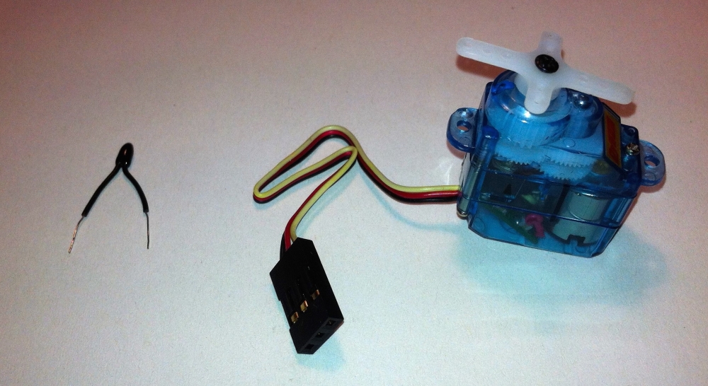
A thermistor and a small servomotor
The use of servomotors is very common in a multitude of projects but their management may be a bit tricky due to the fact that they need a specially forged train of pulses to operate.
The Arduino language comes here to our rescue once again by incorporating a library to deal with servomotors, which makes connecting and programming one of these devices a breeze.
A library is simply a set of functions already elaborated and tested to accomplish a task. In this example, we will use the servo Arduino library to deal with the one we are going to connect.
Here, you have the circuit we will use and its corresponding breadboard connections diagram.
As you see, we connect the thermistor just like the photocell or the potentiometer in our previous examples and this has been shown in the following image:
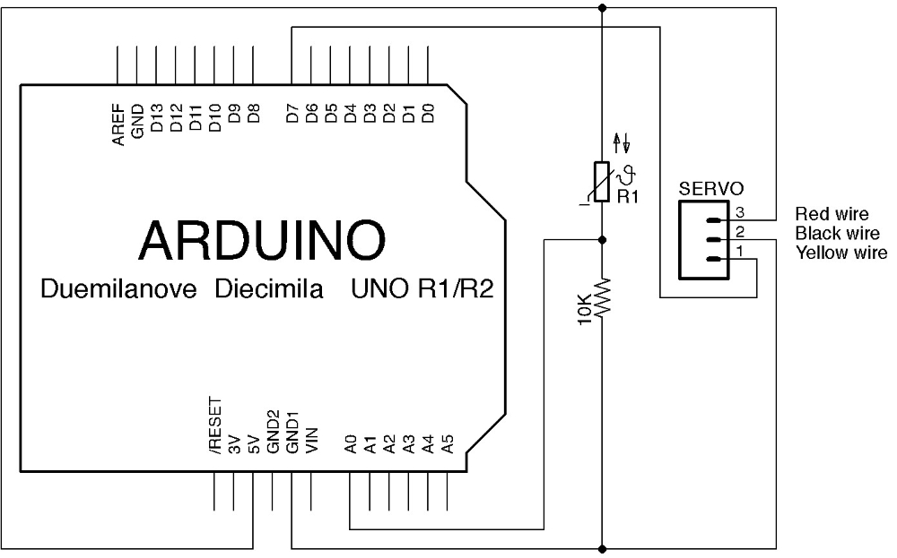
A thermometer with a dial circuit
The servomotor has three wires: V+, GND, and signal. We will connect the V+ wire (usually red) to 5V and the GND (black) wire to GND from the Arduino power pin header, and finally the signal one (usually yellow or white) to pin 7.
Perhaps you can see it better in the following breadboard connections diagram:
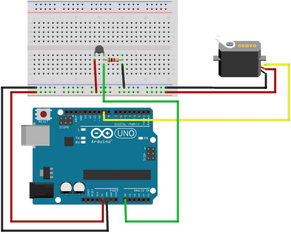
Breadboard connections diagram for the thermometer project
Here, you have the complete code for the dial thermometer project. It shouldn't be hard to understand:
/*
 Chapter 08 - Communicating with others
 Dial thermometer
 By Francis Perea for Packt Publishing
*/

#include <Servo.h>

// Global Definitions
// The pin used for the transistor base
#define servoPin 7
// The increment for the motor speed
#define thermistor 0

// Global variables we will use
// A variable to store the read temperature
int temperature;
// and another to store the servo angle
int angle = 0;
// A  servo object
Servo aServo;

// Configuration of the board: three outputs and one input
void setup() {
  // Set the thermistor pin as an output
  pinMode(thermistor,INPUT); // optional
  // Init serial communication
  Serial.begin(9600);
  aServo.attach(7);
}

// Sketch execution loop
void loop(){
  // We read the value of the thermistor
  temperature = analogRead(thermistor);
  // Map it to a valid angle
  angle = map(temperature, 750, 850, 0, 179);
  // Send both back to the serial monitor
  Serial.print(temperature);
  Serial.print(" : ");
  Serial.println(angle);

  // Position the servomotor accordingly
  aServo.write(angle);

  // Wait some time to avoid the servo to vibrate
  delay(100);
}
The only new thing in this code is the programming of the servomotor.
We begin by including the library with the following:
#include <Servo.h>
This allows us to declare a new instance of a servo object in the aServo variable with this:
Servo aServo;
In the setup() function, we call the aServo.attach(7) method of our new object to specify through which pin the servomotor will be commanded.
Finally in the main loop, we simply map the received value from the thermistor into a valid angle in the range 0–179 and use the obtained value to position the servomotor with a call to aServo.write(angle).
By sending the read value of the thermistor back to the computer via a serial communication, you can estimate the range of temperatures you want to control and allow the servo to represent. The proposed values 750–850 are the ones I found valid for my thermistor and the temperature ranges in my room, but I'm sure you will have to adapt to your specific configuration.
Here, you have an image of my particular assembly with a small gradient I printed to be used as the dial background:
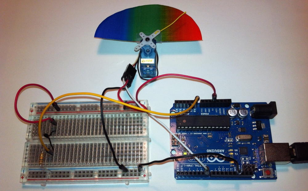
A thermistor and a small servomotor
A very simple project but also a very visual one that I'm sure will make a perfect introduction to the use of servos and the servo library.
If you want to know more about servos and the Arduino servo library, you could visit the servomotor entry at the Wikipedia site at http://en.wikipedia.org/wiki/Servomotor and the Arduino Reference page for the servo library at http://arduino.cc/en/Reference/Servo.