
In this chapter, I look at the Arduino-specific features of the C/C++ language which relate to the AVR microcontroller and how it operates, as opposed to looking at the C/C++ language in general.
![]() This chapter, and the following one, are long chapters, my apologies for that. I would advise that you do not try to get through them both in one sitting. Take a break every so often and go and do something with your Arduino – to take your mind off it! Sorry!
This chapter, and the following one, are long chapters, my apologies for that. I would advise that you do not try to get through them both in one sitting. Take a break every so often and go and do something with your Arduino – to take your mind off it! Sorry!
Digital I/O – meaning pinMode(), digitalRead(), and digitalWrite(). These functions can be found in the file $ARDINC/wiring_digital.c.
Analogue I/O – meaning analogReference(), analogRead(), and analogWrite(). These functions can be found in the file $ARDINC/wiring_analog.c.
Advanced I/O – meaning tone(), noTone(), pulseIn(), pulseInLong(), shiftIn(), and shiftOut(). These functions can be found in the file $ARDINC/wiring_shift.c.
Time – meaning delay(), delayMicroseconds(), micros(), and millis(). These functions can be found in the file $ARDINC/wiring.c.
Interrupt-related language features such as interrupts(), noInterrupts(), attachInterrupt(), and detachInterrupt() which can be found in the file $ARDINC/WInterrupts.c.
Various bit manipulation functions as found in the header files $ARDINC/Arduino.h and $ARDINC/wiring_private.h.
I will not be discussing the general C/C++ language functions, only those related to the Arduino Language. For the general ones, you should arm yourself with a good book on the subject.
Where possible, each function mentioned in the preceding text will be listed here in full, then dissected, and explained. If there are any foibles to be aware of, those will be discussed too. However, as the Arduino software for AVR microcontrollers covers many different types of AVR microcontrollers, I shall restrict the discussion of the software to that pertaining to the ATmega328P, and I will not be covering other microcontrollers – unless absolutely necessary.
Finally in the next chapter, I discuss the various C++ classes declared by the Arduino software that are included in almost every sketch. These are the Print, Printable, Stream, HardwareSerial, and String classes – although I don’t have much to say on the latter, apart from avoid!
Read on…
3.1 Digital Input/Output
This section takes a look at the functions which carry out digital input and output within the Arduino Language. These functions are pinMode() to set the pin’s mode and direction; digitalRead() to read the voltage state, HIGH or LOW, on a pin; and digitalWrite() to set the pin’s voltage, HIGH or LOW.
3.1.1 Function pinMode()
Example pinMode() usage
Input, where the pin state is determined by the voltage applied to it. The pin’s state would be read using digitalRead() and will result in a returned value of HIGH or LOW according to whatever voltage is currently being applied to the pin by external devices or components.
Input with the internal pullup resistor enabled, where the pin is used again for input, but the default state is pulled to HIGH when nothing else attached to the pin is attempting to pull it LOW. Using pullup resistors in this way can be done internally, as with the pinMode(switchPin, INPUT_PULLUP) example in Listing 3-1, or externally where there would be a resistor of about 10 K connected to the pin and to 5 V or 3.3 V depending on your Arduino board.
Output, where the pin state is set to HIGH or LOW by a call to digitalWrite(). Output pins, when set to HIGH or LOW by a call to digitalWrite(), will see the supply voltage 5 V or 3.3 V on the pin if set to HIGH or 0 V if set to LOW.
 A pin may be configured as an INPUT pin, but then written to, as if it was an OUTPUT pin, with digitalWrite() to set it HIGH. This will enable the internal pullup resistor which means that a digitalRead() on the pin will now see a HIGH unless the pin is being pulled to ground by some external influence.
This is exactly how the INTERNAL_PULLUP setting for pinMode() works.
When reading or writing a digital pin, the pin can take one of two different values. These are defined in $ARDINC/Arduino.h as HIGH and LOW, but what does this mean in relation to the voltage applied to, or seen on, the pin itself?
For Arduino boards running on a 5 V supply, a call to digitalRead() will return HIGH if the voltage on the appropriate pin is 3 V or higher. A LOW will be returned if the voltage on the pin is less than 1.5 V.
For Arduino boards running on a 3.3 V supply, a call to digitalRead() will return HIGH if the voltage on the appropriate pin is 2 V or higher. A LOW will be returned if the voltage on the pin is less than 1 V.
What about voltages in between? These are considered to be floating voltages, and the call to digitalRead() could return either a HIGH or a LOW depending on other circumstances and not necessarily the same result each time it is called for the same voltage. For this reason, it is best to avoid having input pins floating – so either use pullup resistors (internal or external) or, alternatively, pulldown resistors, which are external only.
![]() Floating pins are a really bad thing to have. A pin that is not electrically connected to supply or ground is a problem waiting to happen. How does your code see the value on the pin? It could be seen as HIGH sometimes, or LOW, and the code thinks that it is a valid reading – it is not. The value seen on the pin may be affected by many things – temperature, stray capacitance on the board, induced currents from external sources, or even you walking past. Never leave a pin floating.
Floating pins are a really bad thing to have. A pin that is not electrically connected to supply or ground is a problem waiting to happen. How does your code see the value on the pin? It could be seen as HIGH sometimes, or LOW, and the code thinks that it is a valid reading – it is not. The value seen on the pin may be affected by many things – temperature, stray capacitance on the board, induced currents from external sources, or even you walking past. Never leave a pin floating.
It may not be a major problem on a project designed to flash an LED from time to time, but for a high-powered laser cutter, for example, you really don’t want the laser turning on because the Arduino board thought a button had been pressed!
The file $ARDINC/Wiring_digital.c is where the source code for the digital functions pinMode(), digitalRead(), and digitalWrite() can be found. Additionally, there is one other function in this file, but it can only be called from the three functions listed. This helper function is turnOffPWM(), which is not discussed further, is declared static, and is there simply to turn off any PWM on a pin that is about to be used for digitalRead() or digitalWrite() purposes.
The pinMode() function takes two input parameters, a pin number and a mode, and sets the requested pin to the mode given. The modes are as discussed in the preceding text, while the pin number is just a number corresponding to the actual pin required.
You may not be aware, but the eight analogue pins A0–A7 on your Arduino board can also be used for digital I/O. They are numbered from D14, for pin A0, to D21 for pin A7. So a call to digitalWrite(14, HIGH) will set pin A0 to HIGH. This is useful when you need more digital pins than apparently supplied on the Arduino board.
Hang on! What do I mean A7? Surely I mean A5?
Some Arduino boards have been built with the surface mount versions of the ATmega328 device. These surface mount devices have a couple of extra pins connected to the ADC input, these being A6 and A7. Many clone boards have added two extra connectors to allow the boards to use these two additional pins, while some have not.
If you have an Arduino Nano, for example, then look carefully at the pin labels and you will see A6 and A7. These extra pins are not present on the 28-pin through-hole ATmega328P devices.
Sometimes you might see code referencing an additional ADC input pin, pin A8, which is an internal connection for the temperature sensor built in to the AVR microcontroller itself. You can read this input and get an idea of how hot the AVR microcontroller is running. Sadly, the Arduino Language does not make this visible using analogRead(). See the sketch in Appendix A for details on how to use this internal feature.
Getting back to pinMode(), we need to be aware first of all that the Arduino pin numbering system is completely different from that used by Atmel (now Microchip) who manufactures the AVR devices. What we call D1 is known to Atmel/Microchip as PD1, and the built-in LED on pin D13 is attached to the ATmega328P’s PB5 pin.
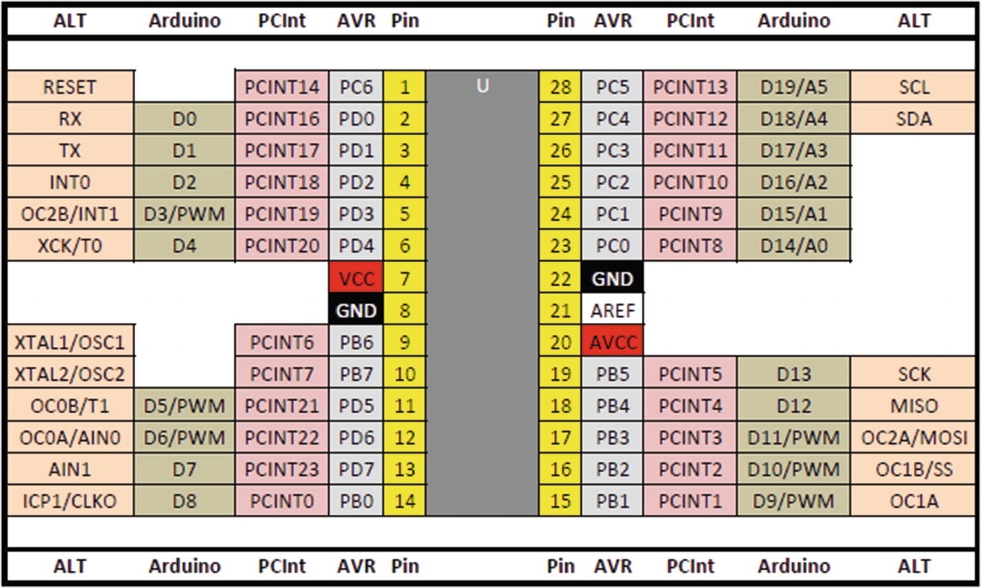
Pin names on the ATmega328P
The Arduino pin numbers are easily enough recognized as they are listed by name, in the two columns labeled Arduino, and there you will see names like D0 or A5 and so on. The Arduino Language has given these names to the various pins that are accessible using that language. However, Atmel/Microchip named the pins differently, and the Atmel/Microchip pin names can be seen in the AVR columns. Here you see names like PB2 or PD4 and so on. These are the actual pins that are used for digital input and output, or analogue input.
The bank’s Data Direction Register or DDR
The bank’s Pin Input Register or PIN
The bank’s Pin Output Register or PORT
DDRB, DDRC, and DDRD
PORTB, PORTC, and PORTD
PINB, PINC, and PIND
On the pinout image, when a pin is named PCn, where “n” is a number, then that particular pin belongs to bank C and uses DDRC, PORTC, and PINC.
The pinMode() function, among others, has to convert between the Arduino pin naming convention and the AVR’s own names. If, for example, pin D2 is being set to OUTPUT, the pinMode() function needs to convert D2 to DDRD, PORTD, and PIND2 so that manipulating that pin in Arduino code manipulates the PD2 pin on the ATmega328P.
Getting from D2, which is nothing more than the value 2, to a PORT, PIN, and DDR is done with the help of a few small data tables, set up in $ARDINST/variants/standard/pins_arduino.h.
The pinMode() function
① If we continue the preceding example with D2, then this pin has the value 2. This call to digitalPinToBitMask() converts D2 into an 8-bit value in which only bit 2 is set. This is therefore the value 4 as bit 2 in a byte indicates whether there are any 4s present in the value. The bitmask returned will look like 0000 0100binary with only bit 2 set.
② D2’s value, 2, is used again in a call to digitalPinToPort() which returns a value known as PD from the table digital_pin_to_port_PGM. PD is defined in Arduino.h to be the value 4. We now have the bitmask in bit and the port in reg. These are still not AVR microcontroller register names yet; they are still just numbers – both of them 4 in this example.
③ The port is validated; and if it is NOT_A_PIN, which has the value -1, we exit from the function.
④ The value for our port, 4, is then converted to a Data Direction Register and a PORT register using portModeRegister() and portOutputRegister(). These two functions read the tables port_to_mode_PGM and port_to_output_PGM and return pointers to the internal registers named DDRx and PORTx for the appropriate pin. In this example, these will be DDRD and PORTD. At this stage, pointers to the desired DDR and PORT registers are available in reg and out and can be manipulated to set a single pin to output mode.
⑤ If the requested mode is INPUT, we have to clear the appropriate bit in the DDR to configure an input pin, and as pullup has not been requested, the appropriate bit in the PORT register is also cleared to turn off the input pullup resistor for the pin. The current state of the status register is saved, and interrupts are turned off for the duration of the preceding changes. When the status register is restored, interrupts are reset to how they were before being disabled.
⑥ If the requested mode is INPUT_PULLUP, we have to clear the appropriate bit in the DDR to configure an input pin as in the preceding text, and as pullup has been requested, the appropriate bit in the PORT register is set to turn on the input pullup resistor for the pin. As earlier, the current state of the status register is saved, and interrupts are turned off for the duration of the preceding changes. When the status register is restored, interrupts are reset to how they were before being disabled.
⑦ If the requested mode is OUTPUT, we have to set the appropriate bit in the DDR to configure an output pin. There is no pullup on output pins. As before, when these changes are being made, the current state of the status register is saved and interrupts are turned off. When the status register is restored, interrupts are reset to their previous setting.
In the AVR microcontroller, writing a one to the DDRx register sets the pin to output, while writing a zero sets the pin to input. Input is the default when the AVR microcontroller is reset or powered on.
![]() Even though the default mode for a pin is INPUT in Arduino code, it is always beneficial to ensure that you explicitly set the pin in your code. It isn’t mandatory, but it can help make your code more readable and self-documenting.
Even though the default mode for a pin is INPUT in Arduino code, it is always beneficial to ensure that you explicitly set the pin in your code. It isn’t mandatory, but it can help make your code more readable and self-documenting.
As the example needs to set PORTD, bit 2, to output, then a one is required in the third bit of the bitmask – remember bits number from zero – and that is all. The code line *reg |= bit; does exactly that; it takes the bitmask 0000 0100binary and ORs it with whatever is currently in the register DDRD. This sets the pin to output, as required, and does not change the direction of any other pins on PORTD.
Had the mode requested been INPUT, then bit 2 in the DDRD register would need to be set to zero. The code *reg &= ~bit; does this by inverting the bitmask from 0000 0100binary to 1111 1011binary and then ANDing that with the current contents in the DDRD register. That would change only the third bit to a zero and would not affect any other pin. *out &= ~bit; then ensures that the pullup resistor is disabled for this pin.
If the mode is INPUT_PULLUP, then the *out |= bit; code makes sure that the pin is set to have its internal pullup resistor enabled by writing a 1binary to the PORTD register.
3.1.2 Function digitalRead()
Once a pin has been set for INPUT with pinMode(), then you can read the voltage on that pin with the digitalRead() function and change the behavior of your project according to the result obtained. The function will return either HIGH or LOW according to the voltage on the pin at the time of the function call.
The digitalRead() function
① This converts the pin’s number to a timer/counter number. This will be 0, 1, or 2. Timer/counters are used on pins that we can use analogWrite() upon. This is required as any pin which can be used for analogWrite() may be set to a value which is not a HIGH and not a LOW – a floating value in other words – and we need to avoid floating values.
② The pin’s number is converted to an 8-bit value where the only bit set will correspond to this pin’s position in the PINx register. Given the D2 example from earlier, this would be a bitmask of 0000 0100binary with only bit 2 set.
③ The pin is now also converted to the correct PINx register.
④ In order to read a digital value, LOW or HIGH, the pin should not be carrying out PWM. If the pin is one of the six that can be used with analogWrite(), then its ability to do so is temporarily disabled.
⑤ The correct PINx register is read and ANDed with the pin’s bitmask. If the result of the AND operation leaves the pin’s bit set in the PINx register, then HIGH is returned.
⑥ The pin must be at GND potential, so return a value of LOW.
![]() Timers, or, more correctly, timer/counters, are internal hardware features of the ATmega328P. These will be discussed in great detail in Chapter 8, along with many other useful features of the AVR microcontroller. What follows here is a brief discussion with only as much information as necessary to help understand the digitalRead() and digitalWrite() functions.
Timers, or, more correctly, timer/counters, are internal hardware features of the ATmega328P. These will be discussed in great detail in Chapter 8, along with many other useful features of the AVR microcontroller. What follows here is a brief discussion with only as much information as necessary to help understand the digitalRead() and digitalWrite() functions.
The timer/counters in the ATmega328P are named Timer/counter 0, Timer/counter 1, and Timer/counter 2. As described previously, Timer/counter 0 is used to ensure that the millis() count is incremented correctly (see Chapter 2, Section 2.9, “The init() Function,” for details). All three timer/counters are used to provide PWM facilities (analogWrite()) on two pins each. If there is a call to digitalWrite() for pins D3, D5–D6, or D9–D11, then the PWM must be turned off. This is done by finding out if the pin in question is connected to a timer/counter and, if so, calling turnOffPWM() for the particular timer.
The timer/counter in question is converted from a pin number by accessing the table digital_pin_to_timer_PGM which is defined in $ARDINST/variants/standard/pi s_arduino.h.
As with pinMode(), the port and bitmask are worked out from the two tables set up in $ARDINST/variants/standard/pins_arduino.h, and the port name (e.g., PD) is converted to an actual PINx register and the current value of that register is read. To continue the D2 example, this would be PIND, and the bitmask would be 0000 0100binary; bit 2 is set.
The PINx registers are connected to the physical pins on the AVR microcontroller, and reading those registers returns an 8-bit value where any external pin connected to a high enough voltage will be set to 1 and the others will be set to 0, if they are seeing a low enough voltage. Floating pins, always a bad idea, will return a fairly random value in the bit, which cannot be relied upon.
As digitalRead() is only interested in one single pin’s value, all the other bits are masked out by ANDing the returned value with the bitmask holding the correct pin. The function returns the result according to whether or not the bit in the PINx register was set to one or zero.
3.1.3 Function digitalWrite()
Once a pin has been set for OUTPUT with pinMode(), then you can set the voltage on that pin with the digitalWrite() function and change the behavior of your project by lighting up LEDs, activating relays and so on.
The digitalWrite() function
① The pin number is converted to a timer number, 0, 1, or 2. As with digitalRead(), this is required in case the pin is capable of being used with the analogWrite() function call.
② The pin number is also converted to an 8-bit value where the only bit set will correspond to this pin’s position in the PORTx register.
③ The pin number is converted to a port number.
④ If the port number is discovered to be invalid, digitalWrite() will quietly exit without changing the requested pin and without error. Your sketch will be none the wiser!
⑤ If the requested pin supports PWM, then the pin has PWM turned off.
⑥ The port number returned is converted to an actual PORTx register address and stored in a pointer variable, out.
⑦ The current value of the status register is saved to preserve the current state of global interrupts. Interrupts are then disabled globally. This will affect the status register and stops millis() from being accumulated.
⑧ If the value to be written to the pin is LOW, then the appropriate bit in the PORTx register is cleared to zero; otherwise, it is set to one. This turns the physical pin on the AVR microcontroller LOW or HIGH as appropriate.
⑨ The status register is restored which restores the previous state of the global interrupts.
As previously mentioned, all three timer/counters available in the ATmega328P are used to provide PWM facilities on two pins each. If there is a call to digitalWrite() for pins D3, D5–D6, or D9–D11, then the PWM on the requested pin must be turned off. This is done by finding out if the pin in question is connected to a timer/counter and, if so, calling turnOffPWM() for the particular timer/counter.
As with digitalRead(), the port and bitmask are worked out from the two tables set up in $ARDINST/variants/standard/pins_arduino.h, and the port name (e.g., PD) is converted to an actual PORTx register. To continue the D2 example, this would be PORTD, and the bitmask would be 0000 0100binary in binary; bit 2 is set.
The PORTx registers are, like the PINx registers, connected to the physical pins on the AVR microcontroller; and writing to those registers will cause the voltage on the physical pin to change to supply or ground potential, depending on whether the bit in the PORTx register is a one or a zero.
As digitalWrite() is only interested in setting a single pin’s value, all the other bits are masked out by ANDing or ORing the bitmask holding the correct pin with the current contents of the PORTD register. This affects only the bit that is set in the bitmask, and none of the other pins change. AND is used to clear the bit, while OR is used to set it.
3.2 Analogue Input/Output
This section takes a look at the functions which carry out analogue input and output within the Arduino Language. These functions are analogReference() to set the reference voltage for the analogue circuitry in the ATmega328P , analogRead() to read a voltage between 0 V and the reference voltage on a pin, and analogWrite() to set a pin’s voltage to somewhere between 0 V and the reference voltage.
3.2.1 Function analogReference()
The default, which is to use the supply voltage of 5 V or 3.3 V depending on the device. The ATmega328P on Arduino boards uses a 5 V supply.
An internally generated 1.1 V reference voltage. This must be used if the internal temperature sensor is being used as the ADC input. See Appendix E for a small sketch showing how this can be done.
An external reference voltage on the AREF pin. This must be between 0 V and 5 V, or damage to the AVR microcontroller will occur.
 The data sheet for the ATmega328P warns that If the user has a fixed voltage source connected to the AREF pin, the user may not use the other reference voltage options in the application, as they will be shorted to the external voltage. If no external voltage is applied to the AREF pin, the user may switch between AVCC and 1.1V as reference selection.
The preceding warning must be noted. On my own Arduino boards, AREF isn’t connected at all (according to the schematics), and the temperature measuring sketch mentioned earlier works fine. There is a location on one of the headers labeled “AREF” where the maker can supply a voltage to the AREF pin. I have never connected anything to that pin, so I’m safe.
![]() There are many, many places on YouTube, on the Internet in general, and in some books where there are circuit diagrams, usually created in Fritzing, which show how you can remove all the extraneous gubbins from an Arduino board and create your own pseudo-Arduino on a breadboard. These usually show that there are three connections to the 5 V supply – VCC, AVCC, and AREF.
There are many, many places on YouTube, on the Internet in general, and in some books where there are circuit diagrams, usually created in Fritzing, which show how you can remove all the extraneous gubbins from an Arduino board and create your own pseudo-Arduino on a breadboard. These usually show that there are three connections to the 5 V supply – VCC, AVCC, and AREF.
This connection of AREF to VCC is completely wrong as it prevents you from being able to select the internal 1.1 V reference for the ADC or the Analogue Comparator and will have the result, if you upload a program that does select the internal reference voltage, of potentially bricking your AVR microcontroller. Not a good idea.
My advice is to treat those circuits with disdain and never connect AREF to any supply voltage, unless you absolutely need to do so, as this will help your AVR microcontroller live long and prosper. (This, I think, is a phrase taken from some 1960s space exploration series on TV!)
The analogReference() function
DEFAULT which has value 1.
INTERNAL which has value 3.
EXTERNAL which has value 0.
All of these are defined as constants in the $ARDINC/Arduino.h header file. You may be wondering about why those exact values have been used. The description of analogRead() will tell all!
3.2.2 Function analogRead()
The analogRead() function connects the pins A0–A5, or A0–A7 if your board has the surface mount version of the ATmega328 and the manufacturer chose to connect A6 and A7 to header pins, to the multiplexed inputs of the AVR microcontroller’s Analogue to Digital Converter (ADC).
The ADC can read a voltage on those pins; and using a method called successive approximation, it can work out, with reasonable accuracy, what the voltage was. Wikipedia has a good explanation of how successive approximation works at https://en.wikipedia.org/wiki/Successive_approximation_ADC if you are interested further.
If you think back to the previous section on the analogReference() function, you may remember I asked why the constants defined for DEFAULT, INTERNAL, and EXTERNAL had the values 0, 3, or 1? The simple reason is because when they are shifted left by six places, they take up position in the REFS1 and REFS0 bits of the ADMUX register and are ready to go without any further processing being required. Sneaky! (And efficient.)
![]() The register names may not be very meaningful to you at this stage; however, in Chapters 7, 8, and 9 where I look at the hardware features of the ATmega328P, which the code here depends upon, all will, hopefully, become clear. You may, if you wish, skip to Chapter 9 and read all about the ADC or just take my word for it until then!
The register names may not be very meaningful to you at this stage; however, in Chapters 7, 8, and 9 where I look at the hardware features of the ATmega328P, which the code here depends upon, all will, hopefully, become clear. You may, if you wish, skip to Chapter 9 and read all about the ADC or just take my word for it until then!
Basically, there are two bits in the control registers for the ADC which tell it where to obtain the reference voltage it needs to convert from an analogue voltage to a digital value representing the voltage. Those two bits are named REFS1 and REFS0. By shifting the DEFAULT, EXTERNAL, or INTERNAL values into those bits, the correct reference voltage is selected.
AnalogReference values and sources
Name | Value | Binary | REFS1 | REFS0 | Reference Used |
|---|---|---|---|---|---|
DEFAULT | 0 | 00 | 0 | 0 | Default reference is the supply voltage, 5 V or 3.3 V depending on the device. |
EXTERNAL | 1 | 01 | 0 | 1 | Default reference is the voltage supplied on the AVCC pin, 5 V or 3.3 V depending on the device. |
INTERNAL | 3 | 11 | 1 | 1 | Default reference is the internally generated 1.1 V voltage. |
![]() The data sheet notes that the value 2 or 10binary is reserved and should not be used.
The data sheet notes that the value 2 or 10binary is reserved and should not be used.
It should be noted that the data sheet for the ATmega328P states that if INTERNAL or EXTERNAL references are being used, there should be a small capacitor between the AREF pin and ground. The Duemilanove and Uno boards use a 100 nF capacitor according to the schematics.
The analogRead() function
① Here, the pin number passed in is adjusted to ensure that it is between 0 and 7. In case anyone passed D14, or 14, for A0, which is perfectly valid, this adjustment ensures D14 becomes A0 which has the numeric value of zero.
② Whatever the user sets as the desired value for analog_reference is copied up into the appropriate bits of the ADMUX register, alongside the correct three bits for the desired analogue pin.
③ This comment is obviously incorrect in this version of the Arduino IDE, as the desired delay(1) is itself commented out!
④ Ask the ADC to initiate a conversion of the voltage on the requested pin to a digital value. ADSC is the “ADC Start Conversion” bit.
⑤ Hang around here, burning CPU cycles, while the ADC does its conversion. When it is complete and a result is available, bit ADSC in the ADCSRA register will be cleared. The result of the ADC’s conversion will be available in the ADCL and ADCH registers.
⑥ As per the comment, and the data sheet, we must read the low value first and then the high value; otherwise, we would potentially get an incorrect reading. Reading ADCL locks the result until ADCH is read; it is then unlocked again. The ADC can be configured in other modes which make repeated readings – you would not want to have read the ADCL and get a different reading’s value in ADCH!
⑦ The highest 2 bits of the value are in high, while the lower 8 bits are in low – here we combine these into a 16-bit value to return as the result.
![]() The source code shown in the preceding text is not exactly as it appears in $ARDINC/wiring_analog.c. I have stripped out a lot of checks, function calls, and assignments which are not relevant to the ATmega328P. Hopefully, this makes things a lot easier to understand. It certainly saves space on the page!
The source code shown in the preceding text is not exactly as it appears in $ARDINC/wiring_analog.c. I have stripped out a lot of checks, function calls, and assignments which are not relevant to the ATmega328P. Hopefully, this makes things a lot easier to understand. It certainly saves space on the page!
3.2.3 Function analogWrite()
The code for the analogWrite() function is found in the file $ARDINC/wiring_analog.c.
The analogWrite() function is used to write an 8-bit data value to one of the six pins that support pulse width modulation (PWM) which allows the voltage read on the pin to appear as a value between GND and VCC. Chapter 8 explains the various timer/counter features, including the various forms of PWM that are available, how PWM works, and how a supposedly digital device is able to make analogue voltages appear on its pins.
The analogWrite() function takes a value between 0 and 255 and uses it to define the duty cycle (see Chapter 8, Section 8.1.7.1, “Duty Cycle ”) of the PWM timer/counter connected to the appropriate pin. The higher this value is, the longer the duty cycle of the PWM signal on the pin will be and, therefore, the higher the apparent voltage on the pin will appear to be.
The analogWrite() function will always set the appropriate pin to be in OUTPUT mode, and if the pin requested is not one that allows PWM, then a digitalWrite() takes place on the pin, with values less than 128 indicating that the pin should be set to LOW and higher values setting the pin to HIGH.
As you will see from Listing 3-7, all that the analogWrite() function does is decide which timer/counter and channel that the requested pin number should be connected to, connects it to that timer/counter and channel, and sets the duty cycle. Each timer/counter has two separate channels available for PWM output, and as there are three timer/counters on the ATmega328P, we have PWM on six pins.
PWM pins, timers, and channels
PWM Pin | Timer Used | Timer Channel |
|---|---|---|
D3 | Timer 2 | Channel B |
D5 | Timer 0 | Channel B |
D6 | Timer 0 | Channel A |
D9 | Timer 1 | Channel A |
D10 | Timer 1 | Channel B |
D11 | Timer 2 | Channel A |
The various timer/counters are separate parts of the ATmega328P and operate separately from the brain of the microcontroller – the CPU. This allows the timer/counters to be set and left to get on with timing or counting while the CPU continues running the program.
![]() The two channels of each timer/counter operate independently of each other. This allows pin D5 to have one value written by analogWrite() and pin D10 to have another, different value. This applies because of the PWM mode chosen by the designers of the Arduino Language and system and is explained in some detail in Chapter 8 which deals with the timer/counter hardware in the ATmega328P.
The two channels of each timer/counter operate independently of each other. This allows pin D5 to have one value written by analogWrite() and pin D10 to have another, different value. This applies because of the PWM mode chosen by the designers of the Arduino Language and system and is explained in some detail in Chapter 8 which deals with the timer/counter hardware in the ATmega328P.
The analogWrite() function
① The pin is made an output pin, and as a quick test and return, if the value is either 0 or 255, the two limits for analogWrite(), then the pin is simply set to ground or supply voltage using digitalWrite(). This avoids a slight timing error when the timer/counter is in PWM mode and is set to one of its limits. The data sheet has details, if you wish to investigate further.
② The pin is converted to a timer/counter and channel by way of a call to digitalPinToTimer() which uses the table digital_pin_to_timer_PGM created in $ARDINST/variants/standard/pins_arduino.h to determine if the pin is a PWM pin or otherwise. This returns a value of NOT_ON_TIMER if the pin is purely digital, and that will be handled by the default case.
③ This is where pin D6 is configured. The pin is connected to the timer/counter, and the OCR0A register is loaded with the value passed to analogWrite() to enable the correct duty cycle for the timer/counter’s PWM output. D6 is on Timer/counter 0, channel A.
④ Configuration of pin D5 is performed here and sets up D5 on Timer/counter 0, channel B.
⑤ This is where pin D9 is configured to use Timer/counter 1, channel A.
⑥ Pin D10 configuration happens here. Pin D10 uses Timer/counter 1, channel B.
⑦ Pin D11 is configured here and uses channel A on Timer/counter 2.
⑧ Pin D3 is configured here. D3 is configured to use channel B on Timer/counter 2.
⑨ In the event that the supplied pin number is not able to output PWM, this part of the code digitally sets the pin LOW or HIGH according to the requested PWM value passed to analogWrite().
The Arduino Reference web site at www.arduino.cc/reference/en/language/functions/analog-io/analogwrite/ warns that
The PWM outputs generated on pins 5 and 6 will have higher-than-expected duty cycles. This is because of interactions with the millis() and delay() functions, which share the same internal timer used to generate those PWM outputs. This will be noticed mostly on low duty-cycle settings (e.g. 0–10) and may result in a value of 0 not fully turning off the output on pins 5 and 6.
Looking at the code in Listing 3-7, a value of zero will ignore PWM altogether and simply use digitalWrite() to turn off the pin. I suspect the warning may refer to older types of Arduino boards. The ATmega328P data sheet also advises against PWM values of zero or TOP where TOP is the configured highest value for the timer/counter in use. I would say that the checks in Listing 3-7 which test for 0 or 255 are obviously there to get around the problem.
![]() A pin can be HIGH or LOW. PWM turns a pin HIGH and LOW, and the sum of one HIGH plus one LOW is the period. This is related to the PWM frequency which is defined by the timer/counter’s prescaler – Chapter 8, Section 8.1.7.2, “PWM Frequencies”, has all the gory details.
A pin can be HIGH or LOW. PWM turns a pin HIGH and LOW, and the sum of one HIGH plus one LOW is the period. This is related to the PWM frequency which is defined by the timer/counter’s prescaler – Chapter 8, Section 8.1.7.2, “PWM Frequencies”, has all the gory details.
Duty cycle is usually expressed as a percentage. It defines the time that the pin is HIGH as a percentage of the period. A duty cycle of 10% means that the pin is HIGH for 10% of its period and LOW for the remaining 90%. A 10% duty cycle would appear as a voltage very close to 10% of VCC on the PWM pin.
3.3 Advanced Input/Output
In this section, I take you through the advanced input/output functions which allow you to make sounds and measure logic levels on pins to determine how long a specific state was held for and an easy way to shift a byte value from a variable out onto a digital pin and vice versa.
3.3.1 Function tone()
The code for the tone() function is found in the file $ARDINC/Tone.cpp.
The tone() function generates a square wave of the specified frequency, with a 50% duty cycle, on any pin. A duration can be specified; otherwise, the wave continues until a call to noTone(). The pin can be connected to a piezo buzzer or another speaker to play tones.
If tone() has been called, then PWM on pins D3 and D11 will be affected. These analogue pins are maintained by Timer/counter 2, and it is Timer/counter 2 that the tone() function uses to generate a square wave.
If you have, for example, a pair of LEDs, fading in and out, on pins D3 and D11, then whenever the tone() function is called, and while sounding a tone, the LEDs will be off. Fading LEDs, on the other pins available for analogWrite(), will not be affected. Those are pins D5, D6, D9, and D10. Only pins D3 and D11 are affected by this problem.
Brett Hagman’s GitHub site, https://github.com/bhagman/Tone#ugly-details, which is linked to the Arduino Reference web site, www.arduino.cc/reference/en/language/functions/advanced-io/tone/, has the following to say, as a warning:
![]() Do not connect the pin directly to some sort of audio input. The voltage on the output pin will be 5 V or 3.3 V and is considerably higher than a standard line-level voltage (usually around 1 V peak to peak) and can damage sound card inputs and others. You could use a voltage divider to bring the voltage down, but you have been warned.
Do not connect the pin directly to some sort of audio input. The voltage on the output pin will be 5 V or 3.3 V and is considerably higher than a standard line-level voltage (usually around 1 V peak to peak) and can damage sound card inputs and others. You could use a voltage divider to bring the voltage down, but you have been warned.
You must have a resistor in line with the speaker, or you will damage your microcontroller.
The resistor mentioned is shown on Brett’s circuit diagram as having a value of 1 K. That should, if I can do the calculations properly, restrict the current to 5 milliAmps.
![]() Brett is the author of the Tone Library, a simplified version of which has been included with the Arduino IDE, since version 0018.
Brett is the author of the Tone Library, a simplified version of which has been included with the Arduino IDE, since version 0018.
Example tone() function calls
The duration, if it is omitted or zero, causes the tone to sound forever or until noTone() is called.
On the Arduino boards based around the ATmega328P, only one pin can be generating a tone at any time. If a tone is already playing on a pin, a call to tone() with a different pin number will have no effect unless noTone() was called first. If the call is made for the same pin as the one currently playing, the call will set the tone’s frequency to that specified in the most recent call.
In order for tone() to function correctly, a couple of tables are required to be set up to control which timer/counter will be used to generate a tone and to keep a record of all the pins that are currently generating. This code is shown in Listing 3-9.
Variables used by the tone() function
① This shows that the ATmega328 family has only one pin that can play at any one time – at least on the version of the code included with the Arduino IDE version 1.8.5.
② This tells the code, later on, which interrupt routine to use, to do the actual tone generation.
③ This array, which is created in the AVR microcontroller’s flash memory, holds a list of the various timer/counters that can be used to generate tones. As the tone() function is a cut-down version of Brett’s library, only a single timer/counter is used; currently, this is Timer/counter 2.
④ This array, which is created in the AVR microcontroller’s Static RAM, holds a list of all the pin numbers that are currently playing a tone, or 255 if nothing is playing. There is one entry in the table for each timer/counter that can be used to generate tones. That means there is one entry in total for the ATmega328P boards. There can be only one (www.imdb.com/title/tt0091203/ – well, I am a Highlander!).
As you can see from the preceding text, the ATmega328P-based boards only have a single timer/counter in use to generate tones, this being Timer/counter 2.
Variables used by the tone() function ISR
![]() You will note that all of these are declared volatile. This is because they will be used in an interrupt service routine (ISR), and any variable you wish to read or write during an interrupt must be declared as being volatile. If you forget, your code may not work because the compiler optimized the variable away.
You will note that all of these are declared volatile. This is because they will be used in an interrupt service routine (ISR), and any variable you wish to read or write during an interrupt must be declared as being volatile. If you forget, your code may not work because the compiler optimized the variable away.
The variable timer2_toggle_count holds the number of times that the interrupt routine will be called, if a duration for the tone is requested. If no duration is requested, this is unused.
Timer2_pin_port is related to the internal register to be used for the PORTx port for the pin which will be generating the sound, while timer2_pin_mask is a bitmask with a single bit, corresponding to the required pin, set to one. This indicates which bit in the PORTx register is being used to generate the sound.
The tone() function works by working out a suitable prescaler for the timer/counter clock so that the number of ticks to be counted per transition (LOW to HIGH or HIGH to LOW) of the pin falls into the range 0–255. This is required because Timer/counter 2 is only 8 bits wide and can only count within this range.
If the frequency chosen is such that even with a prescaler of 1024 in use the value still cannot fall in the range required, the code simply attempts to carry on regardless. This may render the tone generated to be the wrong frequency.
The tone() function
① The call to toneBegin() returns a timer/counter number. On the standard Arduino boards, based around the ATmega328 family of AVR microcontrollers, this will be Timer/counter 2. The toneBegin() function is discussed in Listing 3-13.
② These lines onward attempt to fit the required frequency into the range 0–255 using any of the available Timer/counter 2 prescaler values.
The frequency of the system clock, 16 MHz, is divided by twice the required frequency – because in order to make a tone, the pin must be raised and lowered – LOW ➤ HIGH ➤ LOW. This is then divided by the prescaler value being considered. The subtraction of one from the result is because the AVR microcontroller counts from zero.
If the result fits into an 8-bit value, then the current prescaler value will be used.
③ This is the last resort at fitting the frequency into range. If the prescaler set to divide by 1024 still cannot fit, then the code simply carries on regardless. This could result in the frequency being a tad wrong.
④ After the call to toneBegin() – see in the following – Timer/counter 2 is set up to run with no prescaling, so the calculated prescaler bits must be set up in the TCCR2B register, in bits CS22–CS20. See Chapter 8 for a full description of prescalers.
These bits will be set to whatever is in the lowest 3 bits of the prescalarbits variable. This sets the timer/counter to the correct prescaler value for the frequency that is required to be generated.
With a prescaler of 1, the value calculated is 18,180 which cannot be used in an 8-bit timer/counter.
With a prescaler of 8, the value calculated is 2,271 which cannot be used in an 8-bit timer/counter.
With a prescaler of 32, the value calculated is 567 which cannot be used in an 8-bit timer/counter.
With a prescaler of 64, the value calculated is 283 which cannot be used in an 8-bit timer/counter.
With a prescaler of 128, the value calculated is 141 which can be used in an 8-bit timer/counter.
With a prescaler of 256, the value calculated is 70 which could be used but won’t be as prescaler 128 was found to fit.
With a prescaler of 1024, the value calculated is 16 which could be used but won’t be as prescaler 128 was found to fit.
Of these, the first one to fit into the range 0–255 is a prescaler of 128. So the ocr variable is set to 141, and the prescalarbits variable is set to 101binary to select a divide-by-128 prescaler.
The tone() function, continued
① The duration is checked, and if it is specified, then the tone must only be generated for that length of time. The duration supplied to tone() is specified in milliseconds; however, as frequency is measured in cycles per second, the value is converted to seconds.
Continuing the preceding example of a 440 Hz tone, if the duration is required to be 1.5 seconds, then the toggle_count variable is set to 2 * 440 * 1.5 or 1320. This is the number of times in 1.5 seconds that the pin must be toggled, to ensure that a 440 Hz tone is generated.
② The ocr value is the maximum count that the timer/counter counts up to before it clears to zero and causes an interrupt. Unlike the millis() interrupt routine, which counts from 0 to 255 (on Timer/counter 0), the maximum value for this timer/counter, when generating tones, is based on the frequency and the calculated prescaler value.
Once more, with the current example, the timer/counter will count from 0 to 141 and toggle the pin, then again from 0 to 141 and again toggle the pin, and so on, for the desired duration.
③ If a duration was specified, the number of times the pin must be toggled is written to the timer2_toggle_count variable which will be used to disable the tone, in the interrupt routine, when the duration has passed. This is -1 if no duration was requested.
④ The setting of the bit OCIE2A in register TIMSK2 enables the Timer/counter 2 Compare Match A interrupt. That interrupt routine is the code that actually toggles the pin to cause the sound to be generated and is discussed in Listing 3-14.
The toneBegin() function
① The toneBegin() code starts by checking the tone_pin_to_timer_PGM array to see if the requested pin is currently generating a tone. If it is, the code simply returns the timer/counter number to tone() – on an ATmega328P-based Arduino board, this is always Timer/counter 2.
② The tone_pins array is searched for an unused pin. If an entry is found, the tone_pin_to_timer_PGM array is read to determine the timer/counter number that can be used. There’s only one timer/counter on Arduino boards, Timer/counter 2.
③ If there were no free slot(s) in the tone_pins array, toneBegin() exits, returning -1 to the calling code in tone().
- ④ Much bit twiddling then ensues to initialize Timer/counter 2 with
Bit WGM21 set in register TCCR2A to put the timer/counter into “Clear Timer on Compare” mode. The counter value will reset to zero whenever it reaches the value in OCR2A.
Bit CS20 set in register TCCR2B to put the timer/counter into “no prescaling” mode – the timer/counter’s clock will run at the system clock speed, 16 MHz. This will be amended on return to tone() when the frequency-dependent prescaler value is calculated.
The variable timer_pin_port is determined next. This is based on the pin requested and will be PORTB, PORTC, or PORTD on the ATmega328P.
The required pin’s bitmask, in timer2_pin_mask, is calculated next. This will be an 8-bit value, with a single bit set to indicate the required pin, on the just calculated PORTx register.
The ISR for the tone() function
① If there are still toggles to be done, then the pin must be toggled.
② The appropriate PORTx register has its bits XORd with the pin’s bitmask. This toggles just the bit that is set to indicate which pin is being used to generate a tone. If the bit is currently a one, then XORing with the 1 bit in the mask will set the PORTx register’s bit to a zero and vice versa. This sets the physical pin HIGH or LOW accordingly.
③ The number of toggles remaining for the required duration is reduced.
④ If there were no more toggles to be done, then a call is made to the noTone() function to silence the sound.
The old code following this line has been commented out. This is now because noTone() disables the timer/counter and sets the pin to LOW.
The Arduino Reference web site, www.arduino.cc/reference/en/language/functions/advanced-io/tone/, has the following to say about tone():
If you want to play different pitches on multiple pins, you need to call noTone() on one pin before calling tone() on the next pin.
It is not possible to generate tones lower than 31Hz. For technical details, see Brett Hagman’s notes. (https://github.com/bhagman/Tone#ugly-details)
Use of the tone() function will interfere with PWM output on pins 3 and 11 (on boards other than the Mega).
3.3.2 Function noTone()
The code for the noTone() function is found in the file $ARDINC/Tone.cpp.
The noTone() function
① If the pin number supplied is currently generating a tone, then it is converted to a timer/counter number. In ATmega328P variants of the Arduino board, this will always be Timer/counter 2 – that’s the only timer/counter currently used for tone generation.
② This indicates that no pins are generating a tone.
③ If the pin was not generating a tone, the _timer variable will be set to -1, and that will have no effect in disableTimer(). Otherwise, Timer/counter 2 will be disabled, stopping the generation.
④ The pin is set LOW, regardless of whether it was generating a tone or not. This contradicts the documentation for noTone() at www.arduino.cc/reference/en/language/functions/advanced-io/notone/ where it states that this has no effect if no tone is being generated on the specified pin when called. This is definitely not the case if the pin was actually HIGH when noTone() was called on it.
The disableTimer() function
① Setting bit OCIE2A in register PIMSK2 turns off the “Timer/counter 2 Compare Match A” interrupt which had been turned on by the toneBegin() function, itself called from the tone() function.
② This resets Timer/counter 2 into “Phase Correct PWM” mode originally set up in init() but which was changed to “Clear Timer on Compare” mode by the toneBegin() function, called from tone().
③ This resets the prescaler back to divide by 64 for Timer/counter 2. The tone() function changed that setting according to the frequency of the tone that was requested.
④ This resets the “Output Compare A” value for the timer/counter.
The effect of the preceding code is to restore the state of Timer/counter 2, its interrupts and so on, back to those configured in the initial setup within the init() function as described in Chapter 2, Section 2.9, “The init() Function.”
The Arduino Reference web site at www.arduino.cc/reference/en/language/functions/advanced-io/notone/ has the following to say on noTone():
If you want to play different pitches on multiple pins, you need to call noTone() on one pin before calling tone() on the next pin.
3.3.3 Function pulseIn()
The pulseIn() function , found in the file $ARDINC/wiring_pulse.c, is used to measure the period of a pulse on any pin. There is an alternative function, pulseInLong(), which is discussed later, which is better at handling long-duration pulses than pulseIn(); however, pulseIn() can be used in sketches where interrupts are disabled.
Calling the pulseIn() function
The return value is an unsigned long.
If no timeout is specified, the default is one second. The timeout is specified in microseconds – millionths of a second.
Wait for the pin in question to become HIGH if it currently is LOW. If the timeout expires before the pin goes HIGH, the function returns zero. Thus, the code is waiting for the current pulse to end.
Wait for the pin to go LOW again – this is the start of the pulse to be measured. Once more, if the remaining time left in the timeout expires, the function returns zero.
Wait for the pin to go HIGH again – this is the end of the pulse to be measured. If the remaining time left in the timeout expires, then the function again returns zero; otherwise, it returns the time, in microseconds, that the pin remained LOW.
 To be absolutely clear, the timeout you pass to the function is used for all of the function – waiting for the current pulse to finish, waiting for the new pulse to start, and then waiting for the new pulse to complete – one timeout to rule them all.
Similar, but opposite, actions take place when pulseIn() is called with a state of HIGH.
Unlike the function pulseInLong(), pulseIn() can be executed when interrupts are disabled as it does not require the micros() function.
C code version of countPulseASM()
① The pulse length will be returned in the width variable; here, it is initialized to zero.
② The function returns zero if the timeout expired while waiting for the current pulse to end.
③ The function returns zero if the timeout remaining expired while waiting for the new pulse to begin.
④ The function returns zero if the timeout remaining expired while the new pulse was being measured.
⑤ The pulse has been successfully measured, and the variable width holds its width as the number of while loops which were executed while measuring the pulse length.
The pulseIn() function
① The supplied pin number is converted to a bitmask. As with all calls to digitalPinToBitMask(), the bitmask returned is an 8-bit binary value, with a single bit set to one. This bit represents the desired physical pin on the AVR microcontroller and its appropriate position in the PORTx and PINx registers.
② The appropriate port (PB, PC, or PD) is obtained from the pin number.
③ The stateMask variable is set to zero for LOW or to the pin’s bitmask for HIGH.
④ The timeout counter is initialized to the required number of microseconds multiplied by 16 as the assembly code will loop in system clock cycles as opposed to microseconds.
- ⑤ The assembly language code is called to
Wait for the current pulse on the pin to end or the timeout to expire.
Wait for the pin to begin a new pulse or the timeout to expire.
Wait for the pulse to end or the timeout to expire.
The call to portInputRegister() will convert the pin’s port number, PB, PC, or PD, to the appropriate PINx register in the AVR microcontroller; and this will be passed to the assembly code.
⑥ The width value is converted from the number of while loops executed while measuring the pulse to microseconds. Each loop takes 16 microseconds, so width is multiplied by 16. It now holds the number of clock cycles it spent in the loop. An additional 16 is added for the overhead of calling and returning from the countPulseASM() function. These clock cycles are then converted to microseconds by the clockCyclesToMicroseconds() function.
 The reason that the code calls out to an assembly language routine is at first a little mysterious, especially as the assembly code was, it appears, created from C code originally. Why not just call the C code again?
Well, what happens to the timings in the C code if, somehow, a compiler version that is later used by the IDE implements a new optimization that makes the generated code run much more quickly? The timings will be off somewhat.
Running a standard assembly language routine, where the actual timings of each and every instruction are known, means that no matter what improvements are made in the compiler, the existing countPulseASM() function will continue to run at exactly the same speed, thus keeping the results of pulseIn() consistent.
The Arduino Reference web site (www.arduino.cc/reference/en/language/functions/advanced-io/pulsein/) gives the following notes about the pulseIn() function:
The timing of this function has been determined empirically and will probably show errors in longer pulses. Works on pulses from 10 microseconds to 3 minutes in length.
Example usage of pulseIn()
However, the example code doesn’t do anything with the returned result!
3.3.4 Function pulseInLong()
The pulseInLong() function is found in the file $ARDINC/wiring_pulse.c. It is an alternative to the pulseIn() function previously described and is better at handling long-duration pulses. It cannot, however, be used in sketches where interrupts are disabled.
Calling the pulseInLong() function
The return value is an unsigned long.
If no timeout is specified, the default is one second. The timeout should be specified in microseconds – millionths of a second.
Wait for the pin in question to become LOW if it currently is HIGH. If the timeout expires before the pin goes LOW, the function returns zero. Thus, the code is waiting for the current pulse to end.
Wait for the pin to go HIGH again – this is the start of the pulse to be measured. Once more, if the remaining time left in the timeout expires, the function returns zero.
Wait for the pin to go LOW again – this is the end of the pulse to be measured. If the remaining time left in the timeout expires, then the function again returns zero; otherwise, it returns the time, in microseconds, that the pin remained HIGH.
Similar, but opposite, actions take place when called with a state of LOW.
The pulseInLong() function
① Your attention is drawn to this comment. Because the code uses the micros() function, it cannot be used if the global interrupts have been turned off, as the call to micros() will not change without interrupts, specifically, the Timer/counter 0 Overflow interrupt. The micros() function is discussed in Section 3.4.3, “The micros() Function.”
② The supplied pin number is converted to a bitmask.
③ The appropriate port (PB, PC, or PD) is obtained from the pin number.
④ The timeout counter is initialized. Because this uses micros(), interrupts must be enabled, and the default interrupt handler for the Timer/counter 0 Overflow interrupt must be configured. (This is done at startup in the init() function as discussed in Chapter 2.)
⑤ The wait for the pin to stop being in the state we are considering happens here. If the timeout expires during the wait, the function returns zero. The pulse did not occur.
The call to portInputRegister() will convert the pin’s port number, PB, PC, or PD, to the appropriate PINx register in the AVR microcontroller.
⑥ The wait for the pin to start the next pulse happens here. If the remaining timeout expires during the wait, the function returns zero. The pulse did not occur.
⑦ A new pulse has started, so the time that it started is recorded in start.
⑧ The function waits while the pulse continues. If the timeout expires while waiting, the function will once again return zero to indicate that the pulse did not get measured completely within the timeout period.
⑨ If the pulse did complete before the timeout expired, the function returns the time that the pin was in the state that the sketch was interested in.
The description of pulseinLong() at www.arduino.cc/reference/en/language/functions/advanced-io/pulseinlong/ gives the following notes about the function:
The timing of this function has been determined empirically and will probably show errors in shorter pulses. Works on pulses from 10 microseconds to 3 minutes in length. This routine can be used only if interrupts are activated. Furthermore the highest resolution is obtained with large intervals.
This function relies on micros() so cannot be used in the noInterrupts() context.
Example usage of pulseInLong()
However, the example doesn’t do anything with the returned result!
3.3.5 Function shiftIn()
The code for the shiftIn() function is found in the file $ARDINC/wiring_shift.c.
The shiftIn() function is used to read an 8-bit data value, 1 bit at a time, from an external device, for example, a shift register.
The operation may be carried out with the most significant bit (MSB) being shifted in first, or with the least significant bit (LSB) first, according to how the external device sending the data is sending it.
A data pin, which is the pin that the bits in the external device will be presented on, ready to be read by the Arduino.
A clock pin, which is set HIGH to signal the external device that the Arduino is ready to receive a single bit of data and held LOW when the Arduino doesn’t wish to read the data or has just finished reading a bit.
The shiftIn() function
① Raising the clock pin HIGH to signal the external device that the Arduino is ready to receive data.
② Reading a one or zero from the data pin. The external device should have placed its data bit on the pin when the clock pin was raised.
③ Accumulating the newly read bit into the value variable. Yes, there are two places where this happens – it depends on whether the code is being called with LSBFIRST or MSBFIRST and which of the two lines is actually executed.
④ Bringing the clock pin LOW to end the reading of this 1 bit.
⑤ The data is returned as a single 8-bit, unsigned value.
The documentation for the shiftIn() function, at www.arduino.cc/reference/en/language/functions/advanced-io/shiftin/, has the following to say about shiftIn():
If you are interfacing with a device that is clocked by rising edges, you’ll need to make sure that the clock pin is LOW before the first call to shiftIn(), e.g. with a call to digitalWrite(clockPin, LOW).
This is a software implementation; see also the Arduino SPI library that uses a hardware implementation, which is faster but only works on specific pins.
3.3.6 Function shiftOut()
The code for the shiftOut() function is found in the file $ARDINC/wiring_shift.c.
The shiftOut() function is used to pass an 8-bit data value, 1 bit at a time, from the AVR microcontroller to an external device such as a shift register. This is carried out in software so that any Arduino pin can be used for the data pin. There is also the ability to use the hardware of the AVR microcontroller itself, which uses the Arduino’s SPI library, but can only be used with certain pins on the ATmega328P.
The operation can be carried out with the most significant bit (MSB) being shifted out first, or with the least significant bit (LSB) shifting first, according to how the device receiving the data desires it.
A data pin, which is the pin that the bits in the data to be shifted out are sent on.
A clock pin, which is toggled HIGH and then LOW to latch the data bit into the external device.
Optionally, but not used in shiftOut(), some shift register devices have an enable pin, so that the output pins on the shift registers are all set to the desired state at once, when all the bits have been received, and not as and when each bit is latched into the device.
 A benefit of shift registers is that they can be cascaded together. With two in a circuit, 16 LEDs can be flashed, for only two or three data pins on the Arduino. This can be extended up to 24, 32, and so on for as many shift registers, and LEDs, as you have handy.
I have also seen shift registers being used to reduce the number of Arduino pins required to drive a pair of stepper motors (www.youtube.com/watch?v=OeqQPlD3mNA&index=16&list=PLyE56WXw0_5QrkEwXZ2AXwh6A-s0iQoVl).
There are tutorials on using the shiftOut() function, with a shift register, on the Arduino Tutorials web site at https://arduino.cc/en/Tutorial/ShiftOut.
The function works by looking at each individual bit in the value to be shifted out, starting at the appropriate end, and raising the data pin HIGH if the bit is a one or LOW if it is a zero.
Once the bit has been presented on the data pin, the clock pin is toggled HIGH and then LOW to signal the external device that the data bit is valid and should be “clocked in” to the device.
On some devices, this will have the side effect of changing the output state, not always a good thing. On others, the data are buffered internally by the devices until they receive an “enable” signal, and then all the data are presented on the devices’ output pins simultaneously. This version of shiftOut() does not have this ability.
The shiftOut() function
The (val & (1 << i)) part isolates a single bit of val and returns its value as the appropriate power of two. For example, if i is 5 and val is 250, then (val & (1 << i)) returns 25 which is 32.
This does give the same answer, one or zero. However, this variant requires a shift right operation in addition to the bitwise AND operation, and I suspect that the !! variant is a little quicker. I need to do some testing!
The shiftOut() reference at www.arduino.cc/reference/en/language/functions/advanced-io/shiftout/ has the following to say:
If you are interfacing with a device that’s clocked by rising edges, you’ll need to make sure that the clock pin is LOW before the call to shiftOut(), e.g. with a call to digitalWrite(clockPin, LOW).
This is a software implementation; see also the SPI library, which provides a hardware implementation that is faster but works only on specific pins.
3.4 Time
This section looks into those functions which deal with timings on the Arduino. Here, we investigate the delay() function which holds up processing for a few milliseconds, delayMicroseconds() which delays for a few microseconds, and the two functions which return details of how long the sketch has been running since power on, reset, or upload time – micros() and millis().
3.4.1 Function delay()
Call digitalRead(), digitalWrite(), pinMode(), analogRead(), analogWrite(), etc., to manipulate the board’s pins, to read sensors and so on.
Carry out any calculations.
Transmit data to Serial.
 I’m interested in that last point. Transmission of data to the USART (the Serial interface) is carried out under an interrupt service routine, just like the receipt of serial data, so should still work. I assume – always a bad idea – that what they are meaning is simply that while delay() is running, your sketch cannot call the Serial.print() functions.
Receipt of data from Serial, which will be saved for later use.
Values written to PWM pins with analogWrite() will be maintained, but cannot be changed. Motors attached to PWM pins will still run, and LEDs will remain lit; however, their speed and/or brightness during the delay() will remain constant.
Interrupt routines will work. This includes the Timer/counter 0 Overflow interrupt which keeps the millis counter up to date. Calls to millis() or micros(), after a call to delay(), will accurately reflect the passage of time for the sketch.
 Interestingly, delay() calls micros() to measure the delay period. The micros() function does disable interrupts while it reads timer0_overflow_count which is updated every time that Timer/counter 0’s 8-bit counter overflows (every 1024 microseconds). So, technically, while delay() itself doesn’t disable interrupts, it does cause interrupts to be disabled and enabled quite frequently within the delay loop.
The maximum delay period that can be requested is 232 – 1 milliseconds, or 4,294,967.295 seconds. This is almost 50 days – 49 days, 17 hours, 2 minutes, 47 seconds, and 294.87424 milliseconds! I imagine a sketch that delays for that long should really consider being put to sleep – see Chapter 7, Section 7.3.8, “Putting the AVR to Sleep,” for details.
The delay() function
① The call to the yield() function, as shown in Listing 3-27, is interesting.
All that delay() is doing is fetching the current micros() value and then entering a busy loop to waste time until the required number of milliseconds have elapsed. This is why you are almost unable to carry out anything else in your sketch while there is a delay() – because the call to delay() uses all the time and CPU cycles until the delay period has finished.
The yield() function
So, in these boards, calling delay() has an overhead of calling this empty function, but the calculation in the delay() function’s loop takes this into account.
Other boards that can use the Arduino IDE and language, such as those based around the ESP8266, have internal schedulers that must be kept active during long-running code; otherwise, the microcontroller may reset itself, assuming that something has hung. The AVR microcontroller has a similar feature known as the Watchdog Timer which will be discussed later, in Chapter 7, Section 7.3, “The Watchdog Timer.”
Because the delay() function could take too long and starve these devices of scheduler time, the yield() function is defined as weak, and this allows the developers to define their own yield() function in sketches so that the processor doesn’t suffer from random or strange resets.
I presume that a maker could, if they were so inclined, write a yield() function in an AVR microcontroller–based Arduino board and do some processing during the delay; however, it would need to be carefully considered, and whatever was being executed in the yield() function should be kept as short and quick as possible to avoid affecting any delay() loops that require reasonably accurate delay periods.
The Arduino Reference web site (www.arduino.cc/reference/en/language/functions/time/delay/) gives the following notes about the delay() function:
While it is easy to create a blinking LED with the delay() function, and many sketches use short delays for such tasks as switch debouncing, the use of delay() in a sketch has significant drawbacks.
No other reading of sensors, mathematical calculations, or pin manipulation can go on during the delay() function, so in effect, it brings most other activity to a halt.
For alternative approaches to controlling timing see the millis() function and the sketch listed below (in Listing 3-28). More knowledgeable programmers usually avoid the use of delay() for timing of events longer than 10’s of milliseconds unless the Arduino sketch is very simple.
Certain things do go on while the delay() function is controlling the Atmega chip however, because the delay() function does not disable interrupts. Serial communication that appears at the RX pin is recorded, PWM (analogWrite()) values and pin states are maintained, and interrupts will work as they should.
Listing 3-28 is the sketch mentioned in the notes. It uses the millis() function to time the blinking of the LED, rather than calling the delay() function.
Blink without using delay()
① The variable previousMillis holds the previous time that the LED was toggled.
② The delay between blinks is set here, in interval.
③ The current time is obtained into currentMillis.
④ Check here to see if the required interval has passed.
⑤ If the LED is to be toggled, record the current time.
⑥ Calculate the LED’s new state – HIGH or LOW.
⑦ Finally, toggle the LED.
3.4.2 Function delayMicroseconds()
Call digitalRead(), digitalWrite(), pinMode(), analogRead(), analogWrite(), etc., to manipulate the board’s pins.
Carry out any calculations.
Transmit data to Serial.
Receipt of data from Serial, which will be saved for later use.
Values written to PWM pins with analogWrite() will be maintained, but cannot be changed. Motors attached to PWM pins will still run, and LEDs will remain lit; however, their speed and/or brightness during the delayMicroseconds() will remain constant.
Interrupt routines will work. This includes the Timer/counter 0 Interrupt which keeps the millis() counter up to date. Calls to millis() or micros(), after a call to delayMicroseconds(), will accurately reflect the passage of time for the sketch.
Unlike the delay() function, delayMicroseconds() has no call to yield() as the delay period is most likely far too short to cause those Arduino boards, with potential scheduler problems, resulting in a reset. It is assumed that this function will only be used for fairly small delays; otherwise, the developer would be advised to call delay() instead.
As with delay(), this function simply burns CPU cycles, time, and power until the required delay period has passed; however, unlike delay() which allows a delay period of up to nearly 50 days, delayMicroseconds() takes an unsigned int parameter for the delay period. This is only a 16-bit variable (delay() uses 32 bits) so the maximum delay period is 65,536 microseconds, or 0.065536 seconds.
The delayMicroseconds() function
① Interesting! It appears, from this comment, that the delayMicroseconds() function used to call the delay_us() function in the AVRLib. It’s therefore worth noting that the comment matches exactly with a warning on www.arduino.cc/reference/en/language/functions/time/delaymicroseconds/ about inaccuracies when called with low values for the delay.
I rather suspect that the problem with periods below 3 microseconds only applies to the old versions of the Arduino Language where that call to delay_us() is still being made.
The warnings from the Arduino Reference site are reproduced in the following for your information.
② The function begins by returning if the delay is 1 microsecond, or less, as that period will have elapsed by the time it gets to that point in the function. Calling the function takes one microsecond, so there’s nothing more to be done.
③ Because the actual delay is carried out by an assembly language routine, and as each iteration of the loop takes only a quarter of a microsecond, the delay period, in the variable us, needs to be multiplied by 4 to get the correct delay in microseconds.
④ The us variable now needs to be adjusted to take account of the time that has passed doing all the preceding checks. As either 19 or 21 cycles (19 or 21 quarters of a microsecond) have gone by, 5 (microseconds) is subtracted from us to account for those values. This is almost correct as it equates to 20 cycles rather than the observed 19 or 21.
⑤ The adjusted value in us is then passed to the assembly code and the loop executed us times. All that the assembly function does is to subtract one from the value in a register pair, which started off with the us variable’s value, and then loop around doing that subtraction over and over until the us value reduces to zero. The compiler will pick a suitable register pair to hold the initial us value and to be decremented in the code.
⑥ The assembly routine is declared volatile to prevent the compiler from optimizing the routine away completely – as it appears to do nothing.
The following notes about the delayMicroseconds() function can be found online at www.arduino.cc/reference/en/language/functions/time/delaymicroseconds/:
This function works very accurately in the range 3 microseconds and up. We cannot assure that delayMicroseconds() will perform precisely for smaller delay-times.
As of Arduino 0018, delayMicroseconds() no longer disables interrupts.
![]() I am certain that the preceding warning about very small delays is no longer applicable and only applied to previous versions of the function which called delay_us() – which the current version no longer does.
I am certain that the preceding warning about very small delays is no longer applicable and only applied to previous versions of the function which called delay_us() – which the current version no longer does.
3.4.3 Function micros()
The Arduino board was powered on.
The board was reset.
The board was reprogrammed with a new sketch and began execution.
The return value, an unsigned long, can hold up to 32 bits and will overflow to zero after approximately 70 minutes according to the reference notes for this function. On 16 MHz Arduino boards, the value returned by the micros() function is always a multiple of four microseconds. On 8 MHz Arduinos, the result is always a multiple of eight microseconds.
So the counter has a wee bit more than 70 minutes before it overflows on standard Arduinos.
The micros() function
① The status register is copied to preserve the current state of the interrupts and other flag bits.
② Global interrupts are disabled. This stops the interrupt routine that calculates millis() from executing and updating the variable timer0_overflow_count while it is being copied.
③ The current Timer/counter 0 overflow count is copied from timer0_overflow_count into the variable m. There are 256 timer clock ticks per overflow, so there is one overflow every 1024 microseconds.
④ The current count for Timer/counter 0 is read from the register TCNT0 into variable t. This register is incremented once every 16,000,000/64 system clock ticks, or every 4 microseconds.
⑤ If Timer/counter 0 has just overflowed from 255 to 0, the TOV0 bit will be set unless the interrupt handler has completed, so the copy of timer0_overflow_count is incremented because the timer/counter has just overflowed again while we were messing about with the current values.
⑥ The status register is restored, thus re-enabling interrupts if they were running previously.
⑦ The return value is calculated by multiplying the timer0_overflow_count by 256, adding the fraction, and multiplying that result by 4, the number of microseconds in each timer clock tick. See the following for the actual calculation. (I had to wrap this line to fit the page.)
The value in variable m is the count of Timer/counter 0 overflows, which we already know from init() occurs every 256 system clock ticks.
The value in variable t is the count of the Timer/counter 0 clock ticks since the last overflow.
The total number of clock ticks since the sketch began is therefore (256 * m) + t. Shifting m left by eight places is the same as multiplying by 28 which is 256.
The prescaler, 64, is the number of system clock ticks which occur for each timer clock tick.
The function clockCyclesPerMicrosecond(), defined in the file $ARDINC/Arduino.h as F_CPU / 1000000, returns 16; and the 64 is the system clock prescaler amount. This calculation gives us 4 microseconds per timer clock tick.
So we need to return the value equivalent to ((m * 256) + t) * 4 microseconds, and that’s exactly what the final line does. For a standard Arduino at 16 MHz, the function clockCyclesPerMicrosecond() returns 16. The clockCyclesPerMicrosecond() function is based on the board’s F_CPU (system clock speed) and will return the correct result for micros() regardless of the actual speed of the board this code is running on.
3.4.4 Function millis()
The Arduino board was powered on.
The board was reset.
The board was reprogrammed with a new sketch and began execution.
The source code for the function can be seen in Listing 3-31 or, if you wish, by examining the file $ARDINC/wiring.c on your system.
The millis() function
① A copy of the status register is taken to preserve the current interrupt flag, plus other flags, stored there.
② Global interrupts must be disabled – see the comment in the code for the reason.
③ The current value of the millis counter is read.
④ The status register is restored, turning interrupts back on, if they were originally on.
⑤ The result of the millis() function is returned.
The code must disable global interrupts before reading the value from timer0_millis. This is to prevent the counter being incremented while this code is in the middle of reading the current value. As disabling the interrupts changes the status register in the AVR microcontroller, a copy is taken so that it can be restored later. After retrieving the current value, the status register is restored, and the value is returned to the calling code. This minimizes the time that interrupts are disabled.
You should be aware that whenever the interrupts are disabled, and other functions such as digitalRead() will disable interrupts, then the millis() count will stop incrementing. This implies that some normal Arduino code can affect the millis() and micros() function results, however briefly.
For further information, you can read about the init() function in Chapter 2, Section 2.9, “The init() Function.”
![]() According to the Arduino Reference for millis() at www.arduino.cc/reference/en/language/functions/time/millis/, the value returned from millis() will roll over to zero if the Arduino has been running for approximately 50 days. You may need to be aware of this if you are using millis() for anything important and make sure that your code handles situations where the value read from millis() at the start of something is greater than the value at the end. This would indicate a rollover has taken place.
According to the Arduino Reference for millis() at www.arduino.cc/reference/en/language/functions/time/millis/, the value returned from millis() will roll over to zero if the Arduino has been running for approximately 50 days. You may need to be aware of this if you are using millis() for anything important and make sure that your code handles situations where the value read from millis() at the start of something is greater than the value at the end. This would indicate a rollover has taken place.
Remember it is only when the Arduino has been powered on or a sketch has been running for around 50 days, not a particular part of your sketch’s code.
How approximate is the value 50 days quoted?
An unsigned long stores data in 32 bits and so has a maximum value of 232 – 1 or 4,294,967,295 milliseconds. Divide that by the number of milliseconds in one day (24 * 60 * 60 * 1000 = 86,400,000); and the result is 49.71026962 days, which works out at 49 days, 17 hours, 2 minutes, and 47.29487424 seconds (plus one solitary millisecond to cause the rollover).
So it appears that the rollover isn’t quite as long as 50 days; it’s short by 7 hours, 22 minutes, and 53.0819328 seconds.
A warning from www.arduino.cc/reference/en/language/functions/time/millis/:
Please note that the return value for millis() is an unsigned long. Logic errors may occur if a programmer tries to do arithmetic with smaller data types such as ints. Even signed long may encounter errors as its maximum value is half that of its unsigned counterpart.
3.5 Interrupts
The Arduino Language allows your sketches to set up functions which will be called automatically, whenever a certain type of event happens.
These are called interrupt service routines, or ISRs, and there are some functions in the Arduino Language which help you in setting up and using these ISRs. These are interrupts() and noInterrupts() to enable and disable interrupts for the whole board and attachInterrupt() and detachInterrupt() to link and unlink your sketch’s functions to the interrupt handling system of the ATmega328P.
3.5.1 Function interrupts()
The interrupts() function
Its purpose is to enable global interrupts which is done by calling the sei() function. This itself is defined in $AVRINC/interrupt.h as the assembly language instruction sei, which sets the interrupt flag in the status register, thus enabling interrupts.
3.5.2 Function noInterrupts()
The interrupts() function
Its purpose is to disable global interrupts which it does by calling the cli() function. This itself is defined in $AVRINC/interrupt.h as the assembly language instruction cli, which clears the interrupt flag in the status register and, thus, disables global interrupts.
3.5.3 Function attachInterrupt()
The code for the attachInterrupt() function is found in the file $ARDINC/WInterrupts.c and also extracted in Listing 3-34.
A skeleton interrupt handling function
External interrupts are limited in number on some AVR microcontrollers, and on the ATmega328P family, there are only two of these. The two pins that can be used on the ATmega328P are Arduino pins D2 and D3 only. These pins, corresponding to ATmega328P pins PD2 and PD3, are the physical pins 4 and 5 on the device. They are able to respond to external stimulus even if they are configured as OUTPUT. In addition, if they are OUTPUT pins, and a sketch changes the state of the pin, then the change may cause the interrupt to be fired.
Arduino pin D2 is connected to the AVR microcontroller’s INT0 interrupt, and Arduino pin D3 is connected to the INT1 interrupt. These are high-priority interrupts, only a RESET is higher, and INT0 takes priority if two arrive together.
Example usage of attachInterrupt()
However, attachInterrupt() takes the first parameter, the interrupt, as an unsigned 8-bit value, but digitalPinToInterrupt() returns a signed value when the pin passed to it is not D2 or D3. In this case, it returns -1 which is defined as NOT_AN_INTERRUPT. Passing -1 to an unsigned will convert it to 255.
This is not a major bug or problem. It’s just inconsistent and, as purists would probably say, wrong! (And I tend to agree, this time, with the purists.)
Pin must be either 2 for D2 or 3 for D3 and should be passed via digitalPinToInterrupt() and not passed directly to attachInterrupt() on the ATmega328P-based boards.
ISR is the name of a void function, taking no parameters, to be called when the interrupt fires.
- mode is the definition of the external stimulus which will cause the interrupt to fire. It can be one of the following:
LOW to trigger the interrupt whenever the pin is low, which will fire constantly for as long as the pin is held LOW. Also, if a sketch sets the pin LOW, then the interrupt routine will keep firing until the pin is taken HIGH again.
CHANGE to trigger the interrupt whenever the pin changes value from HIGH to LOW or from LOW to HIGH. This can be in response to an external device or to a sketch changing the state of the pin with digitalWrite(), for example.
RISING to trigger the interrupt whenever the pin goes from LOW to HIGH.
FALLING to trigger the interrupt whenever the pin goes from HIGH to LOW.
If the function is called with a pin value other than 2 or 3, nothing will happen. It is advisable to use the helper function digitalPinToInterrupt(), because not all boards have the same pins connected to the same external interrupts. Using the helper function in this way ensures that the sketch could be run, with the code unchanged, on other boards with different AVR microcontrollers. Some other wiring changes may be necessary of course.
The digitalPinToInterrupt() function
It can be seen that passing pin 2 will return zero, passing pin 3 will return one, and any other value will return NOT_AN_INTERRUPT which is -1 – thus, INT0 for pin 2 and INT1 for pin 3 (Arduino pin numbering).
Example sketch using attachInterrupt()
① The pin, which the switch and interrupt are attached to, is pulled HIGH by the internal pullup resistor.
② The main loop simply sets the built-in LED to the current value of state. This will be LOW until the switch is pressed once, whereupon it will toggle.
③ The interrupt service routine (ISR) changes the value of state from LOW to HIGH or from HIGH to LOW each time that pin D2 changes its state. The state variable is always the opposite of the state on pin D2.
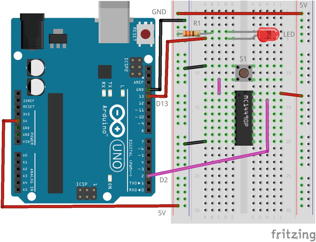
Breadboard layout for the attachInterrupt() sketch
In Figure 3-2, the resistor R1 is 330 Ohms and is there to limit the current drawn by the LED and is connected from the cathode to ground. The anode (the longest lead) is attached to D13 as the built-in LED is not very bright.
Given that switches bounce quite a lot, I suspected that Listing 3-37 was unlikely to work correctly, and indeed, it did not. The LED’s state is at best described as “random,” regardless of what you do with the switch.
In theory, when the switch is pressed or held down, it connects D2 to ground. This registers as a change in state for D2, and the ISR fires to change the state variable to HIGH. After the ISR has finished executing, the loop() code then turns the LED on. When the switch is released, the internal pullup resistors pull pin D2 HIGH again, which registers as a change of state, so the ISR executes again and the state variable toggles to LOW. This then results in the loop() code turning off the LED.
In practice, I have tested this code, and it’s very difficult to get it to be consistent due to switch bounce. It makes and breaks numerous times before settling to a steady state. I’ve seen the LED remain lit while the switch was released and go out when it was pressed. This code needs a good debouncing routine; or, if necessary, a couple of extra components need to be added to the breadboard to debounce the switch in hardware.
I used a hardware solution and added the “MC14490 Hex Contact Bounce Eliminator” chip you can see in Figure 3-2. I connected the switch’s output pin to pin 1, the Ain pin, on the MC14490, and pin 15, the Aout pin, to Arduino pin D2. Once the circuit was debounced, the code worked perfectly. The fully debounced circuit is shown in Figure 3-2. The MC14490 allows up to six switches to be debounced, and they are very cheap on eBay – plus, they debounce on “make” as well as “break.”
Without debouncing of some kind, problems would occur if, for example, the switch changed state only once, so the ISR was called. While the ISR was executing, however short a time that was, interrupts were disabled and, thus, no further interrupts were able to be actioned. However, if other interrupts were received, a flag bit was set each time to show that one or more interrupts had occurred during the execution of the ISR. When the ISR finishes executing and returns to the main code, one instruction would be executed, and then the ISR would be executed again due to the flag bit being set. Regardless of how many interrupts were received during the first ISR’s execution, it would only be executed again once.
If state was LOW and the switch was pressed, then the ISR would change the value of state to HIGH, and the LED would come on. However, if any number of bounces, let’s say 4, occurred while the ISR was executing, then state should have changed four more times, so from HIGH – as currently set by the ISR – to LOW ➤ HIGH ➤ LOW ➤ HIGH, and the LED should remain on.
Unfortunately, those four changes only got recorded as having occurred at least once, not how many actually occurred, so the ISR would execute once and change state from HIGH to LOW and the LED would go off even though the button was still being pressed.
In order for the LED to follow the state of the switch, there must be no bouncing, or the ISR must be executed an even number of times, hence the requirement for a good debouncing function, or my solution in hardware, as it’s almost impossible for a switch to only bounce an even number of times!
The attachInterrupt() function
① EXTERNAL_NUM_INTERRUPTS is defined as 2, in $ARDINC/wiring_private.h, and is the total number of external interrupts available on an ATmega328P. You should note that interruptNum is unsigned here; however, digitalPinToInterrupt() can, if passed an invalid pin number, return NOT_AN_INTERRUPT which is negative. However, this code will still work correctly as NOT_AN_INTERRUPT converts to 255 when passed as -1 to an unsigned variable.
② The supplied pointer to the interrupt function in the sketch is saved in a table. There are EXTERNAL_NUM_INTERRUPTS slots in the table.
③ This sets up the INT0 external interrupt and enables it.
④ This sets up the INT1 external interrupt and enables it.
The attachInterrupt() function is quite simple in operation. It saves the sketch’s function addresses in a table, set up for just this reason, and then, depending on the interrupt requested, sets the bits in the EICRA and EIMSK registers so that the interrupt will fire on the appropriate stimulus.
The real ISR for attachInterrupt()
ISR for the INT0 interrupt
① This one line accesses the user-supplied ISR function in the table and executes it.
The documentation for attachInterrupt() at www.arduino.cc/reference/en/language/functions/external-interrupts/attachinterrupt/ on the Arduino Reference web site has the following to say:
The first parameter to attachInterrupt is an interrupt number. Normally you should use digitalPinToInterrupt(pin) to translate the actual digital pin to the specific interrupt number. For example, if you connect to pin 3, use digitalPinToInterrupt(3) as the first parameter to attachInterrupt().
Inside the attached function, delay() won’t work and the value returned by millis() will not increment as millis() relies on interrupts to count, so it will never increment inside an ISR. Since delay() also requires interrupts to work, it will not work if called inside an ISR – because interrupts are disabled while processing an ISR.
The micros() function will work initially, but will start behaving erratically after 1-2 milliseconds.
However, the delayMicroseconds() function does not use any counter/interrupt, so it will work as normal.
Serial data received while in the function may be lost.
You should declare as volatile any variables that you modify within the attached function. Typically global variables are used to pass data between an ISR and the main program. To make sure variables shared between an ISR and the main program are updated correctly, declare them as volatile.
Generally, an ISR should be as short and fast as possible. If your sketch uses multiple ISRs, only one can run at a time, other interrupts will be executed after the current one finishes in an order that depends on the priority they have.
Regarding the potential loss of serial data received, you should be aware that serial data is copied from the USART to the serial receive buffer under control of an interrupt handler. Obviously, when processing your interrupt function, interrupts are off, but the USART still runs in the background as it is not controlled by the main CPU. There is room in the USART for 2 bytes only, so if your interrupt function takes too long and data are being received by the USART, it will buffer up the first 2 bytes and then suffer a buffer overrun error. Subsequent bytes received will be lost.
Keep the ISR or interrupt functions physically as short as possible. If you must do work as a result of an interrupt, use the ISR or function to simply set a flag, a variable value or similar, and have the main loop() code check it and execute the desired actions.
Do not call delay() or any of the Serial.print() functions from inside an ISR or interrupt function. That way, dragons lie!
All variables you wish to share with the main code should be declared volatile and, if necessary, when being accessed, may require to be wrapped in a “critical section” which means calling noInterrupts() before accessing the shared data and calling interrupts() afterwards This, obviously, is required within the main code, not in the interrupt function.
Finally, don’t enable interrupts within an ISR or interrupt function unless you really, really know what you are doing.
3.5.4 Function detachInterrupt()
The code for the detachInterrupt() function is found in the file $ARDINC/WInterrupts.c and also in Listing 3-41.
This function detaches an interrupt function, in a sketch, from an external interrupt. The function will have been previously attached to the interrupt by a call to the attachInterrupt() function. There isn’t always a need to call detachInterrupt() unless your sketch is finished with the ability to process the appropriate interrupt and wants to prevent any further processing of the interrupt function from taking place.
This function works by disabling the INT0 and/or INT1 interrupt bits in the EIMSK register and blanks out the entry for the function in the function pointer table populated in attachInterrupt().
The detachInterrupt() function
① Passing an invalid pin number to digitalPinToInterrupt() will return NOT_AN_INTERRUPT (-1) which is a signed value, as previously discussed. The detachInterrupt() function will still act correctly in that case and do nothing at all.
② Disable the INT0 interrupt handler from Arduino pin D2.
③ Disable the INT1 interrupt handler from Arduino pin D3.
④ The sketch’s interrupt function pointer is removed from the array of interrupt functions.
The nothing() interrupt handler function
This is where the interruptNumber parameter is the one returned from digitalPinToInterrupt() when called previously when calling attachInterrupt() for this pin.
3.6 Bits and Bobs
This section deals with a few “bits and bobs” – macros which allow you to do bit handling at the lowest level.
3.6.1 Macro bit()
It returns the value of 2b where b is the bit number. For example, calling bit(5) will return 32 as 25 is 32. You will hopefully notice that the returned value is an unsigned long from the initializer 1UL, so there are 32 bits to play with, but remember to number the bits from 0 through to 31.
Example usage of the bit() macro
This will display “2 to the power 10 is: 1024” on the Serial Monitor.
Bits and their values
Bit | Value Returned | Bit | Value Returned | Bit | Value Returned | Bit | Value Returned |
|---|---|---|---|---|---|---|---|
0 | 1 | 1 | 2 | 2 | 4 | 3 | 8 |
4 | 16 | 5 | 32 | 6 | 64 | 7 | 128 |
8 | 256 | 9 | 512 | 10 | 1,024 | 11 | 2,048 |
12 | 4,096 | 13 | 8,192 | 14 | 16,384 | 15 | 32,768 |
16 | 65,536 | 17 | 131,072 | 18 | 262,144 | 19 | 524,288 |
20 | 1,048,576 | 21 | 2,097,152 | 22 | 4,194,304 | 23 | 8,388,608 |
24 | 16,777,216 | 25 | 33,554,432 | 26 | 67,108,864 | 27 | 143,217,728 |
28 | 268,435,456 | 29 | 536,870,912 | 30 | 1,073,741,824 | 31 | 2,147,483,648 |
3.6.2 Macro bitClear()
Example usage of the bitClear() macro
However, there are probably much better ways to achieve this!
3.6.3 Macro bitRead()
Example usage of the bitRead() macro
3.6.4 Macro bitSet()
Example usage of the bitSet() macro
3.6.5 Macro bitWrite()
Example usage of the bitWrite() macro
3.6.6 Macro highByte()
Example usage of the highByte() macro
The code in Listing 3-48 will print “2” on the Serial Monitor. 513decimal is 201hex which converts to 0000 0010 0000 0001binary. The high 8 bits are 0000 0010binary which is 2 in decimal.
3.6.7 Macro lowByte()
Example usage of the lowByte() macro
The code in Listing 3-49 will print “1” on the Serial Monitor. 513decimal is 201hex which converts to 0000 0010 0000 0001binary. The low 8 bits are 0000 0001binary which is 2 in decimal.
3.6.8 Macro sbi()
In order to use this macro, you must include the header file wiring_private.h, as shown in Listing 3-50.
The macro sets the requested bit, in the register, to one. You cannot call this with a value or a variable; it must be one of the lowest 32 I/O registers, as defined in the file $AVRINC/iom328p.h which is included automatically for you by $AVRINC/io.h, itself included by $ARDINC/Arduino.h.
Example sbi() macro call
![]() The two macros described here, the preceding sbi() and the following cbi(), should probably not be used as they may fail to do what is required in some circumstances. This is because the ATmega328P has some of its I/O registers outside the range of addresses that these two instructions can access. Both sbi() and cbi() can only access the lowest 32 of the various I/O registers in the ATmega328P.
The two macros described here, the preceding sbi() and the following cbi(), should probably not be used as they may fail to do what is required in some circumstances. This is because the ATmega328P has some of its I/O registers outside the range of addresses that these two instructions can access. Both sbi() and cbi() can only access the lowest 32 of the various I/O registers in the ATmega328P.
You might get away with it, but then again, you might not. You have been warned. It is especially galling that the compiler doesn’t give any error messages if you do try to access a register that is out of range. Be careful.
3.6.9 Macro cbi()
In order to use this macro, you must include the header file, as shown in Listing 3-51.
The macro clears the requested bit, in the register, to zero. You cannot call this with a value or a variable; it must be a register, as defined in the file $AVRINC/iom328p.h which is included automatically for you by $AVRINC/io.h, itself included by $ARDINC/Arduino.h.
Example cbi() macro call
The definition of PORTB5 (and others from PORTB0 to PORTB7) allows you to refer to the individual bits in the PORTB register. Similar definitions exist for PORTC and PORTD, as well as the three DDRx and PINx registers. All the bits in all the registers are predefined for you when you compile a sketch. This means that you don’t have to use the Arduino Language all the time, especially if there is an ATmega328P feature that isn’t available from the Arduino Language. The Analogue Comparator, for example, as discussed in Chapter 9, must be accessed using the registers directly.