
This chapter investigates the various C++ classes supplied as part of the Arduino Language and which help, in most cases, to make the programmer’s life easier when using features of the Arduino board (and the ATmega328P) such as the Serial interface.
![]() In the remainder of this chapter, I will not be showing all the source code for the various Arduino classes. Some of these classes have a large amount of code, and the book would become very large and unwieldy as a result. I will be explaining the important parts though.
In the remainder of this chapter, I will not be showing all the source code for the various Arduino classes. Some of these classes have a large amount of code, and the book would become very large and unwieldy as a result. I will be explaining the important parts though.
4.1 The Print Class
The Print class is found in the two files Print.h and Print.cpp both located in the $ARDINC directory. A tutorial on implementing your own classes which inherit from Print can be found online at https://playground.arduino.cc/Code/Printclass/.
The Print class will be inherited by descendant classes and provides the ability to call print() and println() in those classes. It is used by, among others, the Serial interface and the Printable class. By far, the vast majority of the functions exposed by this class boil down to internal calls to a virtual function named write() which has to be provided by the descendant class as it is declared pure virtual in the Print class.
String class variables
Data stored in flash memory
char variables and char arrays
int variables
long variables
double variables
Class variables descending from the Printable class
The println() function allows all of the preceding data types, plus void parameters, which simply means a call to println() without passing any parameters. This simply “prints” a linefeed to the interface. A linefeed in this case is a Windows-style linefeed consisting of a carriage return and a linefeed – ASCII characters 13 and 10.
![]() I use “prints” in quotes as the descendant class in the hierarchy will output the bytes as appropriate. The Serial interface, for example, “prints” bytes to a buffer which will then be sent to the USART for transmission, while the LiquidCrystal library class displays the characters on screen. Other interfaces will most likely have their own manner of “printing,” which could mean sending the data down the network cable to the Internet, to a file on an SD card and so on.
I use “prints” in quotes as the descendant class in the hierarchy will output the bytes as appropriate. The Serial interface, for example, “prints” bytes to a buffer which will then be sent to the USART for transmission, while the LiquidCrystal library class displays the characters on screen. Other interfaces will most likely have their own manner of “printing,” which could mean sending the data down the network cable to the Internet, to a file on an SD card and so on.
The Print class virtual functions
① Only the write(uint8_t) is a pure virtual function and, as such, must be implemented by a descendant class. In the file $ARDINC/HardwareSerial.cpp, for example, the write(uint8_t) function sends a single unsigned char to the USART. The Serial interface descends from the Stream class, which itself descends from the Print class; and as long as at least one class in the hierarchy implements the write(uint8_t) function, the code should compile.
② If required, descendant classes may implement this function which should be called to provide a manner of “printing” entire char arrays. The Print class provides a default implementation of this function, which simply sends each character in the array to the write(uint8_t) function.
③ This function defaults to returning zero to indicate that a single call to write() may block. This obviously depends on the interface in use. The descendant classes may wish to reimplement this function if, for example, they use some form of buffering which helps prevent blocking. Other non-zero values indicate that the call to write() may not block. The Serial class has done this in file $ARDINC/HardwareSerial.cpp as it buffers data for transmission, and also for receipt, and uses interrupts to transmit and receive data from/to the buffers.
④ The flush() function is provided for backward compatibility with older versions of the Arduino Language. In the current version, 1.8.5, it is an empty function which does nothing. Classes may reimplement this function if necessary – as the Serial class does.
4.1.1 Class Members
BIN – Defined as the value 2 and used when outputting data in binary, or base 2
OCT – Defined as the value 8 and used when outputting data in octal, or base 8
DEC – Defined as the value 10 and used when outputting data in decimal, or base 10, the default
HEX – Defined as the value 16 and used when outputting data in hexadecimal, or base 16
Print() – Constructor. This does very little other than setting the error flag to show that, so far, no errors have occurred.
size_t print() – Sends data to the output without a trailing newline. It can be used to “print” many different data types.
size_t println() – Similar to print() but terminates the output with a Windows-style carriage return and linefeed.
int getWriteError() – Returns any error code from a write() function call.
void clearWriteError() – Clears any existing write error code.
size_t write(const char *str) – May be overridden by descendant classes. This is the default function to “print” a character array.
size_t write(const uint8_t *buffer, size_t size) – May be overridden by descendant classes. This function “prints” an array, of known size, of unsigned characters.
size_t write(const char *buffer, size_t size) - Calls the write(const uint8_t *buffer, size_t size) function to “print” a signed character array.
int availableForWrite() – May be overridden by descendant classes. This function returns zero if the descendent class’s write() function will, or may, block.
void flush() – May be overridden by descendant classes. This function flushes the output buffer to ensure that all data are correctly written.
![]() If your own class which inherits from the Print class has defined, as it must, the pure virtual function write(), then your class can send bytes to whatever it needs to. If your class header file includes
If your own class which inherits from the Print class has defined, as it must, the pure virtual function write(), then your class can send bytes to whatever it needs to. If your class header file includes
using Print::write;
it will be also able to use the Print class’s functions which write other data types. As these all call down to the virtual write() function eventually, it will call your class’s own write() function, so you get the ability to “print” data types other than a single unsigned char, for free.
4.1.2 Using the Print Class
An example of the use of the Print class is in the library for the LiquidCrystal display as supplied with the Arduino IDE. The library can be found in the two files LiquidCrystal.h and LiquidCrystal.cpp located in the $ARDBASE/libraries/LiquidCrystal/src directory. The following description includes only the relevant parts of the code – those which show the use of the Print class by the LiquidCrystal library.
LiquidCrystal.h
① When writing a library, you are responsible for including all the required header files. The IDE doesn’t do this for you anymore! The Print.h file is required as we are inheriting from the Print class.
② The LiquidCrystal class inherits from the Print class. This gives objects of the LiquidCrystal class the ability to call print() and println() which are member functions in the base class, Print.
③ Descendant classes, inheriting from Print, must define the write() function as it is declared as pure virtual in the Print class.
④ Descendant classes don’t need to redefine all the other write() functions which “print” different data types if they use this line of code. This gives access to all the functions in the Print class, but each will call out to the descendant class’s write() function.
LiquidCrystal’s write() function
LiquidCrystal’s send() function
If we ignore the code that’s setting up the pins to enable the sketch to write to the display, we eventually end up at the calls to write8bits() and write4bits(). LiquidCrystal displays can be configured to receive 8 bits of data from the Arduino, or just 4 bits – some displays only cope with 4 bits. For this explanation, I shall concentrate on 8-bit displays – the main difference being that 4-bit displays need two data writes to receive a character, while 8-bit displays get the whole character in one write.
LiquidCrystal’s write8bits() function
That’s all there is to it! The passed data, in parameter value, is used to set the bits on the eight data lines for the display. (Other displays can use the I2C interface which uses a lot fewer data lines; see the LiquidCrystal_I2C library for details.)
The preceding code sets a data pin HIGH if the corresponding bit in value is a 1binary and LOW if it is a 0binary. Once all eight data pins have been set correctly, pulseEnable() is called to, ahem, pulse the enable pin for the display and latch the data into the display whereupon it will be “printed” to the screen.
The HelloWorld example sketch
① We must include the library’s header file; normally this is done with the Sketch ➤ Include Library ➤ LiquidCrystal menu option. In my case, this line was included twice by the menu. I removed the extra line.
② Here, some constants are defined for the various pins that the LiquidCrystal objects require. In this case, we are only using 4 bits of data, not 8. The rs pin is the display’s register select pin, en is the enable pin – used to latch data onto the display – and d4, d5, d6, and d7 are the four data pins.
③ An object of type LiquidCrystal is declared and initialized here. The various pins to be used are passed in the constructor. On return, lcd is our object through which we can manipulate the display.
④ The display is further initialized to two rows of 16 characters. Other options are available. My own display has four rows.
⑤ This is what we have been working up to. The lcd object can call the Print class’s print() function. Within the Print class, the function which prints an array of char will be called, and that will pass each character to the LiquidCrystal class’s write() function. The characters in the array are then printed to the display using the code in Listings 4-3 through 4-5.
⑥ The loop() code just sets the cursor to the start of the second line (rows number from 0) and uses the print() function to print the number of millis() that have passed since the sketch began. Here the value to be printed is an unsigned long, and within the Print base class, that call will work its way down to the LiquidCrystal class’s write() function in the manner described earlier.
4.2 The Printable Class
In this case, the PrintTo() function would handle the streaming of the aPerson object’s data. For example, it might print the name, address, and phone numbers of the specific person. We are, of course, assuming that aPerson is an object of some class that describes a person.
The Printable.h header file
① This is a forward declaration of the Print class. It can be done without including the Print.h header file as we don’t need anything from it within this file, other than the fact that it exists and is a class named Print. In the case being examined here, the print.h header isn’t that large, so the time saved by not having to read it in is insignificant. Other class header files may not be so forgiving.
- ② The Printable class cannot be instantiated by itself as it has only pure virtual members. It must be used as an ancestor class, and the descendant classes must implement the printTo() function. To use the Printable class, therefore, your classes have to
Include the Printable.h header file
Inherit from the Printable class
Implement a function named printTo which takes a reference to a Print class and returns a size_t value which is the number of bytes printed
That’s all there is to it. Your class can now be printed over the Serial interface, or similar, provided that the specific interface inherits from the Print class.
4.2.1 An Example Printable Class
The source code shown in Listings 4-8 and 4-9 is that of a very simple class which has been set up to allow itself to be sent over, for example, the Serial interface. For a more useful, but more complicated, example, have a look at the files $ARDINC/IPAddress.h and $ARDINC/IPAddress.cpp which are used by Arduino boards that have, for example, Ethernet interfaces built in.
Printable example class header
Printable example class implementation
![]() In the preceding constructors, the initialization of the member variables might look strange; however, I’m reliably informed by those in the know about C++ that this is deemed the correct way to initialize member variables. Who am I to argue?
In the preceding constructors, the initialization of the member variables might look strange; however, I’m reliably informed by those in the know about C++ that this is deemed the correct way to initialize member variables. Who am I to argue?
We can see from the preceding code that the printTo() function accepts a Print class object, which is required to be a descendant of a Print class, and calls its print() function three times passing over data from the private members of the class. The function returns the number of bytes printed, which is a requirement.
Printable example class usage
If you upload the preceding code to an Arduino board, then you should see “Dunbar, Norman + Dunbar, Alison” written back to the serial monitor – over and over again. You can, if you wish, substitute your own name in the code shown in Listing 4-10.
It is not mandatory to use Serial. Any ancestor of a Print class will suffice. In the previous discussions, we saw how the LiquidCrystal library descended from Print which means that the me and wife objects in the preceding code could be passed to a LiquidCrystal class object, such as lcd.
4.3 The Stream Class
The Stream class is the base class which defines the data reading functions (e.g., Serial.read()). Stream supplies the reading features complementary to the Print class’s writing features.
The Stream class’s pure virtual functions
① The available() function is required to inform the descendant class, Serial, for example, that the underlying stream has data available to be read. The function returns the number of bytes that have already been received by the underlying stream but which have yet to be read by the sketch.
② The read() function is implemented to allow the descendant classes to physically read the available data. This function will remove the data it reads from the input stream.
③ The peek() function is implemented to allow the descendant classes to take a sneaky peek at the available data, but in a nondestructive manner. The data may subsequently be read by the read() function.
As Stream descends from the Print class, any class that inherits from Stream also inherits the features of the Print class. This will require the descendant class to implement the pure virtual function write() from the Print class, in addition to the requirements of the Stream class.
HardwareSerial – The standard Serial interface.
USBAPI – Serial interface for the Leonardo boards. These use USB serial as opposed to the ATmega328P’s TX and RX pins.
Client – Part of the software for the various Ethernet shields.
Ethernet – A networking library.
SD – A third-party library for accessing SD cards.
4.3.1 Class Members
The Stream class’s LookaheadMode enumeration
Stream() – Constructor. It sets the default timeout to one second (1000 milliseconds). The timeout is used in many of the following functions to limit the scanning process – to prevent code hangups or blocking if the data in the stream, for example, has not fully arrived.
void setTimeout(unsigned long timeout) – Sets the maximum timeout, in milliseconds, to wait for stream data.
unsigned long getTimeout(void) – Returns the current timeout for the stream.
int available() – This function must be overridden in descendant classes. It returns the number of bytes which have been received by the stream, but which have yet to be read by the sketch.
bool find(char *target)
bool find(uint8_t *target)
bool find(char *target, size_t length)
bool find(uint8_t *target, size_t length)
bool find(char target)
bool findUntil(char *target, char *terminator)
bool findUntil(uint8_t *target, char *terminator)
bool findUntil(char *target, size_t targetLen, char *terminate, size_t termLen)
bool findUntil(uint8_t *target, size_t targetLen, char *terminate, size_t termLen)
long parseInt(LookaheadMode lookahead = SKIP_ALL, char ignore = NO_IGNORE_CHAR)
float parseFloat(LookaheadMode lookahead = SKIP_ALL, char ignore = NO_IGNORE_CHAR)
int peek() – Returns characters from the stream without removing them from the internal buffer for the stream.
int read() – Returns characters from the stream and removes them from the internal buffer for the stream.
The following functions return the number of characters read from the stream while copying the data read into a buffer. If a timeout occurs, -1 will be returned, and the contents of the buffer will be undefined. Only length characters maximum will be copied into the buffer. If no valid data are found, then zero will be returned.
size_t readBytes( char *buffer, size_t length)
size_t readBytes( uint8_t *buffer, size_t length)
size_t readBytesUntil( char terminator, char *buffer, size_t length)
size_t readBytesUntil( char terminator, uint8_t *buffer, size_t length)
String readString()
String readStringUntil(char terminator)
In the Stream class, the vast majority of the public functions eventually find their way down to the descendant class’s read(), peek(), or available() function. For this reason, I will not be describing all of the preceding functions – I suspect you would get bored very quickly – only the ones which do the actual work.
Various Stream class cascading find() functions
① Starting with a simple find() with a single char array parameter, it does nothing except call down to findUntil() passing a few more parameters. FindUntil() is shown in Listing 4-14.
② This is a different find() function which takes an additional length parameter to limit the search to that number of characters. Again, it passes control down the ladder to the same findUntil() as noted earlier.
Various Stream class cascading findUntil() functions
① This version of findUntil() accepts a pair of parameters, so is not called from the find() functions in Listing 4-14. It does, however, pass control down to the same findUntil() as the find() functions do. Nearly there! This variant ends the search at the given terminator character or string.
② Here we are, finally – perhaps. We have reached the findUntil() function that everyone eventually gets to. Regardless of which find() or findUntil() we originally called, here is where we arrive.
③ If the terminator is NULL, then we have arrived from find() (or perhaps the first findUntil()). In this case, we create a MultiTarget array in variable t, with a single entry, and call yet another function, findMulti(), to do the actual searching.
④ If the terminator is not NULL, we have been passed some text to use as the end of search marker. In this case, we create a MultiTarget array in variable t, with a pair of entries, and again call findMulti() to do the actual searching.
The MultiTarget structure is defined in Stream.h as a protected structure, alongside the findMulti() function; and so, as internal-only helpers, they are not described here.
One of the readBytes() functions
① All of the various read() functions call out to the protected function timedRead(). That function, although protected, is quite small and is discussed in Listing 4-16 as it does require more investigation as it uses timeouts and it is where your Stream descendant class finally gets accessed! The purpose is to return a single character from the underlying stream within a given timeout period.
The protected timedRead() function
① The function has to use the millis() counter because calling delay() would not act as a timeout, but more of a block on any processing. The timeout is required to prevent the sketch hanging up, or blocking, because the underlying stream hasn’t sent enough data or is running too slowly. The error code passed back can be used to loop around, if necessary, and try reading data again.
② This do loop will execute for as long as the timeout has not expired.
③ This is where your class gets to earn a living. The Stream class is now, finally, calling down to the descendant class’s implementation of the read() function to fetch a single character from the stream.
④ We have received a valid character, so we can exit the do loop and return the character to the calling function.
⑤ On return from the descendant class’s read() function, if nothing was retrieved, the tail end of the loop checks that the timeout has not yet expired and, if not, will resume the do loop for another iteration.
⑥ If the timeout expired and we fell through the bottom of the do loop, -1 is returned to indicate the fact that we couldn’t read any data from the underlying stream within the current timeout period.
4.4 The HardwareSerial Class
The Serial interface, in the Arduino Language, is an instance of a class known as HardwareSerial and provides the ability to read and write from the hardware serial port built into the ATmega328P. Other AVR microcontrollers such as the Mega 2560 have more than one hardware serial port, up to four in some devices. Only the code relating to the Uno’s Serial port will be discussed here as the others are very similar.
Other devices have serial ports that connect directly to the USB port – the Leonardo, for example. These boards are not discussed here.
$ARDINC/HardwareSerial_private.h where the constructor and the USART Receive Complete interrupt handler helper function _rx_complete_irq() can be found.
$ARDINC/HardwareSerial.cpp where most of the public functions are implemented, alongside the USART Data Register Empty interrupt handler helper function _tx_udr_empty_irq().
$ARDINC/HardwareSerial0.cpp where the actual interrupt handlers USART_RX_vect() and USART_UDRE_vect() are found. These two, when fired, call out to _rx_complete_irq() and _tx_udr_empty_irq(), respectively, to do the actual work. This is also the file where the instantiation of Serial as an instance of the HardwareSerial class is carried out.
The HardwareSerial class inherits from the Stream class and from Stream’s ancestor class, Print, and this inheritance is the reason that the Serial object can read from and write to the ATmega328P’s USART device. The USART is described in detail in Chapter 9, Section 9.3, “USART.”
4.4.1 Interrupt Handlers
The HardwareSerial class has two interrupt handlers, one of which will be fired whenever the USART receives a single byte, the “USART Receive Complete interrupt.” The other will fire whenever the USART’s transmit buffer is empty and ready to be reloaded with the next byte to be transmitted. This is the “<<”USART Data Register Empty interrupt.”
The two interrupt handlers are created simply to call the two helper routines. Both are implemented in the file $ARDINC/HardwareSerial0.cpp as the functions _rx_complete_irq() and _tx_udr_empty_irq().
In the code listings that follow, only those parts relevant to the ATmega328P are listed.
4.4.1.1 USART Receive Complete Interrupt
USART Receive Data interrupt handler
USART Receive Data interrupt helper
① This line of code checks to see if the character received had a parity error. If not, processing will be allowed to continue.
② The received byte is read from the USART Data Register UDR0. This clears the data received flag, RXC0 in register UCSR0A, and readies the USART to receive the next byte. The USART has a 2-byte internal buffer which, if it fills and another character is received, causes an error.
③ The receive buffer head pointer is advanced by 1 byte. This might cause it to wrap around to the start again as this is a circular buffer. This new position is where the just received byte will be stored.
④ If the new receive buffer head pointer is not yet the same as the current tail pointer, the byte received can be stored and the head pointer updated to the most recently stored byte in the receive buffer. If, on the other hand, the two pointers are equal, the byte just received is quietly lost.
⑤ If there was a parity error, then the byte must still be read from the USART Data Register UDR0. This will clear the data received flag, RXC0 in register UCSR0A. The character read is discarded and not written to the buffer.
![]() The head pointer is the first free location in the buffer where new received data will be stored. The tail pointer is the next data byte to be read by the sketch. If the head pointer equals the tail pointer, then the buffer must be full, and there is nowhere to store any further data without overwriting currently unread data.
The head pointer is the first free location in the buffer where new received data will be stored. The tail pointer is the next data byte to be read by the sketch. If the head pointer equals the tail pointer, then the buffer must be full, and there is nowhere to store any further data without overwriting currently unread data.
4.4.1.2 USART Data Register Empty Interrupt
USART Data Register Empty interrupt handler
USART Data Register Empty interrupt helper
① The next byte to be transmitted is retrieved from the tail end of the transmit buffer. As this is an interrupt handler, then interrupts must be enabled which is only true when there are data in the transmit buffer ready to be sent through the USART.
② The buffer tail pointer is updated to point at the next character in the buffer. This may cause it to wrap around to the start again.
③ The next byte to be transmitted is stored in the USART Data Register UDR0, in the case of the ATmega328P. Storing a byte here automatically starts the transmission – when the previous byte has been transmitted.
④ The Transmit Complete (TXC0) flag is cleared in register UCSR0A. This bit is automatically cleared when the USART Transmit Complete interrupt fires, but the Arduino doesn’t use that interrupt – it uses the USART Data Register Empty interrupt instead, so the code must clear it manually. This line of code also preserves the U2X0 and the MPCM0 flags – the USART Double Speed and Multi-processor Communications flags. (See the ATmega328P data sheet for details.)
The clearing of the TXC0 bit looks strange. It is already set to a 1binary; so if it is ANDed with another 1binary, it will remain as it is. Then when written back to UCSR0A, it will clear it to zero. Weird? Really weird?
The other bits and flags in the UCSR0A register will be cleared to 0binary by this line of code, unless they too need to be cleared – by writing a 1binary of course. You should note that the bits for Frame Error, FE0; Data Overrun, DOR0; and Parity Error, UPE0, must all be 0binary when writing any value to the UCSR0A register. See the data sheet for details.
⑤ If the transmit buffer’s head and tail pointers are the same, then it is empty, interrupts are disabled, and this stops transmission attempts.
The choice of interrupt handler is interesting here. Why not use the USART Transmit Complete interrupt rather than the USART Data Register Empty interrupt? There is much confusion about this it seems; however, the answer is relatively simple.
The UDR0 register can be empty while the transmission is still in progress. The register contains a single byte, or 8 bits. The USART has to transmit a frame of more than 8 bits – there are the start and stop bits, the parity bit if required, as well as the 8 bits of data – so the USART Data Register Empty interrupt will fire and allow the next byte to be loaded into UDR0 while the previous byte is still in the process of being transmitted. This should increase performance a tiny bit, depending on how many actual bits are in a frame.
4.4.2 Class Functions and Macros
The HardwareSerial class defines the following in the file $ARDINC/HardwareSerial.h.
4.4.2.1 Macro SERIAL_TX_BUFFER_SIZE
Definition of SERIAL_TX_BUFFER_SIZE
Remember to make the new value a power of two.
4.4.2.2 Macro SERIAL_RX_BUFFER_SIZE
Definition of SERIAL_RX_BUFFER_SIZE
Don’t forget, the new value needs to be a power of two.
4.4.2.3 Typedefs tx_buffer_index_t and rx_buffer_index_t
Definition of tx_buffer_index_t
Definition of rx_buffer_index_t
4.4.2.4 Serial Communications Parameters
Configuration parameters for the Serial.begin() function
Define | Value | Description |
|---|---|---|
SERIAL_5N1 | 0x00 | 5 bits, no parity, 1 stop bit |
SERIAL_6N1 | 0x02 | 6 bits, no parity, 1 stop bit |
SERIAL_7N1 | 0x04 | 7 bits, no parity, 1 stop bit |
SERIAL_8N1 | 0x06 | 8 bits, no parity, 1 stop bit (Default) |
SERIAL_5N2 | 0x08 | 5 bits, no parity, 2 stop bits |
SERIAL_6N2 | 0x0A | 6 bits, no parity, 2 stop bits |
SERIAL_7N2 | 0x0C | 7 bits, no parity, 2 stop bits |
SERIAL_8N2 | 0x0E | 8 bits, no parity, 2 stop bits |
SERIAL_5E1 | 0x20 | 5 bits, even parity, 1 stop bit |
SERIAL_6E1 | 0x22 | 6 bits, even parity, 1 stop bit |
SERIAL_7E1 | 0x24 | 7 bits, even parity, 1 stop bit |
SERIAL_8E1 | 0x26 | 8 bits, even parity, 1 stop bit |
SERIAL_5E2 | 0x28 | 5 bits, even parity, 1 stop bit |
SERIAL_6E2 | 0x2A | 6 bits, even parity, 1 stop bit |
SERIAL_7E2 | 0x2C | 7 bits, even parity, 1 stop bit |
SERIAL_8E2 | 0x2E | 8 bits, even parity, 1 stop bit |
SERIAL_5O1 | 0x30 | 5 bits, odd parity, 1 stop bit |
SERIAL_6O1 | 0x32 | 6 bits, odd parity, 1 stop bit |
SERIAL_7O1 | 0x34 | 7 bits, odd parity, 1 stop bit |
SERIAL_8O1 | 0x36 | 8 bits, odd parity, 1 stop bit |
SERIAL_5O2 | 0x38 | 5 bits, odd parity, 2 stop bits |
SERIAL_6O2 | 0x3A | 6 bits, odd parity, 2 stop bits |
SERIAL_7O2 | 0x3C | 7 bits, odd parity, 2 stop bits |
SERIAL_8O2 | 0x3E | 8 bits, odd parity, 2 stop bits |
Default Serial.begin() function
You can see it simply calls the overloaded begin() function – see Listing 4-29 – with the required two parameters.
4.4.2.5 Macro HAVE_HWSERIAL0
Defining Serial as extern.
Actual definition of Serial
The Serial variable is an object of type HardwareSerial. The following functions are exposed by this class.
4.4.2.6 Constructor HardwareSerial()
HardwareSerial constructor()
① This constructor is using the “colon” manner of initializing the member variables from the parameters passed to the constructor.
② All the initialization has been done; the body of the constructor is empty.
This manner of initializing an object in the constructor is considered the correct method in modern versions of the C++ standards.
4.4.2.7 Function begin(unsigned long baud)
This function is called to commence serial communications at the specified baud rate, with a config of SERIAL_8N1 for 8-bit, no parity, and 1 stop bit communications. This function calls the overridden begin(unsigned long, uint8_t) function in Listing 4-29, passing the desired baud rate and SERIAL_8N1.
4.4.2.8 Function begin(unsigned long, uint8_t)
The begin() function is called to initialize serial communications at the desired baud rate and configuration. Listing 4-29 shows the code that performs the actual initialization. There are other overloaded versions of the begin() function which take fewer parameters; however, they all eventually arrive at the following code.
The HardwareSerial::begin() function
① This assumes that high-speed communications will be used and sets bit U2X0 in the UCSR0A register to enable high-speed communications mode. All other bits are cleared. The baud_setting variable here is not the actual baud rate desired – that’s in baud. The calculation here is working out a value for the USART Baud Rate Register 0 or UBRR0, which will define the actual baud rate for communications.
② If an older board is in use, with a clock speed of 16 MHz, and a baud rate of 57600 is chosen, or if the baud_setting calculated above is 4096 or higher on any board, then the high-speed mode is disabled and baud_setting recalculated for the low-speed mode. There is a comment in the code which states that this line is a
Hardcoded exception for 57600 for compatibility with the bootloader shipped with the Duemilanove and previous boards and the firmware on the 8U2 on the Uno and Mega 2560. Also, The baud_setting cannot be > 4095, so switch back to non-u2x mode if the baud rate is too low.
③ UBRR0 is a 12-bit register – well, it’s a 16-bit register, but the top 4 bits of the high byte are ignored. It is used as a counter for the serial clock generator. Every time that it counts down to zero, it will be reset to the value calculated in baud_setting. This is the baud rate generator for the USART. The calculated baud_setting is split into two parts and loaded into the high and low bytes of the UBRR0 register. 16-bit registers in the ATmega328P must, usually, be loaded high byte first and then low byte.
④ The _written flag is set whenever a byte is transmitted. This is used as a simple shortcut, so that calls to flush() can return quickly if no actual transmissions have taken place.
⑤ The desired data width, parity, and stop bits are set up here. The default is 8 bits, no parity, and 1 stop bit.
⑥ These two lines enable data receipt and transmission. This has the effect of removing Arduino pins D0 and D1 from general use – they are now in the care of the USART.
⑦ The final two lines enable the interrupts for receiving and transmitting data. This is why the Serial interface cannot be used within an interrupt handler because interrupt handlers disable interrupts while executing. The interrupts enabled are the USART Receive Complete interrupt and the USART Data Register Empty interrupt.
However, both the Arduino and the data sheet usually agree on the final, integer, result. This applies to both low- and high-speed communications calculations. Figures 4-1 and 4-2 show the calculated values and error rates.
In addition to the slightly different calculation, the Arduino code works with unsigned integers, unsigned long and uint16_t, while the data sheet appears to calculate using floating point arithmetic with rounding up or down carried out at the very end. At least, that’s the only way I could get the same answers as the data sheet. I am therefore of the opinion that the data sheet is incorrect!
A similar discrepancy exists between how the Arduino and the data sheet calculate low-speed UBBR0 settings and also error rates for the various settings. (See in the following.)
4.4.2.8.1 Notes on Baud Rate Calculations
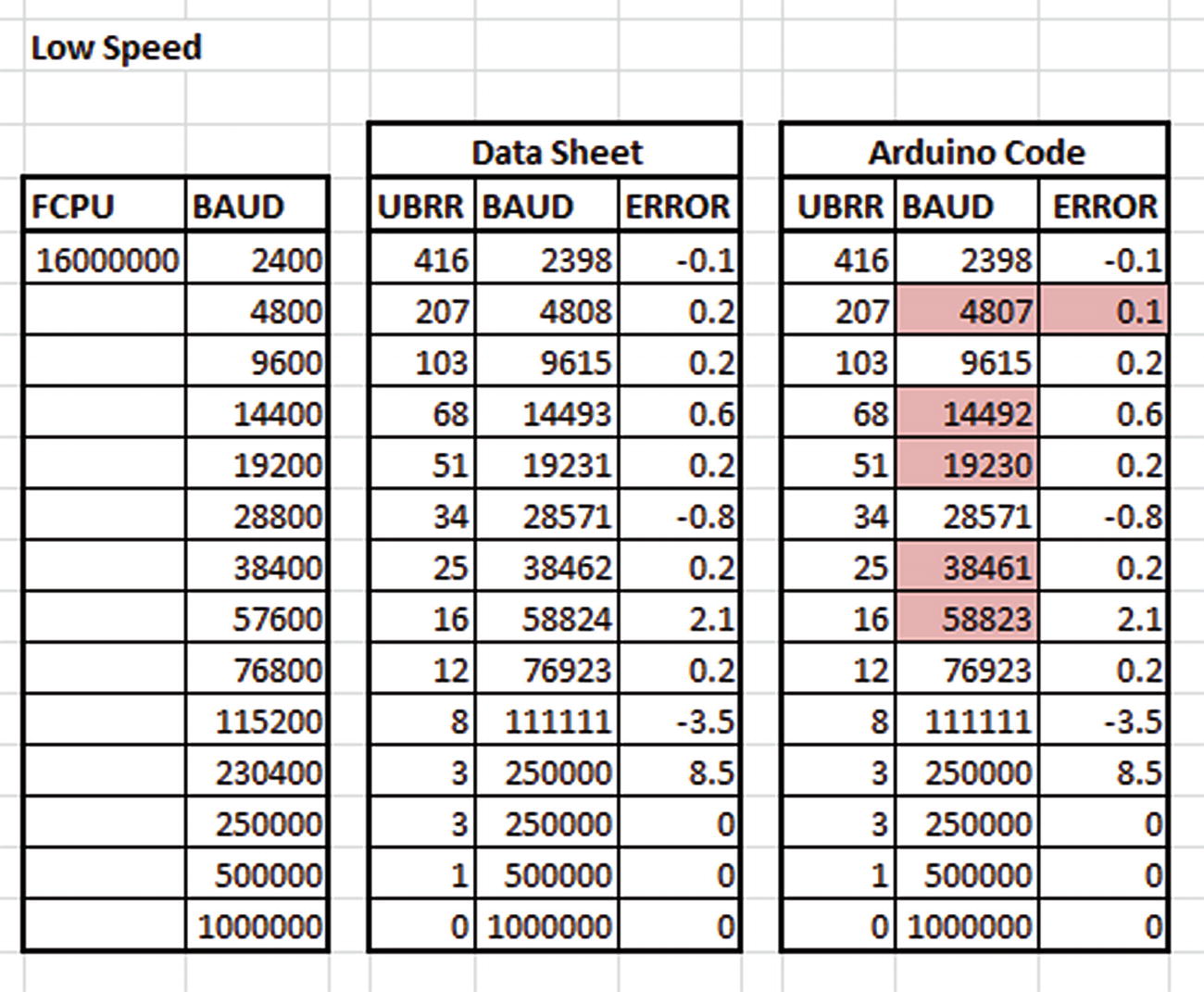
Low-speed baud rate calculations
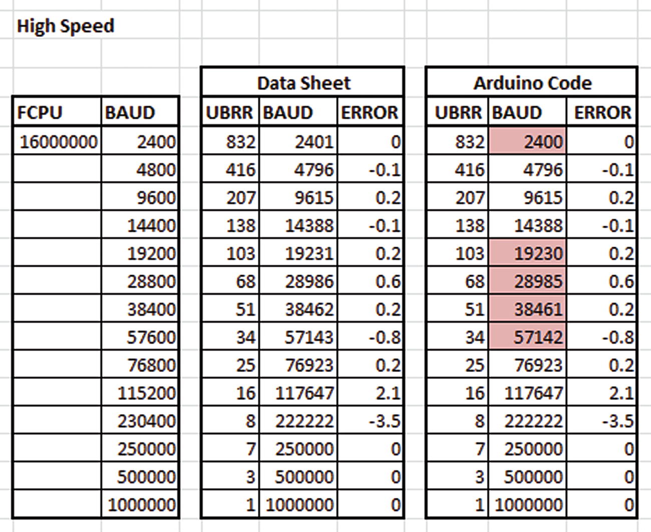
High-speed baud rate calculations
The clock speed for the AVR microcontroller is 16 MHz.
The data sheet figures use floating point calculations and are rounded at the very end. Rounding is up or down according to where the fractional parts are in relation to 0.5 – equal or higher rounds up and lower down.
The data sheet baud rates are again calculated from the floating point values with rounding at the end. This, to my mind at least, is incorrect as the value in UBRR0 cannot possibly be a floating point value!
The Arduino figures use unsigned integer values throughout with truncation downward as opposed to rounding up or down as appropriate.
The difference between floats with fractions and unsigned integers accounts for the variances highlighted – even when it appears that the data sheet and the Arduino code have the same UBRR0 figures.
This means that the baud rate, in low-speed mode, ranges from 16 MHz/(16 * (0 + 1)) which is 1,000,000 baud down to 16 MHz/(16 * (4,095 + 1)) which equals 244 baud.
This means that the baud rate, in high-speed mode, ranges from 16 MHz/(8 * (0 + 1)) which is 2,000,000 baud down to 16 MHz/(8 * (4,095 + 1)) which equals 488 baud.
![]() You should be aware that you are not limited to the baud rates in the preceding images. The Arduino code will accept any value for the requested baud rate and attempt to calculate a suitable value for UBRR0.
You should be aware that you are not limited to the baud rates in the preceding images. The Arduino code will accept any value for the requested baud rate and attempt to calculate a suitable value for UBRR0.
The value written to UBRR0 is used as a divider of the system clock and can be anything between 0 and 4095. It is not the baud rate. It is used to calculate the correct timings to give the required baud rate by prescaling the system clock.
4.4.2.8.2 Notes on Baud Rate Errors
Just about all desired baud rates are not quite exactly achievable. This is because calculating the UBRR0 value loses accuracy when the fractional parts are lost – registers don’t have room for fractions after all. This means that the USART may not quite be running at exactly the baud rate requested by the sketch.
![]() The new ATmega328P data sheet from Microchip appears to have a bug in the calculation. It states that the error rate is “Error% = (Actual Baud / Desired Baud -1)2 100.”
The new ATmega328P data sheet from Microchip appears to have a bug in the calculation. It states that the error rate is “Error% = (Actual Baud / Desired Baud -1)2 100.”
In this formula, instead of a multiplication by 100, the 100 just sits there by itself while the result of preceding division is squared. The superscripted “2” in the data sheet could be a footnote number, but as there is only a single footnote on the page, this doesn’t look likely. The old Atmel data sheet has the correct formula.
The data sheet figures for the error rate appear to be rounded to a single decimal place at the end of the calculation.
The data sheet advises avoiding those baud rates where the calculated error rate is plus or minus 0.5% or higher.
The data sheet figures should be taken with a pinch of salt! You cannot count with register values holding floating point values – unless you are using a floating point unit (FPU) of course, but the AVR microcontroller doesn’t have one.
4.4.2.8.3 Notes on Low- and High-Speed Communications
According to the data sheet, setting U2X0 in register UCSR0A to 1binary will reduce the divisor of the baud rate divider from 16 to 8 effectively doubling the transfer rate for asynchronous communication.
It goes on to state that
Setting this bit will reduce the divisor of the baud rate divider from 16 to 8, effectively doubling the transfer rate for asynchronous communication. Note however that the Receiver will in this case only use half the number of samples (reduced from 16 to 8) for data sampling and clock recovery, and therefore a more accurate baud rate setting and system clock are required when this mode is used. For the Transmitter, there are no downsides.
So it appears that this bit may affect data receipt while not affecting data transmission.
4.4.2.9 Function end()
The HardwareSerial::end() function
① Any data currently in the transmission buffer is allowed to complete its transmission.
② The USART transmit and receive functions are disabled. Pins D0 and D1 return to normal Arduino input/output mode.
③ Transmit and Receive interrupts are disabled.
④ The receive buffer is emptied ready for subsequent receipt of data. The data may not have been read by the sketch yet, but it is now gone.
4.4.2.10 Operator bool()
The bool() function, in Listing 4-31, will return true if the specified serial port is available. It is called, for example, as in if (Serial) ..., and will only ever return false if called in a sketch which is running on a Leonardo board, for example, and the USB CDC serial connection is not yet ready.
The HardwareSerial::operator bool() function
The preceding code is from a standard Arduino, obviously!
4.4.2.11 Function available(void)
The HardwareSerial::available() function
The head is where the next byte received by the USART will be placed; the tail is the next byte to be read into the sketch. The difference between the two is the number of bytes available. The preceding calculation accounts for any wraparound that takes place when the addition of new bytes to the buffer by the USART causes the head pointer to point back at the start of the buffer while the tail pointer is still at a (now) higher address.
So there are 14 bytes of data not yet read by the sketch. These are in the buffer at addresses 155–163 and bytes 100–105, which, if you use your fingers like I just did, is exactly 14 bytes. Remember the tail pointer is the first byte to be read from the buffer and passed to the sketch, while the head pointer is where the next byte read in from the USART will be stored – it is the first free location in the sketch’s receive buffer.
4.4.2.12 Function peek(void)
The HardwareSerial::peek() function
① If the head and tail are equal, there’s nothing in the buffer. An invalid character code, -1, is returned.
② The character at the tail end of the buffer is returned, without changing the tail pointer.
4.4.2.13 Function read(void)
The HardwareSerial::read() function
① If the head and tail are equal, there’s nothing in the buffer. An invalid character code, -1, is returned.
② The next, unread, character is extracted from the buffer.
③ The tail pointer is adjusted to the next character in the buffer, which may cause the tail pointer to wrap around to the first character in the buffer.
④ The extracted character is returned to the sketch.
4.4.2.14 Function availableForWrite(void)
The HardwareSerial::availableForWrite() function
① The transmit buffer’s head and tail pointers will be copied to these two variables, so they are declared with the same data type as the actual head and tail pointers for the buffer.
② Wrapping these two lines in TX_BUFFER_ATOMIC is necessary if the buffer size is bigger than 256 bytes as reading an 8-bit value is atomic – cannot be interrupted – but reading a 16-bit value could be interrupted, and the value may be updated in between reading the low and high bytes. The TX_BUFFER_ATOMIC macro is defined as shown in Listing 4-36.
The protected code block simply copies the current values for the head and tail pointers into the two local variables. The tail pointer is the next location in the sketch’s transmit buffer that will be copied to the USART’s transmit register, while the head pointer is where the sketch will store the next byte sent from the sketch.
③ If the head is ahead of the tail, this calculation returns the bytes between head and tail. If head equals tail, then the buffer is empty, and this calculation returns SERIAL_TX_BUFFER_SIZE - 1.
④ If the head has wrapped back to the start of the buffer and is now behind the tail, this calculation returns the difference between them accounting for the wraparound.
The TX_BUFFER_ATOMIC macro
ATOMIC_BLOCK(ATOMIC_RESTORESTATE) is from the AVRLib and means that whatever state the interrupts were before this block, they should be restored after the block. The block will disable interrupts for the duration.
If the buffer size is less than 256 bytes, the TX_BUFFER_ATOMIC macro expands to nothing as no special handling is required for transferring 8-bit values – they cannot be interrupted.
4.4.2.15 Function flush(void)
The flush() function in Listing 4-37 overrides the virtual function in the ancestor class Print and ensures that any data currently in the process of being transmitted is allowed to continue until completion. This empties the sketch’s transmit buffer and ensures that the entire contents are, indeed, transmitted.
The HardwareSerial::flush() function
① If we have never transmitted a byte, since Serial.begin(), then there is no need to flush. This special check is needed since there is no way to force the TXC0 – transmit complete – bit to 1binary during initialization of the USART which could cause flush() to block forever if called when no data had ever been transmitted.
- ② The while loop will execute as long as the USART Data Register Empty interrupt remains enabled or if data is currently being transmitted by the USART. The comment at the bottom of the function shows the conditions that will be in force when the while loop exits:
The sketch’s transmit buffer is empty.
The transmit complete bit, TXC0, in the UCSR0A register has been set.
The UDRIE bit in UCSR0B is clear to disable the USART Data Register Empty interrupt.
③ If global interrupts are currently disabled but the USART Data Register Empty interrupt is still enabled, then we must still have data in the transmit buffer waiting to be sent.
④ This line explicitly calls the helper function for the USART Data Register Empty interrupt handler if the UDR0 register is currently empty and waiting for another byte.
In other words, the preceding code ensures that even if global interrupts are not enabled, as long as data remains to be transmitted to the USART and beyond, it will indeed be transmitted.
4.4.2.16 Function write(uint8_t)
This function overrides the virtual one in the ancestor class Print and defines how a single unsigned char will be transmitted to the Serial interface. The write() function is split into two separate parts. The first part, the code which follows in Listing 4-38, deals with those occasions when both the transmit buffer in the sketch and the USART Data Register, UDR0, are also empty.
Rather than adding the byte to be transmitted to the sketch’s transmit buffer and waiting for the interrupt handler to forward it to the USART, the code in Listing 4-38 cuts out the middleman and writes the byte directly into the USART Data Register for transmission. The function then returns the number of bytes written – which will always be one.
The HardwareSerial::write() function
① This flag is used by flush() to determine if anything has been written yet, so it must be set any time a byte is supplied to be transmitted. In flush() – see Listing 4-37 – this flag is used as a “quick exit” as it tells flush() whether or not it has work to do.
② This is a performance shortcut to load the passed byte directly into the USART Data Register if the sketch’s transmit buffer is empty – _tx_buffer_head equals _tx_buffer_tail – and the USART Data Register is also currently empty. This reduces overhead and makes higher baud rates more reliable.
③ The comment above this line explains it all. The code must be careful to not get interrupted, so is wrapped in an atomic block which will disable interrupts if necessary, make the required changes, and re-enable interrupts if they were previously enabled. The ATOMIC_BLOCK and ATOMIC_RESTORESTATE macros are defined in the depths of the AVRLib code.
④ The code here simply writes the data byte to the USART Data Register ready to be transmitted.
⑤ This line updates the USCR0A register to preserve the state of the high-speed (U2X0) and Multi-processor (MPCM0) flags while clearing the Transmit Complete flag (TXC0) by writing a 1binary to its location. If it was not set, this change would have no effect; if it was previously set, then ANDing it with a 1binary would cause a new 1binary to be written back, thus clearing the flag. This is required because with an empty transmit buffer, USART interrupts are disabled so this bit will not be cleared automatically.
⑥ The function exits, returning the number of bytes written to the buffer, always one, which is not quite true as the code has completely bypassed the sketch’s transmit buffer.
The HardwareSerial::write() function – continued
① The first free location in the sketch’s transmit buffer is found. This will be used later to update the head pointer and also to determine if the buffer is currently full up. The head pointer is the first free byte in the transmit buffer.
② The while loop will execute for as long as the buffer remains full. Obviously, the variable i will never be updated, so the code depends on the sketch’s transmit buffer tail pointer – the location in the buffer where bytes are removed and copied to the USART – to change, as it will be when the buffer is being emptied by the interrupt handler; if the interrupt and global interrupts are enabled.
③ The helper function for the USART’s transmission code is called manually here as interrupts are not enabled so the transmit buffer will not empty under interrupt control.
④ If global interrupts are enabled, so the buffer will eventually empty by itself (no, actually, by the interrupt handler) – so there is nothing that needs to be done here.
⑤ The new data byte is stored in the buffer at the current head location as there is finally some space in the buffer to do so.
⑥ This block of code is wrapped in an atomic block to ensure that interrupts do not adjust the head pointer while this block is doing so. This could cause the same byte to be transmitted twice. Whenever there are data in the buffer, then the USART’s transmit interrupt is enabled to ensure that they are written out to the Serial interface. The interrupt is disabled when end() is called or when the interrupt handler’s helper, _tx_udr_empty_irq, has emptied the buffer.
⑦ This sets the USART Data Register Empty interrupt enable bit to configure the USART to send bytes over the serial link while there are some left to transmit. It will be disabled when no more bytes are left in the sketch’s transmit buffer.
write(unsigned long n)
write(long n)
write(unsigned int n)
write(int n)
using Print::write;
The various write() functions will all eventually call down to the write() function in Listings 4-38 and 4-39 to do the actual transmission via the USART.
4.4.2.17 Function _rx_complete_irq(void)
This is the receive data interrupt helper function. It is not to be called from sketches directly.
4.4.2.18 Function _tx_udr_empty_irq(void)
This is the transmit data interrupt helper. It is not to be called from sketches directly.
![]() The two interrupt handler helper functions are visible as they are declared public, but are most definitely not intended to be called by sketch code, only by the interrupt ISRs themselves or other internal code in the HardwareSerial class.
The two interrupt handler helper functions are visible as they are declared public, but are most definitely not intended to be called by sketch code, only by the interrupt ISRs themselves or other internal code in the HardwareSerial class.
4.5 The String Class
The String class provides a simple C++ method of creating C++ strings, as opposed to C’s old-fashioned char arrays. Strings can be added together, converted to and from numbers and so on. They are quite useful in this respect. However, they do use a lot of dynamic memory allocation and reallocation, and this has certain drawbacks – mainly the ability to use up your scarce Static RAM causing all sorts of possible corruptions and hard to find crashes.
![]() The String class uses a lot of dynamic memory allocation. This means that there could be runtime errors when used on AVR microcontrollers with minimal available RAM. The author of the Arduino JSON library, Benoit Blanchon, has a few warnings and pointers as to why you should never use the String class. You can read the article, or at least the “Disclaimer,” at https://blog.benoitblanchon.fr/arduino-json-v5-0/#disclaimer and then, if you so wish, avoid the use of the String class in your Arduino code.
The String class uses a lot of dynamic memory allocation. This means that there could be runtime errors when used on AVR microcontrollers with minimal available RAM. The author of the Arduino JSON library, Benoit Blanchon, has a few warnings and pointers as to why you should never use the String class. You can read the article, or at least the “Disclaimer,” at https://blog.benoitblanchon.fr/arduino-json-v5-0/#disclaimer and then, if you so wish, avoid the use of the String class in your Arduino code.
As a simple example, when making a string longer, there must be enough free Static RAM to allocate the existing allocated space plus the new amount that is required – this can, briefly, double the amount of Static RAM required and, under certain circumstances, exceed the amount available, leading to corruption.
Just because it compiles okay doesn’t mean that it will (always) run okay. Beware.
Interestingly enough, I don’t know of anyone who uses this class in their sketches. I’ve never seen one used either – but that doesn’t mean there are no sketches out there in the wild which use String variables of course.
In this chapter, when describing the Printable class, I showed how a class, named Person, could be streamed by inheriting from the Printable class. That particular example did use the String class (because it was easier to type in!); however, it did take up a lot more Flash RAM than had I written the class to use char arrays rather than Strings. However, I did a quick experiment and created another class using plain old-fashioned char arrays instead of Strings.
With Strings, the example consumed 3,222 bytes of Flash and 234 bytes of Static RAM. When converted to use plain char buffers, the Flash RAM usage dropped to 1,808 bytes, and Static RAM usage dropped to 232 bytes. This was for a pair of char[10] buffers instead of the String variables, and Flash RAM usage was only 56% that of the String version for the same features. Obviously, bigger buffers will result in more Static RAM usage.
Given the simplicity of the Person class, String variables were a valid option. Apart from streaming them, nothing else was done with them at all. With only that sort of usage, String variables are perfectly acceptable. Had I perhaps written the class in such a way that it was required to manipulate those String variables, for example, changing data within them, adding extra characters, or other changes, then those actions would each be a potential source of random crashes if and when the various dynamic allocations and copying of String data around in Static RAM exceeded the amount of RAM available.
The ATmega328P has 32 Kb of Flash RAM, but only a paltry 2 Kb (2024 bytes) of Static RAM. Static RAM is where your sketch’s variables get kept, while the sketch code goes into the Flash RAM. You see the memory used in each area at the end of a compilation and upload.
![]() Because the use of String variables is fraught with potential danger, I strongly advise against their usage. However, should you wish to use them, so be it. The Arduino Reference web site has all the details that you will need to create Strings from various other data types, and there is a full explanation of the various functions and methods that are available to operate on Strings there too. You can find all the documentation at www.arduino.cc/reference/en/language/variables/data-types/stringobject/.
Because the use of String variables is fraught with potential danger, I strongly advise against their usage. However, should you wish to use them, so be it. The Arduino Reference web site has all the details that you will need to create Strings from various other data types, and there is a full explanation of the various functions and methods that are available to operate on Strings there too. You can find all the documentation at www.arduino.cc/reference/en/language/variables/data-types/stringobject/.