
13
A Review on Isolated DC–DC Converters Used in Renewable Power Generation Applications
Ingilala Jagadeesh and V. Indragandhi*
School of Electrical Engineering, Tamilnadu, India
Abstract
In this paper, we reported isolated DC–DC converters. Based on the review, the performances of isolated converters are evaluated. DC–DC CLCC and Dual active bridge (DAB) converters can attain bidirectional power flow, wide gain range, galvanic isolation, high power density and high energy efficiency for bidirectional electric vehicle charging systems. Gallium Nitride (GaN) devices have zero reverse recovery losses, very low gate drive losses and low output charge compared to a silicon MOSFET, which makes GaN devices relevant for high-efficiency power converters.
Keywords: Solar PV, isolated converters, electric vehicles (EV), bi-directional converters
13.1 Introduction
The maximum voltage gain of the cascaded boost converter, switched-capacitor converter and switched inductor converter are limited because of the high duty cycle. To overcome this problem, forward converter, bridge converter, fly-back and push-pull converter type isolated converters used to step-up the voltage [1]. Another common DC–DC isolated converter is the resonant converter, which can be used for the soft switching in the whole load spectrum. The full-bridge DC–DC current fed converter is used to reduce the input current ripple. To attain smooth switching conditions and to transfer energy the transformer parasitic elements are worked as resonant elements [2, 3]. An isolated auxiliary current pump module is operated as a generic supporting module for step-down/step-up DC–DC converters [4]. The three-port bidirectional isolated converter is designed for concurrent power managing of a rechargeable battery, PV panel, and load [5]. The current mode control system is designed and implemented in conjunction with an isolated auxiliary current pump module for interleaved boost converters [6]. The isolated power converter contains three-winding transformer, two full-bridge rectifiers and a half-bridge inverter. The switching circuit is connected in parallel or series can be applied to isolated power converters to regulate the voltages [7]. The Isolated modular DC–DC converters need to be worked by an extreme ac-link frequency in order to decrease the size of the network, but this will result in boosted switching losses and reduced efficiency [8].
13.2 Isolated DC–DC Converter for Electric Vehicle Applications
DC–DC isolated converters are widely applied in battery chargers for EVs. These isolated converters interface between energy storage unit along with DC voltage connection. DAB and CLLC DC–DC converters can achieve galvanic isolation, wide gain range, high energy efficiency, bidirectional power flow, high power density and therefore have potential applications [9].
During the charging condition, the highest efficiency of the HBCLLC circuit is 96.5% and FBCLLC circuit is 95.0% in the discharging mode 97.4% and 96.1% respectively shown in Figures 13.1a and b. For the HBDAB and FBDAB circuits during the charging mode, the highest efficiencies are 93.9% and 95.1% in the discharging mode 94.3% and 93.5% (Figure 13.2a). At light load conditions the DAB switches lose ZVS and the single-phase shift control technique generates huge reactive power which decreases the efficiency in Bidirectional HBCLLC resonant converter circuit. Based on the high-frequency a DAB-BDC control strategy is derived from the conventional buck and boost DC–DC converter technique. The converter strategy ensures that buffering inductor current is controlled in BCM or DCM which outcomes in high efficiency (Figure 13.2b).
The DAB DC–DC converter is presented in Figure 13.3. The current fed hybrid DC–DC DAB converter is used to decrease the high-frequency input ripple current. All the power MOSFETs switches using the ZVS technique. The DAB converter is designed for low-voltage FC power conditioning systems. The input side consists of two inductors and four power MOSFETs. The output side consists of four MOSFETs.
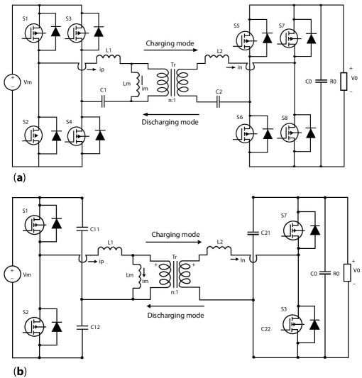
Figure 13.1 (a) Bidirectional FBCLLC resonant converter [9] (b) Bidirectional HBCLLC resonant converter [9].
The auxiliary half-bridge contains two power MOSFETs and two capacitors. The input and output sides are linked by the transformer T. Here, the transformer turns ratio is 1: n.
The maximum conversion efficiency is more than 95%. With increasing output power, the efficiency increases until the efficiency reach its maximum value.
An interleaved bidirectional DC–DC isolated converter as shown in Figure 13.4. Switching losses are fairly decreased due to soft switching of semi-conductor switches that is ZVS of secondary switches and ZCS of primary switches. The converter operates in the reverse mode as a conventional full-bridge DC–DC voltage-fed converter by a load side filter. To attain ZCS of the low voltage side and ZVS of the high voltage side, normal phase modification modulation can be hired [11]. The efficiency comparison presented in Figure 13.5.
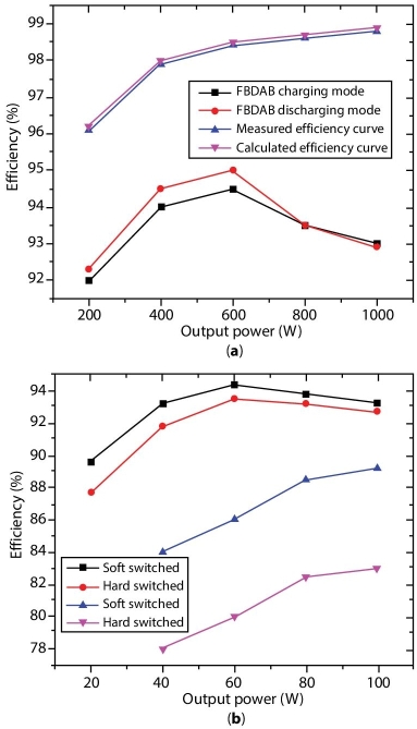
Figure 13.2 (a) Calculated and measured efficiency curves used for the DC–DC isolated DC–DC GaN converter and FBDAB converter [9, 13]. (b) Comparison of soft switched converter versus hard switched converter [5, 16].
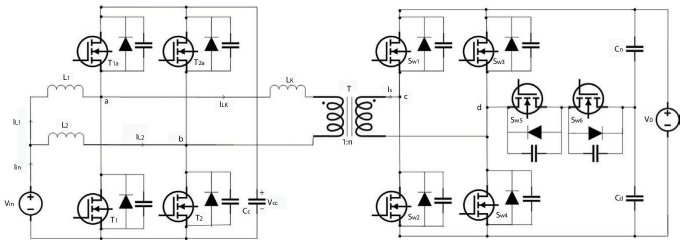
Figure 13.3 DAB DC–DC converter [10].
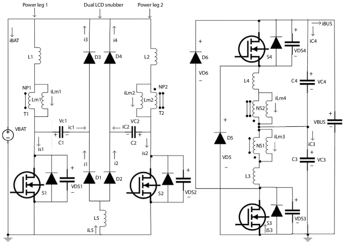
Figure 13.4 Interleaved bidirectional DC–DC Isolated converter circuit.
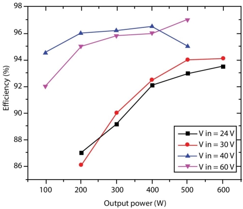
Figure 13.5 Graph between Efficiency versus output power [10, 23].
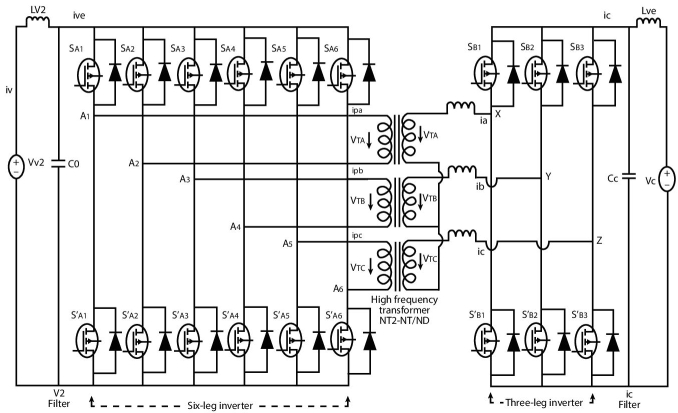
Figure 13.6 Three phase DC-DC converter.
The DC/DC bidirectional Three phase converter technique combines the six-leg converter and three-phase DAB converters. The topology can increase the power capability and withstand high currents of the DAB converter, preserving related modulation technique without changing its main features. Compared to conventional current fed ![]() bidirectional DC-DC converters this converter has additional switches (Figure 13.6).
bidirectional DC-DC converters this converter has additional switches (Figure 13.6).
13.3 Three-Phase DC–DC Converter
A three-phase DC–DC converter used as bidirectional converter in between the source and battery of the vehicle. The proposed ![]() DC–DC bidirectional converter with six leg inverter have more current capability compared toÂ
DC–DC bidirectional converter with six leg inverter have more current capability compared to ![]() DAB converter. This converter is relevant for EV charging.
DAB converter. This converter is relevant for EV charging.
13.4 Conclusion
The DC–DC isolated power converters extensively used in EV and dc microgrids. The CLLC converters are slightly better than the DAB converters for comprehensive bidirectional EV charge systems. The voltage stress and di/dt value of the isolated three-port DC–DC bidirectional converter main switch have been decreased compared to the equivalent hard-switched converter. The converter peak efficiency is 94.5%. The LLC can achieve an efficiency of 98.39% undercharging condition and 97.80% in discharged condition. The GaN converter achieved 98.8% efficiency at 50% of the full load.
References
- 1. Li, R. and Shi, F., Control and Optimization of Residential Photovoltaic Power Generation System With High Efficiency Isolated Bidirectional DC– DC Converter. IEEE Access, 7, 116107–116122, 2019.
- 2. Wang, L., Zhu, Q., Yu, W., Huang, A.Q., A medium-voltage medium-frequency isolated DC–DC converter based on 15-kV SiC MOSFETs. IEEE J. Emerg. Sel. Topics Power Electron., 5, 1, 100–109, 2016.
- 3. Emrani, A., Adib, E., Farzanehfard, H., Single-switch soft-switched isolated DC–DC converter. IEEE Trans. Power Electronics, 27, 4, 1952–1957, 2011.
- 4. Modepalli, K., Ali, M., Tao, L., Leila, P., Three-phase current-fed isolated DC–DC converter with zero-current switching. IEEE Trans. Ind. Appl., 53, 1, 242–250, 2016.
- 5. Zeng, J., Qiao, W., Qu, L., An isolated three-port bidirectional DC–DC converter for photovoltaic systems with energy storage. IEEE Trans. Ind. Appl., 51, 4, 3493–3503, 2015.
- 6. Kolluri, S. and Lakshmi Narasamma, N., A new isolated auxiliary current pump module for load transient mitigation of isolated/nonisolated step-up/ step-down DC–DC converter. IEEE T. Power Electron., 30, 10, 5991–6000, 2015.
- 7. Jou, H.-L., Huang, J.-J., Wu, J.-C., Wu, K.-D., Novel isolated multilevel DC– DC power converter. IEEE T. Power Electron., 31, 4, 2690–2694, 2015.
- 8. Xing, Z., Ruan, X., You, H., Yang, X., Yao, D., Yuan, C., Soft-switching operation of isolated modular DC/DC converters for application in HVDC grids. IEEE T. Power Electron., 31, 4, 2753–2766, 2015.
- 9. He, P. and Khaligh, A., Comprehensive analyses and comparison of 1 kW isolated DC–DC converters for bidirectional EV charging systems. IEEE T. Trans. Elect., 3, 1, 147–156, 2016.
- 10. Sha, D., Xu, Y., Zhang, J., Yan, Y., Current-fed hybrid dual active bridge DC– DC converter for a fuel cell power conditioning system with reduced input current ripple. IEEE T. Ind. Electron., 64, 8, 6628–6638, 2017.
- 11. Xuewei, P. and Rathore, A.K., Novel bidirectional snubberless naturally commutated soft-switching current-fed full-bridge isolated DC/DC converter for fuel cell vehicles. IEEE T. Ind. Electron., 61, 5, 2307–2315, 2013.
- 12. Waltrich, G., Hendrix, M.A.M., Duarte, J.L., Three-phase bidirectional DC/ DC converter with six inverter legs in parallel for EV applications. IEEE T. Ind. Electron., 63, 3, 1372–1384, 2015.
- 13. Ramachandran, R. and Nymand, M., Experimental demonstration of a 98.8% efficient isolated DC–DC GaN converter. IEEE T. Ind. Electron., 64, 11, 9104–9113, 2016.
- 14. Chen, Y., Zhao, S., Li, Z., Wei, X., Kang, Y., Modeling and control of the isolated DC–DC modular multilevel converter for electric ship medium voltage direct current power system. IEEE J. Emerg. Select. Topics Power Electron., 5, 1, 124–139, 2016.
- 15. Cong, L. and Lee, H., A 1–2-MHz 150–400-V GaN-based isolated DC–DC bus converter with monolithic slope-sensing ZVS detection. IEEE J. Solid-State Circuits, 53, 12, 3434–3445, 2018.
- 16. Yeşilyurt, H. and Bodur, H., New active snubber cell for high power isolated PWM DC–DC converters. IET Circ. Device. Syst., 13, 6, 822–829, 2019.
- 17. Liu, C., Mandal, D., Yao, Z., Sun, M., Todsen, J., Johnson, B., Kiaei, S., Bakkaloglu, B. A 50-V Isolation, 100-MHz, 50-mW Single-Chip Junction Isolated DC-DC Converter With Self-Tuned Maximum Power Transfer Frequency. IEEE Trans. Circuits Systems II: Express Briefs, 66, 6, 1003–1007, 2018.
- 18. Huang, R. and Mazumder, S.K., A soft-switching scheme for an isolated dc/ dc converter with pulsating dc output for a three-phase high-frequency-link PWM converter. IEEE T. Power Electron., 24, 10, 2276–2288, 2009.
- 19. Kan, J., Wu, Y., Tang, Y., Zhang, B., Zhang, Z., Dual active full-bridge bidirectional converter for V2G charger based on high-frequency AC buck-boost control strategy, in: 2016 IEEE Transportation Electrification Conference and Expo, Asia-Pacific (ITEC Asia-Pacific), Busan, Korea, pp. 046–050, IEEE, 2016.
- 20. Xuewei, P. and Rathore, A.K., Comparison of bi-directional voltage-fed and current-fed dual active bridge isolated dc/dc converters low voltage high current applications, in: 2014 IEEE 23rd International Symposium on Industrial Electronics (ISIE), Istanbul, Turkey, pp. 2566–2571, IEEE, 2014.
- 21. Sha, D. and Xu, G., High-Frequency Isolated Bidirectional Dual Active Bridge DC–DC Converters with Wide Voltage Gain., Springer, United States, 2018.
- 22. Zhan, Y., Guo, Y., Zhu, J., Li, L., Input current ripple reduction and high efficiency for PEM fuel cell power conditioning system, in: In 2017 20th International Conference on Electrical Machines and Systems (ICEMS), Sydney, Australia, pp. 1–6, IEEE, 2017.
- 23. Wu, H., Mu, T., Ge, H., Xing, Y., Full-range soft-switching-isolated buck-boost converters with integrated interleaved boost converter and phase-shifted control. IEEE T. Power Electron., 31, 2, 987–999, 2015.
Note
- * Corresponding author: [email protected]