Chapter 8
Hatching and Gradients
The term hatching refers to filling bounded areas with solids, patterns, and/or gradients. You create hatching in the AutoCAD® program to indicate transitions between materials and to improve the readability of drawings in general. Hatching with solid fill, patterns, and/or tonal gradients can transform staid line drawings into attractive illustrations. This chapter covers the basics of hatching so that you can use it in your own drawings.
- Specifying hatch areas
- Associating hatches with boundaries
- Hatching with patterns
- Hatching with gradients
Specifying Hatch Areas
Every hatch area is defined by a boundary containing the solid fill, pattern, or gradient. The boundary can be determined either by picking a point on the drawing canvas or by selecting an object or set of objects.
Picking Points to Determine Boundaries
When a boundary is picked, AutoCAD uses a raycasting algorithm to determine the precise extents of the area bounded by the objects on screen. In the following steps, you will pick points to determine the boundaries of multiple hatch objects:
1. Go to the book’s web page at
www.sybex.com/go/autocad2013essentials, browse to Chapter 8, get the file
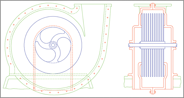
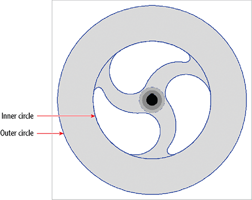
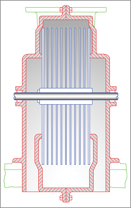
Ch8-A.dwg, and open it. The drawing is based on a 100-year-old patent for fluid propulsion (CA 135174) by Nikola Tesla (see
Figure 8-1). Tesla is best known for inventing the alternating electrical current that powers the modern age.
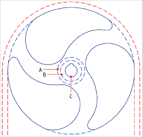
2. Zoom into the center of the rotor in the drawing on the left.
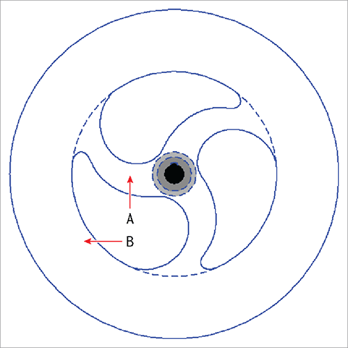
3. Click the Hatch tool in the Draw panel on the ribbon’s Home tab. Click point A in
Figure 8-2.
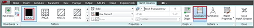
4. A temporary contextual tab called Hatch Creation appears on the ribbon. This tab will remain active while you configure the hatch object that you are creating. Click Solid in the Pattern panel, and turn off Associative mode if it is on by clicking its button in the Options panel (see
Figure 8-3). (You’ll learn about associative hatches in the next section.)
5. Expand the Options panel, open the Island Detection menu, and select Outer Island Detection. The thumbnails indicate different ways of treating nested boundaries, called islands. In this case, you want only the outer island filled with a solid hatch.
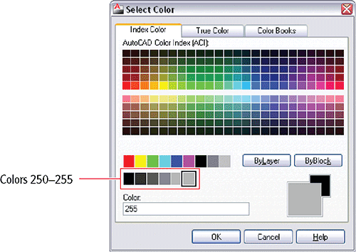
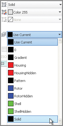
6. Open the Hatch Color drop-down in the Properties panel, and choose Select Colors at the bottom of the list of standard colors. Choose color 255 from the Select Color dialog box and click OK (see
Figure 8-4).
You can override a hatch object’s default color, transparency, and layer assignment on the Hatch Creation tab’s Properties panel.
7. Expand the Properties panel, open the Hatch Layer Override drop-down, and select the Solid layer (see
Figure 8-5).
8. Click the Close Hatch Creation icon in the Close panel at the extreme right edge of the ribbon’s Hatch Editor tab. The outer island is filled with a solid hatch object, and the
HATCH command ends.
9. Type
H (for Hatch), and press Enter. Click point B in
Figure 8-2.
All the settings and overrides in the Hatch Creation tab are “sticky,” meaning that they remain the same the next time you create a hatch object.
10. Open the Hatch Color drop-down in the Properties panel, and choose Select Colors at the bottom of the list of standard colors. Choose color 253 from the Select Color dialog box and click OK.
11. Click the Close Hatch Creation icon in the Close panel.
12. Press the spacebar to repeat the last command. Click point C in
Figure 8-2.
13. Open the Hatch Color drop-down in the Properties panel, and choose Select Colors at the bottom of the list of standard colors. Choose color 250 from the Select Color dialog box and click OK.
14. Click the Close Hatch Creation icon in the Close panel. The Hatch Editor tab disappears.
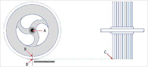
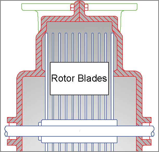
15. Click the Isolate tool on the Layers panel of the ribbon’s Home tab, drag a crossing selection over the hub, and include the selection of at least one of the dashed blue lines defining the edge of a spoke. Press Enter, and all the other layers are hidden, leaving the entire rotor.
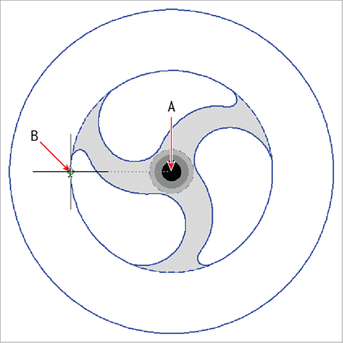
16. Click the Hatch tool on the Draw panel, and then click point A in
Figure 8-6.
Use the BOUNDARY command to create a polyline or region object from a picked point. BOUNDARY uses the same raycasting algorithm used by the HATCH command.
17. Open the Hatch Color drop-down in the Properties panel, and choose Select Colors at the bottom of the list of standard colors. Choose color 255 from the Select Color dialog box and click OK.
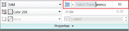
18. Drag the Hatch Transparency slider to the right until the value is approximately 50 (see
Figure 8-7).
19. Toggle on the Show/Hide Transparency button on the status bar. The hatch pattern you just created appears partially transparent.
20. Type
H (for Hatch), and press Enter. Click point B in
Figure 8-6. The command prompt reads:
Analyzing the selected data...
AutoCAD can’t find this particular area; press Esc before the program crashes.
The raycasting algorithm has a tendency to crash when analyzing complex areas, such as arcs, splines, and a circle forming the boundary of the outer portion of the rotor.
21. Save your work as Ch8-B.dwg.
Selecting Objects to Define Boundaries
In complex drawings, picking points to determine boundaries sometimes doesn’t work. Fortunately, you can always define boundaries successfully using closed objects. In the following steps, you will select two closed objects to define a hatch boundary.
1. If the file is not already open from performing the previous step, go to the book’s web page, browse to Chapter 8, get the file Ch8-B.dwg, and open it.
2. In the previous section, the raycasting algorithm probably had trouble with the inner part of the rotor where the arcs and splines meet. To simplify the boundary, you will draw a circle. Click the Circle tool on the Draw panel.
Don’t worry about which layer the circle you are drawing is located; you will delete the circle later.
3. Shift+right-click, and choose Node from the context menu. Click point A, shown in
Figure 8-8, as the center point. Type
QUA (for Quadrant), and press Enter. Click point B in
Figure 8-8 to set the inner circle’s radius. The
CIRCLE command ends.
4. Type
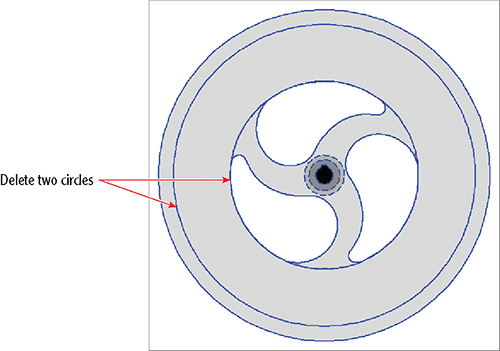
H (for Hatch), and press Enter. Click the Select Boundary Objects tool in the Boundaries panel of the ribbon’s Hatch Editor tab. Select the circle making up the inner circle of the rotor, and then select the single outer circle. Select Solid in the Pattern panel and press Enter. The hatch appears correctly (see
Figure 8-9); click the Close Hatch Editor icon in the Close panel at the extreme right edge of the Hatch Editor tab.
5. Click the Erase tool on the Home tab’s Modify panel. Select the inner circle you drew in step 3 and press Enter. The dashed arcs are again visible after using the
REGEN command to regenerate the display of objects on the screen.
6. Save your work as Ch8-C.dwg.
Associating Hatches with Boundaries
When hatches are associated with their boundary objects, the boundary objects themselves define the extents of the hatch fill, pattern, or gradient. Altering the shape of any of the boundary objects necessarily changes the extents of an associated hatch object. For example, the rotor needs to have a larger diameter and, by associating the hatch with the outer circle, you will be able to get the hatch to expand to fill the larger rotor simply by changing the diameter of the circle.
When hatches are not associated with their boundary objects, altering the boundary objects does not change the shape of the hatch.
In the following steps, you will re-create the boundary objects from the last hatch pattern created in the previous section. Then you will alter the shape of one of the boundary objects to change the extents of the solid hatch.
1. If the file is not already open from performing the previous step, go to the book’s web page, browse to Chapter 8, get the file Ch8-C.dwg, and open it.
2. Click the outer portion of the rotor to select the hatch object; the Hatch Editor tab appears on the ribbon.
3. Click the Recreate Boundary tool on the Boundaries panel. The command prompt reads:
Enter type of boundary object [Region Polyline] <Polyline>:
Press Enter to accept Polyline as the default option. Now the prompt says:
Associate hatch with new boundary? [Yes No] <Y>:
Press Enter again to accept the default, Yes. Two new circles are created and associated with the hatch.
4. Click the Close Hatch Editor icon in the Close panel.
5. Toggle on Object Snap on the status bar. Right-click this toggle button, and turn on Center, Quadrant, and Endpoint running object snap modes in the context menu if they are not already on.
6. Toggle on Ortho mode on the status bar.
7. Toggle on Object Snap Tracking on the status bar.
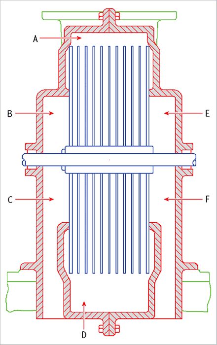
8. Click the Scale tool on the Modify panel, select the rotor’s outer circle, and press Enter. Select the center of the rotor (point A in
Figure 8-10) as the base point. The command prompt reads:
Specify scale factor or [Copy Reference]:
Type
R (for Reference), and press Enter. Pick the reference length by clicking points A and B in
Figure 8-10.
9. Hover the cursor over point C, as shown in
Figure 8-10. Then bring the cursor back toward point D. When the tracking X appears on the drawing canvas, click point D. When the
SCALE command ends, the rotor matches its depiction in the drawing on the right and the solid associative hatch fills the new boundary.
10. Click the outer portion of the rotor to select the hatch object; the Hatch Editor tab appears on the ribbon.
11. Convert the object into a nonassociative hatch by clicking to toggle off the Associative button in the Options panel, and then click the Close Hatch Editor icon.
12. Click the Erase tool on the Modify panel, select the two re-created boundaries as shown in
Figure 8-11, and press Enter.
13. Click the Unisolate tool on the Layers panel.
14. Save your work as Ch8-D.dwg.
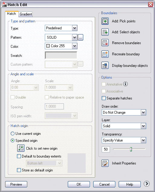
Accessing the Hatch Edit Dialog Box
You can access all the hatching tools that you see on the ribbon in a dialog box interface by selecting a hatch object using the HATCHEDIT command. You’ll see this dialog box when using the HATCH command if you are using a workspace that doesn’t have the ribbon (such as AutoCAD Classic).
Hatching with Patterns
Hatch patterns are repeating arrangements of lines and/or dots used to identify a material or a cutting plane, or to highlight an area visually. You’ll learn how to specify pattern properties, separate hatch areas, and set the origin point of the pattern.
Specifying Properties
Hatch patterns have a few additional properties as compared to solid hatch objects. In the following steps, you will select a pattern, set its scale, and adjust the pattern angle.
1. If the file is not already open from performing the previous step, go to the book’s web page, browse to Chapter 8, get the file Ch8-D.dwg, and open it.
2. Pan over to the drawing on the right.
3. Click the Hatch tool on the Draw panel.
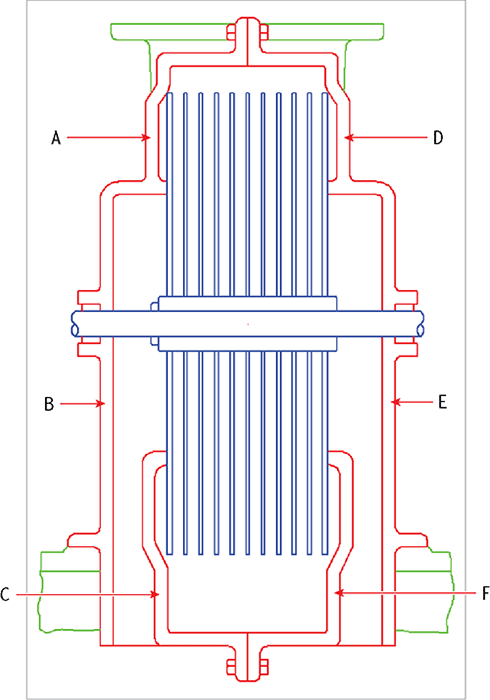
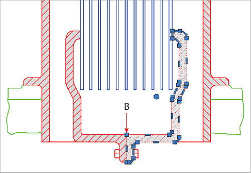
4. Click points A through F inside the red housing, as shown in
Figure 8-12. A solid hatch appears within the red boundaries.
Increase Gap Tolerance in the Options panel (try a value of 0.1) if AutoCAD says a boundary is not closed.
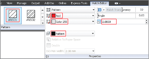
5. Select the pattern called ANSI31 in the Pattern panel if it is not already selected. Select Red in the Color drop-down in the Properties panel. Select Color 255 in the Background Color drop-down. Repeatedly click Scale’s up arrow to increase the value to 2.000. Expand the Properties panel, and select Pattern from the Hatch Layer Override drop-down (see
Figure 8-13).
6. Click Close Hatch Editor in the Close panel.
7. Save your work as Ch8-E.dwg.
Separating Hatch Areas
When you picked points within multiple boundaries in the previous section, it formed a single hatch object. The properties you specified were assigned to this object. However, at this point we want to rotate the cross-sectional pattern 90º on the right side to illustrate better the separate pieces of metal that are bolted together. In the following steps, you will separate the multiple bounded areas of a single object into individual hatch objects and then rotate patterns on half of them:
1. If the file is not already open from performing the previous step, go to the book’s web page, browse to Chapter 8, get the file Ch8-E.dwg, and open it.
2. Select the hatch object you created in the previous section.
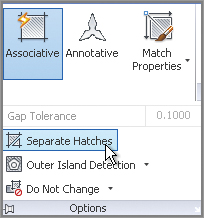
3. Expand the Options panel, and click Separate Hatches (see
Figure 8-14).
4. Click Close Hatch Editor in the Close panel.
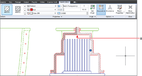
5. Select the upper-right hatch pattern, type
90 in the Angle text box, and press the Tab key. Click the Set Origin button, and then click point A shown in
Figure 8-15. Press Esc to exit the ribbon’s Hatch Editor tab.
Exploding hatch patterns removes their associativity (if any). Exploding them again converts the hatch pattern into its constituent lines; background color fill is lost in the process.
6. Select the hatch pattern on the left side, click the Set Origin button, click point A as shown in
Figure 8-15, and press Esc. The outer patterns on left and right both meet symmetrically at point A.
7. Select the pattern on the lower right, click the Match Properties tool in the Options panel, and select the upper-right pattern. Press Esc to deselect; the lower pattern matches the upper pattern’s angle.
8. Select the inner pattern on the right. Click the Match Properties tool in the Options panel, and select the lower-right pattern.
9. Click the Set Origin button, and click point B in
Figure 8-16. Press Esc to deselect.
10. Select the inner pattern on the left. Click the Set Origin button, and click point B in
Figure 8-16. Press Esc to deselect. The inner patterns on the left and right both meet symmetrically at point B.
Figure 8-17 shows the result.
11. Save your work as Ch8-F.dwg.
Hatching with Gradients
In addition to hatching with solid fill and line patterns, you can hatch with one- and two-color gradients to vary tonality in a smooth fashion. Gradients can subtly hint at an extra dimension that helps make drawings more readable. In the following steps, you will create gradient hatches that give depth to metal parts in the drawings.
1. If the file is not already open from performing the previous step, go to the book’s web page, browse to Chapter 8, get the file
Ch8-F.dwg, and open it.
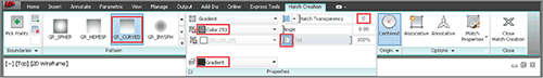
2. Open the flyout next to the Hatch tool on the Draw panel, and select Gradient from the menu. Click points A through F shown in
Figure 8-18.
3. Scroll down in the Pattern panel, and select the GR_CURVED gradient. Select Color 253 in the Gradient Color 1 drop-down. Click the Gradient Tint And Shade button (if it is not already highlighted in blue) to create a one-color gradient. Drag the Hatch Transparency slider all the way to the left until its value reads 0. Expand the Properties panel and select Gradient in the Hatch Layer Override drop-down (see
Figure 8-19). Click the Close Hatch Creation icon at the right edge of the ribbon.
Click the Gradient Tint And Shade button to toggle one- or two-color gradients. You can select both colors in two-color gradients whereas one-color gradients fade to white.
4. Zoom in on the rotor shaft.
5. Type
GRADIENT, and press Enter. Click a point in the center of the shaft to determine the boundary for a new gradient hatch. Select the GR_CYLIN pattern, set Angle to 90, and select Color 250 in the Gradient Color 1 drop-down. Click the Close Hatch Creation icon.
Figure 8-20 shows the result.
6. Objects typically overlap other objects that were drawn earlier. Type HATCHTOBACK, and press Enter. All hatch objects (solid fills, patterns, and/or gradients) are sent to the back of the draw order stack so that they don’t overlap any of the other objects in the drawing.
Use the DRAWORDER command to change the display behavior of individual overlapping objects.
7. Your drawing should now resemble Ch8-G.dwg, which is available for download at the book’s web page.
The Essentials and Beyond
In this chapter, you have learned how to create hatch objects that are filled with solid color, line patterns, and/or gradients. You now have the tools to improve the readability of your drawings by graphically indicating transitions between materials and section cutting planes, and by adding depth to parts with variable shading.
Additional Exercise
Explore the WIPEOUT command on your own. Think of wipeouts as solid hatches that completely obscure what they cover with the current canvas background color. They can be useful in complex drawings when you want to wipe out areas to make room for notes. Try creating a wipeout object that obscures a portion of the upper rotor blades in the cross-sectional drawing on the right of Ch8-G.dwg.