Chapter 11
Dimensioning
Dimensioning is the art of annotating drawings with precise numerical measurements. The process is generally straightforward in the AutoCAD® program because everything is typically drawn in real-world scale. Dimensions will automatically display the correct measurements as long as the geometric objects to which they refer are drawn to actual size.
In this chapter, you’ll learn the mechanics of dimensioning in model space. Dimensioning in paper space and in viewports is covered in Chapter 13, “Working with Layouts.”
- Styling dimensions
- Adding dimensions
- Editing dimensions
Styling Dimensions
The appearance of dimensions (the size of text and arrows, the length of extension lines, and so on) is controlled by dimension styles. Every drawing comes with a Standard dimension style, which of course is the current style as there is only one by default. When you have more than one dimension style, you must choose which one is current. New dimension objects are assigned the current dimension style in much the same way that objects and layers or text and text styles work.
You can customize dimension styles and even create substyles to control the way different types of dimensions appear according to your personal preferences, or to adhere to a corporate or industry standard established for dimensions. For example, if you want to use architectural tick marks rather than arrowheads for linear and aligned dimensions but want to use arrowheads for radius, diameter, and angular dimensions, these preferences can be encoded in a dimension style and a series of substyles.
In the following steps, you will modify the Standard dimension style and create a few substyles for specific types of dimensions in preparation for adding dimension objects in the next section.
The sample files in this chapter use generic units, so they can be used by both Imperial and metric users.
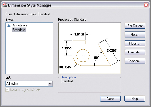
2. Select the Home tab on the ribbon if it is not already selected. Expand the Annotation panel, and click the Dimension Style tool (see
Figure 11-2).
3. As you can see in the Dimension Style Manager, every drawing has Standard and Annotative dimension styles by default (see
Figure 11-3). The Standard style is selected by default. Click the Modify button to alter the Standard style.
You will learn about Annotative styles in Chapter 13.
Styling Dimensions in Multiple Drawings
Modifying dimension styles in a particular drawing in no way affects the dimensions or styles in other drawings. If you want to use the same dimension styles in future drawings, customize the dimension styles in your drawing template.
4. Select the Primary Units tab in the Modify Dimension Style: Standard dialog box. Set Precision to 0.000, and select Trailing in the Zero Suppression section (see
Figure 11-4). If you are in a country that uses a comma instead of a period as a decimal separator, select “,” (Comma) in the Decimal Separator drop-down menu.
5. Select the Symbols And Arrows tab. In the Arrowheads section, choose Open 30 from the First drop-down (see
Figure 11-5). The Second drop-down automatically matches the first by default as it now says Open 30.
6. Select the Lines tab. Double-click the Offset From Origin value to select it, type
0.125, and press Tab (see
Figure 11-6). Observe in the preview image how the distance between the object and its extension lines increases. Click OK and Close to save the modifications you’ve made to the Standard style.
Understanding Dimension Styles
Changing a dimension style automatically updates all existing dimension objects in the current drawing that have that style assigned.
7. Type
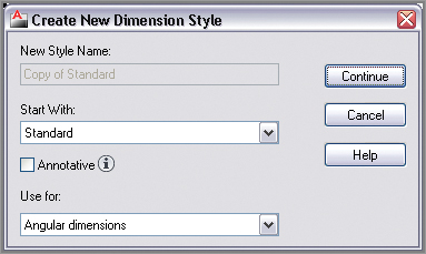
D (for Dimension Style), and press Enter. The Dimension Style Manager reappears. Click the New button to open the Create New Dimension Style dialog box. Verify that Start With is set to Standard. Choose Angular Dimensions from the Use For drop-down (see
Figure 11-7). Click Continue.
8. The New Dimension Style: Standard: Angular dialog box appears. Select the Symbols And Arrows tab. Change the First arrowhead drop-down to Closed Filled. The Second arrowhead automatically changes to Closed Filled as well (see
Figure 11-8). The preview image reveals how the angular dimension will appear. Click OK.
9. Click the New button again in the Dimension Style Manager. Select Radius Dimensions in the Use For drop-down and click Continue. Select Closed Filled in the Second arrowhead on the Symbols And Arrows tab. The preview image again reveals what a radial dimension will look like governed by this substyle; click OK.
10. Select Standard in the styles list in the left pane of the Dimension Style Manager. The preview image now shows the cumulative effect of the style and its substyles: open arrowheads for linear and aligned dimensions and closed filled arrowheads for angular and radial dimensions.
Figure 11-9 lists these types. Click Close.
11. Save your work as Ch11-B.dwg. Dimension styles are saved within the drawing.
Linear dimensions can either be horizontal or vertical. Aligned dimensions measure linear distances at angles other than horizontal or vertical.
Adding Dimensions
In technical drawings, dimensions are typically measurements for which the designer may be legally responsible. So while it is essential to know how to add specific dimensions to a drawing, it is also useful for your own information to use inquiry commands that measure linear objects (MEASUREGEOM or DIST) or find areas (AREA) without making specific annotations in the drawing (thus avoiding potential liability). You will explore how to do this in the following section. In addition, you will add a variety of dimension objects that show specific measurements on the drawing. The section ends with a discussion on how to add a multileader, which is text pointing to a specific feature with an arrow, to a drawing.
Using Inquiry Commands
Use inquiry commands when you want to find out (but not document) how long, what angle, what name, or what area a specific feature has without annotating the drawing with this information. In the following steps, you’ll explore inquiry commands to get these specific types of information from a drawing:
1. If the file is not already open, go to the book’s web page, browse to Chapter 11, get the file Ch11-B.dwg, and open it.
2. Toggle on Object Snap mode on the status bar if it is not already on. Right-click the Object Snap button, and turn on Endpoint and Intersection running object snap modes.
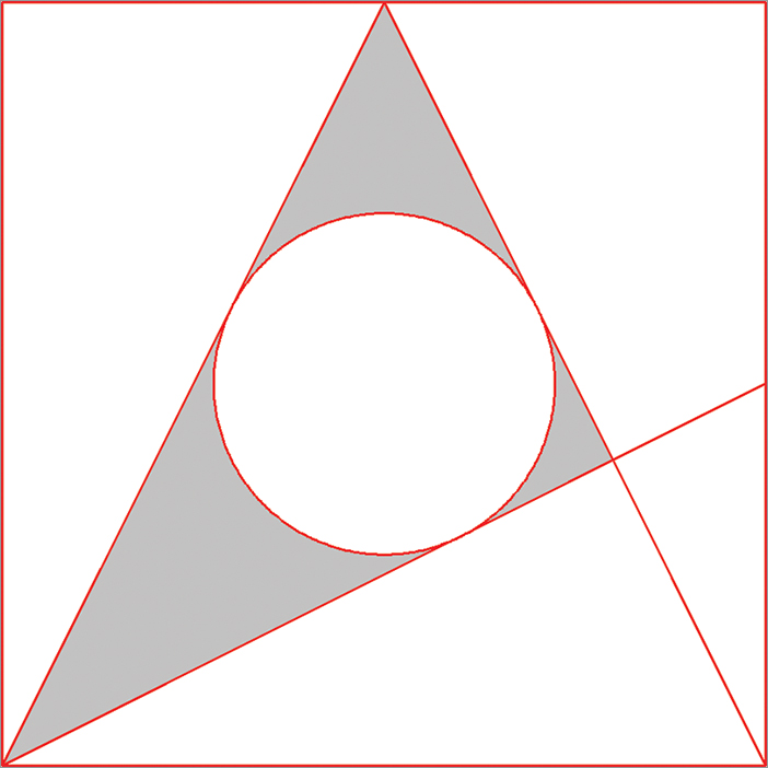
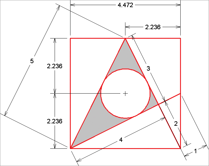
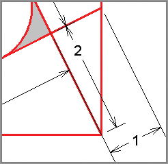
3. Toggle on Dynamic Input on the status bar. Click the Distance tool in the Utilities panel of the Home tab on the ribbon. Click points A and B, as shown in
Figure 11-10. The distance 5.000 is shown on screen, and the command prompt reads:
Distance = 5.000, Angle in XY Plane = 26.565,
Angle from XY Plane = 0.000 Delta X = 4.472,
Delta Y = 2.236, Delta Z = 0.000
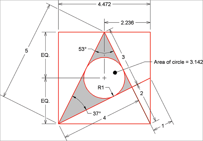
4. Open the Measure menu in the Utilities panel, select the Radius tool, and select the circle. The command prompt reads:
Radius = 1.000
Diameter = 2.000
5. Type
A (for Angle), and press Enter. Select lines A and B, as shown in
Figure 11-11. The command prompt now gives the value:
Angle = 36.87°
The number of decimal places shown in the inquiry commands is controlled by the Precision drop-downs in the Drawing Units dialog box (accessed with the UNITS command).
6. Type
AR (for area), and press Enter. The command prompt reads:
Specify first corner point or
[Object Add area Subtract area eXit]
<Object>:
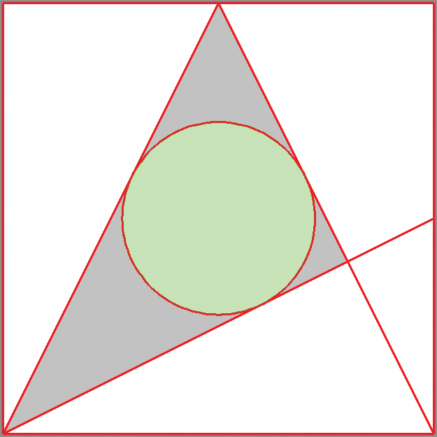
7. Press Enter to accept the default Object option, and select the circle. The command prompt gives the values:
Area = 3.142, Circumference = 6.283
8. The area within the circle turns green to give you a visual indication of which area and circumference are measured.
Figure 11-12 shows the circle’s area of π and circumference of 2 π. Press Esc and the
MEASUREGEOM command ends.
Adding Dimension Objects
In the following steps, you’ll add dimension objects one at a time using a variety of specialized tools to produce dimensions that are linear, aligned, angular, radial, and so on.
1. If the file is not already open from performing the previous step, go to the book’s web page, browse to Chapter 11, get the file Ch11-B.dwg, and open it.
2. Toggle on Object Snap mode on the status bar if it is not already on. Right-click this button, and turn on Endpoint and Intersection running object snap modes if necessary.
3. Click the Linear dimension tool on the Annotation panel. Click points A and B to specify the first and second extension line origin points, as shown in
Figure 11-13. Click point C to specify the dimension line location.
Dimension objects are typically associated with the geometry to which they refer so that, when you modify the geometry, the dimensions automatically update with new measurements.
4. Press the spacebar to repeat the last command. The command prompt reads:
Specify first extension line origin or <select object>:
Press Enter to accept the default option (Select Object). Click the top red line, and then click point A, as shown in
Figure 11-14.
5. Type
DIMCENTER (for Dimension Center Mark), and press Enter. Select the circle, and a small crosshair symbol appears at the center of the circle.
6. Type
DIMLIN (the alias for the
DIMLINEAR command), and press Enter. Click points A, B, and C, as shown in
Figure 11-15.
7. Type
DIMCONTINUE (for Dimension Continue), and press Enter. Click point A, as shown in
Figure 11-10, to add another linear dimension below the previous one. Press Esc to end the command.
Using DIMCONTINUE to add adjacent linear dimensions is more efficient than using DIMLINEAR.
8. Open the dimension menu in the Annotation panel, and select the Aligned tool. Click points A, B, and C, as shown in
Figure 11-16.
9. Add the four additional aligned dimensions shown in
Figure 11-17 measuring 1, 2, 3, and 4 units.
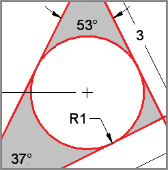
10. Open the dimension menu in the Annotation panel, and select the Angular tool. Select lines 1 and 2, as shown in
Figure 11-18, and then click point A. Press the spacebar to repeat the
DIMANGULAR command, select lines 2 and 3, and then click point B.
11. Open the dimension menu in the Annotation panel, and select the Radius tool. Select the circle, and then click a point inside the circle to locate the radius value (see
Figure 11-19).
12. Save your work as Ch11-C.dwg.
Adding and Styling Multileaders
A multileader is text with a line tipped by an arrowhead that leads the eye to specific geometric features. Multileader styles control the appearance of leader objects in much the same way that dimension styles control the appearance of dimensions. In the following steps, you will add a leader object and then configure the multileader style.
1. If the file is not already open, browse to Chapter 11, get the file Ch11-C.dwg, and open it.
2. Select the Leader tool in the Annotation panel. Click points A and B, type
Area of circle = 3.142 (as shown in
Figure 11-20), and then press Ctrl+Enter. You have to use Ctrl in addition to Enter to end the command because Enter by itself advances to the next line.
3. Expand the Annotation panel, and select the Multileader Style button. Click the Modify button in the Multileader Style Manager dialog box that appears.
4. Choose Dot from the Symbol drop-down in the Arrowhead section on the Leader Format tab of the Modify Multileader Style: Standard dialog box (see
Figure 11-21). Click OK and Close, and the leader object automatically has a dot on its end.
5. Save your work as Ch11-D.dwg.
Editing Dimensions
Dimensions have grips that allow you to reposition extension lines, the dimension line, and dimension text independently of one another. In the following steps, you will edit the length and location of extension and dimension lines directly with grips, adjust a dimension style to affect the appearance of dimension objects, and use a few specialized dimension-editing commands:
1. If the file is not already open, browse to Chapter 11, get the file Ch11-D.dwg, and open it.
2. Toggle on Object Snap mode on the status bar if it is not already on. Right-click the Object Snap button, and turn on Endpoint and Intersection running object snap modes.
3. Click the horizontal linear dimension with a value of 2.236 to select it. Click the lower-left grip to adjust the length of this extension line. Snap the grip to point A, as shown in
Figure 11-22. Press Esc to deselect.
4. Type D (alias for the DIMSTYLE command), and press Enter. Select the Angular substyle in the Dimension Style Manager that appears, and click the Modify button.
5. Select the Fit tab in the Modify Dimension Style: Standard: Angular dialog box. Select the Text radio button in the Fit Options section (see
Figure 11-23). Click OK and Close to close all open dialog boxes. The angular values appear outside the lines being measured.
6. Type
DIMEDIT (for Dimension Edit), and press Enter. The command prompt reads:
Enter type of dimension editing
[Home New Rotate Oblique] <Home>:
7. Type N (for New), and press Enter. A text-editing window appears below the last text you entered. Delete the zero.
8. Type
EQ (for Equal), and then press Ctrl+Enter to end text entry mode. Select both vertical linear dimensions having values of 2.236, and press Enter.
Figure 11-24 shows the result.
9. Type
DIMTEDIT (for Dimension Text Edit), and press Enter. Select the aligned dimension with a value of 2 and press Enter. The command prompt reads:
Specify new location for dimension text or
[Left Right Center Home Angle]:
10. Type
L (for Left), and press Enter. The dimension text is now left-justified in relation to the dimension line, so the 2 is more easily read within the whitespace left within the red lines (see
Figure 11-25).
11. Select the ribbon’s Annotate tab, and click the Break tool on the Dimensions panel. The command prompt reads:
Select dimension to add/remove break or [Multiple]:
12. Type
M (for Multiple), and press Enter. Select the dimensions with values of 2.236, 3, and 5 and press Enter. The command prompt reads:
Select object to break dimensions or [Auto Remove] <Auto>:
13. Press Enter to accept the default Auto option, and the
DIMBREAK command ends. Breaks are made in the selected dimensions where they cross other objects (see
Figure 11-26).
14. Your drawing should now resemble Ch11-E.dwg, which is available at this book’s web page.
The Essentials and Beyond
In this chapter, you took your first steps in the art of dimensioning. You learned how to adjust dimension styles and create new substyles; how to add linear, aligned, angular, and radial dimension objects; and how to edit dimensions using a variety of techniques.
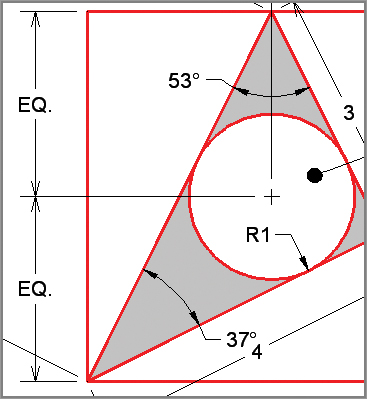
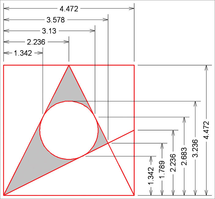
Additional Exercise
Explore the DIMBASELINE command on your own. Baseline dimensions all reference the same base point to eliminate cumulative errors that can crop up due to rounding errors between consecutive adjacent dimensions. Try creating two sets of baseline dimensions that reference the left and bottom edges of the diagram shown here: