
CHAPTER 6
Floors
It’s going to be hard to convince you that floors are easy when an entire chapter is dedicated to this lone aspect of Autodesk® Revit® Architecture software. Well, floors are easy. I’m devoting an entire chapter to the subject because we need to address a lot of aspects of floors.
 Placing a floor slab
- Building a floor by layers
- Splitting the floor materials
- Pitching a floor to a floor drain
- Creating shaft openings
Placing a Floor Slab
Adding a floor to a model is quite simple, but in Revit Architecture, you’re truly modeling the floor. That means you can include the structure and the finish when you create your floor. When you cut a section through the floor, you get an almost perfect representation of your floor system and how it relates to adjacent geometry, such as walls.
Floors, of course, are more than large slabs of concrete. Therefore, in this chapter, you’ll also be introduced to creating materials, and you’ll learn how to pitch these materials to floor drains. You’ll examine how to create sloped slabs as well.
The first area you’ll explore is how to place a slab into your model. It’s as simple as it sounds, but you must follow certain steps, which I’ll outline next. As you’ve learned up to this point, in Revit Architecture you do need to add items the way Revit wants you to add them, or you’ll probably generate errors—or, worse, inaccuracies in your model.
Creating the Slab
To begin, open the file you’ve been using to follow along. If you didn’t complete Chapter 5, “Dimensioning and Annotating,” go to the book’s web page at www.sybex.com/go/revit2017ner. From there you can browse to Chapter 6 and find the file called NER-06.rvt.
The objective of the following procedure is to create a floor slab to be placed into the model:
- In your Project Browser, go to the Level 1 floor plan.
- Zoom into the west wing.
- On the Architecture tab, click the Floor button, as shown in Figure 6.1.
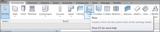
Figure 6.1 The Floor button on the Architecture tab
- Switch to the Properties dialog. Make sure Floors is the current selection, as shown in Figure 6.2.
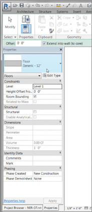
Figure 6.2 Changing the focus of the properties
-
At upper right in the dialog, click the Edit Type button (see Figure 6.3).
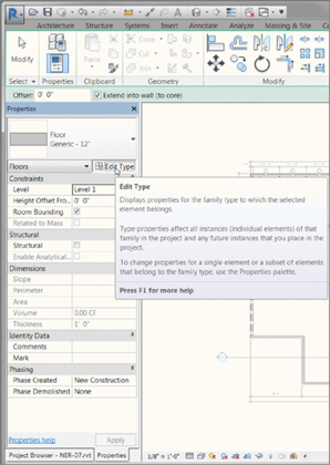
Figure 6.3 Clicking the Edit Type button to begin creating a new floor slab type
You’re now accessing the Type Properties. This means any change you make here will affect every slab of this type in the entire model.
- Click the Rename button, as shown in Figure 6.4.
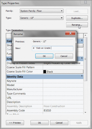
Figure 6.4 Renaming the current floor type. You’ll never have a Generic 12″ (300 mm) floor in your model, so it’s a good idea not to keep this floor type around.
- Call the floor system 6″ Slab on Grade (150 mm Slab on Grade); see Figure 6.4.
- Click OK.
- Change Function to Exterior, as shown in Figure 6.5.
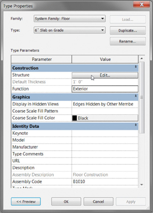
Figure 6.5 Clicking the Edit button to access the structure of the floor
- In the Structure row, click the long Edit button (see Figure 6.5).
You’re now in the Edit Assembly dialog box. This is where you can specify a thickness for your slab. You can add layers of materials here as well.
In the middle of the Edit Assembly dialog box is a large spreadsheet-type field that is divided into rows and columns. The rows are defined by a structural component and include a boundary above and below the structure. It’s the Structure row in which you’re interested here.
- The Structure row is divided into columns. Click in the Material column within the Structure row, as shown in Figure 6.6.
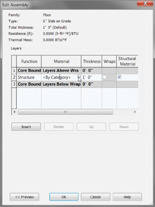
Figure 6.6 By clicking in the Material cell within the Structure row, you can access the Material Browser.
- A small […] button appears when you click in the Material cell. This button indicates that you’ll be given a menu if you click it. Click the […] button to open the Material Browser.
- You can now choose a material from the menu. Scroll down until you arrive at Concrete, Cast-In-Place Gray, and select it.
- Make sure the Graphics tab is current, as shown in Figure 6.7. You can display two different hatches: a sand hatch will be visible for floor plans, and a concrete hatch will be visible for sections (see Figure 6.7). These hatches allow a filling region to designate specific materials graphically.
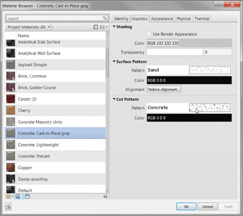
Figure 6.7 The Material Browser
- Make sure Concrete, Cast-In-Place Gray is still selected, and click OK.
-
Back in the Edit Assembly dialog box, the Thickness column is directly to the right of the Material column. Currently the value in the Structure Row is 1′–0″ (300 mm). Click into the cell, and change the value to 6″ (150 mm).
- Click OK.
- Click OK again to get back to the model.
Now that the slab type has been created, you can place an instance into the model. Notice that the Modify | Create Floor Boundary tab is in Sketch Mode. You’ll now proceed to sketch the slab in place.
Sketching the Slab
You’ll have to adjust to the way Revit wants you to proceed with the Create Floor Boundary tab; you’re basically limited to the choices provided in this menu. Not to fear, you should have plenty of choices, but you’ll still need to get a feel for how Revit works.
Here’s what needs to happen: you must draw the perimeter of the slab into the model. This is basically a slab on grade, so you’ll pour the concrete to the inside, finished face of the wall. You won’t worry about a control joint between the wall and the slab at this point.
Picking Walls
The best way to add a slab is to use the Pick Walls button as much as possible (see Figure 6.8). In doing so, you tell Revit that this edge of the slab needs to move if this wall moves. Pick Walls is the default Draw option.
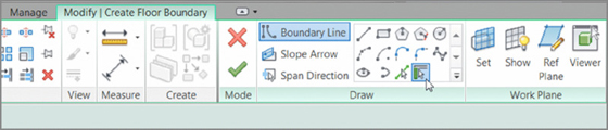
Figure 6.8 Picking walls ensures that that edge of your slab will move if the wall moves.
Let’s start sketching the slab.
- In the Modify | Create Floor Boundary tab, click the Pick Walls button, as shown in Figure 6.8, if it isn’t already picked.
- With the Pick Walls tool running, hover your mouse over the inside face of the wall.
- After the wall becomes highlighted and you’re sure you’re on the inside of the wall, pick it (see Figure 6.9).
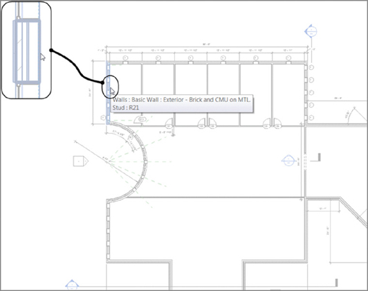
Figure 6.9 Picking the inside face of the first wall
- With the inside face of the wall picked, you need to move on to the next wall. Pick the inside face of the north wall.
- Notice that, as you pick the walls, a magenta sketch line appears on the inside face of the walls. This is another indicator telling you whether you’re on the correct side of the wall. The first line has two parallel lines, one on each side. These indicate the slab direction for structural decking.
- Keep picking the walls, as shown in Figure 6.10. You need to have a continuous loop—no gaps and no overlaps.
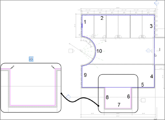
Figure 6.10 Selecting the walls
- Apply some basic modify commands as well. To clean the lower-right corner, use the Trim command. For the bottom line where the jog occurs, use the Split Element command. (Make sure the Delete Inner Segment button is selected on the Options bar.)
- After you’ve picked the perimeter of the west wing, click Finish Edit Mode on the Modify | Create Floor Boundary tab, as shown in Figure 6.11. It may be a good idea to check out your model in 3D after making floors just to make sure nothing went wrong. (I constantly have to do that.)
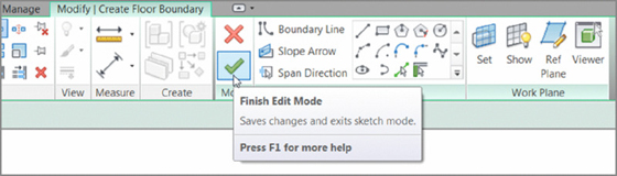
Figure 6.11 Clicking Finish Edit Mode to finalize the floor sketch
After you finish the floor, you’ll have plenty of opportunity to practice adding floors in this model. You need to add a floor to the corridor as well as the west wing. Follow these steps:
- Zoom into the corridor, as shown in Figure 6.12.
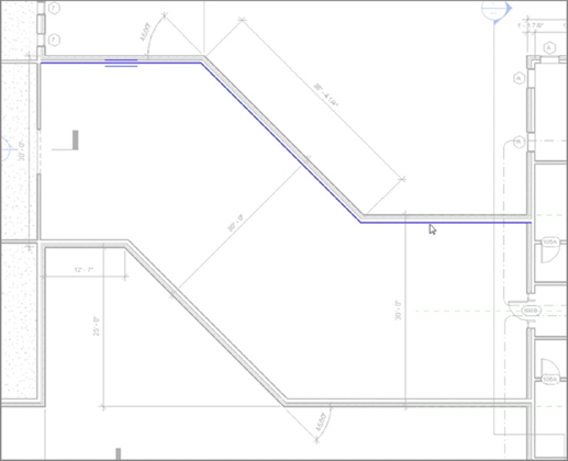
Figure 6.12 Picking the north walls of the corridor
- On the Architecture tab, start the Floor command.
- In the Modify | Create Floor Boundary tab, click the Pick Walls button.
- Uncheck Extend Into Wall.
- Pick the three north walls of the corridor. Remember to keep the blue line to the inside face (see Figure 6.12).
-
Revit may not let you pick the wall to add the east edge of the slab. If you do, the magenta line will go either to the core centerline or to the opposite face of the wall. At this point, click the Pick Lines button on the Modify | Create Floor Boundary tab, as shown in Figure 6.13.
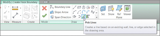
Figure 6.13 Sometimes you’ll need to click the Pick Lines button to select the edge of the slab. If you have to resort to this, however, the slab edge won’t move if the wall does.
- Pick the face of the east wall, as shown in Figure 6.14.

Figure 6.14 Picking the face of the east wall. The line will run past the corridor. That’s OK; you’ll trim it in a moment.
- On the Draw panel, click the Pick Walls button.
-
Pick the south corridor walls. (Remember to keep the magenta line to the inside of the corridor.)
- Pick the west wall of the corridor. This time you want to be sure the magenta line is to the left of the wall. This will ensure that the two slabs meet. If not, you may need to move the line manually (see Figure 6.15).
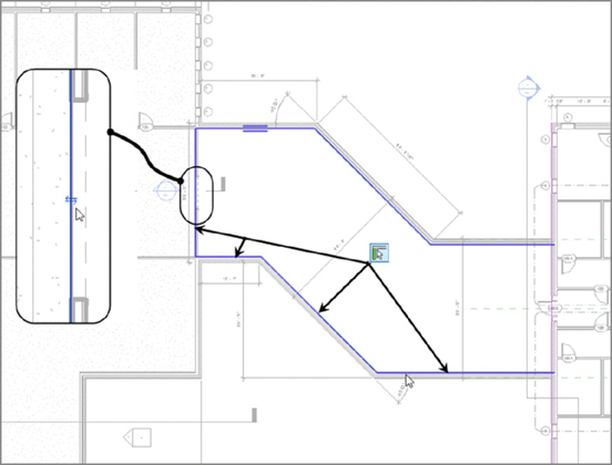
Figure 6.15 Adding the slab edge to the left side of the west corridor wall
Now that you understand the process of adding sketch lines to the model, you can start to look into how to clean up the sketch so you can finish.
Using Trim to Clean Up the Sketch
With the lines placed, you need to make sure you don’t have any gaps or overlaps. And you do. To fix these gaps and overlaps, you’ll use the basic modify commands from Chapter 5.
The east wall has a giant gap at the bottom and an overlap at the top. The command you need to use here is Trim.
- Pick the Trim/Extend To Corner button from the Modify panel, as shown at the top of Figure 6.16. Then click the portions of the two lines you want to keep. This removes the excess from the corner.
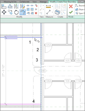
Figure 6.16 Pick the magenta lines in the numbered order illustrated in the figure.
-
With the corners successfully trimmed, click Finish Edit Mode.
When Revit allows you to finish the sketch, your west wing and corridor should have a continuous slab underneath them, as shown in Figure 6.17.
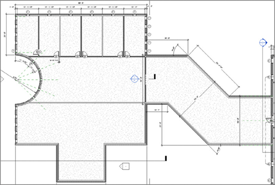
Figure 6.17 The two slabs under the west wing and the corridor
It’s time to add a slab under the east wing. Go ahead and try it on your own. Look at these directions only if you get lost:
- Zoom in on the east wing.
- On the Architecture tab, click the Floor button.
- In the Modify | Create Floor Boundary tab, click the Pick Walls button.
- Pick the exterior walls of the east wing.
- Trim any gaps or overlaps that occur in the corners, as shown in Figure 6.18. Also, pay special attention to the radial entry; it can be tricky.
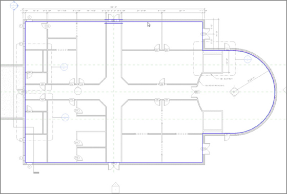
Figure 6.18 Adding a slab to the east wing
- Click Finish Edit Mode.
Now that you have a nice slab on the first floor, you need to add some more slabs to the rest of the levels. The trick with the slabs on upper levels is that they must extend into the core of the walls. This is where Revit can get sticky. Follow along with the next section, and let’s work out this issue together.
Building a Floor by Layers
As mentioned in the previous section, the term layer doesn’t equate to an AutoCAD layer. It does, however, equate to layers of materials used to design a floor system. When you create a floor system in Revit Architecture, you should do it with the mind-set of how a floor is actually constructed. You can also specify which material in the floor will stop at an exterior wall and which will pass through to the core.
In this section, you’ll build on your experience of creating a floor. With the concrete slab in place, you’ll start adding materials to create a floor finish.
Adding Materials
Your objective is to create a floor system with a structure and a finish material. You’ll also design the floor to interrupt the exterior framing, while letting the brick façade pass from grade to parapet. Let’s get started.
- In the Project Browser, go to the Level 2 floor plan. (Remember not to go to the Level 2 ceiling plan.)
- In the View Control bar (located at the bottom of the view window), be sure the detail level is set to Fine.
- On the Architecture tab, click the Floor button.
- In the Properties dialog box, click the Edit Type button.
- Click the Duplicate button.
- Call the new floor 6″ concrete with 1″ Terrazzo (see Figure 6.19). For metric users, it’s 150 mm concrete with 25 mm Terrazzo.
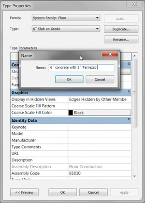
Figure 6.19 Duplicating the existing floor
- Click OK.
- In the Structure row, click the Edit button, as shown in Figure 6.20.
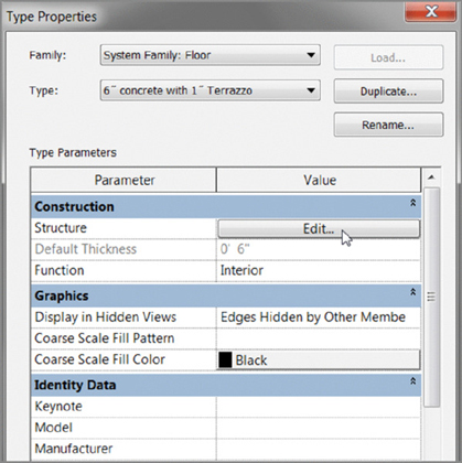
Figure 6.20 Clicking the Edit button in the Structure row
You’re now in the Edit Assembly dialog box, as you were in the previous procedure. The objective is to add 1″ (25 mm) Terrazzo flooring to the top of the 6″ (150 mm) concrete.
Adding a Layer
To add the additional material, you must understand how the Edit Assembly dialog box is broken down. Because you want to add a material to the top of the slab, you need to click above the concrete and insert a new layer, as follows:
- In the Layers field are three rows. Each row has a corresponding number. Click the number 1. This is the top row that reads Core Boundary | Layers Above Wrap (see Figure 6.21).
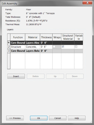
Figure 6.21 Inserting a new layer for the Terrazzo
- Under the Layers field, click the Insert button, as shown in Figure 6.21.
- The new layer is added. The field is now divided into columns. The first column is Function, which is currently set to Structure. This cell is a drop box containing the other available functions. Click the drop-box arrow, and select Finish 1 [4] (see Figure 6.22).
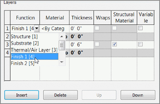
Figure 6.22 Choosing a layer function
- Click in the Material cell for the new Layer 1.
- Click the […] button.
- In the Material Browser, type terrazzo, as shown in Figure 6.23. Your Terrazzo material appears. When it does, select it, and click OK.
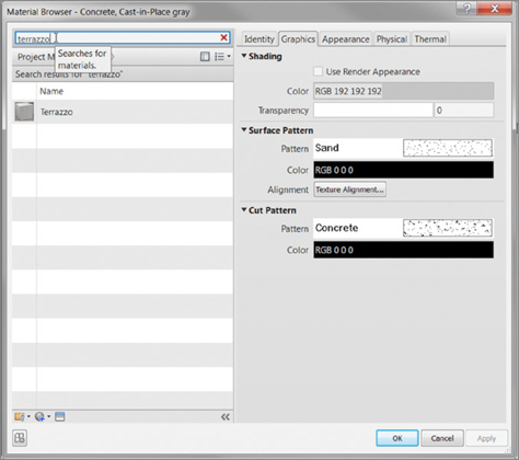
Figure 6.23 Selecting a material and adding it to the project
- Scroll down, and double-click Terrazzo (see Figure 6.23).
- Find the Terrazzo material in the top portion, select it, and click OK.
- Click OK.
- In the Thickness column, enter 1″ (25 mm). Imperial users, make sure you’re typing 1 inch and not 1 foot (see Figure 6.24).
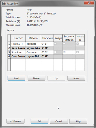
Figure 6.24 The completed layers for the floor system
- At the far right in the rows in the Layers field are Variable check boxes. Select Variable for the Structure row, as shown in Figure 6.25. This will enable you to slope the top of the slab if need be. Only the layer that is set to be variable will actually slope. Any layer that is on top of this variable layer will be pitched.
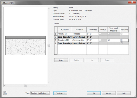
Figure 6.25 You can see a preview of the floor section as it’s being built.
- At the bottom of the Edit Assembly dialog box, click the Preview button. A graphic preview of your floor appears in a sectional view (see Figure 6.25).
- Click OK twice to get back to the model.
Great job—you now have a floor with a finish material on it!
Now you can place your new floor into the model. Remember that you’re on the second floor. When you place the slab, you want it to extend directly into the wall core. To do so, follow these steps:
- Click the Pick Walls button on the Draw panel. You’ll pick every exterior wall in the east wing except the radial wall.
- Start picking walls, as shown in Figure 6.26. Do not pick the radial wall at the east entry.
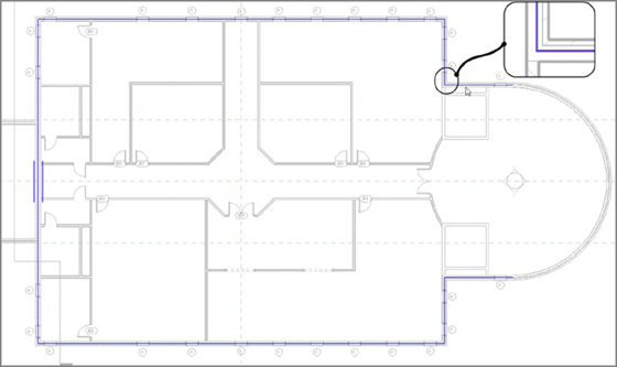
Figure 6.26 Picking the core centerline of the exterior walls, except the radial east wall
- On the Draw panel, click the Line button.
- Draw a line from the endpoint of the magenta line at the north wall of the east entry (see 1 in Figure 6.27) to the endpoint of the magenta line in the south wall (see 2 in Figure 6.27).
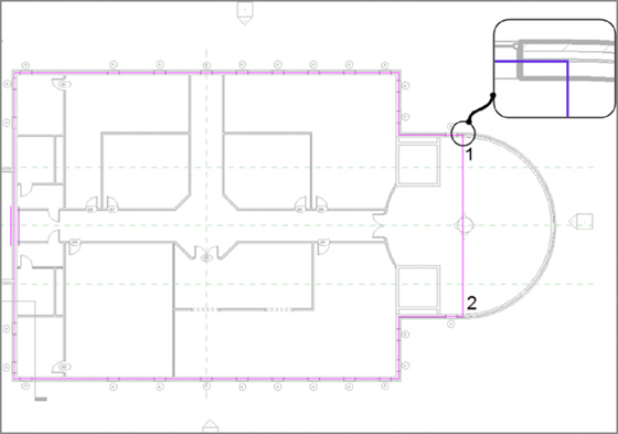
Figure 6.27 Sketching a line for the east portion of the entry slab
- On the Modify | Create Floor Boundary tab, click Finish Edit Mode.
- Revit begins asking you questions. First it asks whether you want to attach the walls that go up to Level 2 to the bottom of the floor. You do want to do this; this cuts the interior walls down to meet the bottom of the floor. Any change in the floor’s thickness will alter the tops of the wall. Click Yes, as shown in Figure 6.28.
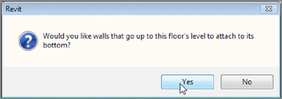
Figure 6.28 Click Yes to attach the walls to the floor’s bottom.
- The next message pertains to the exterior walls. Revit asks whether you would like to cut the section out of the walls where the slab is intersecting. In this case, you do, so click Yes in the message box, as shown in Figure 6.29.
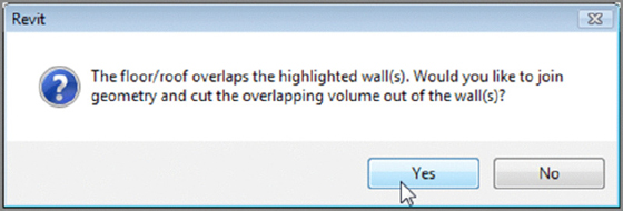
Figure 6.29 Click Yes if you want to cut overlapping volumes out of the exterior walls.
With the second floor in place, you can now add it to the floors above. To do so, you can use the Copy/Paste Aligned feature you used in Chapter 3, “Creating Views.” Try to do this on your own. If you don’t remember how or if you skipped Chapter 3, follow these steps:
- Select the floor in Level 2 if it isn’t still selected. (It’s easiest to select the floor at the east edge.)
-
On the Modify | Floors tab, click the Copy To Clipboard button on the Clipboard panel, as shown in Figure 6.30.
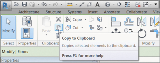
Figure 6.30 Clicking the Copy To Clipboard button
- Go to the default 3D view, as shown in Figure 6.31.
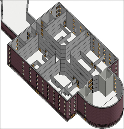
Figure 6.31 The walls on the floors above
-
From the Paste flyout on the Clipboard panel of the Modify tab, click Aligned To Selected Levels, as shown in Figure 6.32.
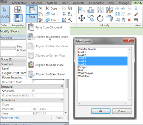
Figure 6.32 Selecting the levels where you want the slab to be copied
- The Select Levels dialog box appears, where you’ll choose the levels to which you want to paste your floor. Choose Levels 3, 4, and 5 (see Figure 6.32; use Ctrl to select more than one level).
- Click OK. The floors are pasted to the specified levels, as shown in Figure 6.33.
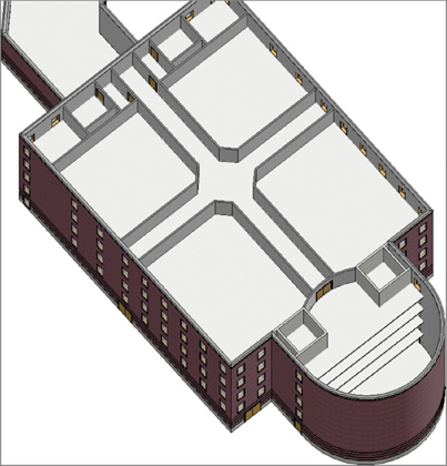
Figure 6.33 The completed floor placement
Notice that the fifth-level floor isn’t joined to any of the walls. This is because when you pasted the floor to this level, Revit didn’t prompt you to cut the overlapping geometry from the exterior walls. To fix this, follow these steps:
- After the floors have been pasted, select the fifth-level floor, as shown in Figure 6.34.
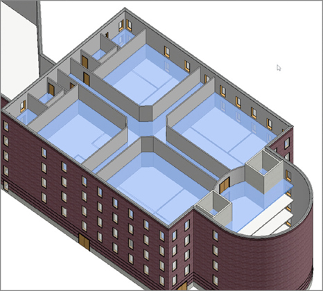
Figure 6.34 The fifth floor is now cutting the walls.
- On the Modify | Floors tab, click the Edit Boundary button.
- On the Mode panel of the Modify | Floors ➢ Edit Boundary tab, click Finish Edit Mode.
- Click Yes to attach the walls that go up to this floor’s bottom.
- Click Yes to cut the overlapping volume out of the walls. Figure 6.34 shows that the walls are now being cut by the slab.
- Repeat steps 1 through 5 for floors 4 and 3.
- Save the model.
Not too bad. You have a full building with floors placed. Now you’ll drill into these floors (literally) and see how you can make them perform to your specifications.
Your next task is to create different floor materials for a few specific areas such as the restrooms. You’ll then pitch the restroom floors to floor drains.
Splitting the Floor Materials
If you have a floor that includes a slab and you have a single material of, say, vinyl composition tile (VCT) for the entire surface, won’t that cause a problem in the restrooms? Better yet, suppose the floor is carpeted. Carpet never seems to perform well around a toilet!
Adding an Alternate Material
The goal of this procedure is to create a new material layer for the first-floor slab and then specify a new material for the restrooms. Follow these steps:
- In the Project Browser, go to the Level 1 floor plan and then zoom into an area of the east wing similar to the area shown in Figure 6.35.
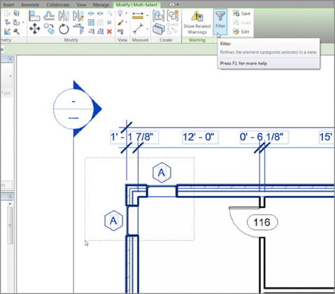
Figure 6.35 To select the slab, you’ll find it easier to pick an entire area and filter the floor.
- Drag a right-to-left selection window around the corner of the building, as shown in Figure 6.35.
- On the Modify | Multi-Select tab, click the Filter button (see Figure 6.35).
- In the Filter dialog box, click the Check None button, as shown in Figure 6.36.
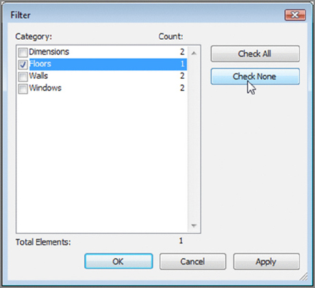
Figure 6.36 Deselect all the elements, and then select Floors.
- Select the Floors option (see Figure 6.36), and click OK.
- With the floor selected, click Edit Type in the Properties dialog box.
- Click Rename.
- Call the floor 6″ Slab on Grade with 1″ Finish (150 mm Slab on Grade with 25 mm Finish).
- Click OK.
- Click the Edit button in the Structure row, as shown in Figure 6.37.
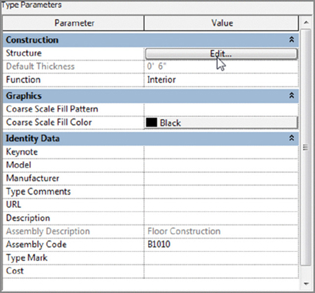
Figure 6.37 Editing the structure of the slab
- In the Edit Assembly dialog box, click the 1 button to the left of the Core Boundary item that is above the Structure layer, as shown in Figure 6.38.
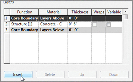
Figure 6.38 Adding a new layer
- Click the Insert button (see Figure 6.38).
- Select Finish 1 [4] from the Function drop-down list.
- Click in the Material cell.
- Click the […] button.
- Search for Carpet (1), and click OK.
- Give the material a thickness of 1″ (25 mm).
- In the Structure [1] row, select the Variable check box, as shown in Figure 6.39.
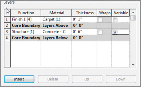
Figure 6.39 Adding the new material
- Click OK twice.
- Press Esc.
Now that you have experience adding a new material layer to the floor (you’ve done it twice in this chapter), you can specify a different material for the various rooms.
Splitting and Painting
Adding a new material to a floor is a two-part procedure. To specify an alternate material in an area, you must first split the floor’s face. Then you can add (or paint) the desired material to that area.
The objective of the next two procedures is to add an alternate material to the restrooms. Follow these steps:
- Zoom in on the lavatory north of the corridor.
- On the Geometry panel of the Modify tab, click the Split Face button, as shown in Figure 6.40.
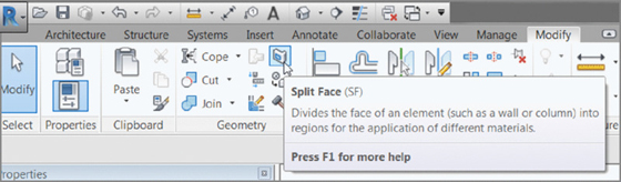
Figure 6.40 The Split Face button is located on the Geometry panel of the Modify tab.
- Move your cursor into the lavatory area, as shown in Figure 6.41.
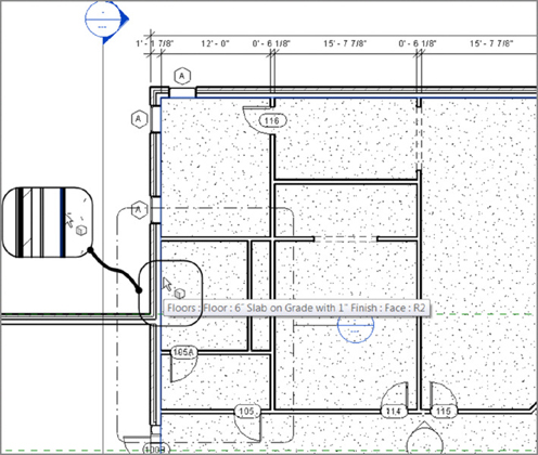
Figure 6.41 Finding the edge of the floor
- Notice the little cube at your cursor. Hover the cursor over the wall shown in Figure 6.41. You should get a tooltip telling you that you’re directly over the floor. When you see this indication, pick the floor.
- After you select the floor, you need to draw three lines around the inside face of the lavatory walls. To do so, on the Draw panel of the Modify | Split Face ➢ Create Boundary tab, make sure the Line button is selected.
-
Draw the three lines shown in Figure 6.42 (you may have to trim and extend the lines).
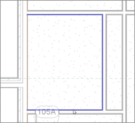
Figure 6.42 Placing the three split lines around the perimeter of the lavatory
-
On the Modify | Split Face ➢ Create Boundary tab, click Finish Edit Mode.
The lavatory area should now be split.
Although it appears as if nothing happened, you just can’t see it. The next series of steps will change the material of the region. At this point, it will become obvious that there is a different material.
The floor is split, and it’s time to add the new material to this room. This procedure is almost like adding a hatch to an area in AutoCAD. Here are the steps:
- On the Geometry panel of the Modify | Split Face tab, click the Paint button, as shown in Figure 6.43.
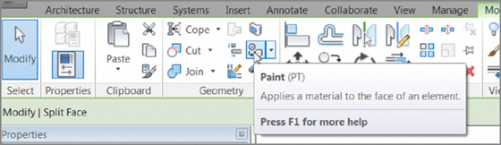
Figure 6.43 The Paint button on the Geometry panel
- From the material list, select Tile, Mosaic, Gray from the menu, as shown in Figure 6.44.
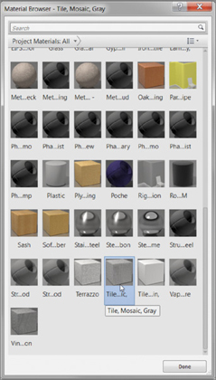
Figure 6.44 Finding the correct material
-
With the Material Browser still on the screen, move your cursor over the region you just created. Notice the Paint icon next to your cursor, as shown in Figure 6.45. The tooltip identifies the face region.
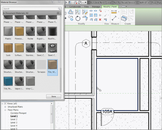
Figure 6.45 Filling the region with the new material
- When you see the perimeter of the small region you created around the inside of the lavatory, pick a spot. The area fills with the new material (see Figure 6.46). Click Done to close the Material Browser.
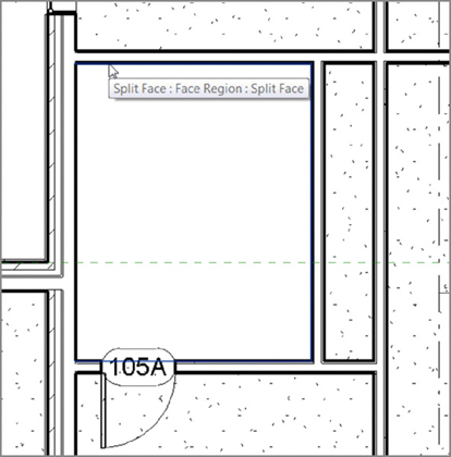
Figure 6.46 The completed lavatory
- Do the same thing to the lavatory south of the corridor. If you get stuck, go back through the steps.
- Save your model.
Next you’ll create a pitched floor situation. In some cases, this is an easy procedure. In others, it isn’t.
Pitching a Floor to a Floor Drain
Sure, it’s the responsibility of the plumbing engineer to specify what floor drains to use, but it’s generally the responsibility of the architect to specify where they’d like the floor drain. That being said, let’s move on to creating a pitched floor area in the restrooms. Because you have five floors with which to work, let’s go up to the second floor and start pitching some slabs!
The objective of this procedure is to add points in the surface of the slab in order to pitch to a drain:
- In the Project Browser, double-click the Level 2 floor plan. (Make sure you aren’t in the Level 2 ceiling plan.)
- Zoom in on the lavatory areas, as shown in Figure 6.47.
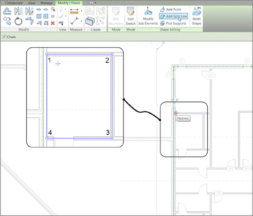
Figure 6.47 Drawing a split frame around the inside of the lavatory
- Select the floor.
- The Modify | Floors tab shows several choices. In the Shape Editing panel, click the Add Split Line button (see Figure 6.47).
- On the Options bar, click the Chain button.
- Draw lines along the finished inside face of the lavatory (see Figure 6.47). As always, there can be no gaps or overlaps.
With the split lines drawn, you’ve isolated the lavatory area from the rest of the floor. Now you can pitch the floor in this area without affecting the rest of the floor. The pitch will extend only as far as the split lines.
To create a drop in the floor, follow these steps:
- On the Architecture tab, click the Model Lines button (see Figure 6.48).
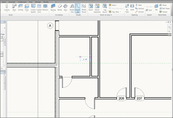
Figure 6.48 Drawing a line to establish the point to where the floor will slope
- Draw a line from the midpoint of the restroom’s right wall to the left 3′–0″ (900 mm), as shown in Figure 6.48.
- Press Esc twice.
- Select the floor. (Remember the Filter dialog box.)
- On the Modify | Floors tab, click the Add Point button, as shown in Figure 6.49.
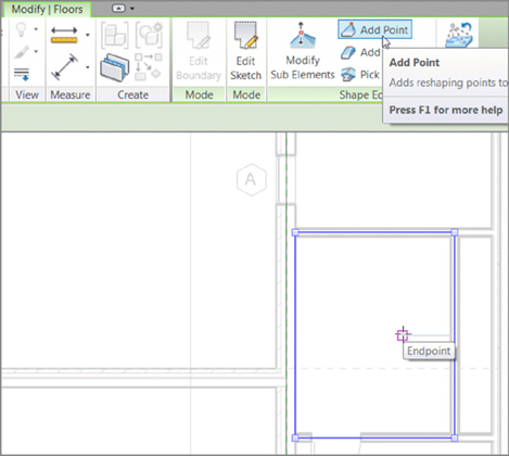
Figure 6.49 Picking the endpoint of the line
- Pick the endpoint of the line you just drew (see Figure 6.49).
- Press Esc once. This puts you in Modify Sub Elements Mode. You’ll know you’re in this mode by the icon next to your pointer, as shown in Figure 6.50.
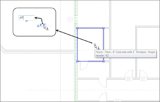
Figure 6.50 Dropping the elevation of the drain down 1″ (25 mm) from the surface of the floor
- Pick the point you just placed into the model. The point turns red, and a blue elevation appears. As you know, any blue item is modifiable. Click the 0′–0″ (0 mm) value, and change it to -1″ (-25 mm)—Imperial users, negative 1 inch.
- Press Enter. Revit drops that area of the floor and adds the slope lines as if you drafted them in.
- Press Esc twice.
- Delete the line you drew as a guideline.
-
Save the model.
See Figure 6.51: does your floor look like this? If not, go back and see where you went wrong.
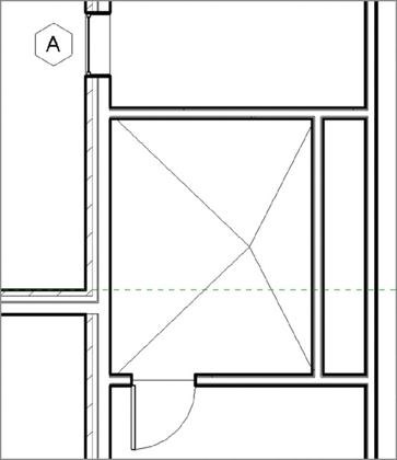
Figure 6.51 The final slab in the restroom
- Repeat the steps to add a pitch to the lavatory south of the corridor.
- Save the model (see Figure 6.52).
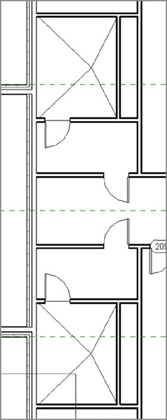
Figure 6.52 Both lavatories are pitched and ready to have fixtures added.
Now that you have experience in creating and placing floors, as well as pitching a floor in a specific area, let’s look at one more item: shaft openings.
Creating Shaft Openings
To create a shaft opening, you just create a void through your model. This void, however, can conform to walls that are set in the model. The elevator shaft walls, for instance, will define the outside edge of your shaft opening. You may notice that the floors you added to the model are indiscriminately running uninterrupted, straight through the shafts. You need to void the floor. Also, the good thing about creating a shaft opening is that if you create another floor, the shaft will be cut out automatically.
First, you need to create two more levels. You need a subterranean level (T.O. Footing) and a penthouse level, through which you’ll extend the elevator shaft. Follow these steps:
- In the Project Browser, go to the South elevation.
- On the Datum panel of the Architecture tab, click the Level button.
- On the Draw panel, click the Pick Lines button, and set an offset of 10′–0″ (3000 mm), as shown in Figure 6.53.
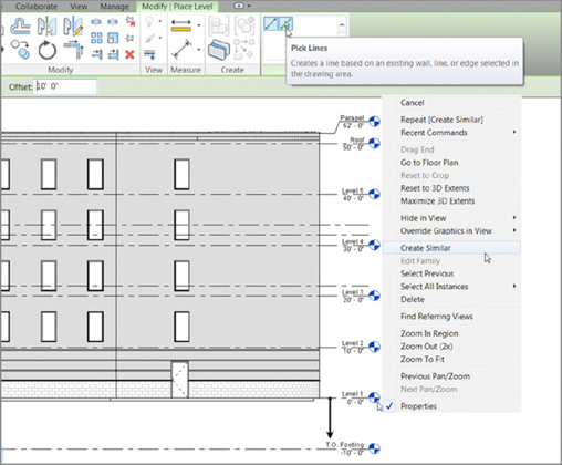
Figure 6.53 Adding a new Top of Footing level
- Hover your cursor over Level 1. Make sure the alignment line is below Level 1. When you see the alignment line, pick Level 1. You now have a new level at -10′–0″ (-3000 mm).
- Click the Modify button on the Select panel to terminate the command.
- Pick the level that is set to -10′–0″ (-3000 mm), and rename it T.O. Footing (see Figure 6.53).
- Click Yes when Revit prompts you to rename corresponding views.
The next step is to select the CMU elevator shaft walls and modify their properties so the bottoms are extended down to the top of the footing.
- Go to a 3D view.
-
Select all of the east entry elevator CMU walls. Remember to press and hold the Ctrl key as you select the walls.
- In the Properties dialog box, in the Constraints category, set Base Constraint to T.O. Footing, as shown in Figure 6.54.
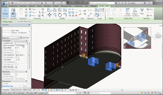
Figure 6.54 In the Properties dialog box, change Base Constraint to T.O. Footing.
- Click Apply.
With the bottom established at the correct level, it’s time to add the shaft.
- Go to the Level 1 floor plan. (Note that it doesn’t matter which floor you’re in when you place a shaft opening.)
- On the Architecture tab, click the Shaft button in the Opening panel, as shown in Figure 6.55.
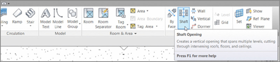
Figure 6.55 Clicking the Shaft button on the Architecture tab
- On the Modify | Create Shaft Opening Sketch tab, click Pick Walls, as shown in Figure 6.56.
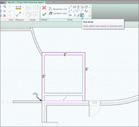
Figure 6.56 Adding the magenta lines to form the shaft opening to the outside of the CMU walls
- Pick the walls shown in Figure 6.56. Notice that you can have more than one shaft opening in the same command.
- Use the Line button on the Draw panel to draw the line across the inside face of the exterior wall.
- Use the Trim command to clean up any corners (see Figure 6.56).
- Mirror the lines you just drew up to the other shaft.
With the perimeter established, it’s time to choose which floors this opening will extend to. Just because you picked the CMU walls, this doesn’t mean a base and a top height have been established. Follow these steps:
- In the Properties dialog box, make sure Shaft Openings is selected, as shown in Figure 6.57.
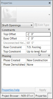
Figure 6.57 Setting the properties of the shaft opening
- In the Properties dialog, set Base Constraint to T.O. Footing.
- Set Top Constraint to Up To Level: Roof.
- Set Top Offset to -1′–0″ (-300 mm); this keeps the roof from having two giant square holes in it.
- Click Apply. Figure 6.57 shows the settings.
- On the Modify | Create Shaft Opening Sketch tab, click the Symbolic Line button. This will allow you to sketch an opening graphic into the shaft.
- Draw an X in both openings, as shown in Figure 6.58.
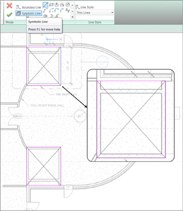
Figure 6.58 You can add any “drafting” symbolic lines you deem necessary.
- Click Finish Edit Mode.
The floor is now voided from the openings. Go to a 3D view, and look down the shafts. They’re wide open, as shown in Figure 6.59. The symbolic lines you drew will appear in the floor plans only.
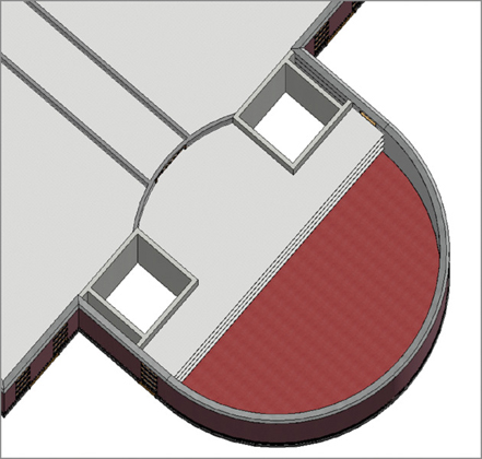
Figure 6.59 The completed shafts as seen in 3D
Now that you know how to pitch floors, you can begin using Revit for its unique capabilities. Also, you’re better prepared to move on to the next chapter, which focuses on creating roofs.
Are You Experienced?
Now you can…
- ✓ add a floor to your model by using the building’s footprint as a guide and by picking the walls and drawing lines
- ✓ add additional floors to higher levels by using the Copy/Paste Aligned method of quickly repeating the geometry up through the building
- ✓ add a specific, alternate material to different parts of the floor by using the Split Face command in conjunction with the paint materials function
- ✓ split a floor into segments and add additional points to set a negative elevation for pitching to floor drains
- ✓ create a shaft opening that will cut out any new floor slab
- ✓ use symbolic lines within a shaft opening to indicate the opening