Chapter 7
Schematic Design
Design inspiration comes from many sources. Some designers like to sketch by hand, and others use digital tools, but regardless, the design needs to align with the building program. Many modern sketches now happen digitally to make the transition from concept to schematic design easier.
When you begin to migrate your conceptual design from the sketch to the computer, don’t start with building elements (walls, floors, and so forth). Instead, start with more primal elements, a process called massing in the Autodesk® Revit® Architecture software, to make sure your program is correct. Once you’ve confirmed that the mass contains the required building program, you’ll be able to start placing building elements with far more confidence. Although massing is capable of much more complex form-making than you’ll see in this chapter, it’s a great starting point for learning Revit Architecture.
In this chapter, you learn the following skills:
- Working from a sketch
- Modeling in-place masses
- Creating mass floors
- Scheduling mass floors
- Updating the massing study
Working from a Sketch
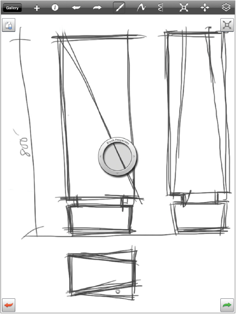
Sketches can be a great source for starting design massing in Revit Architecture. In certain cases, hand drawings can be scanned from physical pen-and-paper drawings. In some design workflows, sketching directly within a computer application is becoming increasingly common. To support this digital workflow, in 2010 Autodesk released a tool for Apple’s iPad called SketchBook Pro (see Figure 7.1) that allows you to sketch directly on a tablet or mobile phone using a stylus or even your finger.
The sketch in Figure 7.1 was created on an iPad, but the sample scenario for this chapter will work for any scanned sketch design, even one on tracing paper. In this example, the designer has created sketches of a proposed building form and would like you to import each of the view orientations (plan and elevations) into Revit Architecture and use them as context for a quick massing study. The building program allows a maximum building height of about 800′ (244 m) and requires a gross area of 3.5 million square feet (325,000 square meters).
Importing Background Images
Let’s look at how you can combine the design’s sketches with the Revit Architecture massing tools to help deliver preliminary feedback about the design. When you open Revit Architecture for the first time, you’ll find yourself at the Revit Architecture home screen. This screen keeps a graphic history of the recent projects and families that you’ve worked on. Now, follow these steps:
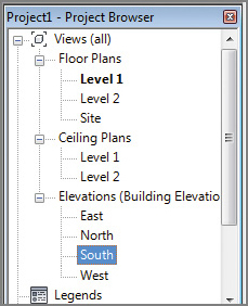
1. On the home screen, select Architecture Template to open one of the default Revit Architecture templates. Open the South elevation by double-clicking South in the Project Browser (see
Figure 7.2).
2. On the Insert tab, select the Import panel, and click the Image tool.
3. Select the
c07 Massing Sketch.png file from the
Chapter07 folder on this book’s web page (
www.sybex.com/go/revit2014essentials). When you select the image, you’re put back in the South elevation view.
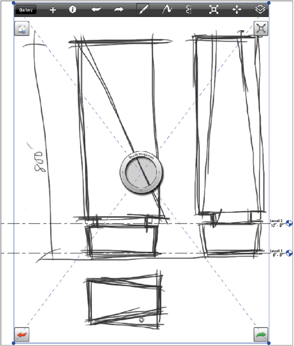
4. You see a large, empty-looking box with an
X through it. This is the Image Placement tool. Place the image as shown in
Figure 7.3 so that the base of the building sketch roughly aligns with Level 1.
As you can tell from Figure 7.3, the scale of the sketch doesn’t relate to the real-world units of Revit Architecture. To remedy this, in the next section you’ll quickly scale the imported image.
Accurately Scaling Images
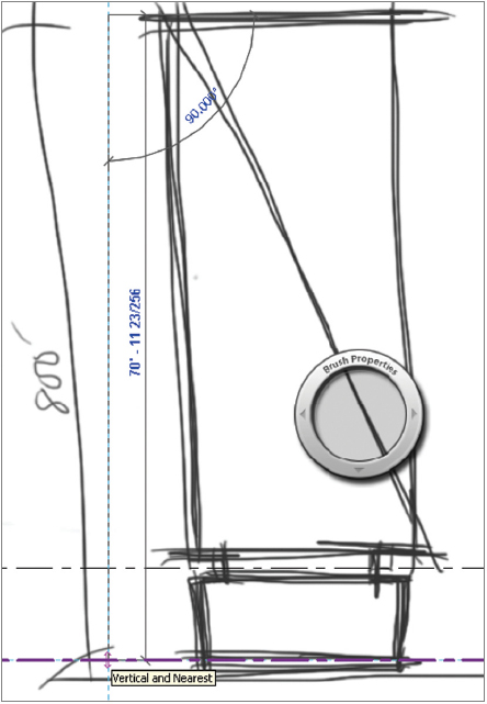
Select the Measure tool  on the Quick Access toolbar (QAT) located at the top of the screen. When the tool is active, pick between the two points, as shown in Figure 7.4. As you can see, the real-world distance in the image is about 70′ (52 m). Depending on how you inserted your image, your dimension might vary a bit. That’s fine; your next step is to learn how to scale these images.
You know the desired distance is 800′ (243 m) between the two points you just measured. One way to change the image size is to select the image and manually enlarge it by dragging the corner grips until the distance is correct—and in many cases this might be close enough. However, we’ll show you a more precise method.
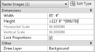
1. Select the image, and look at the Properties palette on the left. Notice the current dimension for the Height field is 113′ 9″ in the example. To modify the image size, you need to increase the Height value with regard to the desired and actual dimensions.
2. To determine this value, use this formula:
Current Height × (Desired Height / Measured Distance)
So, for this example, you’d use the following:
113′-9″ × (800′ / 70′) or (26 m × (243 m / 52 m)
Using the built-in database functionality of Revit Architecture, you can do this math right in the Properties palette, as shown in
Figure 7.5. Be sure to add the = sign at the beginning of the formula. The height of the image increases significantly (more than 975′ [2,735 m]). But now the imported image has proportionally increased the correct amount.
3. Move the sketch to align with Level 1 again (the arrow keys on the keyboard are useful for this). Also, increase the scale of the view to 1″ = 40′-0″ so that the level symbols are more visible.
Using Reference Planes and Levels
Reference planes are one of the most useful tools in Revit Architecture. The planes are represented in Revit Architecture as green dashed lines, and they display in any view perpendicular to the reference plane. They don’t print in your drawing sheets, but they’re handy as a tool to align elements that are coplanar. Think of them as levels and grids, except that you don’t need to show them on your sheets.
In the example, it’s important to use reference planes as guides to help you create the masses in other views, because the image you imported will be visible only in the imported view. Reference planes are like guidelines that can be seen across many views. They will be extremely helpful when you line up the sketch in the South elevation and then in the North elevation or plan view.
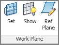
1. To begin, click the Architecture tab, and on the Work Plane panel, select the Ref Plane tool. Click once, and then click again to draw a vertical line in the canvas. Draw a total of six vertical reference planes like in
Figure 7.6.
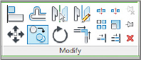
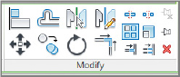
2. Selecting the reference planes can be difficult when an imported image is present. At this point, you should select the image and then click the Pin tool

in the Modify gallery of the ribbon; this will keep the image from accidentally moving. Now, under the Modify button, click the Select button, and then uncheck the Select Pinned Elements button. The image will no longer interrupt your workflow.
3. Select the far-left reference plane; in the Properties pane, find the Name parameter and type in Upper Mass. Name the second reference plane Base Mass. Name the third reference plane Middle Mass. Name the fourth reference plane Middle Mass 2. Name the fifth reference plane Base Mass 2. Name the last reference plane Upper Mass 2.
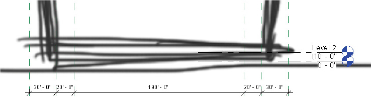
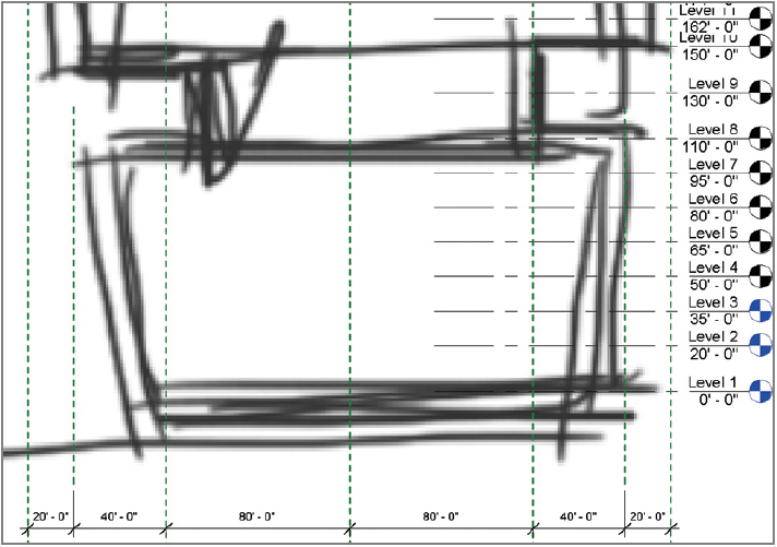
4. You will dimension the distance between these planes. Select the far-left reference plane. On the Measure panel of the ribbon, choose the Aligned Dimension tool. Click each of the reference planes; then click once more to place the dimension string below the sketch.
5. The dimensions are not round numbers, so you’ll change that. Click the second reference plane; then click the blue dimension between the first and second reference planes, and type in
30. Now select the third reference plane, click the blue dimension between the third and second, and type in
20. Follow the same steps with the other reference planes to achieve the result in
Figure 7.7.
Now you’ll add some levels to the file that will be useful for determining the limit of the three masses you’ll add.
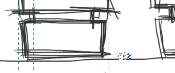
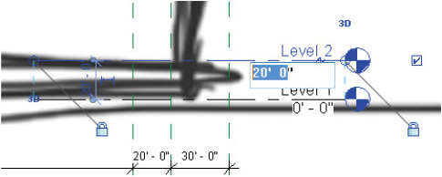
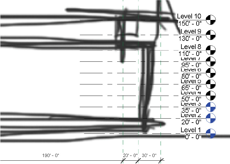
1. Move Level 2 by selecting the Level element; then click the blue 10′-0″ (3 m) text. Now type in the new elevation of
20’ as in
Figure 7.8.
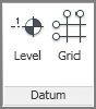
2. To add levels, select the Architecture tab, and then choose the Level tool on the Datum panel. By clicking and dragging your cursor from left to right, you create a level that also creates a corresponding floor plan. Place Level 3 at 35′-0″ (10 m).
3. You can also create levels by copying an existing level. Start by selecting level 3; then, on the Modify panel in the Ribbon, click the Copy tool. Click the Multiple check box on the Options Bar. Click to start the tool then again to place the copied level.
Levels vs. Reference Levels
Using the Copy tool doesn’t create a corresponding floor plan. Rather, it creates what Revit Architecture calls a reference level. Reference levels aren’t “hyperlinked,” and they show black level symbols. Levels that have corresponding floor plan views are blue in elevations and sections. If you double-click the blue level marker, Revit Architecture opens the floor plan view.
In
Figure 7.9, Levels 1–3 have corresponding floor plan or level views, whereas Levels 4–10 are reference levels only. Reference levels can be turned into view levels, but during the design process (and later in documentation), you’ll find it helpful to create levels that don’t need to be views. Having 100 or more view levels would create a lot of clutter in your drawing set.
Now you’ll create the rest of the levels, as shown in Figure 7.9, by arraying Level 10.
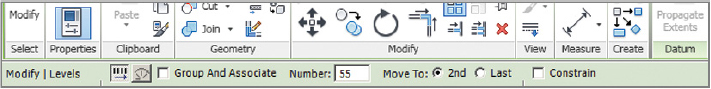
1. Select Level 10. The Modify | Levels menu becomes active. Select the Array tool on the Modify panel.
2. Because Level 10 is at an elevation of 150′-0″ (45 m), you need to create an array with the options shown in
Figure 7.10. These options can be adjusted in the Options Bar below the ribbon.
3. Pick a location that is directly 12′-0″ (3.6 m) above Level 10. When you click to place the 11th level, the additional 55 levels are created automatically. Your final level (Level 64) appears at 798′-0″ (243 m). That’s pretty close to your goal of 800′-0″ (243 m).
Creating and Placing Groups
In this exercise, you’ll create a group and explore potential uses for the Group command.
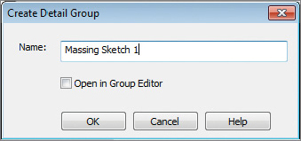
1. Select the image you inserted earlier in the South elevation, and then select the Group tool on the Create panel on the ribbon.
2. When the Create Detail Group dialog opens, name the group
Massing Sketch 1, as shown in
Figure 7.11, and click OK.
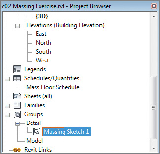
3. Find and open the East elevation from the Project Browser. Now find the Groups node in the Project Browser. Click it and then Detail to see the group you just created (see
Figure 7.12). By clicking and dragging this group into your project window, you can add the detail group to other views in your project.
4. Drag a copy of the detail group from the Project Browser into the view. Change the view scale to 1″=40′. Then create some more reference planes on the other elevation sketch, as shown in
Figure 7.13.
5. Open the Level 1 view, and then drag a final copy of the detail group into the view. Now center the plan sketch in the reference planes you created, as shown in
Figure 7.14. Now you have the three views necessary for massing the building.
Images and Groups
Each image you import in Revit Architecture can be seen only in the view in which it’s placed. In other words, an image placed in the South elevation view is seen only in that elevation view. In the example, you’re trying to assemble a 3D context for modeling geometry, and you’ll need to place the image in multiple views.
When you change the scale or proportion of one of the images, you’ll likely want to change all of them. Groups are used in Revit Architecture to maintain relationships between collections of elements. When one group changes, all the groups change. This is very helpful for collections of components that are compiled into units, such as furniture layouts, hotel rooms, and apartment types.
Modeling In-Place Masses
Now that you’ve imported the designer’s sketch and drawn the appropriate reference planes for added context, you can start creating the massing elements that will represent the building. You’ll do so using a tool called In-Place Mass. Consider masses as families in Revit Architecture that are created directly within the project. This tool allows you to model within the context of the project you’re actively working in.
Modeling the Base Mass
1. Open your Level 1 floor plan view by double-clicking Level 1 in the Project Browser.
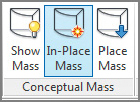
2. Select the Massing & Site tab on the ribbon, and select the In-Place Mass tool on the Conceptual Mass panel. If you don’t see the Massing & Site tab, don’t fret. Click the Application button, and select Options. On the User Interface option, you can check the Massing & Site box.
3. Revit Architecture displays a dialog telling you that it has now enabled the Show Mass mode in the current view. Click Close.
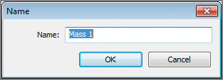
4. The Name dialog appears. For this exercise, use the default name, which is Mass 1 (see
Figure 7.15). Click OK.
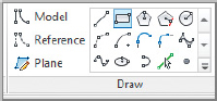
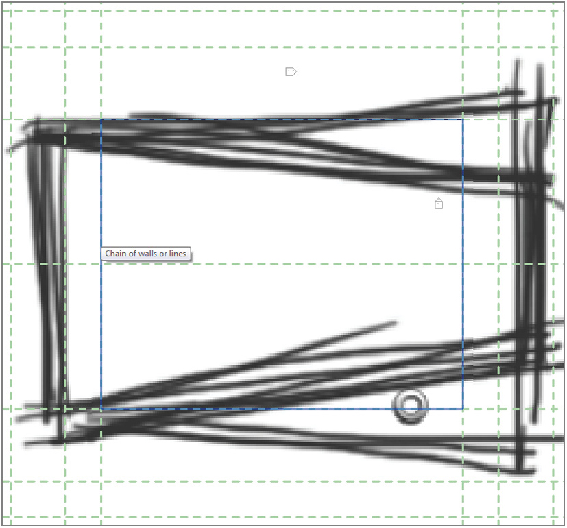
5. Now you’re in a special, in-place editor for creating masses in Revit Architecture. Notice that the menu options have changed. Select the Rectangle tool.
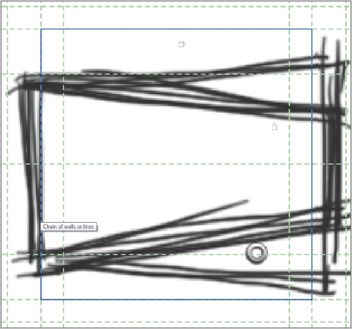
6. Using the Rectangle tool, sketch some lines as shown in
Figure 7.16. These lines should cover the form and be placed along the reference planes you created earlier.
7. Select the lines, and then select the Create Form tool on the Form panel.

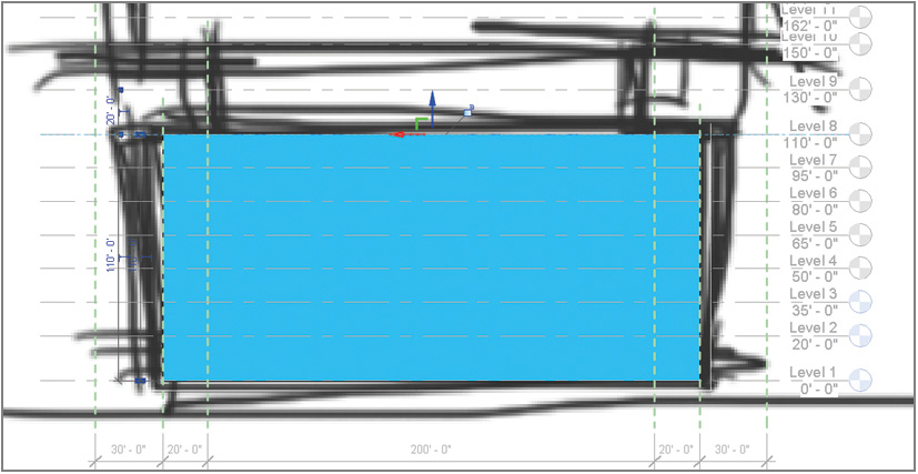
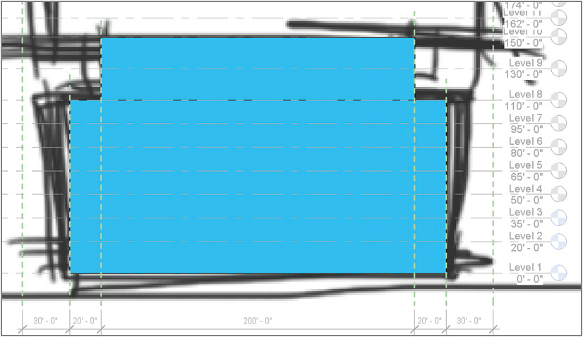
The results aren’t immediately obvious because you’re looking at a solid form in plan view. To view the results from another angle, return to the South elevation. Select the top of the form by clicking it, and use the grip arrows, as shown in Figure 7.17, to increase the form’s height until it aligns with Level 8. The edge of the forms will “stick” to the level when you’re close and snap itself into place.
Sketching Masses
The type of mass you’re creating in this exercise is called an extrusion. There are many other configurations of masses, including blends, sweeps, swept blends, and revolves. After you’ve created the initial mass, it’s possible to edit the form dramatically; you can even use voids to carve away at your initial form.
We don’t have the space to go into that level of complexity. But modeling more complex masses is something that you’ll likely want to learn. Check out http://au.autodesk.com/?nd=class_listing.
Modeling the Middle Mass
The next step is to model the middle mass form.
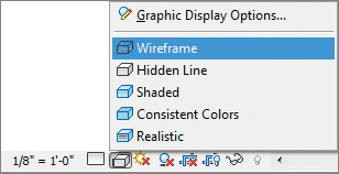
1. Return to the Level 1 plan view. Set the view to Wireframe, as shown in
Figure 7.18 (so you can see through the mass you’ve just created). The Wireframe button is located in the View Control Bar at the bottom of the screen.
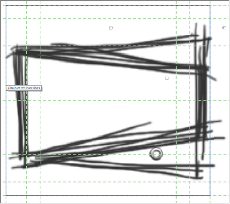
2. Using the same workflow, sketch another rectangle, as shown in
Figure 7.19. Then select the rectangle and click Create Form, as you did with the previous rectangle.
3. Open the South elevation, and use the grip arrows to move the second mass form so the upper face aligns with Level 10. Use Wireframe to see through the first mass to the second mass. Select the lower edge and drag it so it aligns with Level 8, as shown in
Figure 7.20.
Modeling the Upper Mass
The process of creating the third (and uppermost) mass starts the same as for the first two masses.
1. Return to Level 1, and create a rectangular sketch that connects the outermost reference planes, as shown in
Figure 7.21. Then select the lines, and click Create Form.
2. Return to the South elevation, and use the grip arrows to extend the top and bottom of the form. Extend the upper and lower faces to align with Levels 64 and 10, respectively.
You could continue to work in 2D views, but it’ll be more helpful if you can see what you’re doing in 3D.
Working in 3D
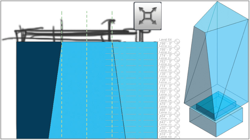
Select the Default 3D View icon from the QAT  . Doing so allows you to see the working mass more completely, as shown in Figure 7.22.
You likely noticed from the imported sketches that the East façade of the mass should taper in elevation. The base and the top are different widths. By adding an edge to each face (both North and South or Back and Front on the ViewCube), you’ll be able to adjust the upper form.
1. Hover over the South face of the upper form, and select the face by clicking it. Doing so activates the Add Edge tool on the Form Element panel.
2. The Add Edge tool divides one plane on the mass by adding another edge that can be adjusted independently of the other edges. Add the edge at the front, lower corner of the upper mass, as shown in
Figure 7.23.
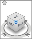
3. Rotate the model to expose the North face. Do so by selecting the intersection of the ViewCube between the right, back, and top sides. The model will spin around and center itself.
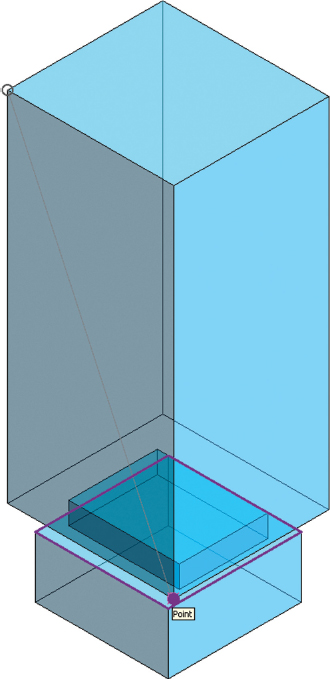
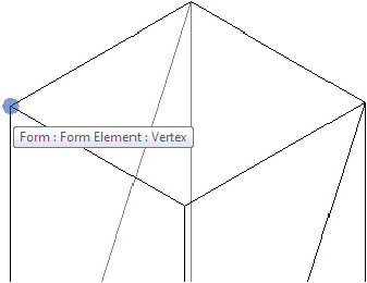
4. Select the North or Right face to add an edge from the top-right corner to the lower-left corner (see
Figure 7.24).
5. As you hover your mouse pointer over the right face’s top-left intersection, a vertex control appears as a purple dot (see
Figure 7.24).
6. Select this control, and use the grip arrows to move it toward the center of the face. Next, do the same thing to the other corner of the face. The result will resemble
Figure 7.25.
7. Your mass is nearly complete, but first you need to join all the mass geometry together. Select the Join tool on the Geometry panel. Then select the lower and middle forms to join them. Repeat this process for the middle and upper forms.
8. Now that the forms have been joined, select the Finish Mass tool in the In-Place Editor panel. It’s the big green check mark

, meaning you’re done!
Congratulations! You’ve just created your first massing study.
Joining Masses
Each mass is an independent object. Masses can even be scheduled independently from each other. You’ll find this functionality helpful for creating separate masses for programming purposes (such as convention space or meeting rooms). But be careful if you have overlapping masses.
If overlapping masses aren’t properly joined, Revit Architecture will create overlapping mass floors, and your schedules will be incorrect. Furthermore, if you create real floors from the mass floors, the floors will overlap rather than create a single element.
Creating Mass Floors
Floor area faces are incredibly useful for getting a sense of the gross area of a building mass at any intersecting level. Furthermore, the results can be quickly and easily scheduled. Any changes to the massing study will update the schedules and all views in real time.
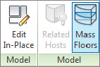
Select the completed mass, and then click the Mass Floors tool in the Model panel. You’re given the option to select all the levels in your project. You want to select them all, but rather than select them one at a time, select Level 1, and then scroll down. While pressing Shift, select Level 64. Now all of the levels are selected. Check any box, and all the boxes are automatically checked. Click OK.
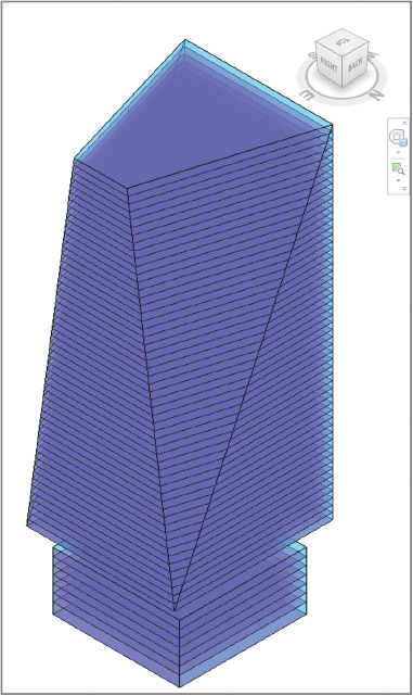
Your mass has now been bisected with mass floors (faces with no geometry), as shown in Figure 7.26.
Scheduling Mass Floors
Creating schedules in Revit Architecture is easy. Doing so allows you to understand the impact of your work while you work—rather than at the end of a long design process. Schedules can help you not only track elements in Revit Architecture but also assess how conceptual design work meets your program requirements.
Schedules are just like any other type of view in Revit Architecture—they show you a current, specific look at the model. These views show you this information in a spreadsheet format, but just like the other view types, schedules dynamically update as changes are made to the model. Follow these steps:
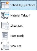
1. To create the mass schedule, select the View tab on the ribbon. Then select the Schedules drop-down in the Create panel. Click Schedules/Quantities.
2. In the New Schedule dialog, find the Mass category, and expand it. Now select the Mass Floor option in the column on the left, and leave the other fields (Schedule Name and Phase) at their default values. Click OK.
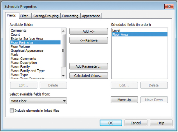
3. The next dialog contains a series of tabs. You’ll step through some of these to set up the schedule. On the Fields tab, select the following from the list on the left:
Level
Floor Area
You can double-click these to move them to the box on the right, or you can highlight them and click the Add button (see
Figure 7.27).
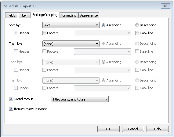
4. On the Sorting/Grouping tab, change Sort By to Level. Also, check the box at the bottom for Grand Totals, and select Title, Count, And Totals in the drop-down, as shown in
Figure 7.28.
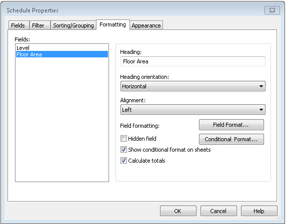
5. On the Formatting tab, select the Floor Area field, and then click the Calculate Totals option (
Figure 7.29). Click OK. This creates the schedule.
Figure 7.30 shows the resulting schedule. With a total of 63 floor levels, Revit Architecture is calculating a gross floor area of just more than 4.5 million square feet (418,000 square meters).
Unfortunately, you know from the program (at the beginning of this chapter) that the gross floor area needs to be closer to 3.5 million square feet (325,000 square meters). So, let’s get back to that massing study and tweak the form to get it closer to the program goals.
Updating the Massing Study
Begin by selecting the mass in the default 3D view and then clicking the Edit In-Place button in the Model panel. Doing this returns you to In-Place editing mode and allows you to have specific control over mass geometry.
You’re going to modify the east and west faces, moving each face 40′-0″ (12 m) closer to the center. Hover your mouse near the edge of the face of the upper mass. Select the face, and note the small temporary dimension and the 3D widget.
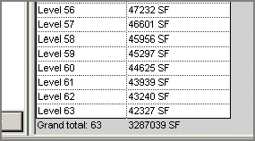
Click the blue text, and change the value to 260′-0″ (80 m). Do the same for the middle and lower east faces. Click the Finish Mass button on the ribbon to confirm your edits. Go back to the Schedule view. Note the gross floor area is closer to 3.25 million square feet (see Figure 7.31), or about 302,000 square meters.
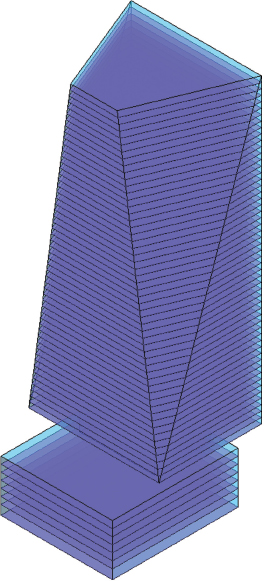
You will need the program to be closer to 3.5 million square feet. A quick discussion with the designer reveals that the base of the building is meant to hold important meeting and conference spaces. So, you’ll extend the eastern base of the building back to 300′ (91 m). Once again, you do so by repeating the previous steps of selecting the mass and returning to In-Place editing mode. When this is finished, the mass looks like Figure 7.32, and the gross floor area is within the required program.
If you want to download the completed Revit Architecture file, you can find it in the Chapter07 folder on the book’s web page. The file is called c07 Massing Exercise.rvt.
The Essentials and Beyond
Ultimately, masses can be used to host relationships to real building elements that would otherwise be nearly impossible to maintain. Mass floors can be used to control the extents of real floors. Many times, this will allow you to change location of many slab edges at once by changing the mass and then updating the floors within that mass.
Masses can also host walls, curtain walls, and roofs. This allows you to create (and modify) complex design forms that would be nearly impracticable to assemble bit by bit. The idea is that you’re working from general to specific: get the big ideas down first (as masses), and then go back and assign real building elements to those faces to build the building.
But keep in mind that it’s unlikely you’ll be able to use only one mass to host all your building elements. You may need one mass to host floors and control slab edges, another to host roofs, and even another to host walls and curtain wall systems. Don’t be afraid to use overlapping masses in these situations to control different host elements. More specific control will often require overlapping masses. But for initial design/programming purposes, using a single mass to resolve gross floor areas is often sufficient.
Additional Exercises
- After you’ve created your mass and mass floors, use the Floor By Face tool to assign real floors to the mass floors.
- Modify the mass and remake the geometric floors that you created in the previous item.
- Experiment with walls and curtain walls by using the Wall By Face and Curtain System tools to assign walls to the face of the mass.
- Modify the mass and remake the walls and curtain walls created in the previous item.
- Explain what you would do if you wanted to control floors and walls with a mass but the floors and the walls didn’t always align. For example, what would you do if the floors were set back or deviated from the face of the mass?