
Chapter 12
Creating Drawing Sets
While the industry continues to move toward a building information model as a contract deliverable, today we still need to produce 2D documents for most construction and permitting purposes. Using the Autodesk® Revit® Architecture software, you can create these sets with more accuracy and dependability than in the past.
In this chapter, we’ll introduce a scenario that will mimic what might happen on a real project in preliminary design. You’ll be using the c12-Residence.rvt model from the book’s web page (www.sybex.com/go/revit2014essentials) in the Chapter12 folder.
Here’s the story. You have recently completed some design work in advance of your upcoming pricing package for a residential design project. You will need to present the plans, elevations, and perspectives on some sheets for the package. But you want to help the contractor by providing some quantities, so you will also include schedules.
In this chapter, you learn the following skills:
- Creating schedules
- Placing views on sheets
- Printing documents
Creating Schedules
Schedules are lists of elements and element properties in the model. They can be used to itemize building objects such as walls, doors, and windows; calculate quantities, areas, and volumes; and list elements such as the number of sheets, keynotes, and so on. They are yet another way to view building objects in a model. Once created, they are dynamically kept up-to-date with any changes that occur to the model itself.
Understanding Schedules
In a project workflow, creating schedules of model elements, areas, or other objects is usually one of the most laborious tasks for architects. When this process is performed manually, it can take a very long time and typically results in errors requiring much checking and rechecking of the information. In Revit Architecture, all the elements have information about their properties defined in the model. For example, doors have properties such as size, material, fire rating, and cost. All this information can be scheduled and quantified. As those doors are changed, the properties update in the schedule.
Because Revit Architecture is a bidirectional parametric modeling program, you are also able to make changes to element properties in a schedule — updating the model and all other views automatically. Continuing with the door example, you can change the material of a door in the door schedule, and the material tags and rendering view will be instantly updated.
You can access several types of schedules from the Create panel of the View tab. Let’s look at each of the six primary types of schedules.
Choosing a Schedule Category
Each of these schedule types has a host of categories that you can mix and match to track elements in the model. You can adjust several aspects of these schedules to build and customize your schedules to meet your needs. Let’s step through these aspects and see how they can be used.
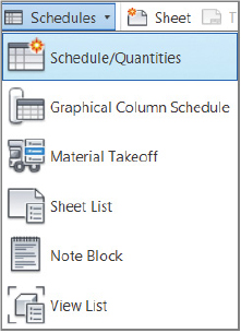
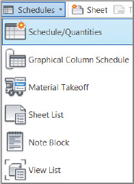
Go to the View tab, then go to the Create panel, then select the Schedules flyout, and select Schedule/Quantities. The New Schedule dialog box appears, allowing you to select a category to schedule (Figure 12.1).
FIGURE 12.1 Creating a new schedule
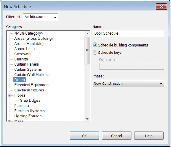
If there aren’t enough categories for you to choose from to create a schedule, there is a venue to add additional options. At the top of the New Schedule dialog box is a Filter List drop-down that gives you the ability to schedule elements from the mechanical, electrical, and plumbing (MEP) and structural categories. This option can be useful when those disciplines are supplying model files to you and you are linking them into your architectural model.
You also have the opportunity to create schedules that span multiple categories. The first option in the Category list in Figure 12.1 is Multi-Category. You might want to schedule all the casework and furnishings in a project simultaneously. Or perhaps you want to schedule all the windows and doors if they are being ordered from the same manufacturer. One of the limits of this schedule type is that you cannot schedule host elements such as walls, floors, and ceilings.
Customizing Schedules
With this description in mind, let’s look at the other options when creating a schedule. Choose Walls from the Category list, rename the schedule Door Schedule, and click OK. Doing so opens a new dialog box called Schedule Properties. Here you can set the various properties of a schedule that define not only how it looks but also what information it reports.
Five tabs appear across the top: Fields, Filter, Sorting/Grouping, Formatting, and Appearance. Each of these controls different aspects of the schedule. Let’s step through these tabs and see how they affect the look and reporting of the schedule.
FIGURE 12.2 The Fields tab
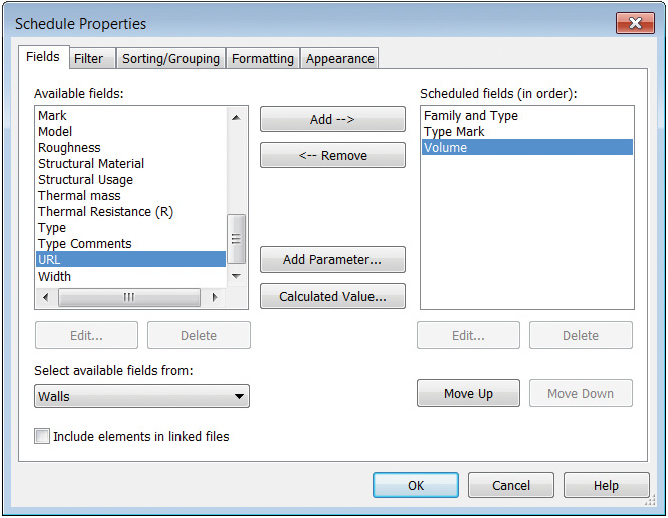
FIGURE 12.3 The Filter tab
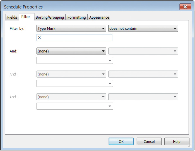
FIGURE 12.4 The Sorting/Grouping tab
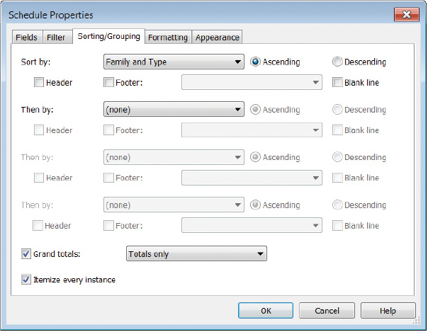
FIGURE 12.5 The Formatting tab
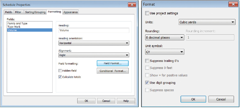
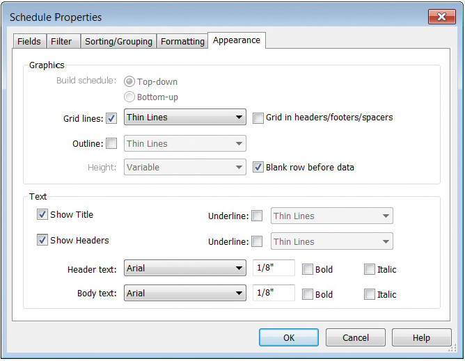
FIGURE 12.6 The Appearance tab
Once you’ve established the fields and look of your schedule, click OK to view the working schedule. This layout can be modified at any time, but it gives you a basis from which to begin. To modify the schedule, use the buttons in the Properties palette to access any of these five tabs. You will see the final graphic formatting of the schedule only when it is placed on a sheet. We’ll get to that later in this chapter.
Using Ribbon Commands in a Schedule
Schedules have their own special tab on the ribbon that is active when you are viewing the schedule outside of a sheet. The tab (Figure 12.7) allows you to insert, delete, and resize rows; show or hide columns in the schedule; and control the appearance of titles, headers, and body of the schedule. The commands become available as you click in the schedule header field, column label field, or row of data.
FIGURE 12.7 The Schedule tab buttons
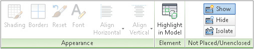
Another key feature of this menu bar is Highlight In Model. This button allows you to select any element in the schedule and locate that element in the model. Let’s say you want to locate a particular wall segment from your wall schedule. Highlight the wall in the schedule, and click the Highlight In Model button; you will be taken to a different view with that wall instance highlighted.
Now that you have an idea of the elements that compose a schedule, let’s return to the demonstration workflow and create a window schedule, a room schedule, and a sheet list.
Making Schedules
Continue using the c12-Residence.rvt model from the book’s website. You’ll notice that several views and sheets are already created. This model is a work in progress — it’s a private residence of 1,230 square feet. The project is a renovation of an 1890s two-story brick house. In the design, all the interior walls have been eliminated and put on a demo phase, which keeps the 19’ (6 m) clear span as open as possible. All new interior walls have been added, and the entire interior has been refreshed in the historic shell. Because the renovation is so substantial, the designer chose to replace all the existing original windows with insulated, wood windows.
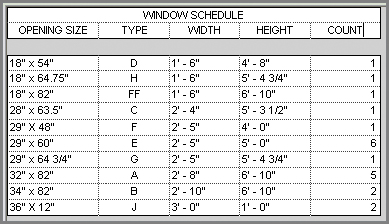
Creating a Window Schedule
To assist the window manufacturer with the custom sizes, you need to create a window schedule. To begin, go to the View tab, go to the Create panel, select the Schedule flyout, and click the Schedule/Quantities button. The New Schedule dialog box (shown earlier in Figure 12.1) opens. Here you’ll make a series of selections to create the schedule. Follow these steps:
- Type
- Type Mark
- Width
- Height
- Count
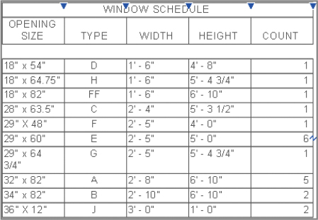
FIGURE 12.8 The Window schedule
Creating a Room Schedule
Creating other schedule types is fairly simple if you follow the guidelines just covered and step through the tabs in the Schedule Properties dialog box. You have one schedule under your belt, so let’s try another — this time, you’ll create a room schedule. Let’s try a different method for starting a new schedule. In the Project Browser, right-click Schedules/Quantities, select New Schedule/Quantities, and then follow these steps:
- Number
- Name
- Floor Finish
- North Wall
- East Wall
- South Wall
- West Wall
- Area
- Comments
FIGURE 12.9 Room schedule
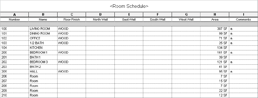
Notice that some of the fields already contain data. This is because some of this information was generated automatically (such as room areas), and some of it was added earlier in the process by adding room numbers to the plans or room names. Remember, schedules are just a tabular way of viewing the model — changes to the schedule will alter what you see in the model.
Now you’ll do something slightly different with this schedule. Because four of the columns are dealing with wall finishes, you’ll add a header to those columns so you can group them under one header.
FIGURE 12.10 Selecting the wall finishes
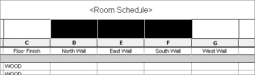
FIGURE 12.11 The room schedule

Creating a Sheet List
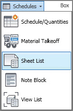
The last kind of schedule type we’ll talk about is a sheet list, which allows you to create a customized list of drawing sheets in your project and place it on a sheet for printing. This can be especially useful on larger projects where the sheet list can get long. This tool is also located on the Create panel of the View tab in the Schedules flyout.
This schedule has a feature that allows you to create placeholders for sheets that are not yet created or will not be part of your discipline’s drawings. You can use this feature to create full-sheet schedules including all consultant drawings. It also lets you create placeholder entries in the sheet schedule before you’ve created your own sheets.
In the sample workflow, you have created several sheets, and you now need to add a sheet list to your drawings.
FIGURE 12.12 Creating the sheet list
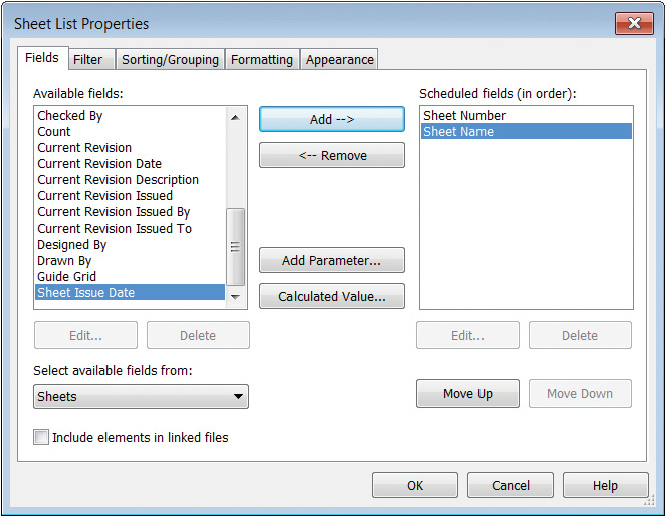
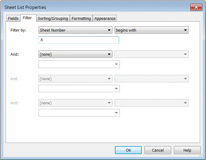
FIGURE 12.13 Creating a filter for specific sheets
- Create new sheets by using the View tab in the ribbon or by right-clicking the Sheets heading in the Project Browser.

- Add sheets by adding rows to a sheet list. These become placeholders until you create an actual sheet in your project. If you have placeholders in a sheet list, when you create a new sheet, you can select a placeholder from the New Sheet dialog box.
FIGURE 12.14 Adding sheets using a placeholder
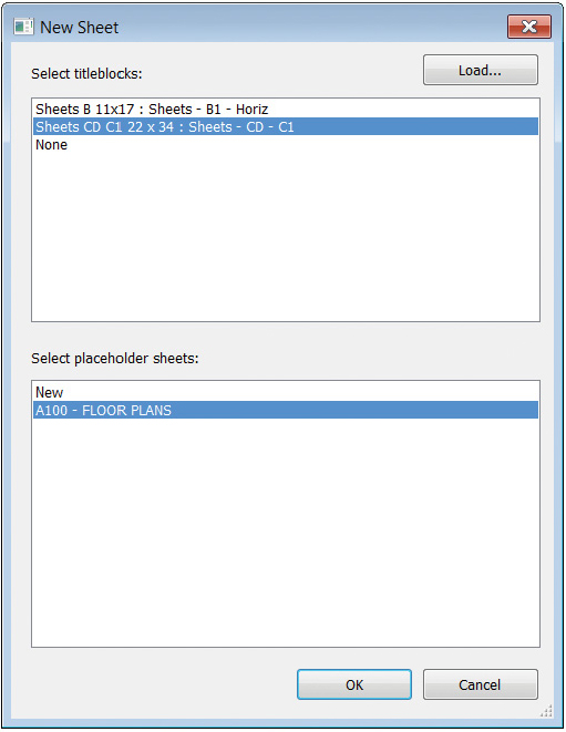
You’ll notice in the new sheet that the sheet number and sheet name have been automatically populated based on the information you added to the sheet list as a placeholder. This workflow is useful for larger projects where the index of drawings may be planned in advance and entered into a sheet list. As the design progresses and sheets are created, the design team only needs to pick from the list of placeholders. Also, remember that additional parameters can be added to the sheet list in addition to the number and name.
Placing Views on Sheets
Throughout this book, you have created several different kinds of views, from plans to elevations to perspectives. Eventually, you will need to lay out those views on sheets so they can be printed or converted to PDF and sent to clients or team members for review.
Creating sheets in Revit Architecture is very easy. As you’ve already seen, they can be created through a sheet list schedule. You can also create sheets by right-clicking the Sheet node in the Project Browser and selecting New Sheet from the context menu. Regardless of which method you use to create them, let’s walk through laying out these views on sheets and see how each view can be further manipulated once it’s placed on a sheet.
Adding Floor Plans to the Sheet
Because a series of views has already been created in the exercise file, let’s use the sheet you just made for placing some views. You place a view on a sheet by dragging the view out of the Project Browser and placing it on the sheet. Let’s practice this with another exercise.
FIGURE 12.15 Placing the view on a sheet
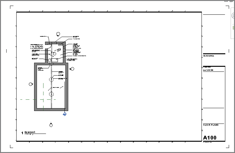
FIGURE 12.16 Aligning views on a sheet
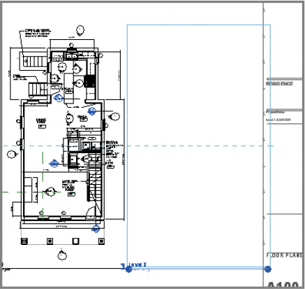
FIGURE 12.17 All the views placed on the sheet
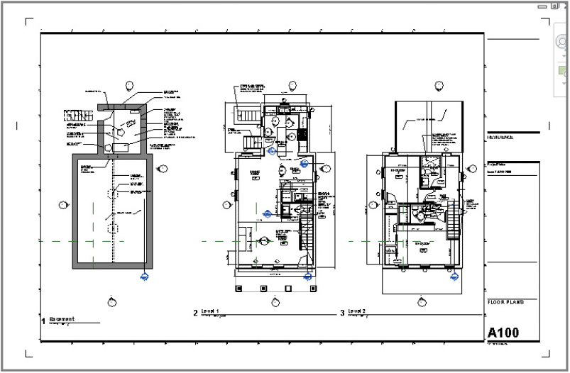
Once the views are placed on a sheet, you’ll inevitably want to do a bit of cleanup to the drawings to place everything properly. First, the view tag is placed in roughly the same place for each view; however, the default location might not be the location you desire. Revit Architecture also numbers the views sequentially (1, 2, 3, . . .) in order of placement.
Let’s adjust the view tags on the sheets. To adjust the text in the tags, start by selecting the view itself, not the tag.
FIGURE 12.18 The edited view tag
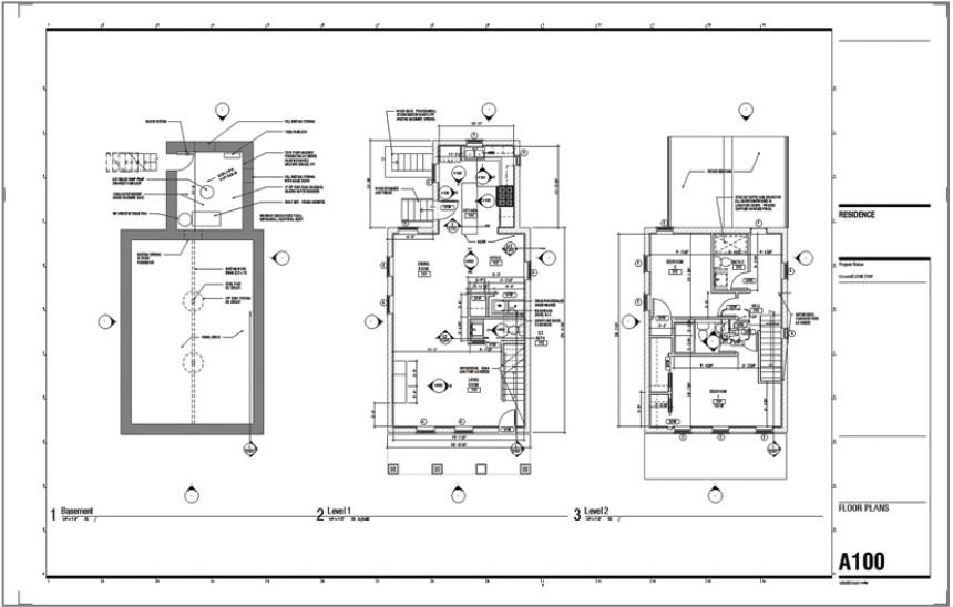
FIGURE 12.19 Moving the view tag

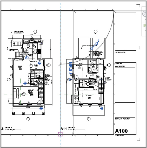
FIGURE 12.20 Laying out the rest of the sheet views
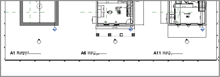
FIGURE 12.21 Adding lines to the sheet
With these dividing lines in place, you may notice that one of the text annotations in the Basement view is a little too close to the dividing line you added to the sheet (Figure 12.22). Let’s adjust it.
FIGURE 12.22 Text to be adjusted in the sheet view
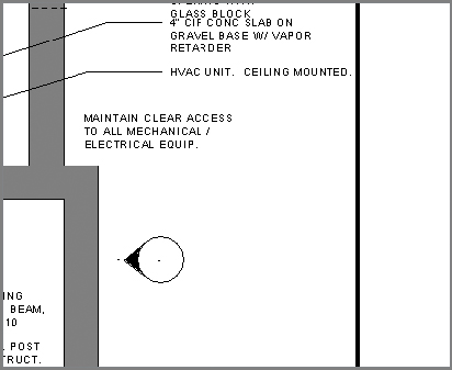
To adjust the text object on the floor plan view, you could simply open the view and adjust the text box, but you wouldn’t have the sheet and the dividing line as a reference. Instead, you’re going to use a command called Activate View.
Activating a view is like working in a model-space viewport while in paper space using the Autodesk® AutoCAD® software. You’re working on the actual view, but you’re doing so while it is placed on the sheet. This approach allows you the benefit of seeing how changes to the view affect the layout of the view on the sheet.
FIGURE 12.23 Activating the view
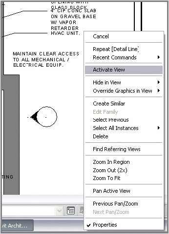
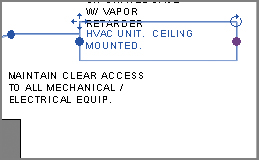
FIGURE 12.24 Modifying the text box
Adding the Schedules
With your sheet of floor plans configured and ready to print, you can quickly finish the sheet set by adding the window schedule you created earlier. Adding a schedule is just like adding any other view — you drag and drop it from the Project Browser onto the sheet.
Once the schedules are on the sheet, they may need a bit of adjustment. You can redefine the column spacing and even split larger schedules directly on the sheet to make them easier to read. Such adjustments do not change the actual schedule — just its appearance on the sheet.
To adjust a schedule placed on a sheet, highlight the schedule by selecting it. The schedule turns blue, and a few new grips appear that you can use to make changes (Figure 12.25). The blue inverted triangles at the top of each column allow you to modify the column widths. Grab one, and drag it left or right to change the column sizing.
FIGURE 12.25 Modifying the schedule on the sheet
You’ll also notice a blue cut symbol to the far right of a selected schedule. This cut symbol lets you break the schedule into two parts that can be placed on the same sheet. This can be especially handy if you have a long schedule, such as a room or door schedule, that has too many rows to fit on your sheet vertically. Selecting this tool breaks the schedule in half (and you can break it in half again and again) so you can take advantage of the horizontal real estate on your sheet. If you choose to separate your schedule in this fashion, it retains all the necessary information, and all the portions continue to automatically fill themselves dynamically as a single schedule would. You can also change the overall height of the schedule once it is broken by grabbing the grips at the bottom of the schedule and dragging them up or down.
With your schedule on the sheet and the columns properly formatted, you can drag the schedule around on the sheet until it’s located where you’d like to have it. To do so, click the schedule and hold down the left mouse button. As you move the schedule on the sheet, it behaves like other views: it aligns with the other schedules on the sheet and displays a light blue dashed line to help with alignment. Your finished sheet should look like Figure 12.26.
FIGURE 12.26 The finished cover sheet

Printing Documents
You will eventually need to get the sheets out of Revit Architecture and into a printed format. If you’ve been working in the Windows environment, you’ll find that printing from Revit Architecture is straightforward because the process resembles that used in other Windows-based applications.
Exploring the Print Dialog Box
To begin printing, you do not need to be in any particular view or sheet. Select the Application menu and then select Print ![]() Print to open the dialog box shown in Figure 12.27. All the features for printing are found here. Let’s step through this dialog box and explore each element.
Print to open the dialog box shown in Figure 12.27. All the features for printing are found here. Let’s step through this dialog box and explore each element.
FIGURE 12.27 Print dialog box
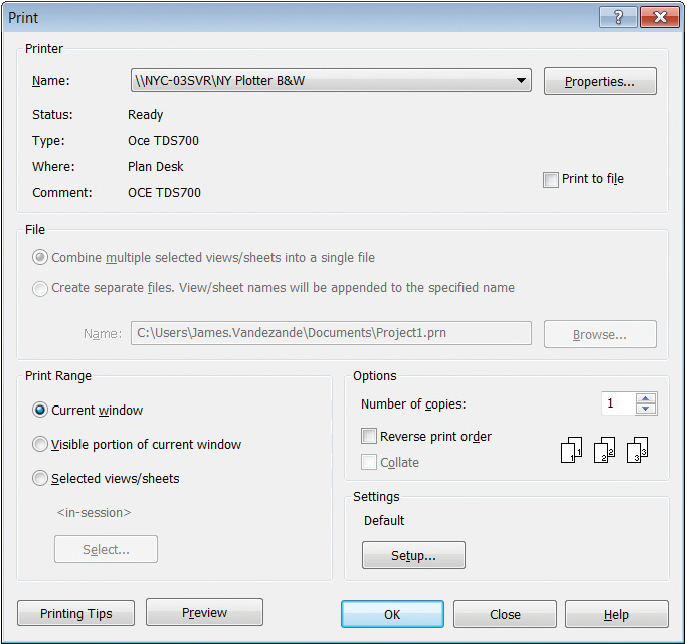
The drop-down menu at the top of the Print dialog box allows you to select the printer or plotter to which you want to print. This can be a physical printer or a virtual one (such as Adobe Acrobat Distiller). You can add printers to this list using your Windows Printer control panel.
Most of the controls you need to use can be found at the bottom of this dialog box in the Settings section on the right and the Print Range section on the left.
Exploring the Print Settings
In the Print dialog box, click the Setup button under Settings to open the Print Setup dialog box (Figure 12.28). Here you can customize the print settings including paper size, zoom, and orientation. You can save these settings with a name so that you can reuse them in later work sessions. We recommend creating saved setups based on a printer type — not for one specific printer. For example, if your office has several plotters of the same make and model, it is sufficient to create one setup named Full Size B/W Plot.
FIGURE 12.28 The Print Setup dialog box
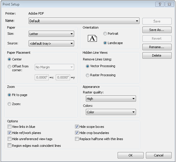
The print settings can also be transferred to other project files if necessary, using the Transfer Project Standards tool located on the Manage tab in the ribbon. Let’s take a look at some of the important printing options available to you.
Hidden Line Views
Views in Revit Architecture can be displayed in several graphic modes: Wireframe, Hidden Line, Shaded, Consistent Colors, and Realistic. The most commonly used type is Hidden Line. You’ll choose this mode for most floor plans, sections, and elevations, and sometimes even for 3D.
You have the option to print this type of view with vector processing or raster processing of the hidden lines. Vector is faster; however, you need to be aware of some nuances when working with hidden-line views. For example, transparent materials (such as glass) print transparent with raster processing but opaque with vector processing.
Zoom
If you’re looking for the ability to print a view to a specific scale (the way you would in the Autodesk AutoCAD software), it’s actually much simpler in Revit Architecture. Remember that every view is assigned a scale factor; therefore, printing a view is always determined as a percentage of that assigned scale. For example, if a floor plan is assigned a scale factor of 1/4″=1’-0″ (1:50) and you would like to generate a quick print of the plan at 1/8″=1’-0″ (1:100), simply set the zoom to 50 percent. Sheets should be printed at 100 percent for full-size or 50 percent for a half-size set.
Options
The Options pane is at the bottom of the Print Setup dialog box. The pane includes these options:
When all your options are set, you can save the settings so you can reuse them on future prints. Because everyone’s system printer configurations will be somewhat different, we won’t ask you to create a specific setting configuration. Instead, use the information we just reviewed to create your own printer setup configuration. Note that you can change settings temporarily by selecting the <in-session> setting from the Name drop-down. Then, click OK to close this dialog and return to the Print dialog.
Exploring the Print Range
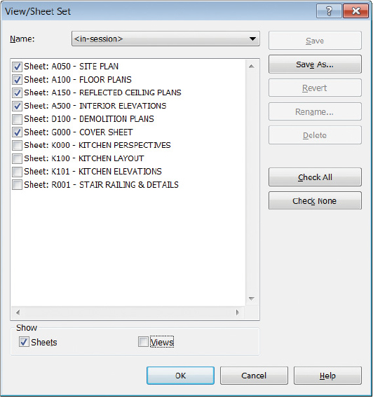
The other important part of the Print dialog box is Print Range. In this section, you can define exactly what areas, sheets, or views you want to print. It includes these options:
You can pick any view or sheet to include in the view/sheet set. If you want to include only sheets in a set, use the Show options at the bottom of the View/Sheet Set dialog box to shorten the visible list. Doing so allows you to select only sheets or only views if you choose.
This is a great tool to help define print lists. Some examples of using these selections would be a 100 percent construction document package or a specific set of presentation sheets.
In the exercise, suppose you want to print the A-series sheets and the G000 cover sheet. Follow these steps:
FIGURE 12.29 Selecting the desired sheets
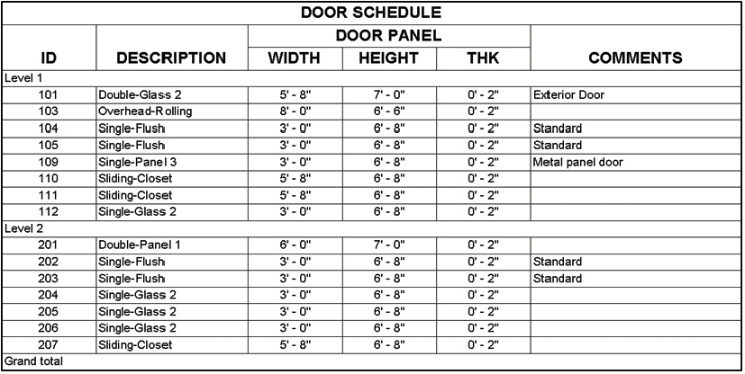
- Create a door schedule, and add the following fields:
- Lay out this new schedule on sheet G000; be sure to align it with the schedules you already placed on that sheet. Change the schedule’s Sorting/Grouping options by including the Count field and toggling the Itemize Every Instance setting. Observe the differences in scheduling every door compared to a rolled-up schedule showing only individual door types and how many of each exist in the project.