Chapter 5
Node Level Routing Mechanisms
5.1 Introduction
Following the previous chapter, where the notion of function level relaying techniques was analysed, starting with the developments related to both conventional relaying and cooperative relaying, advanced with the rationale behind the related fixed deployment concepts, to eventually prepare the ground for the introduction of approaches compliant with the mobile deployment concept, orchestrated by the Autonomic Cooperative Behaviour, the time has come to progress further with the node level routing mechanisms. The description is opened with the pertinent workings of the Optimised Link State Routing protocol, where special emphasis is laid on the experimentation-related version thereof. First, the functional and structural characteristics are analysed in more detail, translating generally into the field of applicability and the assumed messaging structure. Not only is the proactivity of the Optimised Link State Routing protocol underlined as being highly relevant to the mobile ad hoc network scenarios that are predominantly of interest, but its inherent multi-point relay station selection heuristics is presented, incorporating certain small alignments in light of its pivotal role in the concept of the Autonomic Intelligence Evolved Cooperative Networking. Additionally, the information storage repositories are scrutinised to provide the necessary context for further developments, and to introduce new elements such as the virtual antenna array selector set and its related virtual antenna array selector tuples, so necessary to advance the plot to encompass routing information enhanced cooperative transmission.
Then follow developments stemming from the routing information enhanced algorithm for cooperative transmission, originally devised by the author as a method for exploiting the additional data collected at the network layer by the Optimised Link State Routing protocol, and its accordingly modified version in particular, for the sake of not only enabling, but also orchestrating the said cooperative transmission at the link layer. For this reason the justification for the introduction of the routing information enhanced algorithm for cooperative transmission is provided, with special emphasis on its algorithmic description, which incorporates certain elements and nomenclature of the Optimised Link State Routing protocol, mostly due to the direct usage of the outcome of the multi-point relay station selection heuristics. The reliance of the routing information enhanced algorithm for cooperative transmission on the multi-point relay station selection heuristics is key in this respect, as these multi-point relays are to form the virtual antenna arrays intended to instantiate the distributed space-time block coding over the virtual multiple-input multiple-output radio channel. Then, as a more accurate concept in the form of the extended routing information enhanced algorithm for cooperative transmission is outlined, which will lead directly to the Autonomic Cooperative Networking Protocol, the evolved messaging structure is presented with appropriate commentary. Last, but not least, both the critical issues of address auto-configuration and duplicate address detection are analysed on the basis of certain externally proposed solutions.
The focus then shifts towards the ultimate function level overlay logic intended to allow the fusion of all the technological advancements presented thus far under the umbrella of the entities inherent in the Autonomic Cooperative Networking Architectural Model. In particular, the description starts with the aforementioned Autonomic Cooperative Networking Protocol: the reasoning for the prior introduction of its source extended routing information enhanced algorithm for cooperative transmission is provided, with all the updates necessary to ensure proper transition and integration, as well as the justification of the role and importance of the evolved messaging structure in the process of Autonomic Cooperative Node preselection is given, along with the rationale behind the specifically designed routing table. In the light of the above, an extended algorithmic description of the logic governing the cooperation management decision element is presented with reference to the previous analysis of the original routing information enhanced algorithm for cooperative transmission, so that it is not only possible to evaluate the advantages thereof with the aid of simulation analysis, but also to perform further investigations into the overhead aspects of the above-mentioned evolved messaging structure. As usual, the chapter is concluded with the architectural integration aspects, where, initially, the roots of the Autonomic Cooperative Networking Protocol are discussed, complemented with an overview of certain pertinent conceptual transitions, so that more complex dependencies among the routines and their architectural relations can be scrutinised.
5.2 Optimised Link State Routing Protocol
5.2.1 Functional and Structural Characteristics
In this book the emphasis is laid on the original version of the Optimised Link State Routing (OLSR) protocol, ‘left in place for further experimentation’1 (Clausen et al., 2014). In particular, it is the multi-point relay (MPR) station selection heuristics, aimed at reducing the control overhead (understood as the number of control messages broadcast to disseminate network topology information), that is to be of special interest for cooperative transmission integration. In general, this idea consists in the transmission of the so-called topology control (TC) messages with the aid of exclusive sets of carefully selected neighbour nodes, which not only belong to the one-hop neighbourhood of a given network node, but are able to jointly cover the entire strict two-hop neighbourhood of the same, as outlined by Qayyum et al. (2002). Such one-hop network nodes are recognised with Hello messages, which are received by each of them, but never directly retransmitted any further. These messages are generated on the basis of the information stored in the local link set, neighbour set, and multi-point relay set, as defined by Clausen and Jacquet (2003). The broadcasting of Hello messages takes place in a periodic manner by every active network node over all the interfaces thereof for the sake of link sensing, which is indispensable for detecting the existence of a radio link.2 Given this context, once the functional routing classes have been presented, the structural aspects of both the Optimised Link State Routing protocol packet and its inherent Hello message are described so that, following encapsulation, they may be conveyed with the aid of the User Datagram Protocol (UDP).
As proposed originally by Clausen and Jacquet (2003) and then expanded by Clausen et al. (2014), the Optimised Link State Routing protocol is targeted at mobile ad hoc networks.3 Since such environments are typically characterised by very dynamic fluctuations in terms of a continually changing network topology, the protocol should be tailored accordingly so that, keeping the control overhead at a reasonable level, it is still possible to follow any changes and provide accurate routing information, as summarised by Wódczak (2012a). Most generally, one may distinguish between three major routing classes4 attributable to mobile ad hoc network environments,5 as outlined by Abolhasan et al. (2005). First of all, there is the proactive class, where each network node performs topology recognition on a regular basis, so that routing tables (RTBs) are always up to date. Unfortunately, unless optimised, such an approach could be costly in terms of the above-mentioned control overhead – frequently referred to as protocol overhead. Then one may distinguish the reactive class where topology recognition is performed once the routing tables need to be updated, which reduces the overhead, but unfortunately increases the routing path selection delay. Last, but not least, there is the hybrid class, being a combination of the advantages of the previous two methods, taking into account the activity of mobile nodes (MNs) in specific regions of the network. As long as the topology changes can be classified as insignificant the reactive mode should most naturally prevail, while, should the opposite hold true, the proactive one would apply.
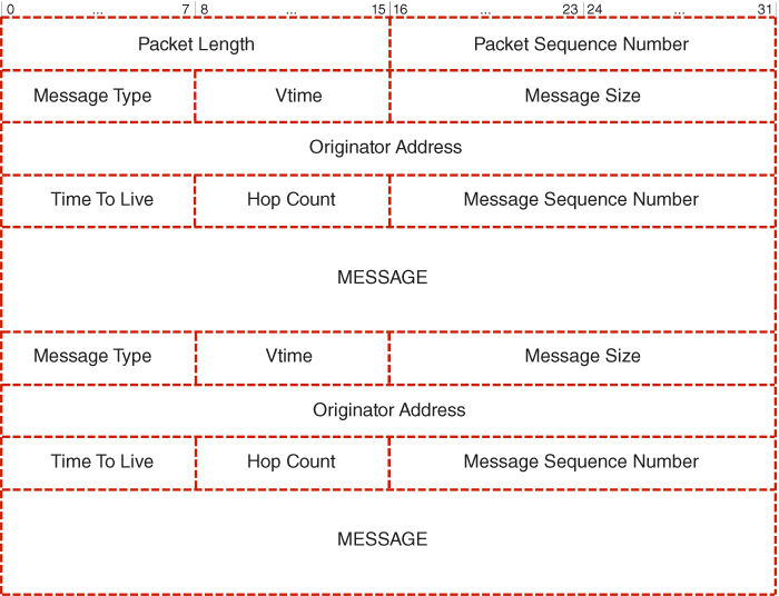
Figure 5.1 OLSR packet. Adapted from Clausen and Jacquet (2003).
Moving forward, the Hello messages allow each MN to discover its entire one-hop neighbourhood and to identify its overall two-hop neighbourhood, while the information gathered becomes directly exploitable by the multi-point relay station selection heuristics. In order to provide sufficient context for further introduction of the relevant extensions to the protocol in question, the packet format will be described along with the format of the Hello message it normally encapsulates, as originally introduced by Clausen and Jacquet (2003). In fact, one should note that the aforementioned TC messages are encapsulated in similar protocol packets, but as their analysis appears to remain beyond the scope of this description, the reader is referred directly to the specification by Clausen and Jacquet (2003). Scrutinising the said packet format, as depicted in Figure 5.1, one should discern immediately that its structure always opens with the Packet Length field of 16 bits which specifies the packet length in bytes. It is followed by the Packet Sequence Number field of 16 bits which is incremented each time a new packet is transmitted. Then, distinct messages are included, preceded by a header composed of a number of relevant fields. First of all, there is the Message Type of 8 bits which not only indicates the type of the carried message, but also accommodates sufficient amount of space to make any future attempts at defining new message types possible. Second is the Vtime field of 8 bits, also known as Validity time, which defines for how long the received data shall be considered valid in the absence of further updates, and is represented by mantissa a and exponent b values.
These values are contained in the four most significant bits (MSBs) and the four least significant bits (LSBs) of the Vtime field, respectively, and the resulting Validity time is calculated according to the following formula:
where C is a constant scaling factor which, according to Clausen and Jacquet (2003), is assumed to be equal to
Next is the Message Size field of 16 bits containing the size of the message in bytes, as counted from the beginning of the Message Size field to the beginning of the next Message Size field, or the end of the entire Optimised Link State Routing protocol packet if there are no more messages. What follows is the Originator Address field of 32 bits containing the main address of the network node which originally issued this message. According to Clausen and Jacquet (2003), it is crucial to note that this address does not correspond to the Source Address of the Internet Protocol (IP) header, which changes each time to the address of the intermediate retransmitting interface. Then, there is the Time To Live (TTL) field of 8 bits, indicating the maximum number of hops over which a given message may be retransmitted. It is decremented by 1 before a retransmission, and a message must not be retransmitted should its TTL become equal to 0 or 1. Moving forward, there are the Hop Count field of 8 bits which contains the number of hops a given packet has traversed so far and the Message Sequence Number field of 16 bits which contains a unique identification number to ensure that a specific message is transmitted only once.
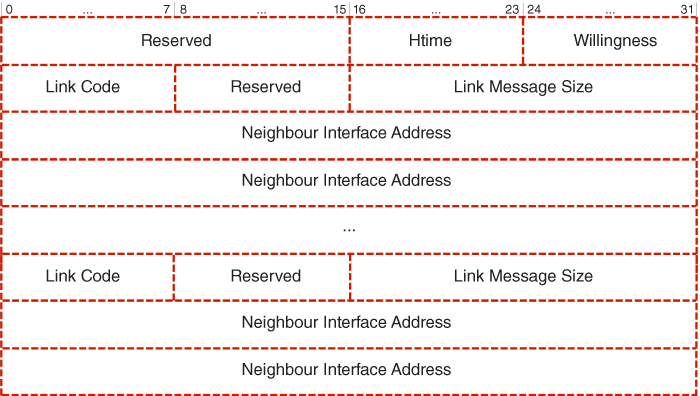
Figure 5.2 Hello message. Adapted from Clausen and Jacquet (2003).
The final component in the form of the MESSAGE field has a variable size and carries the relevant contents, such as the Hello message. According to Figure 5.2, Hello messages also comprise a number of important fields (Clausen and Jacquet, 2003). First, there is the Reserved field of 16 bits that must be set to 0000000000000000.6 This is followed by the Htime field of 8 bits, also known as the Holding time, which is used to specify the Hello message emission interval over a given interface. Such an interval is similarly represented in the form of a mantissa a, the four MSBs, and an exponent b, the four LSBs. Consequently, the emission interval can be calculated according to the following formula:
where C is the constant scaling factor defined in Equation 5.2. Although the predefined Hello message emission interval is 2 s, it can range from 62.6 ms up to almost 2.28 hr. Next, there is the Willingness field of 8 bits specifying whether a given network node is willing to carry and forward traffic or not. There are the following levels of willingness: WILL_NEVER (0), WILL_LOW (1), WILL_DEFAULT (3), WILL_HIGH (6), and WILL_ALWAYS (7). One should note that for a Willingness of 0 or 7 a given network node must never or must always be selected as a multi-point relay, respectively. Then comes the Link Code of 8 bits defining the type of the link between an interface of a given network node and the listed interfaces of its neighbours, as well as the Neighbour Type. Last is the Neighbour Interface Address of 16 bits, denoting the interface address of a given neighbour node.
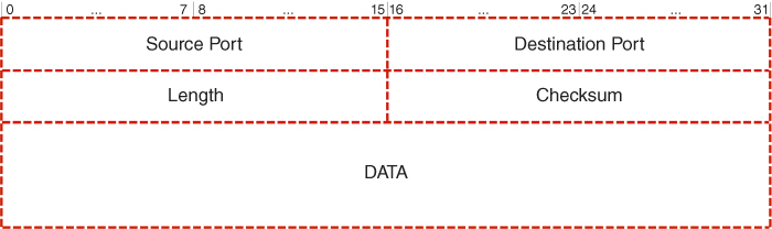
Figure 5.3 UDP datagram. Adapted from Postel (1980).
Given the above, it transpires that, due to a unified packet format, not only is the Optimised Link State Routing protocol easily extensible, but its packets normally undergo further encapsulation with the use of the User Datagram Protocol (UDP), as defined by Postel (1980), before transmission over the network. For reference reasons, the format of a UDP datagram is outlined in Figure 5.3. Its structure begins with the Source Port field of 16 bits which is optional, yet when exploited indicates the port of the sending process in case such information is useful. If it is not specified a zero value is used; otherwise, this is the port to which a reply shall be sent should any other information be missing. Then comes the Destination Port field of 16 bits indicating the port of the destination process to which the datagram is to be delivered. Next comes the Length field of 16 bits which specifies the length of the datagram in octets including both the header and the data sections. Consequently, the minimum value of this field is 8. Then there is the Checksum field of 16 bits containing the checksum of the so-called pseudo-header, which is composed of the IP header, the UDP header, and the DATA field, padded with zero octets at the end, as described by Postel (1980). Last, but not least, is the DATA field of variable size which contains the data octets in the form of, for instance, the Hello messages described above, encapsulated into packets of the Optimised Link State Routing protocol, which was assigned the exclusive port number of 698 by the Internet Assigned Number Authority (IANA).
5.2.2 Multi-Point Relay Station Selection Heuristics
One of the main advantages of the Optimised Link State Routing protocol is related to its inherent ability to utilise a set of preselected network nodes for the purposes of control data dissemination. Such network nodes, known as multi-point relays, are identified by a given source node on the basis of an analysis of its entire symmetric one-hop and two-hop neighbourhoods. In fact, even though all the neighbour nodes located within range of such a source node are always entitled to receive and process the control messages it may broadcast, given the obvious nature of the wireless transmission medium, they are not allowed to retransmit those messages any further unless they have been included in the MPR set. In other words, this approach aims to minimise the amount of redundantly retransmitted control data, so that the overall protocol overhead may be reduced, if not optimised. In order to perform the relevant multi-point relay station selection heuristics, a given source node, denoted as ![]() , needs to acquire all the pertinent information related to its one-hop and two-hop neighbourhoods. Since the aforementioned Hello messages are periodically emitted by each one-hop neighbour node
, needs to acquire all the pertinent information related to its one-hop and two-hop neighbourhoods. Since the aforementioned Hello messages are periodically emitted by each one-hop neighbour node ![]() , and they also include the statuses of the corresponding links, the source node may identify both its one-hop and two-hop symmetric neighbourhoods. Given the above, an optimised algorithmic description of the multi-point relay station selection heuristics is provided below, and the relevant neighbourhood types are classified for reference reasons. Finally, the distinction between routing and flooding multi-point relays is outlined, as defined by Clausen et al. (2014).
, and they also include the statuses of the corresponding links, the source node may identify both its one-hop and two-hop symmetric neighbourhoods. Given the above, an optimised algorithmic description of the multi-point relay station selection heuristics is provided below, and the relevant neighbourhood types are classified for reference reasons. Finally, the distinction between routing and flooding multi-point relays is outlined, as defined by Clausen et al. (2014).
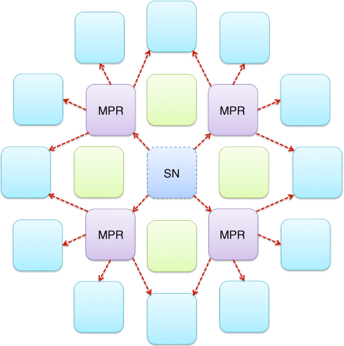
Figure 5.4 Multi-point relay station selection heuristics. Adapted from Qayyum et al. (2002).
Before the multi-point relay station selection heuristics,7 as depicted in Figure 5.4, is described, it is necessary to introduce the notation to be used. ![]() and
and ![]() refer to the sets of one-hop and two-hop neighbour nodes of a given source node, respectively. Similarly,
refer to the sets of one-hop and two-hop neighbour nodes of a given source node, respectively. Similarly, ![]() represents the multi-point relays of that source node, where a multi-point relay is understood as a one-hop neighbour node selected by source node
represents the multi-point relays of that source node, where a multi-point relay is understood as a one-hop neighbour node selected by source node ![]() to retransmit all the broadcast messages received from
to retransmit all the broadcast messages received from ![]() on condition that, since a retransmitted message cannot be a duplicate, its TTL field must carry a value greater that one (Clausen and Jacquet, 2003). In general, the multi-point relay station selection heuristics is carried out with the aid of both sets of one-hop and two-hop neighbour nodes. For the sake of clarity, one needs to additionally assume that both the sets
on condition that, since a retransmitted message cannot be a duplicate, its TTL field must carry a value greater that one (Clausen and Jacquet, 2003). In general, the multi-point relay station selection heuristics is carried out with the aid of both sets of one-hop and two-hop neighbour nodes. For the sake of clarity, one needs to additionally assume that both the sets ![]() and
and ![]() are formed only of symmetric network nodes that are reachable via bidirectional links, as described in Table 5.1. According to the specification by Clausen and Jacquet (2003), the multi-point relay station selection heuristics is launched by source node
are formed only of symmetric network nodes that are reachable via bidirectional links, as described in Table 5.1. According to the specification by Clausen and Jacquet (2003), the multi-point relay station selection heuristics is launched by source node ![]() when the set
when the set ![]() contains all the members belonging to the one-hop neighbourhood
contains all the members belonging to the one-hop neighbourhood ![]() that are always willing to carry and forward traffic. The author additionally assumes that those network nodes are no longer included in the set
that are always willing to carry and forward traffic. The author additionally assumes that those network nodes are no longer included in the set ![]() , and that the degree of each network node
, and that the degree of each network node ![]() in
in ![]() has been computed, where the degree of a symmetric one-hop neighbour node is defined as the number of its symmetric neighbour nodes, excluding all the members of
has been computed, where the degree of a symmetric one-hop neighbour node is defined as the number of its symmetric neighbour nodes, excluding all the members of ![]() and the source node
and the source node ![]() itself (Wódczak, 2006).
itself (Wódczak, 2006).
Table 5.1 Neighbourhood type characteristics
| Neighbourhood type | Characteristics |
| Symmetric one-hop neighbourhood | A set of network nodes which have at least one symmetric link to the source node. |
| Symmetric two-hop neighbourhood | A set of network nodes, excluding the source node, which have symmetric links to the symmetric one-hop neighbour nodes of that source node. |
| Strict symmetric two-hop neighbourhood | A set of network nodes, excluding the source node and its neighbour nodes, which have a symmetric link to a symmetric one-hop neighbour node of that source node, characterised by a willingness level different from WILL_NEVER. |
Examining Algorithm 5.1, adapted by the author from Clausen and Jacquet (2003), the source node ![]() chooses, using the
chooses, using the ![]() function, those network nodes from its one-hop neighbourhood
function, those network nodes from its one-hop neighbourhood ![]() that are the only ones to provide reachability to a network node
that are the only ones to provide reachability to a network node ![]() in the strict symmetric two-hop neighbourhood
in the strict symmetric two-hop neighbourhood ![]() . However, in contrast to the specification, network nodes of zero reachability are removed from the set
. However, in contrast to the specification, network nodes of zero reachability are removed from the set ![]() . Thus, only the network nodes characterised by a reachability higher than one may remain in the set
. Thus, only the network nodes characterised by a reachability higher than one may remain in the set ![]() , to simplify the algorithmic description. Then, until there exist uncovered network nodes in
, to simplify the algorithmic description. Then, until there exist uncovered network nodes in ![]() , the algorithm keeps selecting the network node in
, the algorithm keeps selecting the network node in ![]() that has the highest willingness to carry and forward traffic. This operation is performed with the aid of the
that has the highest willingness to carry and forward traffic. This operation is performed with the aid of the ![]() function, and the results are stored in the set
function, and the results are stored in the set ![]() . In the case of multiple possibilities, i.e. when
. In the case of multiple possibilities, i.e. when ![]() , the candidate is selected through which the highest number of still uncovered nodes in
, the candidate is selected through which the highest number of still uncovered nodes in ![]() can be reached. To this end the
can be reached. To this end the ![]() function is used, which results in the set
function is used, which results in the set ![]() . If it is still impossible to select one network node only, i.e.
. If it is still impossible to select one network node only, i.e. ![]() , the network node of the highest degree is chosen using the function
, the network node of the highest degree is chosen using the function ![]() . If the problem of multiple choice arises again, i.e.
. If the problem of multiple choice arises again, i.e. ![]() , the author proposes picking one of them at random using the function
, the author proposes picking one of them at random using the function ![]() . One should note that each time a network node
. One should note that each time a network node ![]() , which covers a network node
, which covers a network node ![]() , is included in the MPR set, the network node
, is included in the MPR set, the network node ![]() is removed from the set
is removed from the set ![]() . Eventually, the network node
. Eventually, the network node ![]() is removed from the set
is removed from the set ![]() , accordingly.8
, accordingly.8
Lastly, one should note that, unlike Clausen and Jacquet (2003), the latest version of the specification describing the Optimised Link State Routing protocol provides a new notion of routing multi-point relay (RMPR) stations, as opposed to the legacy ones, currently directly referred to as flooding multi-point relay (FMPR) stations (Clausen et al., 2014). Essentially, even though, at least at first sight, such a distinction would seem negligible, in fact there appears to be much more to it from the structural and functional perspectives.9 In particular, looking at the legacy version of the Optimised Link State Routing protocol, the predominant role of the multi-point relay stations was to be ‘responsible for forwarding control traffic, intended for diffusion into the entire network’ (Clausen and Jacquet, 2003). Most obviously, the capability of multi-point relays was also exploited to provide routing enhancements, yet this was not so much exposed as it is now. In fact, looking at Clausen et al. (2014), one may easily discern that much more emphasis is laid on the routing part, as currently the protocol incorporates the exploitation of additive link metrics different from the previously allowed hop count. There is then no wonder that the FMPRs were given a proper name, while the RMPRs were defined to reflect certain characteristics. In essence, following what was specified by Clausen et al. (2014), on the one hand, while the former need not use any metrics at all, it becomes obligatory for the latter, yet, on the other hand, also quite reasonably, as the former are bound to an interface, the latter are by no means restricted in this respect.
5.2.3 Information Storage Repositories
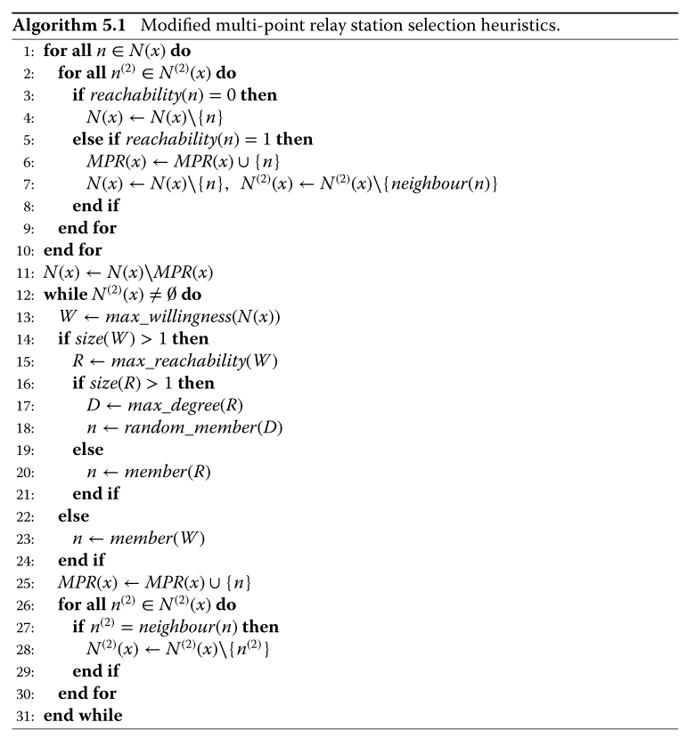
The Optimised Link State Routing protocol acquires various pieces of information by means of link sensing, neighbour detection, multi-point relay station selection, or topology discovery. Consequently, it is bound to maintain certain information repositories; these will be characterised in this section to prepare for the introduction of the virtual antenna array (VAA) selector tuple which, among other modifications, is to be instrumental in outlining the evolved version of the routing information enhanced algorithm for cooperative transmission (REACT) (Wódczak, 2014a). In fact, examining the repositories in question, one may provide the general classification depicted in Figure 5.5, where four major categories are included: Multiple Interface Association Information Base, Local Link Information Base, Neighbourhood Information Base, and Topology Information Base. Interesting though it may seem, the most recent version of the Optimised Link State Routing protocol, as defined by Clausen et al. (2014), exploits a related, yet modified, group of repositories in the form of the Local Information Base, Interface Information Base,10 and Neighbour Information Base. Given the fact that the experimentation-targeted version of the Optimised Link State Routing protocol is to be scrutinised in this chapter, any more detailed comparison with its most recent incarnation remains beyond the scope of this book. The four categories will be addressed by the presentation, in turn, of the interface association tuple, the link tuple, the neighbour tuple, two-hop neighbour tuple, MPR selector set, and the VAA selector tuple, to conclude with the topology tuple.
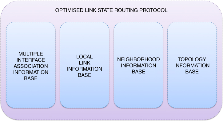
Figure 5.5 OLSR protocol repositories.
Table 5.2 Interface association tuple. Adapted from Clausen and Jacquet (2003)
| Item | Description |
| I_iface_addr | Specifies the address of the interface of a given destination node. |
| I_main_addr | Specifies the main address of a given destination node. |
| I_time | Specifies the expiry time at which this tuple will be discarded. |
Table 5.3 Link tuple. Adapted from Clausen and Jacquet (2003)
| Item | Description |
| L_local_iface_addr | Specifies the address of the interface of a given local network node. |
| L_neighbor_iface_addr | Specifies the address of the interface of a given neighbour node. |
| L_SYM_time | Specifies the time until which a given link shall be considered symmetric. |
| L_ASYM_time | Specifies the time until which a given interface of a given neighbour node shall be considered heard. |
| L_time | Specifies the expiry time at which this tuple shall be discarded. |
In an effort to provide commentary on the relevant tuples11 adapted from Clausen and Jacquet (2003), first comes the Multiple Interface Association Information Base containing the interface association set. This set is composed of the so-called interface association tuples, which are stored for every destination node in the network. Such a tuple is composed of the items described in Table 5.2. Next comes the Local Link Information Base, which is related to the operation of link sensing and contains the related link set. This set is formed by the so-called link tuples comprising a number of items, as outlined in Table 5.3. Based on this information, the neighbour interfaces may be declared using Hello messages. One should note that once the L_SYM_time expires, the link shall be considered asymmetric; should both the L_SYM_time and L_ASYM_time expire, the link is considered lost. Then comes the Neighbour Information Base, which is related to the operation of neighbour detection and originally contains the neighbour set, two-hop neighbour set, as well as the related MPR set and MPR selector set, while the pertinent tuples are recorded for the latter only. In particular, these sets are formed by the main addresses of the neighbour nodes selected as multi-point relays along with the so-called neighbour tuples, two-hop tuples, and MPR selector tuples described in Tables 5.4, 5.5, and 5.6, respectively (Clausen and Jacquet, 2003). What is more, for the needs of the upcoming modifications, having processed the yet to be defined Modified Hello message, each neighbour node of (yet to be characterised) VAA_NEIGH type would need to store the acquired data with the aid of an additional VAA selector set.
Table 5.4 Neighbour tuple. Adapted from Clausen and Jacquet (2003)
| Item | Description |
| N_neighbor_main_addr | Specifies the main address of a given neighbour node. |
| N_status | Specifies whether a given neighbour node shall be considered as being connected over a symmetric or nonsymmetric link. |
| N_willingness | Specifies an integer value within the range 0 to 7 indicating whether a given neighbour node shall be willing to carry and forwarda traffic coming from other network nodes. |
a The specification does not explicitly mention forwarding, yet the author assumes that such a meaning is naturally implied in this respect.
Table 5.5 Two-hop neighbour tuple. Adapted from Clausen and Jacquet (2003)
| Item | Description |
| N_neighbor_main_addr | Specifies the main address of a given neighbour node. |
| N_2hop_addr | Specifies the main address of a given two-hop neighbour node connected to the one denoted by N_neighbor_main_addr with a symmetric link. |
| N_time | Specifies the expiry time at which this tuple shall be discarded. |
Table 5.6 MPR selector tuple. Adapted from Clausen and Jacquet (2003)
| Item | Description |
| MS_main_addr | Specifies the main address of the neighbour node which selected this specific network node as an MPR. |
| MS_time | Specifies the expiry time at which this tuple shall be discarded. |
Table 5.7 VAA selector tuple. Adapted from Wódczak (2014)
| Item | Description |
| VS_main_addr | Specifies the main address of the neighbour node which selected this network node as the element of a VAA. |
| VS_elem_id | Specifies the VAA element identification number indicating the column according to which the EDSTBE shall process the retransmitted signals. |
| VS_time | Specifies the expiry time at which this tuple shall be discarded. |
Table 5.8 Topology tuple. Adapted from Clausen and Jacquet (2003)
| Item | Description |
| T_dest_addr | Specifies the main address of the neighbour node which may be reached in one hop by the network node denoted by T_last_addr. |
| T_last_addr | Specifies the network node which typically is the MPR of the destination node denoted by T_dest_addr. |
| T_seq | Specifies the sequence number. |
| T_time | Specifies the expiry time at which this tuple shall be discarded. |
Such a VAA selector set, to be maintained in the Neighbour Information Base, as indicated by Wódczak (2014a), would be formed of VAA selector tuples following the format outlined in Table 5.7, so that each network node could determine whether it would be expected to cooperate after receiving a user data packet from any of its neighbours by simply comparing its address with the VS_main_addr. Should there be a match, then the relevant element of the virtual antenna array, also referred to as a VAA_NEIGH network node, would process the signals according to the appropriate column of the code matrix employed by the equivalent distributed space-time block encoder (EDSTBE), as specified by VS_elem_id. Finally, there is the Topology Information Base, which is related to the operation of topology discovery and contains the topology set. This set comprises the so-called topology tuples, which are composed of the items described in Table 5.8. All in all, comparing the structure of and relations between the information storage repositories of the original Optimised Link State Routing protocol with what is offered by its latest incarnation, one may come to the general conclusion that there are two dimensions to be considered. The most recent version of this protocol appears to promote a more consistent view by introducing a reduced number of repositories with a clear distinction between information defined locally and received globally. Moreover, in the experimentation-related version, a given repository or base may contain only a single set, but the latest update provides a much more balanced structure. Regardless of the above advantages, the experimentation track is followed in this book.
5.3 Routing Information Enhanced Cooperation
5.3.1 Justification and Algorithmic Outline
Given the background provided in the opening part of this chapter, where certain aspects of relevance for further description, inherently rooted in the Optimised Link State Routing protocol were described with additional commentary, the time has come to advance the analysis towards an evolved version of what was initially devised by the author under the name routing information enhanced algorithm for cooperative transmission (Wódczak, 2012a).12 As such, the original version of REACT was conceived with the aim of finding a solution that could not only orchestrate, but also enhance the typically link layer driven cooperative relaying based on virtual antenna arrays, where distributed space-time block coding would be instantiated among the network nodes preselected to cooperate. In particular, the observation was made that there is much in common between the multi-point relay station selection heuristics of the Optimised Link State Routing protocol and the manner in which virtual antenna arrays are formed. Then, certain design decisions were made with respect to the workings of the Optimised Link State Routing protocol in order to reuse the routing information readily available at the network layer to enhance the cooperative relaying at the link layer. In the light of the above, the common aspect between the multi-point relay station selection heuristics and the concept of virtual antenna arrays will be detailed, so that it is possible to elaborate on the algorithmic description before the focus shifts to the evolved messaging structure (Wódczak, 2014a).
Keeping in mind the importance of the applied nomenclature, one should note that, even though certain advancement in the naming structure was already indicated, including the notion of virtual antenna arrays to be elevated to the concept of autonomic cooperative sets (ACSs), the author decided that, for the sake of clarity, the original naming pattern employed for REACT should at this stage be generally followed, with additional commentary whenever applicable. This is especially important for the introduction of the common aspect between multi-point relays and virtual antenna arrays, since both of them are soon to be integrated with the concept of the Autonomic Cooperative Node (ACN). Nonetheless, shifting the viewpoint more towards the Optimised Link State Routing protocol itself, one may notice that its inherent mechanisms were designed to allow each of the network nodes to acquire virtually full knowledge about their one-hop and two-hop neighbourhoods. What is more, it is possible to identify the one-hop neighbour nodes in ![]() that can provide connectivity to certain two-hop neighbour nodes in
that can provide connectivity to certain two-hop neighbour nodes in ![]() . In fact, this is one of the major reasons why REACT was based on the multi-point relay station selection heuristics, since obviously there exists a common aspect between the two. Generally, only those network nodes are identified as multi-point relays that can provide connectivity to a two-hop neighbour node
. In fact, this is one of the major reasons why REACT was based on the multi-point relay station selection heuristics, since obviously there exists a common aspect between the two. Generally, only those network nodes are identified as multi-point relays that can provide connectivity to a two-hop neighbour node ![]() . As depicted in Figure 5.6, this assumption especially holds true for the network nodes to be preselected as the relay nodes intended to form a virtual antenna array.
. As depicted in Figure 5.6, this assumption especially holds true for the network nodes to be preselected as the relay nodes intended to form a virtual antenna array.
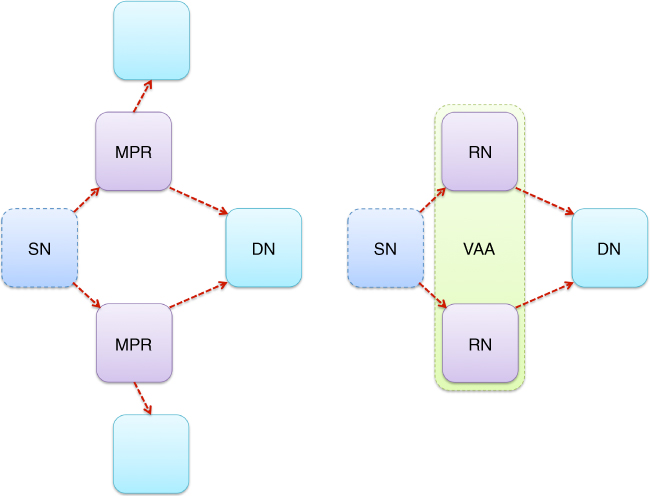
Figure 5.6 Common aspect of MPRs and VAAs.
Moving into the details, based on additional link state information provided by the Optimised Link State Routing protocol, the proposed solution attempts to assign multi-point relays to specific virtual antenna arrays, as outlined by Wódczak (2011c). For the sake of the analysis of Algorithm 5.2, one may recall that the sets ![]() and
and ![]() , containing solely symmetric neighbour nodes reachable over bidirectional links, are formed respectively by the one-hop neighbours and two-hop neighbours of the network node denoted as
, containing solely symmetric neighbour nodes reachable over bidirectional links, are formed respectively by the one-hop neighbours and two-hop neighbours of the network node denoted as ![]() . Moreover, the degree of a symmetric one-hop neighbour node is defined as the number of its symmetric neighbour nodes, excluding all the members of
. Moreover, the degree of a symmetric one-hop neighbour node is defined as the number of its symmetric neighbour nodes, excluding all the members of ![]() and the network node
and the network node ![]() itself (Clausen and Jacquet, 2003). Looking into the algorithmic description itself, first, each neighbour node
itself (Clausen and Jacquet, 2003). Looking into the algorithmic description itself, first, each neighbour node ![]() characterised by zero degree, i.e.
characterised by zero degree, i.e. ![]() , is removed by the network node
, is removed by the network node ![]() from the set
from the set ![]() . Then, the classic multi-point relay station selection heuristics is executed iteratively over set
. Then, the classic multi-point relay station selection heuristics is executed iteratively over set ![]() , as long as all the potential multi-point relays have been assigned to distinct
, as long as all the potential multi-point relays have been assigned to distinct ![]() sets. Consequently, each iteration results in an additional set of multi-point relays, i.e. secondary, ternary, and so on, based on which all the neighbour nodes contained therein may become allocated to the most relevant virtual antenna arrays.13 Such virtual antenna arrays are denoted
sets. Consequently, each iteration results in an additional set of multi-point relays, i.e. secondary, ternary, and so on, based on which all the neighbour nodes contained therein may become allocated to the most relevant virtual antenna arrays.13 Such virtual antenna arrays are denoted ![]() and are capable of providing cooperative connectivity between the source node
and are capable of providing cooperative connectivity between the source node ![]() and the destination node
and the destination node ![]() , where
, where ![]() belongs to the two-hop symmetric neighbourhood of
belongs to the two-hop symmetric neighbourhood of ![]() . Given such an approach, any intermediate network node
. Given such an approach, any intermediate network node ![]() may become included in more than one virtual antenna array, as indicated by Wódczak (2011a).
may become included in more than one virtual antenna array, as indicated by Wódczak (2011a).
One advantage of the proposed routine is that not only do all the intermediate neighbour nodes become preselected, but at the same time additional redundancy is introduced in comparison to the original multi-point relay station selection heuristics. Such redundancy may be utilised in the case of any unexpected sudden changes in the topology of the mobile ad hoc network,14 where these additional ![]() could be taken into account adaptively, or maybe even autonomically (as will be discussed once the Autonomic Cooperative Networking Protocol has been introduced), in order to provide better coverage, as outlined by Wódczak (2011b). Since, for the Optimised Link State Routing protocol, all the one-hop neighbour nodes are notified about having been chosen as multi-point relays by Hello messages, the same pattern will be followed to inform them about having been assigned to specific virtual antenna arrays. In this way, additional information is conveyed, on receipt of which a given network node
could be taken into account adaptively, or maybe even autonomically (as will be discussed once the Autonomic Cooperative Networking Protocol has been introduced), in order to provide better coverage, as outlined by Wódczak (2011b). Since, for the Optimised Link State Routing protocol, all the one-hop neighbour nodes are notified about having been chosen as multi-point relays by Hello messages, the same pattern will be followed to inform them about having been assigned to specific virtual antenna arrays. In this way, additional information is conveyed, on receipt of which a given network node ![]() may learn directly, first of all, that it is supposed to take part in the DSTBC-enabled cooperative transmission, and, equally importantly, according to which column of the matrix defining the operation of the EDSTBE it should perform the processing the received signal. Evaluation analysis of the performance of the proposed approach is carried out using the scenario depicted in Figure 5.7, where the mobile ad hoc network is formed by network nodes of the following types: source node (0), relay nodes (1–8), and possible destination nodes (9–24) (Wódczak, 2012a).
may learn directly, first of all, that it is supposed to take part in the DSTBC-enabled cooperative transmission, and, equally importantly, according to which column of the matrix defining the operation of the EDSTBE it should perform the processing the received signal. Evaluation analysis of the performance of the proposed approach is carried out using the scenario depicted in Figure 5.7, where the mobile ad hoc network is formed by network nodes of the following types: source node (0), relay nodes (1–8), and possible destination nodes (9–24) (Wódczak, 2012a).
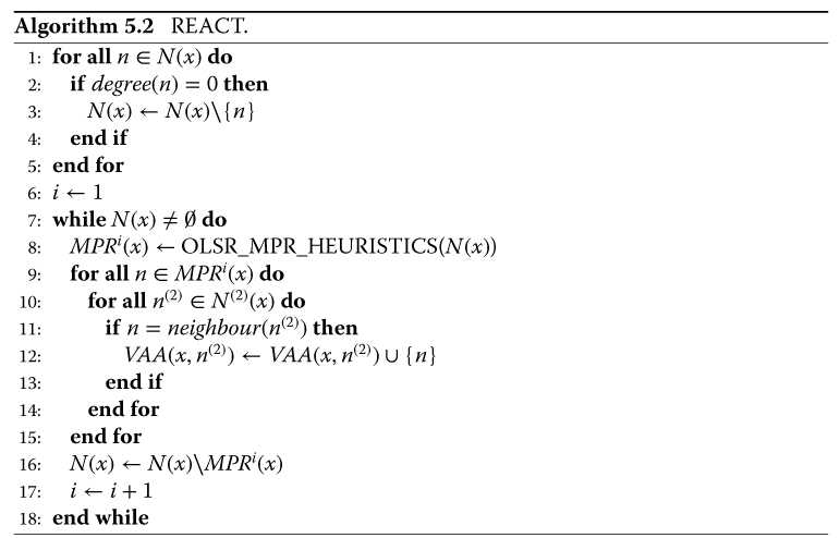
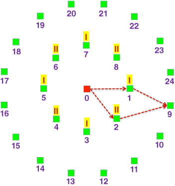
Figure 5.7 REACT scenario.
Looking at this scenario, one should note that the relay nodes marked ‘I’ are those that would be selected by the classic multi-point relay station selection heuristics, whereas the ones marked ‘II’ belong to the redundant secondary set of multi-point relays additionally selected by the routing information enhanced algorithm for cooperative transmission. To reduce the complexity of the simulated configuration, the maximum size of the virtual antenna array is limited to 2, so that the full-rate ![]() code matrix is applicable, originally proposed by Alamouti (1998); other matrices would still be applicable (Tarokh et al., 1999). Consequently, once the routing information enhanced algorithm for cooperative transmission has been activated, the primary
code matrix is applicable, originally proposed by Alamouti (1998); other matrices would still be applicable (Tarokh et al., 1999). Consequently, once the routing information enhanced algorithm for cooperative transmission has been activated, the primary ![]() and secondary
and secondary ![]() sets are created. In fact, this is where the first indication of the readiness of the proposed solution for incorporation into the Autonomic Cooperative Networking Architectural Model becomes clearly visible, as the latter set may be used autonomically, should an increase in the control overhead become necessary. Based on both these sets, as well as on the assumption that the data stream originates from source node 0 and is destined for destination node number 9,
sets are created. In fact, this is where the first indication of the readiness of the proposed solution for incorporation into the Autonomic Cooperative Networking Architectural Model becomes clearly visible, as the latter set may be used autonomically, should an increase in the control overhead become necessary. Based on both these sets, as well as on the assumption that the data stream originates from source node 0 and is destined for destination node number 9, ![]() is created at the beginning of the simulation, as indicated in Figure 5.7. However, since the relay nodes and the destination node are assumed to be mobile and moving around at a speed of 5 km h
is created at the beginning of the simulation, as indicated in Figure 5.7. However, since the relay nodes and the destination node are assumed to be mobile and moving around at a speed of 5 km h![]() , the assignment of relay nodes to
, the assignment of relay nodes to ![]() will be dynamic during the entire course of the simulation analysis, as outlined by Wódczak (2014a).
will be dynamic during the entire course of the simulation analysis, as outlined by Wódczak (2014a).
Although the devised simulation environment supported switching between single-path relaying and the routing information enhanced algorithm for cooperative transmission mode, it was guaranteed that at least two relay nodes would be available in the region of interest, so that DSTBC-enabled cooperative transmission was continuous. As such, the analysis was carried out on the downlink, where single-input multiple-output, at the first hop, and multiple-input single-output, at the second hop, block Rayleigh channels were used, as described by Wódczak (2012a). The channel coefficients for the links between distinct pairs of network nodes were generated according to the previously described formulas, as originally proposed by Zheng and Xiao (2003). The total transmitted power, either by a single network node or a virtual antenna array, was always normalised to unity. Also, the quadrature phase-shift keying (QPSK) modulation scheme was used, and the signal was perturbed by additive white Gaussian noise with zero mean and ![]() variance per dimension. Given such a simulation configuration, both the single-path relaying mode, where the transmission was assisted by one relay node only, and the routing information enhanced algorithm for cooperative transmission mode, exploiting two relay nodes, were investigated. The corresponding results are presented in Figure 5.8, where the numbers placed in the legend next to the names of the specific system configurations are used to identify the next hop neighbour node or neighbour nodes. Next, the focus is to be shifted more towards the complementary evolved messaging structure (Wódczak, 2014a).
variance per dimension. Given such a simulation configuration, both the single-path relaying mode, where the transmission was assisted by one relay node only, and the routing information enhanced algorithm for cooperative transmission mode, exploiting two relay nodes, were investigated. The corresponding results are presented in Figure 5.8, where the numbers placed in the legend next to the names of the specific system configurations are used to identify the next hop neighbour node or neighbour nodes. Next, the focus is to be shifted more towards the complementary evolved messaging structure (Wódczak, 2014a).

Figure 5.8 Performance of REACT.
5.3.2 Evolved Messaging Structure
Attempting to understand the limitations of the Optimised Link State Routing protocol, one should note that too rough a Link Type classification it offers could make the entire process of virtual antenna array preselection rather ineffective, thereby spoiling the expected gain from cooperative transmission. Simply because such a generic Link Type allocation may seem justified in the context of mobile ad hoc networks, where knowledge of whether a link is symmetric or not suffices for the orchestration of the communications, the cooperative transmission approach calls for much more detailed feedback regarding the power level of the signal between neighbour nodes. As the Optimised Link State Routing protocol implies that each network node may group all the Neighbour Interface Addresses characterised by both the same Link Type and Neighbour Type in a single Link Message, the imprecise Link Type information becomes advantageous, since it guarantees that a number of Neighbour Interface Addresses are assigned to the same Link message, whereas increasing the accuracy could reduce the effectiveness of the protocol in terms of its control overhead (Wódczak, 2012a). While the achievable trade-off in terms of accuracy and overhead is yet to be scrutinised in detail, the evolution of the messaging structure is presented below. First, the emphasis will be laid on the Link Type and Neighbour Type in order to justify the modifications to follow. Then the Modified Hello message structure will be presented along with its respective Extended Link Code (ELC) and Extended Link Mask (ELM). Finally, following Wódczak (2012a), the format of the Generalised Hello message will be outlined.
Leveraging the evolved messaging structure (EMS), as outlined by Wódczak (2012a), for the needs of this book, it seems apparent that the Link Code of the Hello message becomes instrumental in the introduction of all the relevant modifications. This is mostly because of its internal structure, as depicted in Figure 5.9, which may be both an indicator of the existing limitations of and the areas for improvement with regard to the Optimised Link State Routing protocol. Essentially, as adapted in Table 5.9, this protocol is able to collect merely very generic parameters for the radio connections between the neighbour nodes, which results in the assignment of specific links to four distinct groups: UNSPEC_LINK, ASYM_LINK, SYM_LINK, and LOST_LINK (Clausen and Jacquet, 2003). While such a classification may be sufficient for the functioning of the said mobile ad hoc network, the enabling mechanism for cooperative transmission requires much more precise parameters, as indicated by Wódczak (2014a). What is more, the selection of the complementary Neighbour Types also appears to be somewhat restricted, as only the values NOT_NEIGH, SYM_NEIGH, and MPR_NEIGH are available. Yet, not too much effort will be required to arrange for an expansion in this respect, as the existence of an additional and not yet allocated Neighbour Type makes the introduction of the new value of VAA_NEIGH fairly straightforward, as described in Table 5.10 (Clausen and Jacquet, 2003). Thus it becomes feasible to produce the first stage of the concept behind enabling cooperative transmission between or among multi-point relay stations using virtual antenna arrays (Wódczak, 2014a).15
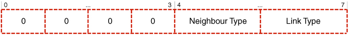
Figure 5.9 Link Code. Adapted from Clausen and Jacquet (2003).
Table 5.9 Link types. Adapted from Clausen and Jacquet (2003)
| Link Type | Value | Description |
| UNSPEC_LINK | 0 | Indicates that no information about a given link is specified. |
| ASYM_LINK | 1 | Indicates that a given link is asymmetric, which means that it is only heard. |
| SYM_LINK | 2 | Indicates that a given link is symmetric and heard bidirectionally in both directions. |
| LOST_LINK | 3 | Indicates that a given link has been lost. |
Table 5.10 Neighbour types. Adapted from Clausen and Jacquet (2003), as well as from Wódczak (2014)
| Neighbour Type | Value | Description |
| NOT_NEIGH | 0 | Indicates that a given network node is no longer considered as or has not yet become a symmetric neighbour of a specific network node. |
| SYM_NEIGH | 1 | Indicates that there exists at least one symmetric link between this network node and a given neighbour node. |
| MPR_NEIGH | 2 | Indicates that there exists at least one symmetric link between this network node and a given neighbour node, additionally selected as an MPR. |
| VAA_NEIGH | 3 | Indicates that there exists at least one symmetric link between this network node and a given neighbour node, additionally selected as an element of a given VAA. |
In order to expand the capability of the Optimised Link State Routing protocol in terms of enabling more accurate link quality collection, a Modified Hello message16 format is introduced, as depicted in Figure 5.10, where a 16 bit Extended Link Code field is allocated to replace the originally available Link Code and Reserved fields (Wódczak, 2012a). The structure of such an Extended Link Code is outlined in Figure 5.11. In particular, it is suggested that the four MSBs of the Link Code field be used along with eight bits of the Reserved field in order to constitute the Power Level field of total length 12 bits, so that additional information on the power level of the radio signal between neighbouring network nodes can be conveyed. As a result, the network node ![]() will be able to find out whether its one-hop neighbour
will be able to find out whether its one-hop neighbour ![]() can hear the signals it transmits, and also learn what the precise power level of such a signal would be. Moreover, as the Hello messages periodically disseminated by each network node
can hear the signals it transmits, and also learn what the precise power level of such a signal would be. Moreover, as the Hello messages periodically disseminated by each network node ![]() usually contain similar information pertaining to its one-hop neighbourhood, potentially forming the two-hop neighbourhood of network node
usually contain similar information pertaining to its one-hop neighbourhood, potentially forming the two-hop neighbourhood of network node ![]() , the latter could acquire a far more concrete overview of the link parameters in its entire one-hop and two-hop neighbourhoods, especially if radio channel reciprocity is assumed.17 However, this modification to the Hello message format would no longer be completely transparent to the workings of the Optimised Link State Routing protocol. In other words, unlike the initial modification, where it was sufficient to make the protocol aware of the new VAA_NEIGH type, here the situation appears more demanding.
, the latter could acquire a far more concrete overview of the link parameters in its entire one-hop and two-hop neighbourhoods, especially if radio channel reciprocity is assumed.17 However, this modification to the Hello message format would no longer be completely transparent to the workings of the Optimised Link State Routing protocol. In other words, unlike the initial modification, where it was sufficient to make the protocol aware of the new VAA_NEIGH type, here the situation appears more demanding.
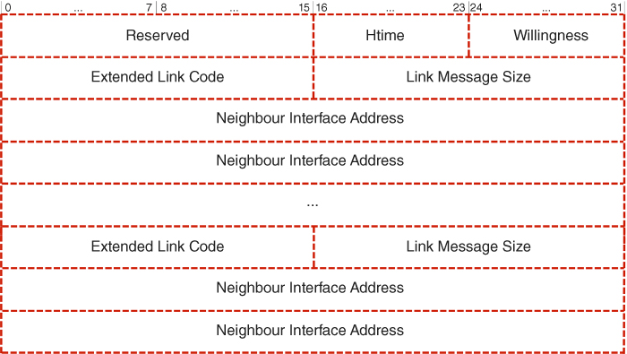
Figure 5.10 Modified Hello message.
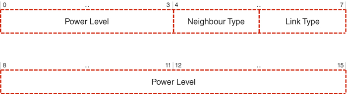
Figure 5.11 Extended Link Code.
Now, not only is the Reserved field to be utilised, which, according to the specification, should remain unaltered, but also the aforementioned four MSBs are to be exploited, which, despite being meant for future extensions, are still not straightforwardly applicable to the contemplated modification (Wódczak, 2012a). Therefore, in order to overcome any such issues, a compromise attempt guaranteeing backward compatibility is needed. In essence, should a Hello message be processed for the purposes of performing the classic protocol operations, the newly introduced Extended Link Code field would need to be masked by application of the Extended Link Mask, as depicted in Figure 5.12. Going further, it would mean that any specific implementation of an accordingly modified Optimised Link State Routing protocol would need to exploit the Extended Link Mask to perform the operation of logical conjunction over all the Extended Link Codes included in a specific Modified Hello message.18 The only exception to this rule would hold when the Power Level data should be accessed for arranging for and orchestrating cooperative transmission. Even though such an approach would seem appropriate from the backward compatibility perspective, one could also consider the introduction of a Generalised Hello message, as depicted in Figure 5.13. However, its format would be bound to differ from both the structure of the original and the Modified Hello message, as it lacks the Link Message Size field to allow overhead optimisation by avoiding Link messages that would contain a single Neighbour Interface Address only (Wódczak, 2012a).
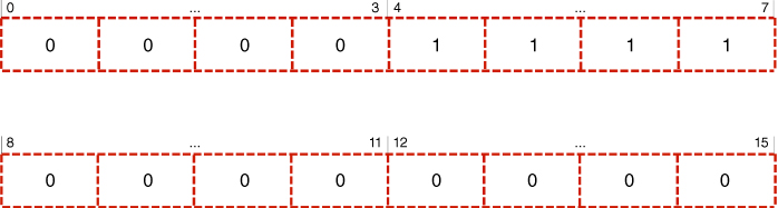
Figure 5.12 Extended Link Mask.
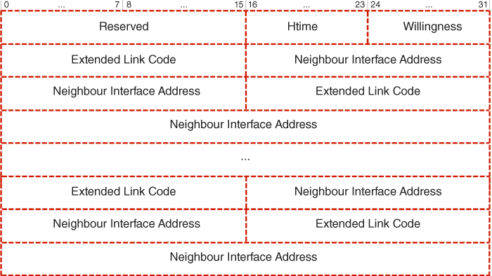
Figure 5.13 Generalised Hello message.
5.3.3 Address Auto-Configuration and Duplication
Attempting to propose certain cooperative transmission related extensions in the form of the above-mentioned REACT to be contained under the umbrella of the Generic Autonomic Network Architecture, one needs to take into consideration a much wider context of network discovery and configuration, going beyond what may be covered by the Optimised Link State Routing protocol alone. On the one hand, the Generic Autonomic Network Architecture is fully integrated with Internet Protocol version 6 (IPv6) which provides certain mechanisms of relevance, such as the Neighbour Discovery (ND) protocol. Among others, as outlined by Narten et al. (2007), Neighbour Discovery is exploited by network nodes sharing the same link to discover the presence of each other or one another. On the other hand, however, apart from the discovery aspects, there may appear a highly sensitive configuration-related issue, especially likely to be encountered in mobile ad hoc networks, where address duplication could take place under certain circumstances. In essence, one may think of an unlikely, yet possible, situation where a lack of direct visibility between network nodes and the stateless approach to address auto-configuration (AAC) would result in such address duplication. Since both the above-mentioned aspects are vital for networked setups of the scale under consideration for the Autonomic Intelligence Evolved Cooperative Networking, where the design principles of the Generic Autonomic Network Architecture hold, below its characteristics related to both address auto-configuration and duplicate address detection are described.
Most generally, thanks to the mechanism of Neighbour Discovery, a group of network nodes should be able not only to auto-discover themselves in a possibly new context, but in the event that a given neighbour node of theirs becomes no longer available, they could actively search for relevant up-and-running alternatives. Moving into the details, following Narten et al. (2007), should a network interface be activated, a given network node becomes entitled to commence the distribution of Router Solicitation messages in order to stimulate other neighbour nodes to generate their Router Advertisement messages immediately. In general, based on the information acquired in this way, a given host19 may start address auto-configuration. Then, routers may use the Router Advertisement messages in order to indicate whether a given host should proceed with the stateless or stateful process, as classified in Figure 5.14. In the case of stateless address auto-configuration (SLAAC), as outlined by Thomson et al. (2007), each host can generate its address as a combination of subnetwork and interface identifiers, which appears very convenient, as long as they are unique and properly routable, while there are no requirements as to their specific properties. Following the design guidelines given by Thomson et al. (2007), it is assumed that manual configuration shall be not required, while neither small networks, where the same link is shared, nor large networks, composed of subnetworks, shall require stateful address auto-configuration (SFAAC). While in the former case all the addresses will share the same prefix, in the latter each subnetwork will be assigned its own prefix. Lastly, the possibility of renumbering provision shall be guaranteed in any of the cases.
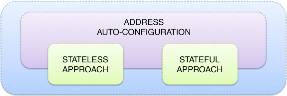
Figure 5.14 Address auto-configuration.
Stateful address auto-configuration is characterised by the existence of Dynamic Host Configuration Protocol (DHCP) servers delivering configuration parameters to network nodes. Such parameters are by no means limited to IPv6 addresses and may include other information carried as options. The DHCP clients, in turn, transmit their messages to a reserved multicast address of link scope, so they do not need to be configured with the address or addresses of the DHCP servers, as indicated by Droms et al. (2003). In the case that a given network node and a given DHCP server are not connected to the same link, a DHCP relay agent acts as an intermediary network node to take care of proper delivery, at the same time operating transparently from the perspective of the network node itself. Once a given network node determines the address of the DHCP server, it might contact this server directly in some cases. Most importantly, these mechanisms were designed for infrastructure-based environments and there are still a number of open issues regarding mobile ad hoc networks, as outlined by Bernardos et al. (2010). In particular, following the cited publication, stateless address auto-configuration assumes that each network node is able to communicate directly with all the other network nodes, as if all of them were connected to a single multicast link, which obviously need not be the case, while, according to stateful address auto-configuration each network node should be able to communicate either with the DHCP server or the relay agent, which again need not hold true. What is more, one should keep in mind the pertinent issues related to multi-hop support and network merging and partitioning (Bernardos et al., 2010).20
Shifting from address auto-configuration to duplicate address detection (DAD), it was previously claimed that, under certain circumstances, especially inherent in mobile ad hoc networks, the issue of address duplication could take place even in a system characterised by a correct initial configuration. In other words, it cannot be excluded that physical separation, for example, as depicted in Figure 5.15, might result in two network nodes being assigned the same IPv6 address. One should note, however, that in some cases such duplication may take place without any physical obstacles, as it all boils down to the workings of a specifically applied protocol. In particular, analysing the duplicate address avoidance (DAA) aspects of the specification of Neighbour Discovery in IPv6 networks by Narten et al. (2007), both neighbour solicitation and proper seed calculation appear to be implied as the preferred countermeasures against this cumbersome phenomenon. Regardless of the way the address duplication took place, there appear to exist a number of methods for coping with it in different ways, as classified in a very detailed survey by Bernardos et al. (2010). Given the scope of this book, the first part of the survey appears of highest relevance because it is related to standalone mobile ad hoc network scenarios. However, taking into account that the major emphasis here is on the Optimised Link State Routing protocol concepts, the three most pertinent approaches, as described in Table 5.11, are summarised below in a more detailed way; for a thorough analysis containing all the references, the reader is pointed directly to Bernardos et al. (2010).
Figure 5.15 Address duplication scenario.
Table 5.11 Duplicate address detection for the OLSR protocol
| Approach | Characteristics |
| No overhead auto-configuration OLSR | Passive duplicate address detection approach is used together with the OLSR protocol. It is based on the observation that some protocol events occur generally for duplicate addresses and rarely for unique ones. |
| Passive duplicate address detection for OLSR | Algorithmic approach aiming to detect duplicate addresses through different parameters contained in Hello and TC messages, as well as the addresses of OLSR protocol messages and IP headers. |
| Address auto-configuration in OLSR | Network nodes periodically disseminate their addresses and a randomly generated sequence of bits of a fixed length. Duplicate addresses exist if the identifiers for a given address do not match. |
Examining the approaches most suited to the major theme of this book, first comes the no overhead auto-configuration OLSR (NOA-OLSR) extension proposed by Mase and Adjih (2006). In particular, this approach is intended for both the initial address auto-configuration and duplicate address detection, while keeping the Optimised Link State Routing protocol operating in the usual manner. One should note, however, that a network node may only be allowed to fully run the Optimised Link State Routing protocol after it has been confirmed that its address is unique. In the meantime, the network node goes through different states and is considered by its neighbour nodes as not fully reliable. As such, the process of address auto-configuration involves three stages in the form of address generation, progressive duplicate address detection, and gradual admittance to the network connected with avoidance of routing table contamination (Mase and Adjih, 2006). Essentially, during the first stage, a given network node monitors the message flow in the network to create a list of addresses in use. Based on this, it becomes entitled to select a still tentative address not in the list, yet the specific procedure is not defined in detail. In the second stage the process of duplicate address detection is commenced, which consists in checking for inconsistencies in both the Hello and TC messages, and also in the sequence numbers. With the third stage, the network node is gradually admitted to the network so that an increasing number of other network nodes can use its messages, while it is still verified if it has passed the duplicate address detection procedure in order to become included in the routing table.
Then there is the passive duplicate address detection OLSR (PDAD-OLSR) extension, which is based on a set of algorithms designed to allow the network nodes to detect conflicts in the network by observing protocol anomalies, as outlined by Mase and Weniger (2006). In general, such an approach may be translated into the assumption that some protocol-related events may clearly occur should duplicate addresses exist, while being extremely unlikely in the case of unique assignments, as explained by Baccelli et al. (2005). In particular, a network node running PDAD-OLSR may obtain information about the state of the entities governing the behaviour of the routing protocol running at other network nodes on the basis of analysis of the incoming messages. What is more, the network node performing such an analysis must be aware of the exact time at which the message was dispatched. Should this not be the case, some vital decisions could become immediately outdated, as the state of the routing protocol is, most obviously, undergoing continual changes with the passage of time. Thus, the above-mentioned algorithms used by network nodes for the purposes of duplicate address detection make use of different parameters of the Hello and TC messages, such as link states, link codes, message sequence numbers, as well as the addresses contained in the Optimised Link State Routing protocol messages and the IP headers. Consequently, it is possible to ensure that the multi-point relay station selection heuristics may remain unaffected (Mase and Weniger, 2006).
Last, but not least, comes address auto-configuration OLSR (AAC-OLSR),21 which is targeted at guaranteeing address uniqueness in very demanding situations, when different mobile ad hoc networks are about to undergo the process of merging. The method proposed by Adjih et al. (2005) assumes a distributed approach, where each network node is expected to periodically send out both the list of all its addresses and its identifier using so-called Multiple Address Declaration (MAD) messages. In particular, first of all, an incoming network node assigns itself an address by means of random selection, acquisition of an address advertised by another network node as unused, or exchange of control messages. What follows is duplicate address detection performed by means of analysing the MAD messages, so that when a given network node finds its own address on the list yet characterised by a different identifier, it chooses a new address for itself. Such a problem typically occurs when networks merge, which means that other network nodes also detect the related addressing conflict, and should all of them start announcing it, there could be a significant control overhead increase. This is why it is suggested that the MAD messages are allowed to reach all the network nodes in the network before the conflicting situation is announced to the network nodes, since, otherwise, the network could inevitably find itself in the situation referred to as a ‘broadcast storm’ (Adjih et al., 2005). As such, the approach does not exclude optional routines such as the avoidance of routing table contamination or passive duplicate address detection.
5.4 Node Level Overlay Logic
5.4.1 Autonomic Cooperative Networking Protocol
Following the prior analysis of the rationale behind the concept of the Autonomic Cooperative Node, the incremental description towards the ultimate Autonomic Cooperative Networking Architectural Model is continued with the next major component in the form of the Autonomic Cooperative Networking Protocol (ACNP) (Wódczak, 2014a). Essentially, the Autonomic Cooperative Networking Protocol fulfils the classification of a cross-layer solution by not only incorporating the workings of the Optimised Link State Routing protocol residing at the network layer, but also being profoundly rooted in the distributed space-time block coding inherent in the link layer, as well as indirectly reaching the physical layer to orchestrate the virtual multiple-input multiple-output (VMIMO) radio channel. In other words, remaining in the dimension of the Open Systems Interconnection Reference Model, one could justly say that the Autonomic Cooperative Networking Protocol capitalises directly on the workings of the extended routing information enhanced algorithm for cooperative transmission (EREACT), as outlined by Wódczak (2007). There is, however, profound added value differentiating the two, as all the building blocks of the Autonomic Cooperative Networking Protocol make it fully integrated into the perpendicular or orthogonal dimension of the Generic Autonomic Network Architecture. Given such a context, first of all, the emphasis is to be laid on the elevated building blocks, especially involving the consolidated notion of the Autonomic Cooperative Behaviour (ACB). Then, the incorporation of the already discussed evolved messaging structure will be justified, along with the introduction of a properly enabled routing table design.
In particular, analysing the transition22 from EREACT to the Autonomic Cooperative Networking Protocol, one should note that, on the one hand, as described earlier in this chapter, certain parts of the former were already outlined on the occasion of introducing the evolved messaging structure on the basis of the original REACT. On the other hand, the upgraded algorithmic description driving the behaviour of EREACT will not be outlined until the logic behind the cooperation management decision element (CMDE) has been presented in the next section. Such an approach should by no means be read as restrictive, because at this stage those will be mostly the elevated building blocks to be upgraded from the terminological perspective. Essentially, one should note that, as long as the Autonomic Cooperative Networking Protocol has been designed to fuse certain workings of both the link layer and the network layer, its role is to orchestrate Autonomic Cooperative Behaviour instantiated between or among Autonomic Cooperative Nodes, forming an elevated version of VAAs, presently referred to as ACSs. So, much as the Autonomic Cooperative Nodes may be perceived as an upgraded incarnation of relay nodes or multi-point relays, depending on the context,23 the concept of Autonomic Cooperative Behaviour, described in the previous chapter, brings a completely new value to what was previously known as EREACT.24
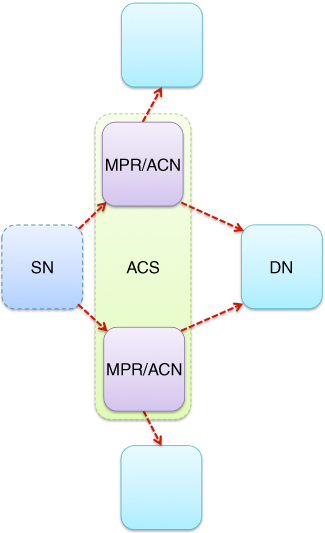
Figure 5.16 Integration of MPRs and ACNs.
Key to the analysis appears to be the integration between the MPRs and ACNs, as depicted in Figure 5.16, which stems directly from and builds upon the rationale behind the concept of EREACT, where the multi-point relay station selection heuristics was similarly employed to facilitate VAA-aided cooperative transmission, as introduced by Wódczak (2012a). Even though the idea of VAAs was elevated by Wódczak (2014a) to institute the notion of virtual cooperative sets (VCSs), or using the latest nomenclature, the said ACSs, while the already legacy relay nodes were replaced with the latest Autonomic Cooperative Nodes, the major assumption still consists in the execution of the multi-point relay station selection heuristics in an iterative manner in order to identify those Autonomic Cooperative Nodes that could act together as ACSs and, thus, expose Autonomic Cooperative Behaviour through the DSTBC-driven orchestration of the virtual multiple-input multiple-output radio channel. In fact, as the Optimised Link State Routing protocol belongs to the network layer, each of the Autonomic Cooperative Nodes is not only entitled to acquire the knowledge of its one-hop and two-hop neighbourhoods, but may equally well identify such one-hop neighbour nodes as would be able to provide connectivity to some preselected two-hop neighbour node, in turn. From these, solely neighbour nodes, or rather relay nodes,25 may be identified as Autonomic Cooperative Nodes which help minimise the protocol control overhead.
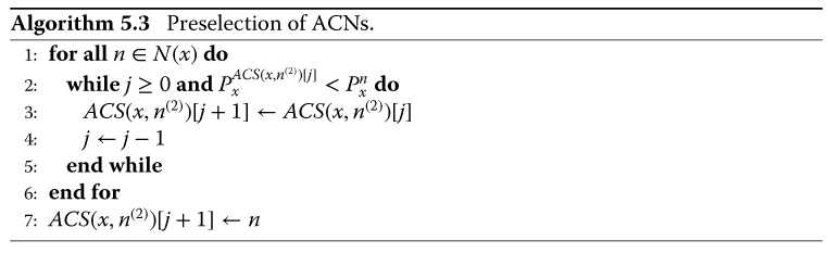
Moving towards the justification for the introduction of the previously outlined evolved messaging structure, one might recall Figure 5.8, where the bit error rate curves almost overlapped in the region of low signal-to-noise ratio (SNR) values. This was undoubtedly related to the fact that the first-hop errors were propagated further during the second hop, as analysed by Wódczak (2012a). It was so since the first-hop transmission, where the source node feeds the preselected relay nodes, or, using the present nomenclature, the Autonomic Cooperative Nodes, with the aid of single-input single-output radio links, is less robust to radio channel impairments when compared to the DSTBC-enhanced cooperative transmission at the second hop, where the Autonomic Cooperative Nodes, forming an Autonomic Cooperative Set, feed the destination node. The question then arises of what gain could be achievable should a better preselection be made on the basis of more accurate link parameters at the first hop only. In order to quantify their influence, the logic outlined in Algorithm 5.3 is validated, where the entire set ![]() is explored to find and promote these potential Autonomic Cooperative Nodes, which appear to be characterised by the highest received power level expressed as
is explored to find and promote these potential Autonomic Cooperative Nodes, which appear to be characterised by the highest received power level expressed as ![]() . In particular, two different cases are evaluated, where the SNR value at the first hop is maintained at the level of either 10 dB or 20 dB, as outlined by Wódczak (2012a). The results are depicted in Figure 5.17, where the numbers in the legend denote either the first hop neighbour node or Autonomic Cooperative Nodes, forming an Autonomic Cooperative Set, following the original notation of Figure 5.7.
. In particular, two different cases are evaluated, where the SNR value at the first hop is maintained at the level of either 10 dB or 20 dB, as outlined by Wódczak (2012a). The results are depicted in Figure 5.17, where the numbers in the legend denote either the first hop neighbour node or Autonomic Cooperative Nodes, forming an Autonomic Cooperative Set, following the original notation of Figure 5.7.
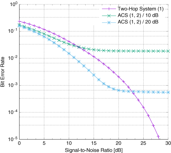
Figure 5.17 Performance for first-hop 10 dB or 20 dB SNR.
The above analysis helps to answer the question of what bit error rate one could expect in the case of an equivalent dynamic system, where the source node could preselect such Autonomic Cooperative Nodes that would observe the received power level ![]() remaining, respectively, 10 dB or 20 dB higher than the mean noise power
remaining, respectively, 10 dB or 20 dB higher than the mean noise power ![]() .26 Indeed, the expected gain in bit error rate appears observable, becoming higher for higher theoretically guaranteed SNRs. Most importantly, such a system begins to saturate at values close to the assumed 10 dB or 20 dB, thereby additionally showing that the first hop is critical in this respect, which justifies the incorporation of the Extended Link Code. In particular, the availability of additional power level information conveyed within such an Extended Link Code of the Modified Hello message makes it possible to place the Autonomic Cooperative Nodes in
.26 Indeed, the expected gain in bit error rate appears observable, becoming higher for higher theoretically guaranteed SNRs. Most importantly, such a system begins to saturate at values close to the assumed 10 dB or 20 dB, thereby additionally showing that the first hop is critical in this respect, which justifies the incorporation of the Extended Link Code. In particular, the availability of additional power level information conveyed within such an Extended Link Code of the Modified Hello message makes it possible to place the Autonomic Cooperative Nodes in ![]() at positions derived from the strength of the signal heard by the destination node.27 In general, should a network layer entity be about to send a packet to a destination node at R_dest_addr,28 it would need to use R_next_addr and request the link layer to handle the transmission to the medium access control (MAC) address29 corresponding to R_next_addr. However, in the case of the Autonomic Cooperative Networking Protocol, such a packet would need to be transmitted concurrently over all the Autonomic Cooperative Nodes belonging to a given ACS (Wódczak, 2012a). This issue could be addressed by associating an additional routing table with each column of the space-time block coding matrix, which leads to a multidimensional form thereof, as depicted in Figure 5.18.
at positions derived from the strength of the signal heard by the destination node.27 In general, should a network layer entity be about to send a packet to a destination node at R_dest_addr,28 it would need to use R_next_addr and request the link layer to handle the transmission to the medium access control (MAC) address29 corresponding to R_next_addr. However, in the case of the Autonomic Cooperative Networking Protocol, such a packet would need to be transmitted concurrently over all the Autonomic Cooperative Nodes belonging to a given ACS (Wódczak, 2012a). This issue could be addressed by associating an additional routing table with each column of the space-time block coding matrix, which leads to a multidimensional form thereof, as depicted in Figure 5.18.
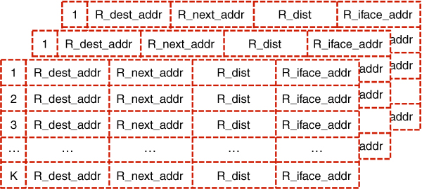
Figure 5.18 ACNP routing table.
5.4.2 Cooperation Management Decision Element
Progressing even further towards the perpendicular or orthogonal dimension determined by the Generic Autonomic Network Architecture one immediately comes across the cooperation management decision element (CMDE), whose inner logic is directly programmed to orchestrate the composition of Autonomic Cooperative Behaviour with the multi-point relay station selection heuristics of the Optimised Link State Routing protocol. As such, the heuristics is executed iteratively over the set of one-hop neighbour nodes, ![]() , of a given source node, until all the Autonomic Cooperative Nodes potentially meeting the selection criteria have been assigned to distinct
, of a given source node, until all the Autonomic Cooperative Nodes potentially meeting the selection criteria have been assigned to distinct ![]() subsets. Looking more into the details, one should note that the routine being outlined very much mirrors the workings of EREACT. On top of this, it is also assumed that all the Autonomic Cooperative Nodes can expose the said Autonomic Cooperative Behaviour, and thus could be perceived as being capable of forming Autonomic Cooperative Sets. Consequently, each iteration will similarly result in redundant subsets of multi-point relays, i.e. secondary, ternary, and so on, denoted as
subsets. Looking more into the details, one should note that the routine being outlined very much mirrors the workings of EREACT. On top of this, it is also assumed that all the Autonomic Cooperative Nodes can expose the said Autonomic Cooperative Behaviour, and thus could be perceived as being capable of forming Autonomic Cooperative Sets. Consequently, each iteration will similarly result in redundant subsets of multi-point relays, i.e. secondary, ternary, and so on, denoted as ![]() , thereby making it possible to distribute all the Autonomic Cooperative Nodes, on the basis of additional power level information, among the most relevant Autonomic Cooperative Sets. In the light of the above, the algorithmic description defining the logic behind the CMDE will be outlined first, so that the relevant scenario overview and performance results may follow, to be complemented with an analysis of the potential control overhead.
, thereby making it possible to distribute all the Autonomic Cooperative Nodes, on the basis of additional power level information, among the most relevant Autonomic Cooperative Sets. In the light of the above, the algorithmic description defining the logic behind the CMDE will be outlined first, so that the relevant scenario overview and performance results may follow, to be complemented with an analysis of the potential control overhead.
Essentially, as adapted in Algorithm 5.4,30 one should note that, similarly to VAAs, the ACSs, denoted as ![]() , are designed to support cooperative transmission on the two-hop path between the source node
, are designed to support cooperative transmission on the two-hop path between the source node ![]() and the destination node
and the destination node ![]() . What is more, the general outline of the proposed logic resembles the previously analysed Algorithm 5.2 to such an extent that again each network node
. What is more, the general outline of the proposed logic resembles the previously analysed Algorithm 5.2 to such an extent that again each network node ![]() characterised by a zero degree, i.e.
characterised by a zero degree, i.e. ![]() , is first removed by the source node
, is first removed by the source node ![]() from the one-hop set of neighbour nodes
from the one-hop set of neighbour nodes ![]() . What becomes clear after additional inspection, however, is that it also incorporates certain aspects of Algorithm 5.3, where the awareness of the power level issue was investigated. In fact, the extended logic extensively exploits any additional information regarding the power level of the signals received by a given network node from its one-hop neighbour nodes, as collected by the relevantly modified version of the Optimised Link State Routing protocol, where the evolved messaging structure described earlier is employed. In particular, such information is stored in the Power Level field of the Extended Link Code, so that, based on the value it carries, the placement of a specific neighbour node of the source node in
. What becomes clear after additional inspection, however, is that it also incorporates certain aspects of Algorithm 5.3, where the awareness of the power level issue was investigated. In fact, the extended logic extensively exploits any additional information regarding the power level of the signals received by a given network node from its one-hop neighbour nodes, as collected by the relevantly modified version of the Optimised Link State Routing protocol, where the evolved messaging structure described earlier is employed. In particular, such information is stored in the Power Level field of the Extended Link Code, so that, based on the value it carries, the placement of a specific neighbour node of the source node in ![]() may be adjusted accordingly, allowing it to take the position corresponding directly to the power level at which it was heard by the destination node. This means that, again, the Autonomic Cooperative Nodes taking the most elevated positions in a given Autonomic Cooperative Set will, at least theoretically, provide the best connectivity to the said destination node, thereby additionally optimising the process of preselection.
may be adjusted accordingly, allowing it to take the position corresponding directly to the power level at which it was heard by the destination node. This means that, again, the Autonomic Cooperative Nodes taking the most elevated positions in a given Autonomic Cooperative Set will, at least theoretically, provide the best connectivity to the said destination node, thereby additionally optimising the process of preselection.
The operation of a CMDE defined in this way is verified in a low-mobility and high-density hot-spot scenario, where mobile Autonomic Cooperative Nodes are taken into account, moving around at velocities in the range 0–5 km h![]() (equivalent to 0–1.4 m s
(equivalent to 0–1.4 m s![]() ). In particular, following Dottling et al. (2009), a line-of-sight channel model is assumed, characterised by the path loss
). In particular, following Dottling et al. (2009), a line-of-sight channel model is assumed, characterised by the path loss ![]() , defined as
, defined as
where ![]() represents the distance, expressed in meters,
represents the distance, expressed in meters, ![]() m, while the standard deviation of the shadow fading
m, while the standard deviation of the shadow fading ![]() is 1.3 dB. What is more, the source node, taking the form of a fixed base station (BS) in this scenario, is assumed to transmit with an average power of 200 mW and is equipped with an antenna characterised by a gain of 8 dBi. The mobile relay nodes and the destination node are all embodied by user terminals (UTs), characterised by the corresponding parameters being equal to 200 mW and 0 dBi, respectively.31 In particular, the downlink is investigated and QPSK modulation is assumed, while the noise figure introduced by the radio frequency chain of a UT is assumed to be 7 dB. Essentially, the analysed network topology, as presented in Figure 5.19, very much resembles a mobile ad hoc network configuration in the access part, except for the BS. The destination UT (18) is located 29 m from the BS (0), while the distances between the BS and each UT belonging to the first (1–6) and second groups (7–17) are 10 m and 24 m, respectively.32
is 1.3 dB. What is more, the source node, taking the form of a fixed base station (BS) in this scenario, is assumed to transmit with an average power of 200 mW and is equipped with an antenna characterised by a gain of 8 dBi. The mobile relay nodes and the destination node are all embodied by user terminals (UTs), characterised by the corresponding parameters being equal to 200 mW and 0 dBi, respectively.31 In particular, the downlink is investigated and QPSK modulation is assumed, while the noise figure introduced by the radio frequency chain of a UT is assumed to be 7 dB. Essentially, the analysed network topology, as presented in Figure 5.19, very much resembles a mobile ad hoc network configuration in the access part, except for the BS. The destination UT (18) is located 29 m from the BS (0), while the distances between the BS and each UT belonging to the first (1–6) and second groups (7–17) are 10 m and 24 m, respectively.32
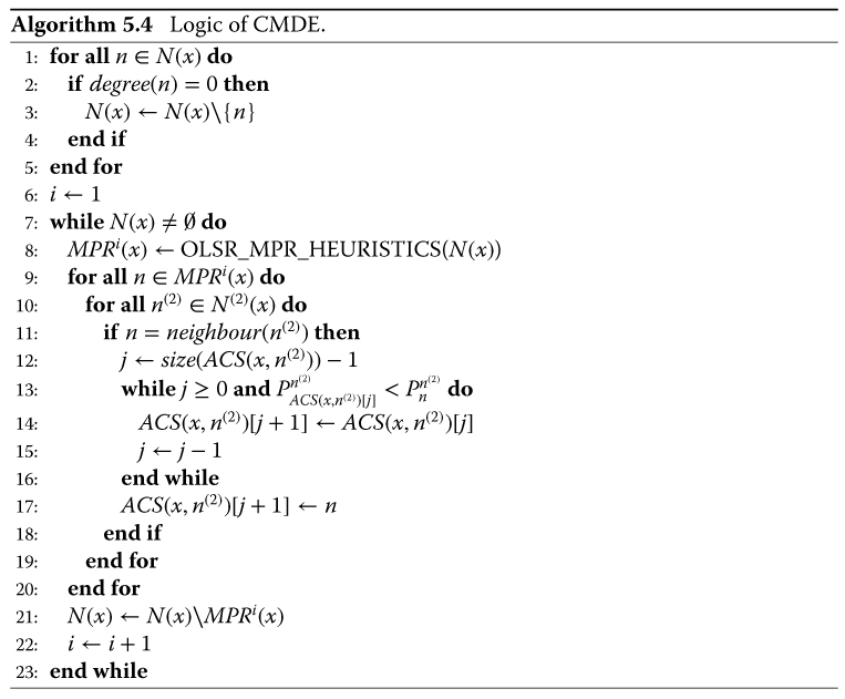
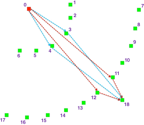
Figure 5.19 Evaluation scenario.
The related computer-assisted simulations were performed in the presence of a zero-mean additive white Gaussian noise characterised by power level ![]() expressed in dBW, where the transmission was originated by the BS (0) and destined for UT (18). First of all, although it was assumed that the destination UT is conceptually not a neighbour node of the BS, the performance of the one-hop link towards this UT was evaluated as the worst, reference, case. Then two different configurations of conventional relaying were tested, where the transmission was assisted either by UT (3) or UT (12). An advantage was observable, especially in the latter case, where the relaying UT was situated closer to the destination node so that the antenna gain of the BS could be more efficiently exploited. Finally, both REACT and ACNP were validated, where, in the case of the former, ACN (3) and ACN (4) were selected to form
expressed in dBW, where the transmission was originated by the BS (0) and destined for UT (18). First of all, although it was assumed that the destination UT is conceptually not a neighbour node of the BS, the performance of the one-hop link towards this UT was evaluated as the worst, reference, case. Then two different configurations of conventional relaying were tested, where the transmission was assisted either by UT (3) or UT (12). An advantage was observable, especially in the latter case, where the relaying UT was situated closer to the destination node so that the antenna gain of the BS could be more efficiently exploited. Finally, both REACT and ACNP were validated, where, in the case of the former, ACN (3) and ACN (4) were selected to form ![]() , while, in the case of the latter, the Autonomic Cooperative Nodes were preselected which were closer to the destination node, consequently forming
, while, in the case of the latter, the Autonomic Cooperative Nodes were preselected which were closer to the destination node, consequently forming ![]() . While the former configuration provided a significant improvement in performance, the latter setup offered, as expected, an even more visible gain. For a detailed comparison of the results the reader is referred to Figure 5.20, where the numbers placed in the legend next to the labels defining specific system configurations are meant to denote the next hop neighbour node or neighbour nodes (Wódczak, 2012a).
. While the former configuration provided a significant improvement in performance, the latter setup offered, as expected, an even more visible gain. For a detailed comparison of the results the reader is referred to Figure 5.20, where the numbers placed in the legend next to the labels defining specific system configurations are meant to denote the next hop neighbour node or neighbour nodes (Wódczak, 2012a).
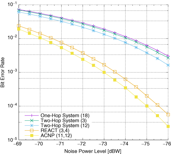
Figure 5.20 Performance comparison for ACNP.
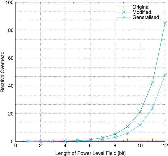
Figure 5.21 Overhead of Modified Hello message and Generalised Hello message.
As previously suggested, one could also expect increased control overhead related to the introduction of the Modified Hello message containing the Extended Link Code field. In fact, the Optimised Link State Routing protocol may typically differentiate between four distinct Link Types and three distinct Neighbour Types, giving 12 combinations and meaning that the Neighbour Interface Addresses may become assigned to 12 groups, i.e. Link Messages, at most. Taking into consideration the proposed modifications to the Optimised Link State Routing protocol, due to the type of information required by the multi-point relay station selection heuristics, as well as by the resulting Autonomic Cooperative Networking Protocol, it suffices to focus on SYM_LINK along with SYM_NEIGH and MPR_NEIGH. This would limit the number of the theoretically available 16 combinations, enlarged with the introduction of VAA_NEIGH, merely to two. Consequently, as indicated by Wódczak (2012a), the main factor influencing the overhead would clearly stem from the size of the Power Level field in question. As such, the length of this field, amounting to 12 bits, would imply that, in theory, there could be 4096 values allowed. Multiplied further by the aforementioned two combinations, this would result in 8192 possibilities. What is more, taking into account that, in the worst case, solely singular interfaces could become characterised by a given Power Level, one could expect to end up with as many as 8192 Link messages, each accompanied by a header of length 32 bits. This, of course, would be the worst option, while, as originally shown by Wódczak (2012a) and depicted in Figure 5.21, the observed overhead could be almost diminishable for as few as six bits (Wódczak, 2014a).33
5.4.3 Architectural Integration Aspects
Touching upon the architectural integration aspects once again, as well as keeping in mind all the developments rolled out in this chapter, one might expect some extensive analysis, especially taking into account the ever increasing complexity of the interaction taking place on the verge of a conceptual junction between the perpendicular or orthogonal positioned entities of both the Open Systems Interconnection Reference Model and the Generic Autonomic Network Architecture.34 Since this junction appears to be multidimensional, a few different perspectives will have to be taken to provide a sufficiently detailed insight into all the architectural aspects. In particular, on the one hand, there are all the components revolving around the multi-point relay station selection heuristics, which not only brings in the relevantly modified Optimised Link State Routing protocol along with its evolved messaging structure, but also incorporates VAA-based and DSTBC-enabled cooperative transmission using the equivalent virtual multiple-input multiple-output radio channel. On the other hand there emerges the Autonomic Cooperative Behaviour, being a tightly fused and integral part of the Autonomic Cooperative Networking Protocol, also involving the notion of ACSs, where the related Autonomic Cooperative Nodes are intended to reside. In order to provide a relevant background, first, the roots of the Autonomic Cooperative Networking Protocol will be explained, in order to move into analysis of certain necessary conceptual transitions, so that the dependencies between various routines and the architectural relations may be described.35
In investigating the roots of the Autonomic Cooperative Networking Protocol, one needs to commence the analysis with the initial solution conceived by Wódczak (2012a) under the name of the routing information enhanced algorithm for cooperative transmission (REACT). As such, REACT was intended merely to enable the performance of DSTBC-based cooperative transmission at the link layer with the aid of additional routing information, readily available at the network layer, through an integration entity in the form of multi-point relay station selection heuristics. Because of certain limitations of such an approach, a more advanced concept in the form of the extended routing information enhanced algorithm for cooperative transmission (EREACT) was introduced, along with its evolved messaging structure. In fact, this latest development was advanced enough to become elevated to yet another level with the conception of the target Autonomic Cooperative Networking Protocol, thereby becoming one of the major building blocks of the entire Autonomic Cooperative Networking Architectural Model. One should note, however, that as much as the described transition path may appear straightforwardly incremental, it also carries certain flavour of shifting the evolved concept from an approach rooted only in the Open Systems Interconnection Reference Model towards a Generic Autonomic Network Architecture driven design, as depicted in Figure 5.22. While such a perception cannot be denied, one may also claim that the Autonomic Cooperative Networking Protocol bridges both the above-mentioned ends of the transition path.
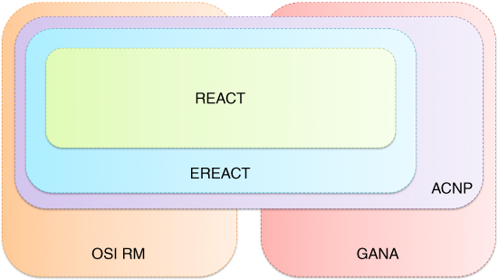
Figure 5.22 Roots of the ACNP.
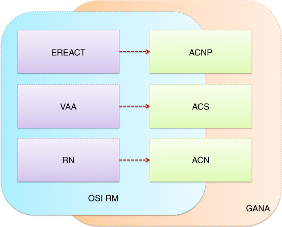
Figure 5.23 Conceptual transitions.
Whether the notion of the Autonomic Cooperative Networking Protocol should be perceived as being more of a bridging or more of a synergetic nature appears not so obvious, especially when Figure 5.23 is considered, where certain conceptual transitions are outlined. One should note that, once again, there exist backgrounds created by both the Open Systems Interconnection Reference Model and the Generic Autonomic Network Architecture, yet, despite their mutual perpendicularity or orthogonality, the present depiction should be read to way more emphasise the fact that even though the latter may stem from the former, there is by no means a full overlap between the two. Given such a context, as well as assuming the usually followed bottom-up approach to analysis, first comes the relay node which, keeping in mind the aforementioned transition path, becomes elevated to the Autonomic Cooperative Node. This upgrade should be viewed as maintaining the roots of the Open Systems Interconnection Reference Model, while adding the extra flavour brought by the Generic Autonomic Network Architecture. In fact, moving upwards, one immediately comes across a fairly similar transformation, where what was originally referred to as a VAA becomes upgraded to an ACS, intended to virtually arrange Autonomic Cooperative Nodes. Last comes the already discussed transition from EREACT towards the Autonomic Cooperative Networking Protocol related to the orchestration of the ACSs.
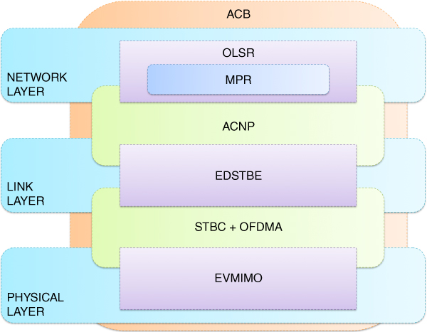
Figure 5.24 Dependencies among the physical layer, link layer, and network layer routines.
In fact, this orchestration is done under the umbrella of the Autonomic Cooperative Behaviour, whose role and scope enlarges substantially as the conceptual plot develops. In fact, attempting to make a comparison between what was outlined in the previous chapter in Figure 4.34 and what is presently proposed in Figure 5.24, one may easily discern that the changes between the link layer and the network layer are rather substantial. The discrepancy results from the fact that previously the network layer was incorporated into the global picture of the proposed design to create a fully-fledged appearance of the notion of Autonomic Cooperative Behaviour. This way it was sufficient to refer to the Optimised Link State Routing protocol only, with the multi-point relay station selection heuristics playing more the role of a gluing entity. However, once the workings of the network layer started becoming substantial in this chapter, it also became apparent that the multi-point relay station selection heuristics should be emphasised much more as an inherent element of the Optimised Link State Routing protocol, while the interaction with the EDSTBE should be performed over an interfacing entity in the form of the Autonomic Cooperative Networking Protocol. In essence, analysing the incorporation of the multi-point relay station selection heuristics into the Autonomic Cooperative Networking Protocol, one should not forget the need for an intermediary step in this respect, taking the form of EREACT (Figure 5.23).
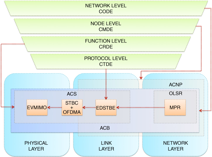
Figure 5.25 Architectural relations stemming from the link layer and function level.
Given the above context, one comes to the most fully-fledged depiction of the architectural relations stemming from the interworking of both the link layer and the function level and their adjacent entities. In particular, once again making a comparison between what was presented in the previous chapter in Figure 4.35 and what is outlined in Figure 5.25, one may clearly discern that while the former concept did not go beyond the notion of Autonomic Cooperative Behaviour, mostly due to the stage of conceptual progression on the side of the Open Systems Interconnection Reference Model itself, this time, with the introduction of the Autonomic Cooperative Networking Protocol, the entire picture of the Autonomic Cooperative Networking Architectural Model, being the ultimate enabler of the Autonomic Intelligence Evolved Cooperative Networking, has become substantially advanced. This is thanks to the fact that the mechanism of Autonomic Cooperative Behaviour, as expressed separately by many ACSs, has now become orchestrated by the CMDE at the node level. One should note, however, that the scope of Autonomic Cooperative Behaviour understood in a more general sense is by no means limited by the routines of the Autonomic Cooperative Networking Protocol. In fact, as can be seen from Figure 5.24, in the final version of the still evolving design, the Autonomic Cooperative Behaviour is supposed to interact directly with the cooperation orchestration decision element of the network level, thereby surpassing the Autonomic Cooperative Networking Protocol that it has so far been merely a part of.
5.5 Conclusion
In this chapter, first of all the workings of the experimentation-related version of the Optimised Link State Routing protocol were discussed, with special emphasis on its functional and structural characteristics related to the field of applicability and the assumed messaging structure. Apart from the proactivity-driven relevance to mobile ad hoc network scenarios, special stress was put on the multi-point relay station selection heuristics, with the incorporation of certain small alignments thereto. Additionally, the information storage repositories were scrutinised, to provide the required context for further developments and to introduce new elements in the form of the VAA selector set and its related VAA selector tuples, intended to become the enablers of the target concept of routing information enhanced cooperative transmission. What followed directly were the developments originating from the routing information enhanced algorithm for cooperative transmission, which was conceived by the author as a method for applying the additional information collected by the Optimised Link State Routing protocol inherent in the network layer, and its modified version in particular, to enable and orchestrate the cooperative transmission at the link layer. To this end the justification for the introduction of the routing information enhanced algorithm for cooperative transmission was given, with special attention paid to the relevant algorithmic description, additionally assuming certain elements and nomenclature of the Optimised Link State Routing protocol, predominantly because of the direct usage of the outcome of the multi-point relay station selection heuristics.
Then, an elevated concept in the form of the extended routing information enhanced algorithm for cooperative transmission was outlined, along with the evolved messaging structure, in order to lay the ground for the target Autonomic Cooperative Networking Protocol. In this respect, the vital topics of address auto-configuration and duplicate address detection were brought up, before the focus shifted towards the umbrella formed by the function level overlay logic. Thus the workings of the Autonomic Cooperative Networking Protocol were outlined, covering the role of the extended routing information enhanced algorithm for cooperative transmission in its conception, and also the justification of the role of the evolved messaging structure in the process of Autonomic Cooperative Node preselection, along with the layout of and the reasoning for the specific design of the routing table. Given such a context, the extended algorithmic description defining the logic of the cooperation management decision element was scrutinised in reference to what was previously outlined for the original routing information enhanced algorithm for cooperative transmission. Based on this, it became possible not only to evaluate its advantages by simulation analysis, but also to address the overhead aspects of the evolved messaging structure. Last, but not least, the entire analysis was elevated once again to be concluded with the aspects of architectural integration covering the roots of the Autonomic Cooperative Networking Protocol and involving the pertinent conceptual transitions, as well as the related dependencies among its architectural entities.
References
- Abolhasan M, Wysocki T, and Lipman J 2005 Performance investigation on three classes of MANET routing protocols. Asia-Pacific Conference on Communications, pp. 774–778.
- Adjih C, Baccelli E, and Jacquet P 2003 Link state routing in wireless ad-hoc networks. IEEE Military Communications Conference, MILCOM, pp. 13–16.
- Adjih C, Boudjit S, Jacquet P, Laouiti A, Muhlethaler P, and Mase P 2005 Address Autoconfiguration in Optimized Link State Routing Protocol. Internet-Draft.
- Alamouti S 1998 A simple transmit diversity technique for wireless communications. IEEE Journal on Selected Areas in Communications 16(8), 1451–1458.
- Andrews J, Shakkottai S, Heath R, Jindal N, Haenggi M, Berry R, Guo D, Neely M, Weber S, Jafar S, and Yener A 2008 Rethinking information theory for mobile ad hoc networks. IEEE Communications Magazine 46(12), 94–101.
- Baccelli E, Clausen T, and Garnier J 2005 OLSR Passive Duplicate Address Detection. Internet-Draft.
- Bernardos C, Calderon M, and Moustafa H 2010 Survey of IP Address Autoconfiguration Mechanisms for MANETs. Internet-Draft.
- Chessa S, Corradi A, Foschini L, and Girolami M 2016 Empowering mobile crowdsensing through social and ad hoc networking. IEEE Communications Magazine, 54(7), 108–114.
- Clausen T and Jacquet P 2003 Optimised Link State Routing Protocol (OLSR). RFC 3626.
- Clausen T, Dearlove C, Jacquet P, and Herberg U 2014 The Optimized Link State Routing Protocol Version 2. RFC 7181.
- Conti M and Giordano S 2014 Mobile ad hoc networking: Milestones, challenges, and new research directions. IEEE Communications Magazine, 52(1), 85–96.
- Doppler K, Redana S, Wódczak M, Rost P, and Wichman R 2007 Dynamic resource assignment and cooperative relaying in cellular networks: Concept and performance assessment. EURASIP Journal on Wireless Communications and Networking 2009(475281), 1–14.
- Dottling M, Mohr W, and Osseiran A 2009 Radio Technologies and Concepts for IMT-Advanced. Wiley.
- Droms R, Bound J, Volz B, Lemon T, Perkins C, and Carney M Jul. 2003 Dynamic Host Configuration Protocol for IPv6 (DHCPv6). RFC 3315.
- Mase K and Adjih C 2006 No Overhead Autoconfiguration OLSR. Internet-Draft.
- Mase K and Weniger K 2006 PDAD-OLSR: Passive Duplicate Address Detection for OLSR. Internet-Draft.
- Narten T, Nordmark E, Simpson W, and Soliman H 2007 Neighbor Discovery for IP Version 6 (IPv6). RFC 4861.
- Papadopoulos G, Kritsis K, Gallais A, Chatzimisios P, and Noel T 2016 Performance evaluation methods in ad hoc and wireless sensor networks: A literature study. IEEE Communications Magazine 54(1), 122–128.
- Plesse T, Lecomte J, Adjih C, Badel M, Jacquet P, Laouiti A, Minet P, Muhlethaler P, and Plakoo A 2004 OLSR performance measurement in a military mobile ad-hoc network. 24th International Conference on Distributed Computing Systems Workshops, pp. 704–709.
- Plummer DC 1982 An Ethernet Address Resolution Protocol. RFC 826.
- Postel J 1980 User Datagram Protocol. RFC 768.
- Qayyum A, Viennot L, and Laouiti A 2002 Multipoint relaying for flooding broadcast messages in mobile wireless networks. 35th Annual Hawaii International Conference on System Sciences, HICSS.
- Sholander P, Yankopolus A, Coccoli P, and Tabrizi S 2002 Experimental comparison of hybrid and proactive MANET routing protocols. IEEE Military Communications Conference, MILCOM, pp. 513–518.
- Szott S, Wódczak M, Chaparadza R, Meriem TB, Tsagkaris K, Kousaridas A, Radier B, Mihailovic A, Natkaniec M, Loziak K, Kosek-Szott K, and Wagrowski M 2012a Standardization of an autonomicity-enabled mesh architecture framework, from ETSI-AFI Group perspective: Work in progress (Part 1 of 2). Fourth IEEE International Workshop on Management of Emerging Networks and Services (IEEE MENS 2012) at IEEE GLOBECOM 2012, Anaheim, California, USA.
- Szott S, Wódczak M, Chaparadza R, Meriem TB, Tsagkaris K, Kousaridas A, Radier B, Mihailovic A, Natkaniec M, Loziak K, Kosek-Szott K, and Wagrowski M 2012b Standardization of an autonomicity-enabled mesh architecture framework, from ETSI-AFI Group perspective: Work in progress (Part 2 of 2). Fourth IEEE International Workshop on Management of Emerging Networks and Services (IEEE MENS 2012) at IEEE GLOBECOM 2012, Anaheim, California, USA.
- Tarokh V, Jafarkhani H, and Calderbank AR 1999 Space-time block coding for wireless communications: Performance results. IEEE Journal on Selected Areas in Communications 17(3), 451–460.
- Thomson S, Narten T, and Jinmei T 2007 IPv6 Stateless Address Autoconfiguration. RFC 4862.
- Villasenor-Gonzalez L, Ge Y, and Lament L 2005 HOLSR: A hierarchical proactive routing mechanism for mobile ad hoc networks. IEEE Communications Magazine 43(7), 118–125.
- Wódczak M 2006 On Routing information Enhanced Algorithm for space-time coded Cooperative Transmission in wireless mobile networks. PhD thesis Faculty of Electrical Engineering, Institute of Electronics and Telecommunications, Poznań University of Technology, Poland.
- Wódczak M 2007 Extended REACT: Routing information Enhanced Algorithm for Cooperative Transmission. 16th IST Mobile & Wireless Communications Summit 2007, Budapest, Hungary.
- Wódczak M 2010 Future autonomic cooperative networks. Second International ICST Conference on Mobile Networks and Management, Santander, Spain.
- Wódczak M 2011a Aspects of cross-layer design in autonomic cooperative networking. IEEE Third International Workshop on Cross Layer Design, Rennes, France.
- Wódczak M 2011b Autonomic cooperation in ad-hoc environments. Fifth International Workshop on Localised Algorithms and Protocols for Wireless Sensor Networks (LOCALGOS) in conjunction with IEEE International Conference on Distributed Computing in Sensor Systems (DCOSS), Barcelona, Spain.
- Wódczak M 2011c Autonomic cooperative networking for wireless green sensor systems. International Journal of Sensor Networks (IJSNet) 10(1–2), 83–93.
- Wódczak M 2011d Convergence aspects of autonomic cooperative networking. IEEE Fifth International Conference on Next Generation Mobile Applications, Services and Technologies, Cardiff, Wales, UK.
- Wódczak M 2012a Autonomic Cooperative Networking. Springer.
- Wódczak M 2012b Optimised link state routing protocol as enabler of cooperative transmission for emergency communications. Eighth IEEE International Symposium on Instrumentation and Control Technology (IEEE ISICT), University of Westminster in London, UK.
- Wódczak M 2012c Simulation environment for autonomic cooperative networking in indoor scenario. 14th International Conference on Modelling and Simulation (UKSim).
- Wódczak M 2014a Autonomic Computing Enabled Cooperative Networked Design. Springer.
- Wódczak M 2014b Autonomic Cooperative Behaviour enabled emergency system design. The Mediterranean Journal of Computers and Networks, 10(1).
- Wódczak M 2014c Autonomic cooperative networking. In Encyclopaedia of Information Science and Technology, third edition, ed. Khosrow-Pour, M. IGI Global.
- Wódczak M 2017 Autonomic cooperative communications. In Encyclopaedia of Information Science and Technology, fourth edition, ed. Khosrow-Pour, M. IGI Global.
- Younis O, Kant L, Chang K, Young K, and C G 2009 Cognitive MANET design for mission-critical networks. IEEE Communications Magazine 47(10), 64–71.
- Younis O, Kant L, McAuley A, Manousakis K, Shallcross D, Sinkar K, Chang K, Young K, Graff C, and Patel M 2010 Cognitive tactical network models. IEEE Communications Magazine 48(10), 70–77.
- Zheng YR and Xiao C 2003 Simulation models with correct statistical properties for Rayleigh fading channels. IEEE Transactions on Communications 51(6), 920–928.