
Load balancers are used to support scaling and high availability for applications and services. A load balancer is primarily composed of three components—a frontend, a backend, and routing rules. Requests coming to the frontend of a load balancer are distributed based on routing rules to the backend, where we place multiple instances of a service. This can be used for performance-related reasons, where we would like to distribute traffic equally between endpoints in the backend, or for high availability, where multiple instances of services are used to increase the chances that at least one endpoint will be available at all times.
We will cover the following recipes in this chapter:
- Creating an internal load balancer
- Creating a public load balancer
- Creating a backend pool
- Creating health probes
- Creating load balancer rules
- Creating inbound NAT rules
- Creating explicit outbound rules
Technical requirements
For this chapter, an Azure subscription is required.
The code samples can be found at https://github.com/PacktPublishing/Azure-Networking-Cookbook-Second-Edition/tree/master/Chapter10.
Creating an internal load balancer
Microsoft Azure supports two types of load balancers—internal and public. An internal load balancer is assigned a private IP address (from the address range of subnets in the virtual network) for a frontend IP address, and it targets the private IP addresses of our services (usually, an Azure virtual machine (VM)) in the backend. An internal load balancer is usually used by services that are not internet-facing and are accessed only from within our virtual network.
Getting ready
Before you start, open the browser and go to the Azure portal via https://portal.azure.com.
How to do it...
In order to create a new internal load balancer with the Azure portal, we must use the following steps:
- In the Azure portal, select Create a resource and choose Load Balancer under Networking services (or search for Load Balancer in the search bar).
- In the new pane, we must select a Subscription option and a Resource group option for where the load balancer is to be created. Then, we must provide information for the Name, Region, Type, and SKU options. In this case, we select Internal for Type to deploy an internal load balancer and set SKU to Standard. Finally, we must select the Virtual network and the Subnet that the load balancer will be associated with, along with information about the IP address assignment, which can be Static or Dynamic:
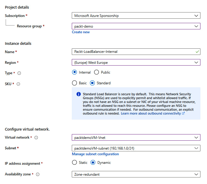
Figure 10.1: Creating a new internal load balancer
- After all the information is entered, we select the Review + create option to validate the information and start the deployment of the load balancer.
How it works...
An internal load balancer is assigned a private IP address, and all requests coming to the frontend of an internal load balancer must come to that private address. This limits the traffic coming to the load balancer to be from within the virtual network associated with the load balancer. Traffic can come from other networks (other virtual networks or local networks) if there is some kind of virtual private network (VPN) in place. The traffic coming to the frontend of the internal load balancer will be distributed across the endpoints in the backend of the load balancer. Internal load balancers are usually used for services that are not placed in a demilitarized zone (DMZ) (and are therefore not accessible over the internet), but rather in middle- or back-tier services in a multi-tier application architecture.
We also need to keep in mind the differences between the Basic and Standard SKUs. The main difference is in performance (this is better in the Standard SKU) and SLA (Standard has an SLA guaranteeing 99.99% availability, while Basic has no SLA). Also, note that Standard SKU requires a Network Security Group (NSG). If an NSG is not present on the subnet or Network Interface, or NIC (of the VM in the backend), traffic will not be allowed to reach its target. For more information on load balancer SKUs, see https://docs.microsoft.com/azure/load-balancer/skus.
Creating a public load balancer
The second type of load balancer in Azure is a public load balancer. The main difference is that a public load balancer is assigned a public IP address in the frontend, and all requests come over the internet. The requests are then distributed to the endpoints in the backend.
Getting ready
Before you start, open the browser and go to the Azure portal via https://portal.azure.com.
How to do it...
In order to create a new public load balancer with the Azure portal, we must follow these steps:
- In the Azure portal, select Create a resource and choose Load Balancer under Networking services (or search for Load Balancer in the search bar).
- In the new pane, we must select a Subscription option and a Resource group option for where the load balancer is to be created. Then, we must provide information for Name, Region, Type, and SKU. In this case, we select Public for Type to deploy a public load balancer. and set SKU to Standard. Selecting Public as the load balancer type will slightly change the pane. We will no longer have the option to select a virtual network and subnet, as we did for the internal load balancer. Instead, we can choose options for Public IP address (new or existing), Public IP address SKU, IP address assignment, and whether we want to use IPv6. Note that the public IP address SKU depends directly on the load balancer SKU, so the SKU selected for the load balancer will transfer automatically to the IP address:
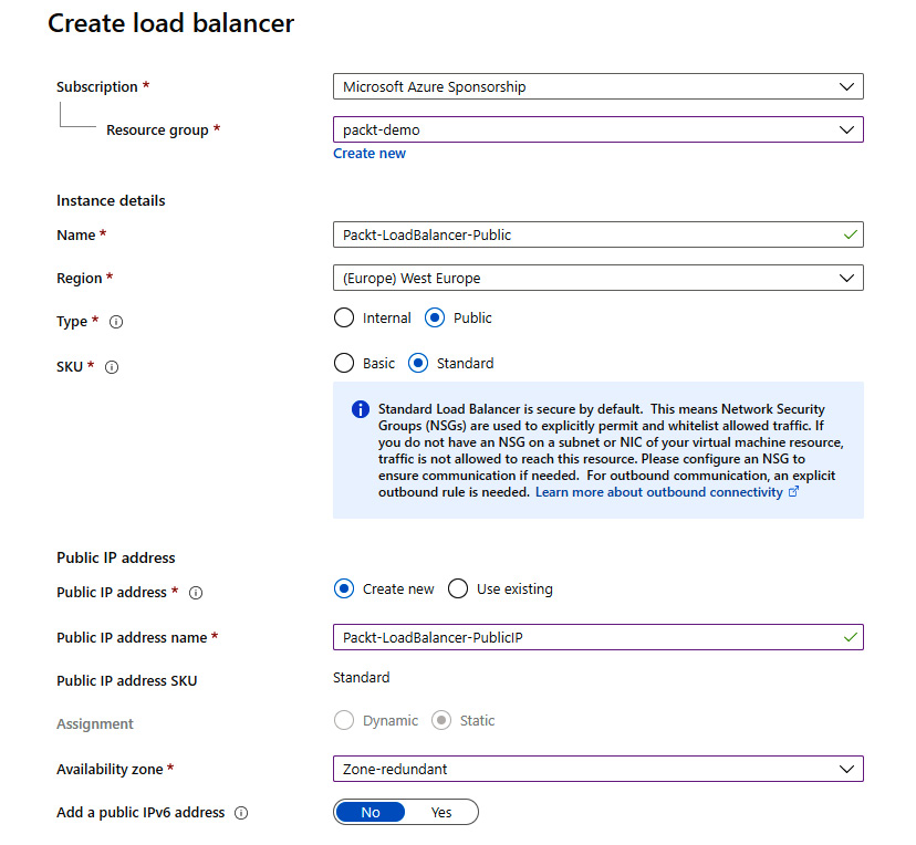
Figure 10.2: Creating a new public load balancer
- After all the information is entered, select the Review + create option to validate the information and start the deployment of the load balancer.
How it works...
The public load balancer is assigned a public IP address in the frontend. Therefore, all requests coming to the public load balancer will come over the internet, targeting the load balancer's public IP address. Requests are then distributed to endpoints in the backend of the load balancer. What's interesting is that the public load balancer does not target the public IP addresses in the backend, but private IP addresses instead. For example, let's say that we have one public load balancer with two Azure VMs in the backend. Traffic coming to the public IP address of the load balancer will then be distributed to VMs but will target the VMs' private IP addresses.
Public load balancers are used for public-facing services, most commonly for web servers.
Creating a backend pool
After the load balancer is created, either internally or publicly, we need to configure it further in order to start using it. During the creation process, we define the frontend of the load balancer and know where traffic needs to go to reach the load balancer. But, in order to define where that traffic needs to go after reaching the load balancer, we must first define a backend pool.
Getting ready
Before you start, open the browser and go to the Azure portal via https://portal.azure.com.
How to do it...
In order to create the backend pool, we must do the following:
- In the Azure portal, locate the previously created load balancer (either internal or public).
- In the Load balancer pane, under Settings, select Backend pools. Select Add to add the new backend pool:
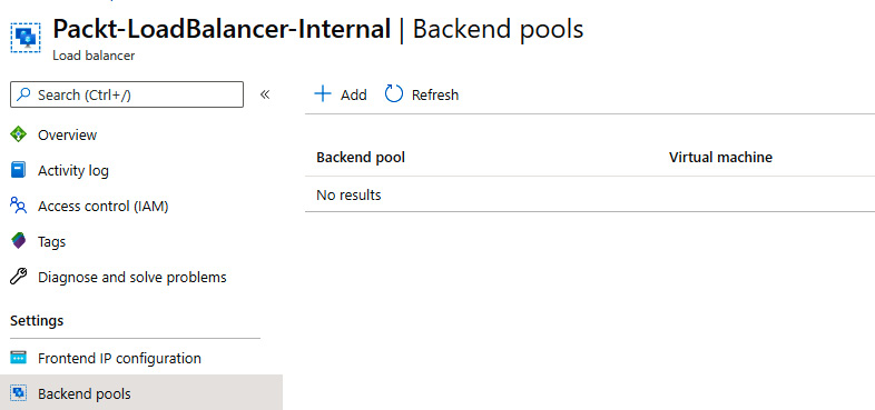
Figure 10.3: Adding a new backend pool
- In the new pane, we must provide a Name and specify what the load balancer is associated to. Associations can be created for VMs or VM scale sets. In this example, we will use Virtual machines. Based on this selection, you will be offered additional options to add VMs to the backend pool:

Figure 10.4: Additional information for adding the backend pool
- Click Add and a new pane will open. Here we can add the VMs we want to associate with the backend pool. Note that the VMs must be in the same virtual network as the load balancer and in the same availability set. Select the VMs that you want to add to the backend pool:
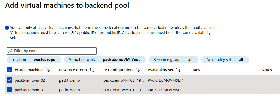
Figure 10.5: Adding VMs to the backend pool
- After the VMs are selected, they will appear under the Virtual machines list for creating the pool. Click Add to create the backend pool with the associated VMs:
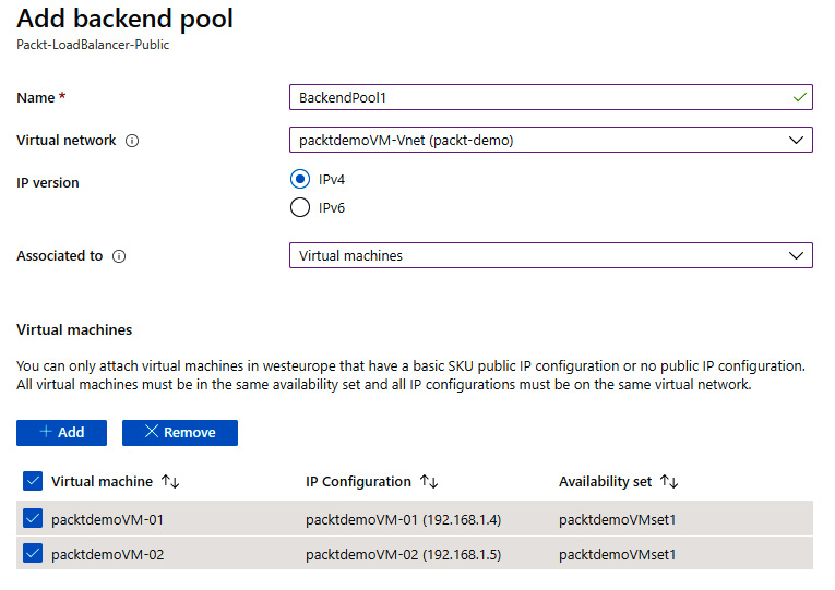
Figure 10.6: List of VMs for creating a backend pool
- After the configuration is entered, it takes a few minutes to create the backend pool. After that, the associated resources will show up in the backend pool list:

Figure 10.7: The backend pool list
How it works...
The two main components of any load balancer are the frontend and the backend. The frontend defines the endpoint of the load balancer, and the backend defines where the traffic needs to go after reaching the load balancer. As the frontend information is created along with the load balancer, we must define the backend ourselves, after which the traffic will be evenly distributed across endpoints in the backend. The available options for the backend pool are VMs and VM scale sets.
See also
More information on VMs, availability sets, and VM scale sets is available in my book, Hands-On Cloud Administration in Azure, published by Packt at https://www.packtpub.com/virtualization-and-cloud/hands-cloud-administration-azure.
Creating health probes
After the frontend and the backend of the load balancer are defined, traffic is evenly distributed among endpoints in the backend. But what if one of the endpoints is unavailable? In that case, some of the requests will fail until we detect the issue, or even fail indefinitely should the issue remain undetected. The load balancer would send a request to all the defined endpoints in the backend pool and the request would fail when directed to an unavailable server.
This is why we introduce the next two components in the load balancer—health probes and rules. These components are used to detect issues and define what to do when issues are detected.
Health probes constantly monitor all endpoints defined in the backend pool and detect if any of them become unavailable. They do this by sending a probe in the configured protocol and listening for a response. If an HTTP probe is configured, an HTTP 200 OK response is required to be considered successful.
Getting ready
Before you start, open the browser and go to the Azure portal via https://portal.azure.com.
How to do it...
To create a new health probe in the load balancer, we must do the following:
- In the Azure portal, locate the previously created load balancer (either internal or public).
- In the Load balancer pane, under Settings, select Health probes. Select Add to add a new health probe:
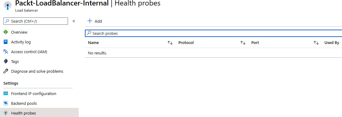
Figure 10.8: Adding a new health probe
- In the new pane, we need to provide information about the health probe's Name and IP version, or Protocol, we want to use, as well as configuring the Port, Interval, and Unhealthy threshold options, as shown in Figure 10.9:
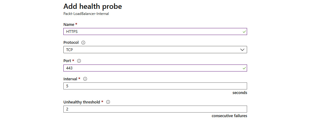
Figure 10.9: Providing health probe information
- After we select OK, the new health probe will be created and will appear on the list of available health probes associated with the load balancer.
How it works...
After we define the health probe, it will be used to monitor the endpoints in the backend pool. We define the protocol and the port as useful information that will provide information regarding whether the service we are using is available or not. Monitoring the state of the server would not be enough, as it could be misleading. For example, the server could be running and available, but the IIS or SQL server that we use might be down. So, the protocol and the port will detect changes in the service that we are interested in and not only whether the server is running. The interval defines how often a check is performed, and the unhealthy threshold defines after how many consecutive fails the endpoint is declared unavailable.
Creating load balancer rules
The last piece of the puzzle when speaking of Azure load balancers is the rule. Rules finally tie all things together and define which health probe (there can be more than one) will monitor which backend pool (more than one can be available). Furthermore, rules enable port mapping from the frontend of a load balancer to the backend pool, defining how ports relate and how incoming traffic is forwarded to the backend.
Getting ready
Before you start, open your browser and go to the Azure portal via https://portal.azure.com.
How to do it...
In order to create a load balancer rule, we must do the following:
- In the Azure portal, locate the previously created load balancer (either internal or public).
- In the Load balancer pane, under Settings, select Load balancing rules. Select Add to add a load balancing rule:
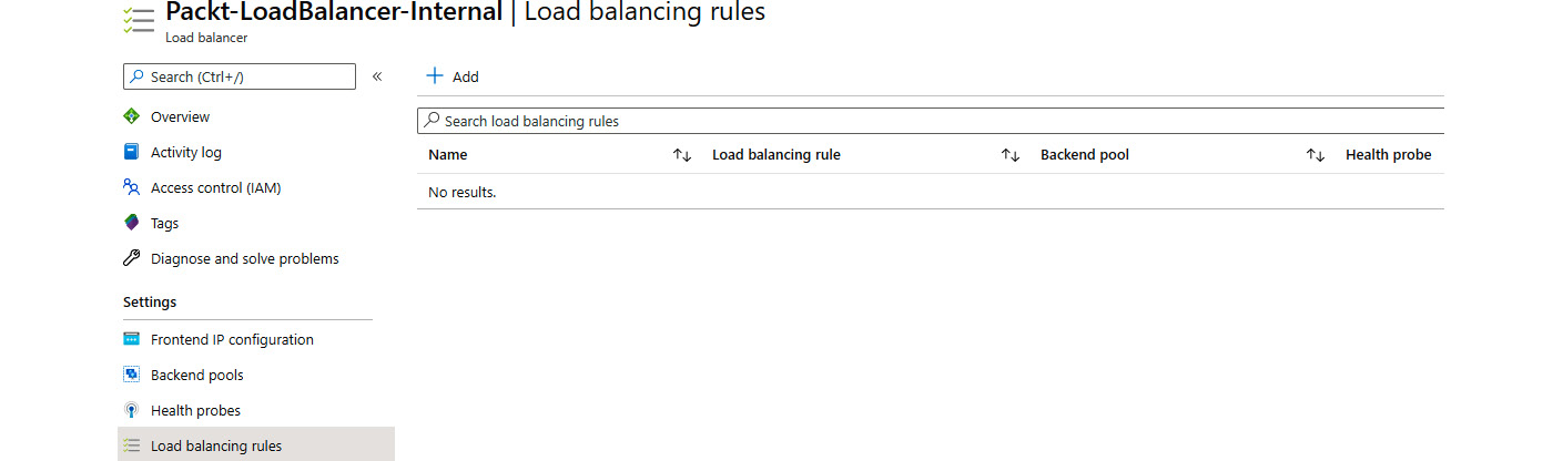
Figure 10.10: Adding load balancing rules
- In the new pane, we must provide information for the Name and the IP version we are going to use, which Frontend IP address we are going to use (as a load balancer can have more than one), the Protocol, and the Port mapping (traffic from the incoming port will be forwarded to the backend port). If we enable high-availability ports (only available on internal load balancers), this will remove the protocol options and enable load balancing on all ports for TCP and UDP protocols. Furthermore, we need to provide information for the Backend Port, Backend pool, Health probe, Session persistence, and Idle timeout (minutes) settings, and decide whether we want to use a Floating IP. Finally, we have the option to create an implicit outbound rule:
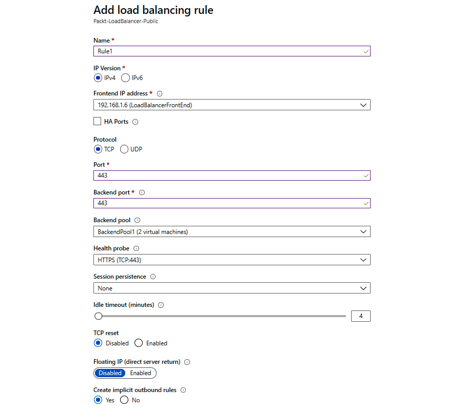
Figure 10.11: Configuring load balancing rules
- After we select OK, a new rule will be created, which will appear on the list of available load balancing rules.
How it works...
The load balancer rule is the final piece that ties all the components together. We define which frontend IP address is used and which backend the pool traffic will be forwarded to. The health probe is assigned to monitor the endpoints in the backend pool and to keep track of whether there are any unresponsive endpoints. We also create a port mapping that will determine which protocol and port the load balancer will listen on and, when the traffic arrives, where this traffic will be forwarded.
As its default distribution mode, Azure Load Balancer uses a five-tuple hash (source IP, source port, destination IP, destination port, and protocol type). If we change the session persistence to Client IP, the distribution will be two-tuple (requests from the same client IP address will be handled by the same VM). Changing session persistence to Client IP and protocol will change the distribution to three-tuple (requests from the same client IP address and protocol combination will be handled by the same VM).
Creating inbound NAT rules
Inbound Network Address Translation (NAT) rules are an optional setting in Azure Load Balancer. These rules essentially create another port mapping from the frontend to the backend, forwarding traffic from a specific port on the frontend to a specific port in the backend. The difference between inbound NAT rules and port mapping in load balancer rules is that inbound NAT rules apply to direct forwarding to a VM, whereas load balancer rules forward traffic to a backend pool.
Getting ready
Before you start, open the browser and go to the Azure portal via https://portal.azure.com.
How to do it...
In order to create a new inbound NAT rule, we must do the following:
- In the Azure portal, locate the previously created load balancer (either internal or public).
- In the Load balancer pane, under Settings, select Inbound NAT rules. Select Add to add a new inbound NAT rule:
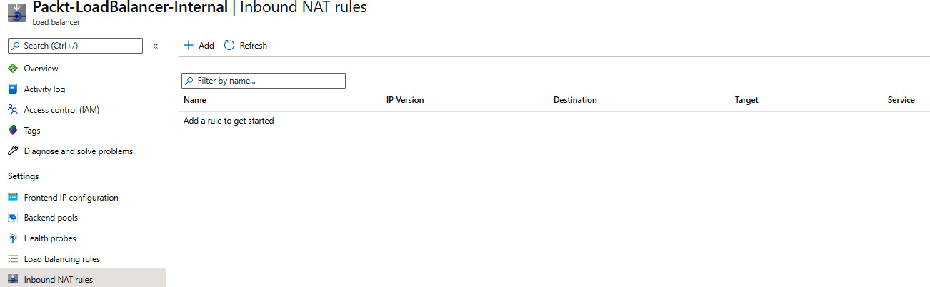
Figure 10.12: Adding an inbound NAT rule for an existing load balancer
- In the new pane, we must provide details for the Name, Frontend IP address, IP Version (set based on the frontend IP address), Service, Protocol, and Port fields. We can also edit Idle timeout, which is set to 4 minutes by default. Select Target virtual machine and Network IP configuration for the same machine (if the VM has more than one IP configuration). Finally, you can select the default port mapping or use a custom one:
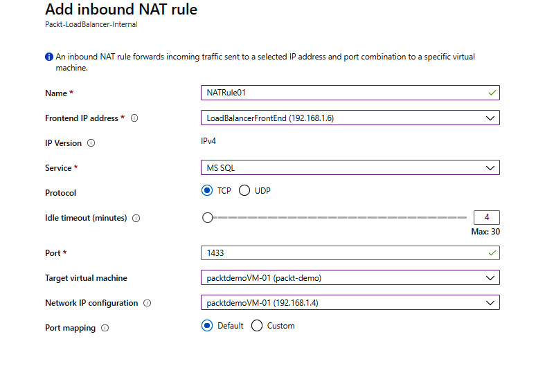
Figure 10.13: Configuring the inbound NAT rule settings
- After we select OK, a new inbound NAT rule will be created.
How it works...
Inbound NAT rules enable you to use the public IP of the load balancer to connect directly to a specific backend instance. They create a port mapping similar to the port mapping created by load balancer rules but to a specific backend instance. A load balancer rule creates additional settings, such as the health probe or session persistence. Inbound NAT rules exclude these settings and create unconditional mapping from the frontend to the backend. With an inbound NAT rule, forwarded traffic will always reach the single server in the backend, whereas a load balancer will forward traffic to the backend pool and will use a pseudo-round-robin algorithm to route traffic to any of the healthy servers in the backend pool.
Creating explicit outbound rules
When creating load balancing rules, we can create implicit outbound rules. This will enable Source Network Address Translation (SNAT) for VMs in the backend pool and allow them to access the internet over the load balancer's public IP address (specified in the rule). But in some scenarios, implicit rules are not enough and we need to create explicit outbound rules. Explicit outbound rules (and SNAT in general) are available only for public load balancers with the Standard SKU.
Getting ready
Before we begin, make sure that implicit outbound rules are disabled from load balancing rules:

Figure 10.14: Disabling implicit outbound rules
Now, open the browser and go to the Azure portal via https://portal.azure.com.
How to do it...
In order to create a load balancer rule, we must do the following:
- In the Azure portal, locate the previously created public load balancer.
- In the Load balancer pane, under Settings, select Outbound rules. Select Add to add the load balancing rule:
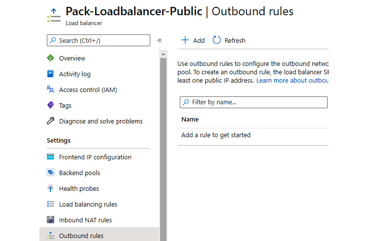
Figure 10.15: Adding outbound rules
- In the Outbound rules pane, we must provide the rule name and select options for the Frontend IP address, Protocol (All, TCP, or UDP), Idle timeout, TCP reset, and Backend pool fields. In the Port allocation section of the same pane, we must select options for Port allocation, Outbound ports, Ports per instance (disabled when the maximum number of backend instances is selected), and Maximum number of backend instances:

Figure 10.16: The outbound rule pane
How it works...
Outbound rules depend on three things—frontend IP addresses, instances in the backend pool, and connections. Each frontend IP address has a limited number of ports for connections. The more IP addresses are assigned to the frontend, the more connections are allowed. On the other hand, the number of connections allowed (per backend instance) decreases with the number of instances in the backend.
If we set the default number of outbound ports, allocation is done automatically and without control. If we have a VM scale set with the default number of instances, port allocation will be done automatically for each VM in the scale set. If the number of instances in a scale set increases, this means that the number of ports allocated to each VM will drop in turn.
To avoid this, we can set port allocation to manual and either limit the number of instances that are allowed or limit the number of ports per instance. This will ensure that each VM has a certain number of ports dedicated and that connections will not be dropped.