5
Loadbearing Walls
A wall is a continuous, usually vertical, structure that is thin relative to its length and height. The prime function of an external wall is to provide shelter against wind, rain and the daily and seasonal variations of outside temperature normal to its location, for reasonable indoor comfort. To provide adequate shelter, a wall should have sufficient strength and stability to be self‐supporting, and also to support roofs and upper floors. Internal walls divide space into smaller areas, rooms and compartments. To differentiate the structural requirements of those walls that carry the loads from roofs and upper floors in addition to their own weight from those that are free standing and carry only their own weight, the terms ‘loadbearing’ and ‘non‐loadbearing’ are used. The majority of walls for single‐, double‐ and triple‐storey buildings are constructed with loadbearing masonry walls, or are framed from timber, steel or concrete. The type of walling materials used will generally depend on the availability of materials and labour, economic factors and design considerations. This chapter describes the main principles of wall construction. The focus is on loadbearing walls common in domestic and small‐scale developments. Details of timber, steel and concrete framed construction, and the materials used for the building envelopes to framed buildings, are described in Barry’s Advanced Construction of Buildings.
5.1 Functional requirements
The function of a wall is to enclose and protect a building or to divide space within a building. A wide variety of materials are used to construct walls, ranging from the familiar stone, brick and block, timber, concrete, glass and steel, through to the less common straw bale and earth construction and various hybrid systems. Regardless of the materials used, the commonly accepted functional requirements of a wall are:
- Strength and stability
- Resistance to weather and ground moisture
- Durability and freedom from maintenance
- Fire safety
- Resistance to the passage of heat
- Resistance to airborne and impact sound
- Security
- Aesthetics
Strength and stability
The strength of the materials used in wall construction is determined by the strength of a material in resisting compressive and tensile stress and the way in which the materials are put together. The compressive strength of brick and stone combined with the durability, fire resistance and appearance of the materials makes masonry an attractive choice for many designers and builders. In the majority of small buildings, such as houses, the compressive strength of brick and stone is rarely fully utilised because the functional requirements of stability and exclusion of weather dictate a thickness of wall in excess of that required for strength alone. The guidance given in the Approved Document for walls of brick or block is based on compressive strengths of 5 N/mm2 for bricks and 2.8 N/mm2 for blocks for walls up to two storeys in height where the storey height is not more than 2.7 m, and 7 N/mm2 for bricks and blocks for walls of three‐storey buildings where the storey height is greater than 2.7 m.
Wall stability may be affected by foundation movement, eccentric loading, lateral forces (wind loading), and expansion and contraction due to changes in temperature and moisture. Eccentric loads (those not acting on the centre of the wall), such as from floors and roofs, and lateral forces, such as wind, tend to deform and overturn walls. The greater the eccentricity of the loads and the greater the lateral forces, the greater the tendency of a wall to deform, bow out of the vertical and lose stability. To prevent loss of stability due to deformation under load, building regulations and codes have set limits to the height or thickness ratios (slenderness ratios) to provide reasonable stiffness against loss of stability.
Height and width
The maximum height of residential buildings is given as 15 m from the lowest ground level to the highest point of any wall or roof in Approved Document A (Figure 5.1). Height is separately defined, for example, as from the base of a gable and external wall to half the height of the gable. The height of single‐storey, non‐residential buildings is given as 3 m from the ground to the top of the roof, which limits the guidance to very small buildings. The least width of residential buildings is limited to not less than half the height. A diagram limits the dimensions of the wing of a residential building.
Figure 5.1 Maximum height and minimum width of walls for residential buildings.
(Source: Approved Document A).
Figure 5.2 Structural walls and maximum floor area.
(Source: Approved Document A).
One further limitation is that no floor enclosed by structural walls on all sides should exceed 70 m2, and a floor without a structural wall on one side, 30 m2 (Figure 5.2). As the maximum allowable length of wall between buttressing walls, piers or chimneys is given as 12 m, and the maximum span for floors as 6 m, the limitation is in effect a floor some 12 × 6 m on plan.
Thickness of walls
The general limitation of wall thickness given for stability is that solid walls of brick or block should be at least as thick as 1/16th of the storey height. This is a limiting slenderness ratio relating thickness of wall to height, measured between floors and the floor and roof, that provides lateral support and gives stability up the height of the wall. The minimum thickness of external, compartment and separating walls is given in a table in Approved Document A, relating thickness to height and length of wall, as illustrated in Figure 5.3. Compartment walls are those that are formed to limit the spread of fire, and separating walls (party walls) are those that separate adjoining buildings, such as the walls between terraced houses. Cavity walls should have leaves at least 90 mm thick, and the cavity should be at least 50 mm wide.
Internal loadbearing walls, except compartment and separating walls, should be half the thickness of external walls, as illustrated in Figure 5.3, minus 5 mm, except for the wall in the lowest storey of a three‐storey building, which should be of the same thickness, or 140 mm, whichever is the greater.
Figure 5.3 Minimum thickness of walls.
Lateral support
To provide stiffness against deformation under load, lateral (horizontal) restraint is provided by the walls, floors and roofs that are tied to the wall, together with intersecting walls and piers that are bonded or tied to the wall (see Table 5.1). Irregular profile walls have greater stiffness against deformation than straight walls because of the buttressing effect of the angle of the walls, as illustrated in Figure 5.4. The more pronounced the chevron, zigzag, offset or serpentine of the wall, the stiffer it will be. The size and number of openings in walls will also influence the stability of the wall.
Table 5.1 Lateral support for walls
Source: Taken from Approved Document A (table 11). The Building Regulations.
| Wall type | Wall length | Lateral support required |
| Solid or cavity: external compartment separating | Any length | Roof lateral support by every roof forming a junction with the supported wall |
| Greater than 3 m | Floor lateral support by every floor forming a junction with the supported wall | |
| Internal loadbearing wall (not being a compartment or separating wall) | Any length | Roof or floor lateral support at the top of each storey |
Figure 5.4 Irregular profile walls.
To provide lateral support to gable end walls, to roofs pitched at more than 15°, a system of galvanised steel straps is used. Straps of 30 × 5 mm are screwed to the underside of timber noggings fixed between three rafters, as illustrated in Figure 5.5, with timber packing pieces between the rafter next to the gable and the wall. The straps should be used at a maximum of 2 m centres and turned down against the cavity face of the inner leaf of a whole building block or down into a solid wall. To provide stability along the length and at the ends of loadbearing walls, there should be walls, piers or chimneys bonded to the wall at intervals of not more than 12 m, to buttress and stabilise the wall.
Figure 5.5 Lateral support to gable ends.
The maximum spacing of buttressing walls, piers and chimneys is measured from the centre line of the supports, as illustrated in Figure 5.6. The maximum length between piers and buttress walls is 3 m. The minimum length of a return buttressing wall should be equal to one‐sixth of the height of the supported wall. To be effective as buttresses to walls, the return walls, piers and chimneys must be solidly bonded to the supported wall.
Figure 5.6 Length of walls.
Chases in walls (cuts and rebates in walls)
To limit the effect of chases cut into walls in reducing strength or stability, vertical chases should not be deeper than one‐third of the thickness of solid walls, or a leaf of a cavity wall and horizontal chases not deeper than 1/16th. A chase is a recess, cut or built into a wall, inside which small service pipes are run.
Resistance to weather and ground moisture
Walls must adequately resist the passage of moisture, both vapour and liquid, to the inside of the building. Moisture may penetrate a wall by absorption of water from the ground that is in contact with the foundations, or through rain and snow falling on the wall. Impermeable materials are used to form damp‐proof courses (DPCs) in walls to prevent water from rising up the walls (discussed later). The ability of a wall to resist the passage of water to its inside face depends on its exposure to wind‐driven rain and the construction of the wall. Most building stone is impervious to moisture and forms a good defence against moisture penetration. Bricks will absorb a small amount of moisture, which is why solid wall construction often relies on tile hanging or rendering to protect the wall from moisture penetration.
The exposure of a wall is determined by its location and the extent to which it is protected by surrounding higher ground, or sheltered by surrounding buildings or trees, from rain driven by the prevailing winds. In the UK, the prevailing westerly winds from the Atlantic Ocean cause more severe exposure to driving rain along the west coast of the country than do the cooler and drier easterly winds on the east coast. Local knowledge and specific physical site characteristics (e.g. detailing and weathering of neighbouring buildings) are also valuable indicators of exposure.
Durability and freedom from maintenance
The durability of a wall is indicated by the frequency and extent of the work necessary to maintain minimum functional requirements and an acceptable appearance. Sound natural stone is highly durable as a walling material and will have a useful life of many years in buildings that are adequately maintained. Granite, for example, is resistant to all usual weathering agents, including highly polluted atmospheres, and will maintain a high natural polished surface for 100 years or more. Clay and concrete bricks are also highly durable. It is likely that the mortar joint between stone or brick will need some degree of repair long before the walling materials are in need of maintenance.
Fire safety
Walls (combined with doors and windows) are an important element in providing fire protection to a building. The two principal considerations are the structural integrity of the wall in a fire and the surface spread of flame, which are determined by the materials used to construct the walls.
Specifying a minimum period of fire resistance for the elements of the structure, for example, the walls, helps to prevent premature failure in a fire. The requirements are that the elements should resist collapse for a minimum period of time, during which the occupants may escape in the event of fire. Periods of fire resistance vary from 30 minutes upwards, depending on the type of building and its height. Natural stone, brickwork and blockwork are incombustible and will not support or encourage the spread of flame across its surface. Care is required to ensure that applied finishes to walls do not compromise the integrity of fire resistance.
Resistance to the passage of heat
Walls need to provide adequate thermal resistance to heat loss and, for a short period in the summer, to heat gain. This is achieved through the mass and thickness of the wall and/or the inclusion of thermal insulation material(s) to the wall assembly. The natural stones and bricks used for walling are poor insulators against the transfer of heat and will contribute little to the thermal resistance in a wall. It is necessary to use materials with a low U‐value in conjunction with masonry to achieve the required thermal insulation values. This is discussed in further detail later in the chapter, in relation to solid wall construction and cavity wall construction.
Resistance to the passage of sound
The most effective insulation against airborne sound is a dense barrier such as a solid wall of stone or brick, which absorbs the energy of the airborne sound waves. The heavier and more dense the material of the wall, the more effective it tends to be in reducing sound. The Building Regulations require walls and floors to provide reasonable resistance to airborne sound between dwellings and between machine rooms, tank rooms, refuse chutes and habitable rooms. Resistance to impact sound will consist of absorbent material, such as cork, that will act to cushion the impact, or serve to interrupt the path of the sound. Noise generated in a room may be reflected from the walls and ceilings and build up to an uncomfortable intensity inside the room, particularly where the wall and ceiling surfaces are hard and smooth. To prevent the build‐up of reflected sound, absorbent material may be applied to walls and ceilings, such as acoustic tiles or soft materials, to absorb the energy of the sound waves.
Security
Walls, in conjunction with doors, windows and roofs, help to provide a secure enclosure. In domestic properties, unauthorised entry to property usually takes place through doors or windows. In commercial premises, especially where buildings contain goods that are subject to theft, it is not unusual for forced entry to occur through walls and roofs. Therefore, the resistance of the wall to, for example, ram‐raiding may be a primary function of the wall.
Aesthetics
Walls are a major component in the design of a building, making a significant contribution to the aesthetic character of the building. Choice of materials will be dependent on satisfying the functional and performance requirements listed earlier and on satisfying the client’s and designer’s aesthetic goals. The choice of stone and bricks, combined with external renders and slate hanging, provides designers with a wide choice of external finishes. Other considerations will relate to site context, such as the walling materials used on neighbouring buildings and specific requirements of the local planning authority. The desired appearance of the walls may also influence whether loadbearing or framed construction is chosen.
5.2 Walling materials
A variety of materials may be used for constructing loadbearing walls. The most common are stone, reconstructed stone, bricks and blocks, which are described here. Other materials such as straw and unfired earth bricks are discussed later.
Stone
Stone has a long history of use in the UK, being used for a variety of building types, depending on proximity of location to local stone quarries and fashion. Natural stone is more expensive as compared to bricks, and therefore is mainly used as a facing material bonded or fixed to a backing of brickwork or concrete. Many of the larger civic and commercial buildings are faced with natural stone because of its durability, texture, colour and sense of permanence. Natural stone is also used as the outer leaf of cavity walls for houses (both loadbearing and framed construction) in areas where local quarries can supply stone at reasonable cost. Much of the time‐consuming labour associated with cutting, shaping and finishing natural stone has been reduced by the use of power tools. Reconstituted stone products have been developed as cheaper alternatives to natural stone and are manufactured to have similar properties as natural stone.
Natural stone
The natural stones used in building may be classified by reference to their origin as: (1) igneous, such as granite and basalt; (2) sedimentary, such as limestones and sandstones; and (3) metamorphic, such as slates and marble. Natural stone has been used in the construction of buildings because it was thought that any hard, natural stone would resist the action of wind and rain for centuries. Many natural stones have proved to be extremely durable for 100 years or more; however, there have been some failures due to the poor selection of the material, poor workmanship and/or poor detailing. Variation within the stone may cause localised weathering problems on exposure to rain and chemical pollutants in the air.
Some natural stones are comparatively soft and moist when first quarried but will gradually harden. Building stones should be seasoned (allowed to harden) for periods of up to a few years, depending on their size and type. Natural stones that are stratified, such as limestone and sandstone, must be used so that they lie on their natural bed to support compressive stress.
The strength of building stone lies in its very considerable compressive strength. The ultimate or failing stress of stone used for walling is about 300–100 N/mm3 for granite, 195–27 N/mm3 for sandstone and 42–16 N/mm3 for limestone. The use of stone as a facing material makes little use of the inherent compressive strength of the material.
Reconstituted (reconstructed) stone
Reconstructed stone is made from an aggregate of crushed stone, cement and water. The stone is crushed so that the maximum size of the particles is 6 mm, and it is mixed with cement in the proportions of one part cement to three or four parts of stone. Portland cement, white cement or coloured cement may be used to simulate the colour of a natural stone as closely as possible. A comparatively dry mix of cement, crushed stone and water is prepared and cast in moulds. The mix is thoroughly consolidated inside the moulds by vibrating and is left to harden in the moulds for at least 24 hours. The stones are then taken out of the moulds and allowed to harden gradually for 28 days.
Reconstructed stone has much the same texture and colour as the natural stone from which it is made, and can be cut, carved and dressed just like natural stone. It is not stratified, is free from flaws and is sometimes a better material than the natural stone from which it is made. Moulded cast stones made by repetitive casting can often be produced more cheaply than similar natural stones, which have to be cut and shaped.
A cheaper form of cast stone is made with a core of ordinary concrete, faced with an aggregate of crushed natural stone and cement. This material should more properly be called ‘cast concrete’. The core is made from clean gravel, sand and cement, and the facing is made from crushed stone and cement to resemble the texture and colour of a natural stone. The crushed stone, cement and water is first spread in the base of the mould to a thickness of about 25 mm, the core concrete is added and the mix consolidated. If the stone is to be exposed on two or more faces, the natural stone mix is spread up the sides and the bottom of the mould. This type of cast stone cannot be carved as it has only a thin surface of natural‐looking stone.
Bricks and brickwork
The word ‘brick’ is used to describe a small block of burnt clay of such size that it can be conveniently held in one hand, and it is slightly longer than twice its width. The great majority of bricks in use today are made from clay, although bricks can also be made from sand and lime or concrete. Unfired clay bricks may also be used for internal walls and external walls that are protected from moisture. Glass bricks and blocks are also widely available. In the UK, the standard brick size is 215 × 102.5 × 65 mm, as illustrated in Figure 5.7. With a 10‐mm mortar joint, the working size becomes 225 × 112.5 × 75 mm. Bricks may be manufactured to other shapes and sizes, and are usually known as ‘specials’.
Clay bricks
Clay differs quite widely in composition from place to place, and the clay dug from one part of a field may differ from that dug from another part of the same field. Clay is ground in mills, mixed with water to make it plastic and then moulded, either by hand or machine, to the shape and size of a brick. Bricks that are shaped and pressed by hand in a sanded wood mould and then dried and fired have a sandy texture, are irregular in shape and colour, and are used as facing bricks due to the variety of their shapes, colour and texture. Machine‐made bricks are either hydraulically pressed in steel moulds or extruded as a continuous band of clay. The continuous band of clay, a section of which is the length and width of a brick, is cut into bricks using a wire frame. Bricks made this way are called ‘wire cuts’. The moulded brick is baked to dry out the water and is burnt at a high temperature so that part of the clay fuses the whole mass of the brick into a hard, durable unit. Because there is wide variation in the composition of the clays suitable for brickmaking, and because it is possible to burn bricks over quite a wide range of temperatures sufficient to fuse the material into a durable mass, a large variety of bricks is available.


Figure 5.7 Types of brick.
Calcium silicate (sand–lime) bricks
Calcium silicate bricks are generally known as ‘sand–lime bricks’. The bricks are made from a carefully controlled mixture of clean sand and hydrated lime, which is mixed together with water, moulded to brick shape and then hardened in a steam oven. The resulting bricks are very uniform in shape and colour and are normally a dull white. Coloured sand–lime bricks are made by adding a colouring matter during manufacture. The material from which they are made can be carefully selected and accurately proportioned to ensure a uniform hardness, shape and durability that are quite impossible with the clay used for most bricks.
Concrete bricks
Concrete bricks are manufactured in the same size as clay bricks. They tend to be more consistent in shape, size and colour than clay bricks, and come in a variety of colours and finishes. Appearance and properties vary between manufacturers, although the concrete brick does have a different appearance from clay bricks, which extends the choice available.
Brick classifications
Bricks may be classified in accordance with their uses as noted in the following text, although they should be specified according to the required performance requirements – that is, strength, thermal performance, water absorption, frost resistance and so on.
- Commons. These are bricks that are sufficiently hard to safely carry the loads normally supported by brickwork, but are used for situations where they will not be exposed to view, owing to their dull texture or poor colour.
- Facings. This includes any brick that is sufficiently hard‐burnt to carry normal loads. Manufacturers offer an extensive range of colours and textures from which to choose.
- Engineering bricks. These are bricks that have been made from selected clay and carefully burnt to make a very solid and hard brick that is capable of safely carrying much heavier loads than other types of bricks. These bricks are mainly used for walls carrying exceptionally heavy loads, brick piers, general engineering works and especially for works below ground.
- Special bricks. Specials are made for specific uses in fairface brickwork. (The word ‘fairface’ describes a brick wall finished with a reasonably flat and level face for the sake of appearance.) These bricks are made from fine clays to control and reduce shrinkage deformation during firing. Figure 5.8 is an illustration of some typical (standard) specials. Some specials may be available from stock, others will need to be made to order.
- Special specials. Manufacturers also make purpose‐made specials to order, known as ‘special specials’, to suit particular design requirements. Additional time will be needed to design and manufacture the special specials, and this will need to be considered in the planning of the construction works.

Figure 5.8 Special bricks.
Physical properties of bricks
When specifying bricks, a performance specification will need to consider the following parameters: size and type, compressive strength, frost resistance, water absorption and suction, soluble salt content and visual appearance. This information is provided by brick manufacturers. It is common practice to specify facing bricks by name (manufacturer and brick name), which will automatically confirm the brick’s characteristics.
- Compressive strength. The compressive strength of bricks is found by crushing 12 of them individually until they fail or crumble. The average compressive strength of the brick is stated as the newton per millimetre of surface area (N/mm2) required to ultimately crush the brick. The crushing resistance varies from about 3.5 N/mm2 for soft facing bricks up to 140 N/mm2 for engineering bricks.
- Water absorption and suction. The amount of water a brick will absorb is a guide to its density and therefore its strength in resisting crushing. The level of water absorption is most critical for bricks to be used for DPCs or below DPC level. Absorption rates vary between 1% and 35%. Bricks with high suction rates absorb water rapidly from the mortar, and hence they are more difficult to reposition as work proceeds than bricks with medium to low suction rates.
- Thermal and moisture movement. All building materials move as a result of the expansion and contraction caused by temperature or moisture changes. The amount of movement depends on the materials and conditions. Allowance must be made for movement in masonry walls through careful positioning of control joints (Table 5.2). Brick manufacturers offer guidance based on current standards. Photograph 5.1 shows a movement joint in a brick and flint clad wall. Expansion in long walls without adequate control joints may result in the bricks at the end of the wall oversailing the DPC (Figure 5.9), or the corner of walls cracking (Figure 5.10). Where buildings or different structures meet, it is always advisable to have control or movement joints. Photograph 5.2 shows a movement joint at the junction between two properties, which forms a party wall between the dwellings.
Table 5.2 Thermal and moisture movement joints in brickwork
| Brick type | Type of movement | Recommended distance between joints (mm) |
| Clay fired bricks | Expansion | 12 |
| Calcium silicate bricks | Shrinkage | 7.5–9 |
| Concrete blocks or bricks | Shrinkage | 6 |

Photograph 5.1 Movement joint.

Figure 5.9 Elevation of a wall: expansion of brickwork causing oversailing.
Figure 5.10 Plan of a wall junction: expansion and shrinkage at the corner joint.
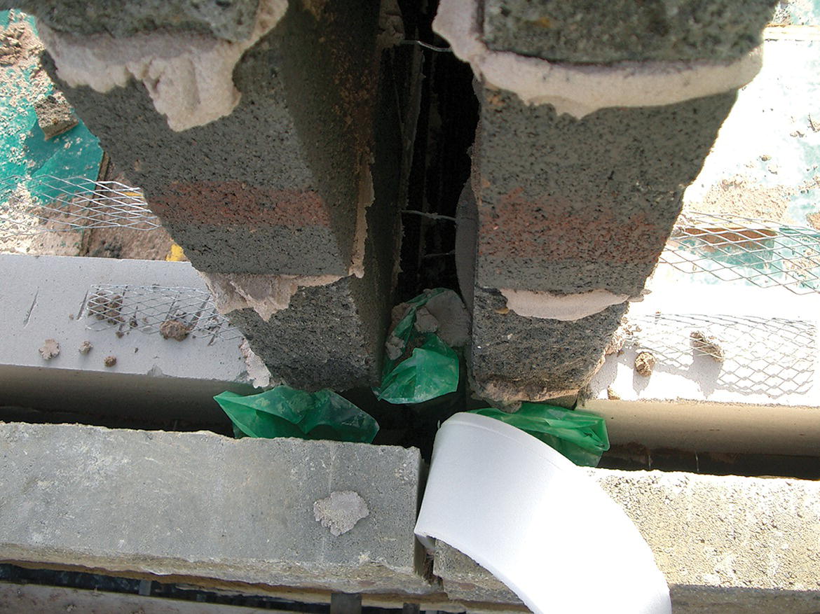
Photograph 5.2 Brickwork movement joint and fire stop at a party wall junction.
For clay bricks, it is recommended that the joint be capable of accommodating 10 mm movement. Because materials will be used to construct and fill the joint, this may mean that the joint will be 12–20 mm wide. Calcium silicate bricks suffer from contraction rather than expansion. Where joints are used to accommodate shrinkage, the wall should be structurally sound when the joint is at its widest (when the wall has shrunk to its full extent). Control joints should be located where there is lateral support (Figure 5.11).
Figure 5.11 Lateral stability across control joints.
Extra ties at 300‐mm centres should be used on each side of the joint. Wire and plastic wall ties can accommodate differential movement between the skins of cavity walls by bending and flexing. In some situations, it may be necessary to place a wall tie directly across the movement joint. Specially designed sleeves can be used with straight wall ties: these allow for movement along the length of the ties but resist movement in other directions (Figure 5.12).

Figure 5.12 Lateral stability across control joints provided by ties with sleeves.
- Movement due to differential settlement. Where it is anticipated that differential settlement may occur due to different ground conditions, foundation designs or building loads, control joints should be used to allow separate parts of the building to move without causing cracking to the facing or structural elements. In long buildings or terraced housing, it may be necessary to separate the buildings and incorporate control joints that allow for differential settlement while retaining the appearance of the building.
- Appearance. There is a large range of bricks from which to choose, and choice is often made on personal preference for the colour and texture of the brick, assuming it meets the set performance requirements. Choice is also influenced by the bricks used on neighbouring buildings, local town planning authority requirements and the existing bricks when working on repair and alteration works.
- Frost resistance. If bricks are saturated and the water within them freezes (expanding as it freezes up to −4 °C), it is likely that small cracks will develop, causing the face of the brickwork to break away (Photograph 5.3). Care is required in exposed areas – for example, parapet walls, chimney stacks and around DPCs – in relation to the selection of bricks and the detailing of the respective junctions to ensure durability. With increased emphasis on higher thermal standards and thermally upgrading existing buildings, the additional insulation results in less heat passing through the wall. During the winter months, this means that the masonry, which is directly exposed to the external environment, receives less heat energy from the interior of the building, and as such is more susceptible to damage from frost. Hence, the durability of the masonry needs careful consideration, especially in exposed locations.
- Efflorescence. Clay bricks contain soluble salts that migrate, in solution in water, to the surface of brickwork as water evaporates to outside air. These salts will collect on the face of brickwork as an efflorescence of white crystals that appear in irregular, unsightly patches. This efflorescence of white salts is most pronounced in parapet walls, chimneys and below DPCs, where brickwork is most liable to saturation. The concentration of salts depends on the soluble salt content of the bricks and the degree and persistence of saturation of brickwork. The efflorescence of white salts on the surface is unsightly and usually causes no damage. In time, the salts may be washed away from surfaces by rain. Heavy concentration of salts can cause spalling and powdering of the surface of bricks, particularly those with smooth faces. This effect is sometimes described as ‘crypto‐efflorescence’. The salts trapped behind the smooth face of bricks expand when wetted by rain and cause the face of the bricks to crumble and disintegrate. Efflorescence may also be caused by the absorption of soluble salts from a cement‐rich mortar or from the ground. There is no way of preventing the absorption of soluble salts from the ground by brickwork below the horizontal DPC level, although the effect can be reduced considerably by the use of dense bricks below the DPC. Soluble salts can migrate through mortar and natural stone in the same way as a brick wall.
Photograph 5.3 Face of brickwork removed by frost attack.
When brickwork is persistently wet – such as in foundations, retaining walls, parapets and chimneys – sulphates in bricks and mortar may in time crystallise and expand, causing mortar and renderings to disintegrate. To minimise this effect, bricks with low sulphate content should be used.
Blockwork
Building blocks are wall units, larger in size than a brick, that can be handled by one person. Building blocks are usually made of concrete or clay.
Concrete blocks
These are used extensively for both loadbearing and non‐loadbearing walls. A concrete block wall can be laid in less time than a similar brick wall. Lightweight aggregate concrete blocks have good insulating properties against the transfer of heat and are used for the inner leaf of cavity walls. Concrete blocks may be used as a fairface external wall finish. Blocks are accurately moulded to uniform sizes and are made from aggregates to provide a variety of colours and textures.
Concrete blocks are manufactured from cement and either dense or lightweight aggregates as solid, cellular or hollow blocks, as illustrated in Figure 5.13. A cellular block has one or more holes or cavities that do not pass wholly through the block, and a hollow block is one in which the holes pass through the block. The thicker blocks are made with cavities or holes to reduce weight and drying shrinkage.
The most commonly used size of both dense and lightweight concrete blocks is 440 mm long × 215 mm high. The height of the block is chosen to coincide with three courses of bricks for the convenience of building in wall ties and bonding to brickwork. The length of the block is chosen for laying in stretcher bond. For the leaves of cavity walls and internal loadbearing walls, 100‐mm‐thick blocks are used. For non‐loadbearing partition walls, 75‐mm‐thick lightweight aggregate blocks are used. Either 440 × 215 mm or 390 × 190 mm blocks may be used. Concrete blocks may be specified by their minimum average compressive strength for:
- All blocks not less than 75 mm thick
- All blocks less than 75 mm thick used for non‐loadbearing walls, which should be specified by transverse strength

Figure 5.13 Concrete blocks.
The usual compressive strengths for blocks are 2.8, 3.5, 5, 7, 10, 15, 20 and 35 N/mm2. The compressive strength of blocks used for the walls of small buildings of up to three storeys, recommended in Approved Document A, is between 2.8 and 7 N/mm2, depending on the loads carried. Concrete blocks may also be classified in accordance with the aggregate used in making the block and some common uses.
Dense aggregate blocks for general use
The blocks are made of cement, natural aggregate or blast‐furnace slag. The usual mix is one part of cement to six or eight parts of aggregate by volume. These blocks are as heavy per cubic metre as bricks, they are not good thermal insulators and their strength in resisting crushing is less than that of most well‐burnt bricks. The colour and texture of these blocks is far from attractive, and they are usually covered with plaster or a coat of rendering. These blocks are used for internal and external loadbearing walls, including walls below ground.
Lightweight aggregate concrete blocks for general use in building
The blocks are made of cement, and one of the following lightweight aggregates: granulated blast‐furnace slag, foamed blast‐furnace slag, expanded clay or shale, or well‐burnt furnace clinker. The usual mix is one part cement to six or eight of aggregate by volume.
Lightweight aggregate concrete blocks are used primarily for internal non‐loadbearing walls. These blocks, usually 75 or 100 mm thick, are made with the same lightweight aggregate as those in Class 2. These blocks are manufactured as solid, hollow or cellular, depending largely on the thickness of the block. The thin blocks are solid and either square‐edged or with a tongue and groove in the short edges, so that there is a mechanical bond between blocks to improve the stability of internal partitions. The poor structural stability may be improved by the use of storey‐height door linings, which are secured at floor and ceiling levels. Thin block internal partitions afford negligible acoustic insulation and poor support for fittings, such as bookshelves secured to them. The thicker blocks are either hollow or cellular to reduce weight and drying shrinkage.
As water dries out from precast concrete blocks, the shrinkage that occurs, particularly with lightweight blocks, may cause serious cracking of the plaster and rendering applied to the surface of a wall built with them. Obviously, the wetter the blocks, the more they will shrink. It is essential that these blocks be protected on building sites from saturation by rain, both when they are stacked on site before use and while walls are being built.
Clay blocks
Hollow clay building blocks are made from selected brick clays that are press moulded and burnt. These hard, dense blocks are hollow to reduce shrinkage during firing, and also to reduce their weight. They are grooved to provide a key for plaster, as illustrated in Figure 5.14. The standard block is 290 mm long × 215 mm high, and 75, 100 or 150 mm thick. Clay blocks are comparatively lightweight, do not suffer moisture movement and have good resistance to damage by fire and poor thermal insulating properties. In the UK, these blocks are mainly used for non‐loadbearing partitions. They are extensively used in southern Europe as infill panel walls to framed buildings, where the tradition is to render the external face of buildings on which the blocks provide a substantial mechanical key for rendering.
Figure 5.14 Clay blocks.
Interlocking and recycled blocks
A number of manufacturers have developed interlocking block systems that provide improved thermal resistance as compared to traditional construction. Products tend to be based on polystyrene – or similar materials, such as recycled wood – that forms a lightweight, hollow block. The blocks are interlinked and tied together, usually with uPVC ties, and then filed with a material such as concrete to provide the necessary strength and stability to the wall. These systems tend to appeal to self‐builders and small developers because of their simplicity and ease of construction. The hollow block acts as a type of permanent or lost formwork, with the advantage of providing good thermal insulation. Reinforcement can be inserted between the blocks used to provide additional tensile strength when required. These systems rely on a render to the external face, or the application of some form of facing to provide additional weather protection and an aesthetically pleasing finish.
5.3 Mortar
A material is required that helps to bind the various walling units, be they bricks, blocks or stones, into a coherent whole. This is achieved by using a cement or lime mortar. The basic requirements of mortar are that it should harden to such an extent that it can carry the weight normally carried by masonry without crushing, and that it should be sufficiently plastic when laid to accommodate the varying sizes of bricks, blocks and stone. The mortar should also be sufficiently hard as to resist the weathering action of rain, snow and frost.
Mortar is a mixture of sand, water and a matrix. Sand is classified as either ‘soft’ or ‘hard’. Sand that is not washed and which contains some clay in it feels soft and smooth when held in the hand, and hence the term ‘soft sand’. Sand that is clean feels coarse in the hand, and hence the term ‘sharp’. These are terms used by bricklayers. When soft sand (‘builders’ sand’) is used, the mortar is very smooth and plastic, and it is much easier to spread and to bed the bricks in, as compared to mortar made of sharp sand.
The material required to bind the grains of sand together into a solid mass is termed the ‘matrix’, and two materials can be used for this purpose: either lime or cement. Lime, which mixes freely with water and sand, produces a material that is smooth, plastic and easily spread. Portland cement produces a hard, dense material that has more than adequate strength for use as mortar, and is largely unaffected by damp conditions. A mortar in which the advantages of lime and cement are combined is termed ‘compo’ mortar.
Types of mortar
Cement mortar
When fine cement powder is mixed with water, a chemical action takes place between the water and cement. At the completion of this reaction, the nature of the cement has so changed that it binds itself very firmly to most materials. As the reaction takes place, the excess water evaporates, leaving the cement and sand to harden gradually into a solid mass. The hardening of the mortar becomes noticeable some few hours after mixing, and is complete in a few days. The usual mix of cement and sand for mortar is from one part cement to three or four parts sand, to one part cement to eight parts of sand by volume, mixed with just sufficient water to render the mixture plastic. A mortar of cement and sand is very durable and is often used for brickwork below ground level and brickwork exposed to weather above roof level, such as parapet walls and chimney stacks. When used with some types of bricks, it can cause efflorescence. Because cement mortar has greater compressive strength than required for most ordinary brickwork, and because it is not very plastic by itself, it is sometimes mixed with lime and sand.
Lime mortar
Lime is manufactured by burning limestone or chalk, and the result of this burning is an off‐white, lumpy material known as ‘quicklime’. When quicklime is mixed with water, a chemical change occurs, during which heat is generated, and the lime expands to about three times its former bulk. This change is gradual, taking some days to complete, and the quicklime afterwards is said to be ‘slaked’ – that is, it has no more thirst for water; or, more precisely, the lime is said to be ‘hydrated’. Lime for building is delivered to site ready‐slaked, and is termed ‘hydrated lime’. When mixed with water, lime combines chemically with carbon dioxide in the air, and it gradually hardens into a solid mass in undergoing this change, which firmly binds the sand. The particular advantage of lime is that it is a cheap, reusable, readily available material that produces a plastic material ideal for bedding bricks and stone. Its disadvantages are that it is a messy, laborious material to mix, and it gains strength slower than cement. Because it is, to some extent, soluble in water, it will lose its adhesive property in persistently damp situations, crumble and eventually fall out of joints. Protected from dampness, lime mortar will serve as an effective mortar for the life of most buildings. Lime mortar is usually mixed with one part of lime to three parts of sand by volume. The mortar is plastic, easy to spread and hardens into a dense mass of good compressive strength. Although lime mortar has been replaced with cement mortar in most new building projects, it is essential for maintenance work in historic buildings.
Hydraulic lime
Hydraulic lime is made by burning a mixture of chalk or limestone that contains clay. Hydraulic lime is stronger than ordinary lime and will harden in wet conditions – hence the name. Ordinary Portland cement, made from similar materials and burnt at a higher temperature, has largely replaced hydraulic lime.
Ready‐mixed mortar
Ready‐mixed mortars have come into use particularly on sites where extensive areas of brickwork are laid. A wide range of lime and sand, lime cement and sand, and cement and sand mixes is available. The sand may be selected to provide a colour and texture, or the mix may be pigmented for the same reason. Lime mortar is delivered to site ready to use within the day of delivery. Cement mix and cement lime mortar are delivered to site ready‐mixed with a retarding admixture. The retarding admixture is added to cement mix mortars to delay the initial set of cement. The initial set of ordinary Portland cement occurs some 30 minutes after the cement is mixed with water, so that an initial hardening occurs to assist in stiffening the material for use as rendering on vertical surfaces, for example. The advantages of ready‐mixed mortar are consistency of the mix, the wide range of mixes available, saving in site labour costs and reduction in wastage of material, which is common with site mixing.
Proportions by volume
Mortar for general brickwork may be made from a mixture of cement, lime and sand, in the proportions set out in Table 5.3. These mixtures combine the strength of cement with the plasticity of lime, have much the same porosity as most bricks and do not cause efflorescence on the face of the brickwork. The mixes set out in Table 5.3 are tabulated from rich mixes (1) to weak mixes (5). A rich mix of mortar is one in which there is a high proportion of matrix – that is, lime or cement or both – to sand, as in the 1:0:3 mix, and a weak mix is one in which there is a low proportion of lime or cement to sand, as in the 1:3:12 mix. The richer the mix of mortar, the greater its compressive strength; and the weaker the mix, the greater the ability of the mortar to accommodate moisture or temperature movements. The general uses of the mortar mixes given in Table 5.3 are as mortar for brickwork or blockwork, as follows:
- Mix 1: for cills, copings and retaining walls
- Mix 2: parapets and chimneys
- Mix 3: walls below DPC
- Mix 4: walls above DPC
- Mix 5: internal walls and lightweight block inner leaf of cavity
Table 5.3 Mortar mixes
Source: Taken from BS 5628: Part 3:1985 (table 15).
| Air‐entrained mixes | |||
| Mortar designation | Cement:lime:sand | Masonry cement:sand | Cement:sand with plasticiser |
| 1 | 1 : 0 to ¼: 3 | ||
| 2 | 1 : ½ : 4 to 4½ | 1 : 2½ to 3½ | 1 : 3 to 4 |
| 3 | 1 : 1 : 5 to 6 | 1 : 4 to 5 | 1 : 5 to 6 |
| 4 | 1 : 2 : 8 to 9 | 1 : 5½ to 6½ | 1 : 7 to 8 |
| 5 | 1 : 3 : 10 to 12 | 1 : 6½ to 7 | 1 : 8 |
Mortar plasticisers
Liquids known as ‘mortar plasticisers’, when added to water, effervesce. If very small quantities are added to mortar, when it is mixed, the millions of minute bubbles that form surround the hard, sharp particles of sand, and so make the mortar plastic and easy to spread. The specific application of these mortar plasticisers is that, if used with cement mortar, they increase its plasticity, and there is no need to use lime. It seems that the plasticisers do not adversely affect the hardness and durability of the mortar, and hence they are commonly and successfully used in mortars.
Jointing
‘Jointing’ is the word used to describe the finish of the mortar joints between bricks or blocks, in brickwork or blockwork that is finished fairface (not subsequently covered with plaster, rendering or other finish). Flush joints are generally made as a ‘bagged’ or a ‘bagged in’ joint. The joint is made by rubbing coarse sacking or a brush across the face of the brickwork to rub away all protruding mortar, and hence leave a flush joint. This type of joint, illustrated in Figure 5.15, can most effectively be used on brickwork in which the bricks are uniform in shape and comparatively smooth faced, where the mortar will not spread over the face of the brickwork.
A bucket handle joint is a concave, slightly recessed joint, as illustrated in Figure 5.15. A bucket handle joint may be formed by a jointing tool with or without a wheel attachment to facilitate running the tool along uniformly deep joints. The advantage of the bucket handle joint is that the operation compacts the mortar into the joint and improves weather resistance to some extent. Flush and bucket handle joints are mainly used for jointing as the brickwork is raised, the joint being made after the mortar has hardened sufficiently, or ‘gone off’.
The struck and recessed joints shown in Figure 5.15 are more laborious to make, and therefore more expensive. The struck joint is made with a pointing trowel that is run along the joint either along the edges of uniformly shaped bricks or along a wood straight edge, where the bricks are irregular in shape or coarse textured, to form the splayed back joint. The recessed joint is similarly formed with a tool shaped for the purpose. Of the joints described, the struck joint is mainly used for pointing the joints in old brickwork, and the recessed joint to emphasise the profile, colour and textures of bricks for appearance’s sake to both new and old brickwork.

Figure 5.15 Jointing and pointing.
Pointing
‘Pointing’ is the operation of filling mortar joints with a mortar selected for colour and texture to either brickwork or blockwork. Mortar for pointing is a special mix of lime, cement and sand (or stone dust), chosen to produce a particular effect of colour and texture. The overall appearance of a fairface brick wall can be altered by the selection of mortar colour and type of pointing. The joints in new brickwork are raked out about 20 mm deep when the mortar has gone off sufficiently and before it has set hard, and the joints are pointed as scaffolding is removed.
The mortar joints in old brickwork that was laid in lime mortar may, in time, crumble and be worn away by the action of wind and rain. The joints are raked out to a depth of about 20 mm and pointed with a mortar mix of cement, lime and sand that has roughly the same density as the brickwork. The operation of raking out joints is laborious and messy, and the job of filling the joints with mortar for pointing is time consuming; hence, the pointing of old work is expensive. Pointing or re‐pointing old brickwork is carried out both as protection for the old lime mortar to improve weather resistance and to improve the visual appearance of a wall.
5.4 Bonding bricks and blocks
When building a wall, it is usual to lay bricks in regular, horizontal courses, so that each brick bears on two bricks below. The bricks are said to be ‘bonded’, since they bind together by being laid across each other along the length of the wall, as illustrated in Figure 5.16. The advantage of bonding is that the wall acts as a whole, so that the load of a beam carried by the topmost brick is spread to the two bricks below it, then to the three below that and so on down to the base or foundation course of bricks. The failure of one poor‐quality brick such as ‘A’ in a wall, as shown in Figure 5.16, and a slight settlement under part of the foundation such as ‘B’ and ‘C’, will not affect the strength and stability of the whole wall, as the load carried by the weak brick and the two foundation bricks is transferred to the adjacent bricks. Because of the bond, window and door openings may be formed in a wall, the load of the wall above the opening being transferred to the brickwork on each side of the openings by an arch or lintel. The effect of bonding is to stiffen a wall along its length, and also, to some small extent, against lateral pressure, such as wind.

Figure 5.16 Bricks stacked in pyramid fashion.
Types of bond
Stretcher bond
The four faces of a brick, which may be exposed in fairface brickwork, are the two long stretcher faces and the two header faces, as illustrated in Figure 5.17. The face on which the brick is laid is the ‘bed’. Some bricks have an indent or ‘frog’ formed in one of the bed faces. The purpose of the frog or indent is to assist in compressing the wet clay during moulding. The frog also serves as a reservoir of mortar onto which bricks in the course above may more easily be bedded.
Figure 5.17 Brick faces.
Brick length can vary appreciably, especially those that are hand moulded and those made from plastic clays that will shrink differentially during firing. It was common practice to describe the thickness of a wall by the length of a brick – that is, ½ B, 1 B, 11/2 B or 2 B walls – rather than by using a precise dimension (the walls in Figures 5.18 and 5.19 may be described as ‘1/2 B thick walls’, and the walls in Figure 5.20 as ‘1 B thick walls’). This convention is used in this book too; however, dimensions should always be specified to avoid any possible confusion.
The external leaf of a cavity wall is often built of brick. The most straightforward way of laying bricks in the outer leaf of a cavity wall is with the stretcher face of each brick showing externally. To ensure that bricks are bonded along the length of the wall, they are laid with the vertical joints between bricks lying directly under and over the centre of the bricks in the courses under and over. This is described as ‘stretcher bond’, as illustrated in Figure 5.18.

Figure 5.18 Stretcher bond.
Figure 5.19 Flemish bond with snap headers.
Figure 5.20 (a) Header bond; (b) Flemish bond; (c) English bond.
At the intersection of two half‐brick walls at corners or angles and at the jambs, the bricks are laid so that a header face shows in every other course to complete the bond, as illustrated in Figure 5.18. The appearance of a wall laid in a stretcher bond may be somewhat monotonous because of the mass of stretcher faces showing. To provide some variety, the wall may be built with snap headers, so that a stretcher face and a header face show alternately in each course, with the centre of the header face lying directly under and over the centre of the stretcher faces in courses below and above, as illustrated in Figure 5.19. This form of fake Flemish bond is achieved by using half‐bricks, and hence the name ‘snap header’. The combination and variety in colour and shape can add appreciably to the appearance of a wall. The additional labour and likely wastage of bricks add somewhat to the cost.
English and Flemish bonds
A solid wall, 1 B and thicker, is bonded along its length and through its thickness. The two basic ways in which a solid brick wall may be bonded are with every brick showing a header face and each header face lying directly over two header faces below, or with header faces centrally over a stretcher face in the course below. A bond in which only header faces show is termed a ‘heading’ or ‘header’ bond. This bond is little used, as the great number of vertical joints and header faces is generally considered unattractive. A bond in which header faces lie directly above and below a stretcher face is termed the ‘Flemish bond’ (Figure 5.20b). This bond is generally considered the most attractive bond for facing brickwork, because of the variety of colour shades between header and stretcher faces dispersed over the whole face of the walling.
The English bond, illustrated in Figure 5.20c, avoids the repetition of header faces in each course by using alternate courses of header and stretcher faces, with a header face lying directly over the centre of a stretcher face below. The colour of header faces may differ from the colour of stretcher faces. In the English bond, this difference is shown in successive horizontal courses.
Bonding at angles and jambs
At the end of a wall at a stop end, at an angle or quoin and at jambs of openings, the bonding of bricks has to be finished up to a vertical angle. A brick ¼ B wide has to be used to close or complete the bond of the ¼ B overlap of face brickwork. A brick, cut in half along its length, is used to close the bond at an angle. This cut brick is termed a ‘queen closer’, and is illustrated in Figure 5.21. If the narrow‐width queen closer is laid at the angle, it might be displaced during bricklaying. To avoid this possibility, the closer is laid next to a header, as illustrated in Figure 5.22. The rule is that a closer should be laid next to a quoin (corner) header.

Figure 5.21 Queen closer.
There is often an appreciable difference in the length of facing bricks, so that a solid wall 1 B thick may be difficult to finish as a fairface wall on both sides. Where a 1 B wall is built with bricks of uneven length, it may be necessary to select bricks of the same length as headers and use longer bricks as stretchers. Walls 11/2 B thick may be used for substantial walling for larger buildings where the walling is finished fairface on both sides.
Figure 5.22 (a) Double Flemish bond; (b) English bond.
To complete the bond of a solid wall 11/2 B thick in double Flemish bond, it is necessary to use cut half‐bricks in the thickness of the wall, as illustrated in Figure 5.22a. At angles and stop ends of a wall, queen closers are laid next to quoin headers, and a three‐quarter‐length cut brick is used. Cutting half‐length (1/2 bats) and three‐quarter‐length bricks and closers is time consuming and wasteful. A 11/2 B–thick wall, finished fairface on both sides and showing English bond on both sides, requires considerably less cutting of bricks to complete the bond, as illustrated in Figure 5.22b. It is only necessary to cut closers and three‐quarter‐length bricks to complete the bond at angles and stop ends.
Garden wall bond
Garden wall bonds are designed specifically to reduce the number of through headers to minimise the labour in selecting bricks of roughly the same length for use as headers. Usual garden wall bonds are three courses of stretchers to every course of headers in an English garden wall bond and one header to every three stretchers in Flemish garden wall bond, as illustrated in Figure 5.23. The reduction in the number of through headers does, to an extent, weaken the through bond of the brickwork. Other combinations such as two or four stretchers to one header may be used. Tops of garden walls are finished with special coping bricks, or a brick or stone capping or coping, to provide weather protection to the top of the wall.
Figure 5.23 Garden wall bonds.
Bonding blocks
Blocks are made in various thicknesses to suit most wall requirements, and are usually laid in stretcher bond. Thin blocks, used for non‐loadbearing partitions, are laid in running stretcher bond, with each block centred over and under blocks above and below. At return angles, full blocks bond into the return wall in every other course, as illustrated in Figure 5.24. To ensure that the full‐width bonding of blocks at angles is not disturbed, for the sake of stability, a short length of cut block is used as a closer and infill block. Thicker blocks are laid in off‐centre running bond, with a three‐quarter‐length block at stop ends and sides of openings. The off‐centre bond is acceptable with thicker blocks as it avoids the use of cut blocks to complete the bond at angles.

Figure 5.24 Bonding building blocks.
Thick blocks, whose length is twice their width, are laid in running (stretcher) bond, as illustrated in Figure 5.24, and cut blocks are only necessary to complete the bond at stop ends and sides of openings. At the ‘T’ junctions of loadbearing concrete block walls, it is sometimes considered good practice to butt the end face of the intersecting walls with a continuous vertical joint to accommodate shrinkage movements and to minimise the cracking of plaster finishes. Where one intersecting wall serves as a buttress to the other, the butt joint should be reinforced by building in split end wall ties at each horizontal joint across the butt joint to bond the walls. Similarly, non‐loadbearing block walls should be butt jointed at intersections, and the joint reinforced with strips of expanded metal bedded in horizontal joints across the butt joint.
Figure 5.25 Bonding block walls.
Concrete block walls of specially produced blocks to be used as a fairface finish are bonded at angles to return walls with specially produced quoin blocks for the sake of appearance, as illustrated in Figure 5.25. The ‘L’‐shaped quoin blocks are made to continue the stretcher bond around the angle into the return walls. Quoin blocks are little used for other than fairface work, as they are liable to damage in handling and use, and add considerably to the cost of materials and labour.
5.5 Damp‐proof courses (DPCs)
The function of a DPC is to act as a barrier to the passage of moisture or water between the parts separated by the DPC. The movement of moisture or water may be upwards in the foundation of walls and ground floors, downwards in parapets and chimneys, or horizontal where a cavity wall is closed at the jambs of door and window openings.
There should be a continuous horizontal DPC above ground in walls whose foundations are in contact with the ground, to prevent the ground moisture from rising through the foundation to the wall above ground, which otherwise would make wall surfaces damp and damage wall finishes. The DPC should be continuous for the whole length and thickness of the wall, and be a minimum of 150 mm above finished ground level to avoid the possibility of a build‐up of material against the wall acting as a bridge for moisture from the ground, as illustrated in Figure 5.26.
Flexible DPCs
Lead
Lead is an effective barrier to moisture and water. It is liable to corrosion when in contact with freshly laid lime or cement mortar, and should be protected by a coating of bitumen or bitumen paint applied to the mortar surface and both surfaces of the lead. Lead is durable and flexible, and can suffer distortion due to moderate settlement in walls without damage. It is an expensive material and is little used today other than for ashlar stonework or as shaped DPCs in chimneys. Cheaper ‘lead substitute’ materials, which have very similar properties to lead, are widely available. A lead DPC should weigh not less than 19.5 kg/m2 (Code No. 4, 1.8 mm thick). Lead should be laid in rolls across the full thickness of a solid wall and each leaf of a cavity wall. The lead should be lapped at joints along the length of the wall and at all intersections, with the lap being at least 100 mm or the width of the DPC.
Figure 5.26 Bridging of a DPC above ground.
Copper
Copper is an effective barrier to moisture and water, is flexible, has high tensile strength and can suffer distortion due to moderate settlement in a wall without damage. It is an expensive material, and is rarely used today. Copper as a DPC should be annealed, at least 0.25 mm thick and have a nominal weight of 2.28 kg/m2.
Bitumen DPC
Bitumen DPCs are reasonably flexible and can withstand distortion due to moderate settlement in walls without damage. Bitumen DPCs, which are made in rolls to suit the thickness of walls, are bedded on a level bed of mortar and lapped at least 100 mm or the width of the DPC at running joints and intersections. Bitumen is economical, flexible, reasonably durable and convenient to lay. Bitumen is used in conjunction with other materials such as hessian, fibre, rubber or polymers to make a durable and workable DPC. The combination of a mortar bed, bitumen DPC and the mortar bed over the DPC for brickwork makes a comparatively deep mortar joint.
Polyethylene sheet and thermoplastic polymeric products
Polyethylene DPCs have largely been replaced by thermoplastic polymeric products. The flexible polymer DPCs are the most cost‐effective and are most commonly used for both horizontal and vertical applications in domestic construction. Most DPCs are manufactured from reprocessed materials and supplied in 30‐m‐long rolls and widths to suit standard brick and block walls. The polymer roll is a clean and easy‐to‐handle material that remains flexible and workable at low temperatures. It can withstand distortion due to moderate settlement in a wall without damage, and is an effective barrier against moisture. The sheets should have an embossed surface to increase mechanical slip resistance, reducing the possibility of the brickwork moving on the DPC. It is laid on an even bed of mortar and lapped at least at the width of the DPC at running joints and intersections. Being a thin sheet material, it makes a thinner mortar joint than bitumen DPC, and is sometimes preferred for that reason. Its disadvantage as a DPC is that it is fairly readily damaged by sharp particles in mortar or the coarse edges of brick. All laps and joints should be fully lapped by at least 100 mm and sealed using a jointing tape in accordance with the manufacturer’s instructions.
Around door openings and windows, where the internal skin of blockwork needs to be returned and the cavity closed, a vertical DPC is installed to prevent the passage of water (Photograph 5.4). Cavity trays are often formed out of polythene and are often used as DPCs. Where the cavity is bridged, such as above window and door openings, a cavity tray may be used to ensure that water is guided away from the internal skin (Photograph 5.5).

Photograph 5.4 Vertical DPC used at an opening.
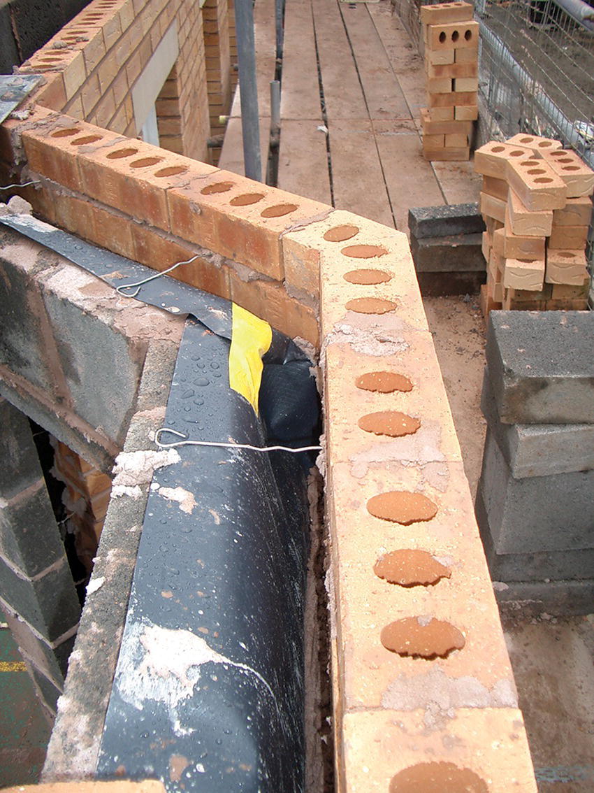
Photograph 5.5 Cavity tray to a cavity wall.
Polymer‐based sheets
Polymer‐based sheets, such as pitch polymer and copolymer thermoplastic, are thinner than bitumen sheets and are used where the thicker bitumen DPC mortar joint would be unsightly. This DPC material, which has its laps sealed with adhesive, may be punctured by sharp particles and edges. Copolymer thermoplastic DPCs have better tensile strength and higher tear and puncture resistance as compared to pitch polymer DPCs.
Ethylene propylene diene monomer (EPDM) rubber sheets
EPDM rubber sheet materials are also available.
Semi‐rigid DPCs
Mastic asphalt
Mastic asphalt, spread hot in one coat to a thickness of 13 mm, forms a semi‐rigid DPC, impervious to moisture and water. Moderate settlement in a wall may well cause a crack in the asphalt, through which moisture or water may penetrate. It is an expensive form of DPC, which shows on the face of walls as a thick joint, and is rarely used.
Rigid DPCs
Slate
Thin slates are sufficiently impermeable to water to serve as an effective DPC in solid walls of brick or stone. Slates are laid on a bed of mortar in two courses, with staggered joints, as illustrated in Figure 5.27. Because of the small units of slate, and the joints being staggered, this DPC can remain reasonably effective where moderate settlement occurs. To be effective, the edges of the slates should be exposed on a wall face and not be covered, which makes a deep joint and a strong architectural statement. This form of construction is rarely used today, but is seen in existing buildings, and knowledge of the technology is of use when renovating such buildings.
Brick DPCs
Two or three courses of dense engineering bricks may form an effective DPC. The effectiveness of the DPC is determined more by the permeability of the joining material than the bricks. This is rarely used these days other than as an architectural feature at the base of the building (and usually in conjunction with a modern flexible DPC).

Figure 5.27 Traditional slate DPC.

Figure 5.28 DPC at different levels.
DPCs in cavity walls
A requirement of the Building Regulations is that the cavity should be carried down at least 150 mm below the level of the lowest DPC (Figures 5.28, 5.29a, 5.29b, and 5.30). A DPC in an external wall that should ideally be at the same level as the DPM for the convenience of overlapping the two materials to make a damp‐proof joint. Where the DPCs in both leaves of a cavity wall are at least 150 mm above outside ground level and the floor level, or just above ground level, it is necessary to dress the DPM up the wall and into the level of the DPC. Figures 5.29a, 5.29b, and 5.30 show various methods of dressing the DPC to meet the DPM. This is a laborious operation, which makes it difficult to make a moisture‐tight joint at angles and intersections. The solution is to lay the DPC in the inner leaf of the cavity wall, level with the DPM in the floor, as illustrated in Figure 5.28.
Where the level of the foundation is near the surface, as with trench fill systems, it may be convenient to build two or more courses of solid blockwork up to ground level on which the cavity wall is raised, as illustrated in Figures 5.28 and 5.29a. As little vegetable topsoil has been removed, the floor level finishes some way above ground, and the DPM in the floor can be united with the DPC at the same level. The cavity insulation is taken down to the base of the cavity to continue wall insulation down to serve, in part, as edge insulation to the floor construction (Figure 5.29a).

Figure 5.29 (a) DPC (tray) at different heights; (b) cavity tray on top of partially filled cavity.
It is accepted practice to finish the cavity in external walling at the level of the DPC, at least 150 mm above ground. The wall is built as a solid wall up to 150 mm below the DPC, as illustrated in Figure 5.28, or the cavity below ground is filled with concrete to resist the ground pressure (Figures 5.29a, 5.29b, and 5.30). With this arrangement, the requirements of the Building Regulations recommend the use of a cavity tray at the bottom of the cavity. Various arrangements of cavity trays are shown in Figures 5.29a, 5.29b, and 5.30. This tray takes the form of a sheet of flexible, impermeable material, such as one of the flexible DPC materials, which is laid across the cavity from a level higher in the inner leaf, so that it falls towards the outer leaf to catch and drain any snow or moisture that might enter the cavity. The cavity thus acts as both tray and DPC to the cavity wall leaves.
Figure 5.30 DPC – cavity tray with rigid insulation to reduce thermal bridging.
5.6 Solid wall construction
Up to the early part of the twentieth century, loadbearing walls were usually built as solid brickwork of adequate thickness to resist the penetration of rain to the inside face, and to safely support the loads common to buildings both large and small. This has largely been replaced by cavity wall construction in the UK, although many buildings still exist that were built with solid walls.
A solid wall of brick will resist the penetration of rain to its inside face by absorbing some rainwater that subsequently, in dry periods, evaporates to outside air. The penetration of rainwater into the thickness of a solid wall depends on the exposure of the wall to driving rain and the permeability of the bricks and mortar to water. A solid wall of 1 B thickness may well be sufficiently thick to prevent the penetration of rainwater to its inside face in the sheltered positions common to urban areas on low‐lying land. In positions of moderate exposure, a solid wall 11/2 B thick will be effective in resisting the penetration of rainwater to its inside face. In exposed positions, such as high ground and near the coast, a wall of 2 B thickness may be needed to resist penetration to inside faces, although a less thick wall protected with rendering, slate or tile hanging may be a more economical solution.
Rendering
The word ‘rendering’ is used in the sense of rendering the surface of a brick or block wall smooth by the application of a wet mix of lime, cement and sand over the face of the wall. The rendering dries and hardens to a decorative protective coating that varies from dense and smooth to a coarse and open textured. Rendering improves the wall’s resistance to rain penetration and alters its appearance.
Common bricks, concrete and clay blocks do not provide what is commonly considered to be an attractive external finish for buildings. The external faces of walls built with these materials are usually rendered with two or three coats of cement and lime mixed with natural aggregate, and finished either smooth or textured. Because an external rendering generally improves the resistance of a wall to rain penetration, the walls of buildings on the coast and on high ground are often rendered externally to provide additional weather protection. External paints specially formulated for rendered surfaces may provide additional protection, while also helping to improve the appearance of the surface with the addition of some colour. In certain parts of the UK, rendering is the traditional finish to all buildings, old or new. Rendering is also used as a relatively cheap and convenient way of improving the weather resistance of old, less durable walls.
Renders depend on a strong bond to the background wall, on the mix used in the rendering material and on the surface finish of the background. The rendering should have a strong bond or key to the background wall as a mechanical bond between the rendering and the wall, so that the bond resists the drying shrinkage inevitable in any wet‐applied mix of rendering. The surface of the background wall should provide a strong mechanical key for the rendering by the use of keyed flettons, raking out the mortar joints, hacking or scoring otherwise dense concrete surfaces and hacking smooth stone surfaces. If there is not a strong bond of rendering to background walls, the rendering may shrink, crack and come away from the background, and water will enter the cracks and saturate the background, from which it will not readily evaporate. As a general rule, the richer the mix of cement in the rendering material, the stronger should be the background material and key.
The mixes for renderings depend on the background wall, with lean mixes of cement and lime being used for soft porous materials and the richer cement and lime mixes for the denser backgrounds, so that the density and porosity of the rendering corresponds roughly to that of the background. The types of external rendering used are smooth (wood‐float finish), scraped finish, textured finish, pebbledash (drydash), roughcast (wetdash) and machine‐applied finish.
Types of render
Smooth or wood‐float finish
Smooth (wood‐float finish) rendering is usually applied in two coats. The first coat is spread by trowel and struck off level to a thickness of about 11 mm. The surface of the first coat is scratched before it dries to provide key for the next coat. The first coat should be allowed to dry out. The next coat is spread by trowel and finished smooth and level to a thickness of about 8 mm. The surface of smooth renderings should be finished with a wood float rather than a steel trowel. A steel trowel brings water and the finer particles of cement and lime to the surface, which, on drying out, shrink and cause surface cracks, whereas a wood float (trowel) leaves the surface coarse‐textured and less liable to surface cracks. Three‐coat rendering is used mostly in exposed positions to provide a thick protective coating to walls. The two undercoats are spread, scratched for key and allowed to dry out to a thickness of about 10 mm for each coat; the third or finishing coat is spread and finished smooth to a thickness of 6–10 mm.
Spatterdash
Smooth, dense wall surfaces, such as dense brick and cast in‐situ concrete, afford poor key and little suction for renderings. Such surfaces can be prepared for rendering by the application of a spatterdash of wet cement and sand. A wet mix of cement and clean sand (mix 1:2, by volume) is thrown on to the surface and left to harden without being trowelled smooth. When dry, it provides a surface suitable for the rendering, which is applied in the normal way.
Scraped‐finish rendering
An undercoat and finish coat are spread as for a smooth finish, and the finished‐level surface, when it has set, is scraped with a steel straight edge or saw blade to remove some 2 mm from the surface to produce a coarse‐textured finish.
Textured finish
Textured rendering is usually applied in two coats. The first coat is spread and allowed to dry, as previously described. The second coat is then spread by trowel and finished level. When this second coat is sufficiently hard, but still wet, its surface is textured with wood combs, brushes, sacking, wire mesh or old saw blades. A variety of effects can be obtained by varying the way in which the surface is textured. An advantage of textured rendering is that the surface scraping removes any scum of water, cement and lime that may have been brought to the surface by trowelling and which might otherwise have caused surface cracking.
Pebbledash (drydash) finish
Pebbledash finish is produced by throwing dry pebbles, shingle or crushed stone on to, and lightly pressed into, the freshly applied finish coat of rendering, so that the pebbles adhere to the rendering but are mostly left exposed as a surface of pebbles. Pebbles of 6–13 gauge are used. The undercoat and finish coat are of a mix suited to the background, and are trowelled and finished level. The advantage of this finish is that the pebbledash masks any hair cracks that may open due to the drying shrinkage of the rendering.
Roughcast (wetdash) finish
A wet mix of rendering is thrown on to the matured undercoat by hand to a thickness of 6–13 mm to produce a rough, irregular‐textured finish. The gauge of the aggregate used in the wet mix determines the finish.
Machine‐applied finish
A wet mix of rendering is thrown on to a matured undercoat by machine to produce a regular, coarse‐textured finish. The surface texture is determined by the gauge of the aggregate used. This may have the natural colour of the materials or be coloured to produce what are called ‘Tyrolean finishes’.
Maintenance of render
Render is subject to staining over time as rain and moisture combine with pollutants in the air to discolour the render. This is often linked to run off from projections, such as window cills and wall vents. When exposed to solar radiation in the summer months, the staining may disappear in some instances, but not on shaded and north‐facing rendered walls. Regular cleaning will be required, as determined by the render finish and the micro‐climate of the building.
Slate and tile hanging
In positions of very severe exposure to wind‐driven rain, as on high open ground facing the prevailing wind and on the coast facing the open sea, it is necessary to protect both solid and cavity walls with an external cladding. Natural or manufactured slates and tiles can be used, hung on timber battens nailed to counter battens. Timber counter battens (50 × 25 mm) are nailed at 300‐mm centres up the face of the wall, to which timber slating or tiling battens are nailed at centres suited to the gauge (centres) necessary for double‐lap slates or tiles, as illustrated in Figure 5.31. As protection against decay, pressure‐impregnated softwood timber battens should be used, secured with non‐ferrous fixings.
Where slate or tile hanging is used as cladding to a solid wall of buildings that are normally heated, then the thermal insulation can be fixed to the wall behind the counter battens. Rigid insulation boards are fixed with a mechanically operated hammer gun that drives nails through both counter battens, a breather paper and the insulation boards, into the wall. The continuous layer of breather paper that is fixed between the counter battens and the insulation is resistant to the penetration of water in liquid form, but will allow water vapour to pass through it. Its purpose is to protect the outer surface of the insulation from cold air and any rain that might penetrate the hanging, and to allow the movement of vapour from within the structure to the external environment.
Figure 5.31 Slate hanging.
For vertically hung slating, it is usual to use one of the smaller slates, such as the 405 × 205 mm slate, which is headnailed to 50 × 25 mm battens and is less likely to be lifted and dislodged in high wind than longer slates would be. Each slate is nailed with non‐ferrous nails to overlap the two slates below it, as illustrated in Figure 5.31, and double‐lapped by overlapping the head of slates two courses below.
At angles and the sides of openings, a slate 1½ the width of slates is used to complete the overlap. This width of slate is specifically used to avoid the use of a half‐width slate that might easily be displaced in the wind. Internal and external angles are weathered by lead soakers, which are hung over the head of slates, to overlap and make the joint weathertight. Slate hanging is fixed either to overlap or butt to the side of window and door frames, with exposed edges of slates pointed with cement mortar or weathered with lead flashings. At lower edges of slate hanging, a projection is formed on or in the wall face by means of blocks, battens or brick corbel courses, on to which the lower courses of slates and tiles bell outwards slightly to throw water clear of the wall below.

Figure 5.32 Tile hanging.
Tile hanging is nailed to 40 × 20 mm tiling battens fixed at centres to counter battens to suit the gauge of plain tiles. Each tile is hung to battens and also nailed, as security against wind, as illustrated in Figure 5.32. At internal and external angles, special angle tiles may be used to continue the bond around the corner, as illustrated in Figure 5.32. As an alternative, and also at the sides of openings, 1½‐width tiles may be used with lead soakers to angles and pointing to exposed edges.
Thermal insulation to solid walls
To provide adequate insulation to a solid wall, it is necessary to fix a layer of lightweight insulating material to either the internal or exterior face of the wall.
Internal insulation
Internal insulation is used where solid walls have sufficient resistance to the penetration of rain, and/or alteration to the external appearance is not permitted or desirable. A disadvantage of internal insulation is that, as the insulation is at, or close to, the internal surface, it will prevent the wall behind from acting as a heat store where constant low‐temperature heating is used. There is also potential for interstitial condensation to form on the face of the wall; therefore, a vapour barrier should be used on the surface of the insulation to ensure that moisture is restricted from meeting the cold face of the wall. Photograph 5.6 shows 150 mm of polyisocyanurate (PIR) insulation fixed to the internal side of a solid 250‐mm‐thick clay brick wall. The insulation on the plane elements provides an approximate U‐value of 0.15 W/m2K.
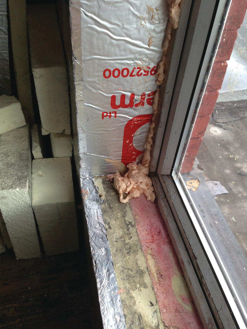
Photograph 5.6 150 mm of polyisocyanurate.
It is usual to cover the insulating layer with a lining of plasterboard or plaster, so that the combined thickness of the inner lining and the wall have the required U‐value. Internal linings for thermal insulation are either preformed laminated panels that combine a wall lining of plasterboard glued to an insulation board, or separate insulation material fixed to the wall and then covered with plasterboard or plaster. The method of fixing the lining to the inside wall surface depends on the surface to which it is applied.
Adhesive fixing
Adhesive fixing directly to the inside wall face is used for preformed laminate panels and rigid insulation boards. Where the inside face of the wall is clean, dry, level and reasonably smooth, the panels or boards are secured with an organic‐based gap‐filling adhesive, applied in dabs and strips to the back of the boards or panels, or to both the boards and the wall. The panels or boards are then applied and pressed into position against the wall face, and their position adjusted with a foot lifter.
When the surface of the wall is uneven, the panels or boards are fixed with dabs or bonding, applied to both the wall surface and the back of the lining. Dabs are small areas of wet plaster bonding applied at intervals on the surface with a trowel, as a bedding and adhesive. The lining is applied and pressed into position against the wall. The wet dabs of bonding allow for irregularities in the wall surface, and also serve as an adhesive. Some lining systems use secondary fixing in addition to the adhesive – for example, non‐ferrous or plastic nails, or screws, driven or screwed through the insulation boards into the wall. In order to prevent air leakage around the edges of plasterboards applied using dot and dab, a ribbon (continuous strip) of plaster or fixing adhesive should be positioned around the perimeter of the plasterboard. Figure 5.33 is an illustration of laminated insulation panels fixed to the inside face of a solid wall.
Mechanical fixing
As an alternative to adhesive fixing, the insulating lining and the wall finish can be fixed to wood battens (that are nailed to the wall) with packing pieces, as necessary, to form a level surface. The battens should be impregnated against rot and fixed with non‐ferrous fixings. The insulating lining is fixed either between or across the battens, and an internal lining of plasterboard is then nailed to the battens, through the insulation. The thermal resistance of wood is less than that of most insulating materials. When the insulating material is fixed between the battens, there will be thermal bridges through the battens, which may cause staining on wall faces.
Internal wall finish
An inner lining of plasterboard can be finished by taping and filling the joints, or with a thin‐skim coat of plaster. A finish of lightweight plaster and finishing coat is applied to the ready‐keyed surface of some insulating boards, or to expanded metal lathing fixed to battens. Laminated panels of insulation, lined on one side with a plasterboard finish, are made specifically for the insulation of internal walls. The panels are fixed with adhesive or mechanical fixings to the inside face of the wall.

Figure 5.33 Internal insulation.
Vapour barriers and checks
Moisture vapour pressure from warm moist air inside insulated buildings may find its way through internal linings and condense on cold outer faces. Where the condensate is absorbed by the insulation, it will reduce the efficiency of the insulation, and where condensation saturates battens, they may rot. With insulation that is permeable to moisture vapour, a vapour check should be fixed on the room side of the insulation. A vapour barrier is one that completely stops the movement of vapour through it, and a vapour check is one that substantially stops vapour. As it is difficult to make a complete seal across the whole surface of a wall, including all overlaps of the barrier and at angles, it is in effect impossible to form a barrier, and the term ‘vapour check’ should more properly be used. Sheets of polythene with edges overlapped and taped together are commonly used as a vapour check.
External wall insulation
Insulating materials by themselves do not provide a satisfactory external finish to walls against rain penetration, nor do they provide an attractive finish; thus, they are covered with a finish of cement rendering, paint or a cladding material such as tile, slate, profiled sheeting or weatherboarding. For rendered finishes, one of the inorganic insulants, rockwool or cellular glass in the form of rigid boards, is most suited. For cladding, one of the organic insulants is used, because it is thinner for a comparable U‐value.
Because the rendering is applied over a layer of insulation, it will be subject to greater temperature fluctuations than if it were applied directly to a wall, and so it is more liable to crack. To minimise cracking due to temperature change and moisture movements, the rendering should be reinforced with a mesh securely fixed to the wall, and movement joints should be formed at intervals of not more than 6 m. The use of a light‐coloured finish and rendering incorporating a polymer emulsion can also help to reduce cracking. As the overall thickness of the external insulation and rendering is too great to be returned into the reveals of existing openings, it is usual to return the rendering by itself, or to fix some non‐ferrous or plastic trim to mask the edge of the insulation and rendering. This will result in the reveals of openings acting as thermal bridges, which is not desirable. Figure 5.34 is an illustration of insulated rendering applied externally.

Figure 5.34 External insulation on expanded metal lath (EML).
Slabs of compressed mineral wool are secured to the external face of the wall with stainless steel brackets, fixed to the wall to support and restrain the blocks that are arranged with either horizontal, bonded joints or vertical and horizontal continuous joints.
The insulation can be fixed by purpose‐made plugs and mechanical fixings. These fixings reduce the thermal bridges that can occur when frames are used to attach the insulation.
Openings in solid walls
For the strength and stability of walling, the size of openings in loadbearing walls is limited by regulations.
Jambs of openings
The jambs of openings for windows and doors in solid walls may be plain (square) or rebated. Plain or square jambs are used for small‐section window or door frames of steel, and also for larger‐section frames where the whole of the external face of frames is to be exposed externally. The bonding of brickwork at square jambs is the same as for stop ends and angles with a closer next to a header in alternate courses to complete the bond. Rebated jambs are used to provide some protection to window/door frames (Figure 5.35).
Rebated jambs
Historically, rebated jambs have been used as a feature to protect window and door frames. Figure 5.35 is a diagram of one rebated jamb, illustrating some commonly used terms. The thickness of brickwork that shows at the jamb of openings is described as the ‘reveal’. With rebated jambs, there is an ‘inner reveal’ and an ‘outer reveal’, separated by the rebate. Figure 5.36 shows the brick arrangements for forming a rebated jamb in a Flemish bond. The amount of labour involved in creating such features makes them expensive, and they are hence very rarely used nowadays.

Figure 5.35 Rebated jamb.

Figure 5.36 Bonding at rebated jambs.
Head of openings in solid walls
Solid brickwork over the head of openings has to be supported by either a lintel or an arch. The brickwork that the lintel or arch has to support is an isosceles triangle with 60° angles, formed by the bonding of bricks, as illustrated in Figure 5.37. The vertical joints between bricks, which overlap ¼ B, form the triangle. In a bonded wall, if the solid brickwork inside the triangle were taken out, the load of the wall above the triangle would be transferred to the bricks of each side of the opening, in what is termed ‘the arching effect’.
Figure 5.37 Head of openings.
Lintel (alternatively spelt ‘lintol’) is the name given to any single solid length of timber, stone, steel or concrete built in over an opening to support the wall above it, as shown in Figure 5.37. The ends of the lintel must be built into the brick or blockwork over the jambs to convey the weight carried by the lintel to the jambs. The area of wall on which the end of a lintel bears is termed its ‘bearing at ends’. The wider the opening, the more weight the lintel has to support, and the greater its bearing at ends must be to transmit the load it carries to an area capable of supporting it. For convenience, its depth is usually made a multiple of brick course height (75 mm), and the lintels are not usually less than 150 mm deep. Hardwood timber lintels have largely been replaced by concrete and steel lintels.

Figure 5.38 Ends of reinforcing rods.
Reinforced concrete lintels
Lengths of steel rod (reinforcement) are cast into the bottom of concrete lintels to give them strength in resisting tensile or stretching forces. A minimum cover of concrete of 15 mm is necessary to avoid the possibility of corrosion and damage to the concrete around them. Reinforcing rods are usually of round‐section mild steel of 10 or 12 mm diameter for lintels up to 1.8 m span. The ends of the rods should be bent up at 90° or hooked, as illustrated in Figure 5.38. The purpose of bending up the ends is to ensure that, when the lintel does bend, the rods do not lose their adhesion to the concrete around them. After being bent or hooked at the ends, the rods should be some 50 or 75 mm shorter than the lintel at each end.
Casting lintels
The word ‘precast’ indicates that a concrete lintel has been cast inside a mould, and has been allowed time to set and harden before it is built into the wall. The words ‘in‐situ cast’ indicate that a lintel is cast in position inside a timber mould fixed over the opening in walls. Precast lintels may be used for standard door and window openings, the advantage being that, immediately after the lintel is placed in position over the opening, brickwork can be raised on it, whereas the concrete in an in‐situ cast lintel requires a timber mould or formwork and must be allowed to harden before brickwork can be raised on it. Lintels are cast in situ if a precast lintel would have been too heavy or cumbersome to have been hoisted and bedded in position. Precast lintels must be clearly marked to make certain that they are bedded with the steel reinforcement in its correct place, at the bottom of the lintel. Usually, the letter ‘T’ or the word ‘top’ is cut into the top of the concrete lintel while it is still wet.
Prestressed concrete lintels
A prestressed lintel is made by casting concrete around high‐tensile, stretched wires, which are anchored to the concrete, so that the concrete is compressed by the stress in the wires (see also Barry’s Advanced Construction of Buildings). The load applied by the stressed wires, which compress the concrete, has to be overcome before the lintel will bend. Two types of prestressed concrete lintels are available: composite lintels and non‐composite lintels.
Figure 5.39 Prestressed lintels.
Composite lintels are stressed by wires at the centre of their depth, and are used with brickwork, which acts as a composite part of the lintel in supporting loads. These comparatively thin precast lintels are built in over openings, and brickwork is then built over them. Prestressed lintels over openings more than 1200 mm wide should be supported to avoid deflection until the mortar in the brickwork has set. When used to support blockwork, the composite strength of these lintels is considerably less than when used with brickwork.
Non‐composite prestressed lintels are made for use where there is insufficient brickwork over to act compositely with the lintel, and also where there are heavy loads. These lintels are made to suit brick and block wall thicknesses, as illustrated in Figure 5.39.
Prestressed lintels may be used over openings in both internal and external solid walls. In external walls, prestressed lintels are used where the wall is to be covered with rendering externally, and for the inner leaf of cavity walls where the lintel will be covered with plaster. Precast reinforced concrete lintels may be exposed on the external face of both solid and cavity walling where the appearance of a concrete surface is desired.
Concrete boot lintels
The lintel is boot shaped in section, with the toe part showing externally. The toe is usually made 65 mm deep. The main body of the lintel is hidden inside the wall, and it is this part of the lintel that does most of the work of supporting the brickwork (Figure 5.40). The detail is sometimes built such that the toe of the lintel finishes 25 or 40 mm back from the external face of the wall, as shown in Figure 5.40, to improve the visual appearance. The brickwork built on the toe of the lintel is usually ½ B thick for openings up to 1.8 m wide. The 65‐mm deep toe, if reinforced as shown, is capable of safely carrying the two or three courses of 1/2 B–thick brickwork over it. Because the bricks are bonded, the brickwork above the top of the main part of the lintel bears mainly on it. If the opening is wider than 1.8 m, the main part of the lintel is sometimes made sufficiently thick to support most of the thickness of the wall over, as shown in Figure 5.40. The bearing at ends, where the boot lintel is bedded on the brick jambs, should be of the same area as for ordinary lintels.
Figure 5.40 Boot lintels.

Figure 5.41 Evolution of the concrete lintel from solid wall to use in cavity construction.
Although this section does not deal with cavity wall construction, Figure 5.41 illustrates how the concrete lintel used in solid wall construction evolved for use in cavity walls. Boot lintels (Figure 5.41c) should not be used in cavity wall construction, because the solid concrete provides a thermal bridge across the cavity wall. Concrete lintels can be used in a cavity wall where two separate lintels are used to support each skin (Figure 5.41). The gap between the two skins of brickwork and blockwork can be filled with an insulated cavity closer. Further information on cavity wall construction can be found later in this section.
Pressed steel lintels
Galvanised, pressed steel lintels are an alternative to concrete as a means of support to both loadbearing and non‐loadbearing internal walls. Mild steel strip is pressed to shape, welded as necessary and galvanised. The steel lintels for support over door openings in loadbearing internal walls are usually in hollow box form, as illustrated in Figure 5.42. A range of lengths and sections is made to suit standard openings, wall thicknesses, course height for brickwork and adequate bearing at ends. For use over openings in loadbearing concrete block internal walls, it is usually necessary to cut blocks around the bearing ends of these shallow‐depth lintels. The exposed lintel faces are perforated to provide a key for plaster.

Figure 5.42 Steel lintels in internal walls.
To support thin, non‐loadbearing concrete blocks over narrow door openings in partition walls, a small range of corrugated, pressed steel lintels is made to suit block thickness. These shallow‐depth galvanised lintels are made to match the depth of horizontal mortar joints to avoid the cutting of blocks. The corrugations provide adequate key for plaster run over the face of partitions and across the soffit of openings, as illustrated in Figure 5.43. These lintels act compositely with the blocks they support. To prevent sagging, they should be given temporary support at mid‐span until the blocks above have been laid and the mortar hardened.

Figure 5.43 Corrugated steel lintel in internal wall.

Figure 5.44 Brick lintels.
Brick lintels
A brick lintel may be formed as bricks on end, bricks on edge or coursed bricks laid horizontally over openings. Bricks laid in mortar give poor support to the wall above, and usually need some form of additional support. A brick‐on‐end lintel is generally known as a ‘soldier arch’ or ‘brick‐on‐end’ arch (although the bricks are laid flat). The lintel is built with bricks laid on end with stretcher faces showing, as illustrated in Figure 5.44. For openings up to about 900 mm wide, it was common to provide some support for soldier arches by building the lintel on the head of timber window and door frames. The wood frame served as temporary support as the bricks were laid, and provided support against sagging once the wall was built. A variation was to form skew‐back bricks at each end of the lintel with cut bricks, so that the slanting surface bears on a skew brick in the jambs, as illustrated in Figure 5.44. The skew back does give some little extra stability against sagging.
Brick arches
An arch, which is an elegant and structurally efficient method of supporting brickwork, has been, for centuries, the preferred means of support for brickwork over the small openings for doors and windows and for arcades, viaducts and bridges.
Semi‐circular arch
The most efficient method of supporting brickwork over an opening is by the use of a semi‐circular arch, which transfers the load of the wall it supports most directly to the sides of the opening through the arch (see Figure 5.45). A segmented arch, which takes the form of a segment (part) of a circle, is less efficient, in that it transmits loads to the jambs by both vertical and outward thrust.

Figure 5.45 Semi‐circular brick arch.
Figure 5.46 Rough and axed arches.
Rough and axed arches
The two ways of constructing a curved brick arch are with bricks laid with wedge‐shaped mortar joints or with wedge‐shaped bricks with mortar joints of uniform thickness, as illustrated in Figure 5.46. An arch formed with uncut bricks and wedge‐shaped mortar joints is termed a ‘rough brick arch’, because the mortar joints are irregular and the finished effect is rough. In time, the joints tend to crack and emphasise the rough appearance; thus, rough arch‐work is rarely used for fairface work.
Arches in fairface brickwork are usually built with bricks cut to a wedge shape, and mortar joints of uniform width. Bricks are cut (either on‐ or off‐site) to the required wedge shape by gradually chopping them to shape – hence the name ‘axed bricks’. A template, or pattern, is cut from a sheet of zinc to the exact wedge shape to which the bricks are to be cut. The template is laid on the stretcher or header face of the brick, as illustrated in Figure 5.47. Shallow cuts are made in the face of the brick on each side of the template. These cuts are made with a hacksaw blade or file, and are intended to guide the bricklayer in cutting the brick. Then, holding the brick in one hand, the bricklayer gradually chops the brick to the required wedge shape. When the brick has been cut to a wedge shape, the rough, cut surfaces are roughly levelled with a coarse rasp. From the description, this appears to be a laborious operation, but a skilled bricklayer can in fact axe a brick to a wedge shape in a few minutes. The axed wedged‐shaped bricks are built to form the arch, with uniform 10‐mm mortar joints between the bricks.
Figure 5.47 Axed brick.
Gauged brick arch
Gauged bricks are those that have been accurately prepared to a wedge shape so that they can be put together to form an arch with very thin joints between them. This does not improve the strength of the brick arch, and is done for appearance. Hard‐burnt clay facing bricks cannot be cut to the accurate wedge shape required for this work, because the bricks are too coarse‐grained. One type of brick used for gauged brickwork is called a ‘rubber brick’ (or ‘brick rubbers’), because its composition is such that it can be rubbed down to an accurate shape on a flat stone. Rubbers are made from fine‐grained sandy clays. They are moulded and then hardened by baking at a lower temperature than that at which clay bricks are burnt, the aim being to avoid fusion of the material of the bricks, so that they can easily be cut and accurately rubbed to shape.
Sheet zinc templates are cut to the exact size of the wedge‐shaped brick voussoirs. These templates are placed on the stretcher or header face of the brick to be cut, and the brick is sawn to a wedge shape with a brick saw. Then they are carefully rubbed down by hand on a large flat stone until they are the exact wedge shape required as indicated by the template. The gauged rubber bricks are built to form the arch, with joints between the bricks as thin as 1.5 mm. Mortar used between the gauged bricks is composed of either fine sand, cement and lime, or lime and water, depending on the thickness of joint. The finished effect of accurately gauged red bricks with thin white joints between them is considered very attractive. Gauged bricks are used for flat camber arches.
Two‐ring arch
Rough and axed bricks are used for both semi‐circular and segmental arches, and gauged brick for segmental and flat camber arches, to avoid the more considerable cutting necessary with semi‐circular arches. Rough, axed or gauged bricks can be laid so that either their stretcher or their header face is exposed. Semi‐circular arches are often formed with bricks showing header faces to avoid the excessively wedge‐shaped bricks or joints that occur with stretcher faces showing. This is illustrated in Figure 5.48 by the comparison of two arches of similar spans, first with stretcher face showing and then with header face showing. If the span of the arch is of any considerable width, say, 1.8 m or more, the practice is often to build it with what is termed ‘two or more rings of bricks’, as illustrated in Figure 5.48. An advantage of two or more rings of bricks showing header faces is that the bricks bond into the thickness of the wall. Where the wall over the arch is more than 1 B thick, it is practical to effect more bonding of arch bricks in walls or viaducts by employing alternate snap headers (half‐bricks) in the face of the arch.

Figure 5.48 Two‐ring arch.
Segmental arch
The curve of this arch is a segment, that is, part of a circle, and designers of a building can choose any segment of a circle that they think suits their design. By trial and error over many years, bricklayers have worked out methods of calculating the segment of a circle related to the span of this arch, which gives a pleasant‐looking shape, and which, at the same time, is capable of supporting the weight of the brickwork over the arch. The recommended segment is such that the rise of the arch is 130 mm for every metre of span of the arch.
Centring
Temporary support for brick arches is necessary, and this is usually in the form of a timber framework to the profile of the underside of the arch, called ‘centring’. It is fixed and supported in the opening while the bricks of the arch are being placed and the coursed brickwork over the arch laid. When the arch and brickwork are finished, the centring is removed. A degree of both skill and labour is involved in arch building – in setting out the arch, cutting bricks for the arch and the abutment of coursed brickwork to the curved profile of the arch. Thus, an arched opening is more expensive than a plain lintel head.
Figure 5.49 Flat‐gauged camber arch.
Flat camber arch
A flat camber arch is not a true arch, as it is not curved, and might well be more correctly called a flat brick lintel with voussoirs radiating from the centre, as illustrated in Figure 5.49. The bricks from which the arch is built may be either axed or gauged to the shape required, so that the joints between the bricks radiated from a common centre and the widths of voussoirs measured horizontally along the top of the arch are the same. This width will be 65 mm or slightly less, so that there are an odd number of voussoirs; the centre is the key brick.
The centre from which the joints between the bricks radiate is usually determined either by making the skew or slating surface at the end of the arch 60° to the horizontal, or by calculating the top of this skew line as lying 130 mm from the jamb for every metre of span. If the underside or soffit of this arch were made absolutely level, it would appear to be sagging slightly at its centre. This is an optical illusion, and it is corrected by forming a slight rise or camber on the soffit of the arch. This rise is usually calculated at 6 or 10 mm for every metre of span, and the camber takes the form of a shallow curve. The camber is allowed for when cutting the bricks to shape. In walls built of hard, coarse‐grained facing bricks, this arch is usually built of axed bricks. In walls built of softer, fine‐grained facing bricks, the arch is usually built of gauged rubbers, and is termed a ‘flat‐gauged camber arch’. This flat arch must be of such height on face that it bonds in with the brick course of the main walling. The voussoirs of this arch, particularly those at the extreme ends, are often longer overall than a normal brick, and the voussoirs have to be formed with two bricks cut to shape.
Flat‐gauged camber arch
The bricks in this arch are jointed with lime and water, and the joints are usually 1.5 mm thick. Lime is soluble in water and does not adhere strongly to bricks, and in time the jointing material between the bricks may perish and the bricks might slip out of position. To prevent this, joggles are formed between the bricks. These joggles take the form of semi‐circular grooves cut in both bed faces of each brick, as shown in Figure 5.49, into which mortar is run.
Types of stone walling
Rubble walling
Rubble walling is extensively used for agricultural buildings in towns and villages in those parts of the country where a local source of stone is readily available. The various forms of rubble walling may be classified as ‘random rubble’ and ‘squared rubble’.
Random rubble
Uncoursed random rubble stones of all shapes and sizes are laid in mortar, as illustrated in Figure 5.50a. No attempt is made to select and lay stones in horizontal courses. There is some degree of selection to avoid excessively wide mortar joints, and also to bond stones by laying some longer stones, both along the face and into the thickness of the wall, so that there is a bond stone in each square metre of walling. At quoins, angles and around openings, selected stones or shaped stones are laid to form roughly square angles.
Random rubble brought to course is similar to random rubble uncoursed, except that the stones are selected and laid such that the walling is roughly levelled in horizontal courses at vertical intervals of 600–900 mm, as illustrated in Figure 5.50b. Transverse and longitudinal bond stones are used.
Squared rubble
Squared rubble uncoursed is laid with stones that come roughly square from the quarry in a variety of sizes. The stones are selected at random, are roughly squared with a walling hammer and laid without courses, as illustrated in Figure 5.51a. As with random rubble, both transverse and longitudinal bond stones are laid at intervals. ‘Snecked rubble’ is a term for squared rubble in which a number of small squared stones, ‘snecks’, are laid to break up long continuous vertical joints. Snecked rubble is often difficult to distinguish from squared random rubble.
Figure 5.50 Random rubble uncoursed (a) and coursed (b).
Figure 5.51 (a) Squared rubble uncoursed; (b) squared rubble coursed.

Figure 5.52 (a) Squared rubble coursed; (b) polygonal walling.
Squared rubble brought to course is constructed from roughly square stone rubble, selected and squared so that the work is brought to courses every 300–900 mm intervals, as illustrated in Figure 5.51b. Squared rubble course is built with stones that are roughly squared, so that the stones in each course are roughly the same height and the courses vary in height, as illustrated in Figure 5.52a. The face of the stones may be roughly dressed to give a rock‐faced appearance, or dressed smooth to give a more formal appearance.
Polygonal walling
Stones that are taken from a quarry where the stone is hard have no pronounced laminations and come in irregular shapes that can be laid as polygonal walling. The stones are selected and roughly dressed to fit when laid, to an irregular pattern, with no attempt at regular courses or vertical joints. At corners and as a base, roughly square‐edged stones are used, as illustrated in Figure 5.52b.
Flint walling
Flint walling is traditional to East Anglia and the south and southeast of England. Both field and shore flints are used. The flints used for walling are up to 300 m in length and 75–250 mm in width and thickness. The flints or cobbles may be used whole or split to show the heart of the flint, and also knapped or snapped so that they show a roughly square face. Flint walling is built with a dressing of stone or brick at angles and in horizontal lacing courses that level the wall at intervals. Figure 5.53a is an illustration of whole flints laid without courses in brick dressing to angles and as lacing, and Figure 5.53b is an illustration of knapped flints laid to courses in stone dressing.
Figure 5.53 (a) Whole‐flint wall; (b) knapped flint wall.
Ashlar masonry joints
Ashlar stones may be finished with smooth faces and bedded with thin joints, or the stones may have their exposed edges cut to form a channelled or V joint to emphasise the shape of each stone and to give the wall a heavier, more permanent appearance. The ashlar stones of the lower floor of large buildings are often finished with channelled or V joints and the wall above with plain ashlar masonry to give the base of the wall an appearance of strength. Ashlar masonry finished with channelled or V joints is said to be ‘rusticated’. A channelled joint (rebated joint) is formed by cutting a rebate on the top and one side edge of each stone, so that, when the stones are laid, a channel rebate appears around each stone, as illustrated in Figure 5.54a. The rebate is cut on the top edge of each stone, so that, when the stones are laid, rainwater, which may run into the horizontal joint, will not penetrate the mortar joint. A V joint (chamfered joint) is formed by cutting all four edges of stones with a chamfer, so that, when they are laid, a V groove appears on the face, as illustrated in Figure 5.54b. Often, the edges of stones are cut with both V and channelled joints to give greater emphasis to each stone.

Figure 5.54 (a) Channelled joint; (b) V joint.
Tooled finish
Plain ashlar stones are usually finished with flat faces. The stones may also be finished with their exposed faces tooled to show the texture of the stone. Some of the tooled finishes used with masonry are illustrated in Figure 5.55. It is the harder stones such as granite and hard sandstone that are more commonly finished with rock face, pitched face, reticulated face or vermiculated face. The softer, fine‐grained stones are usually finished as plain ashlar.
Cornice and parapet walls
It is common practice to raise masonry walls above the levels of the eaves of a roof, as a parapet. The purpose of the parapet is partly to obscure the roof and also to provide a depth of wall over the top of the upper windows for the sake of improving the appearance in the proportion of the building as a whole. In order to provide a decorative termination to the wall, a course of projecting moulded stones is formed. This projecting stone course is termed a ‘cornice’, and it is generally formed of one or more courses of stone below the top of the parapet (Figure 5.56). This projection provides some protection to the wall below.
Figure 5.55 Tooled finishes.

Figure 5.56 Cornice and parapet.
The parapet wall usually consists of two or three courses of stones capped with coping stones bedded on a DPC of sheet metal. The parapet is usually at least 1 B thick, or of such thickness that its height above the roof is limited by the requirements of the Building Regulations. The parapet may be built of solid stone or stones bonded to a brick backing. The cornice is constructed of stones of about the same depth as the stones in the wall below, cut such that they project, and are moulded for appearance sake. Because the stones project, their top surface is weathered (slopes out) to throw water off.
Saddle joint
The projecting, weathered top surface of coping stones is exposed, and the rain water running off it will, in time, saturate the mortar in the vertical joints between the stones. To prevent rain soaking into these joints, it is usual to cut the stones to form a saddle joint, as illustrated in Figure 5.56. The exposed top surface of the stones has to be cut to slope out (weathering), and a projecting quarter circle of stone is left on the ends of each stone when this cutting is executed. When the stones are laid, the projections on the ends of adjacent stones form a protruding semi‐circular saddle joint, which causes rain to run off away from the joints.
Weathering to cornices
Because cornices are exposed and liable to saturation by rain and possible damage by frost, it is good practice to cover the exposed top surface of cornice stones cut from limestone or sandstone with sheet metal. The sheet metal covering is particularly useful in urban areas, where airborne pollutants may gradually erode stone. Sheet lead is preferred as a non‐ferrous covering because of its ductility, which facilitates shaping, and its impermeability. Sheets of lead, Code No. 5, are cut and shaped for the profile of the top of the cornice, and are laid with welted (folded) joints at 2‐m intervals along the length of the cornice. The purpose of these comparatively closely spaced joints is to accommodate the inevitable thermal expansion and contraction of the lead sheet. The top edge of the lead is dressed up some 75 mm against the parapet as an upstand, and turned into a raglet (groove) cut in the parapet stones and wedged in place with lead wedges. The joint is then pointed with mortar. The bottom edge of the lead sheets is dressed (shaped) around the outer face of the stones and welted (folded). To prevent the lower edge of the lead sheet from lifting up in high winds, 40‐mm‐wide strips of lead are screwed to lead plugs that are set in holes in the stone at 750‐mm intervals, and are folded into the welted edge of the lead, as illustrated in Figure 5.57. Where cornice stones are to be protected with sheet lead weathering, there is no purpose in cutting saddle joints.

Figure 5.57 Lead weathering to cornice.
Cement joggle
Cornice stones project, and one or more stones might in time settle slightly, such that the decorative line of the mouldings cut on them would be broken, ruining the appearance of the cornice. To prevent this possibility, shallow V‐shaped grooves are cut in the ends of each stone, so that, when the stones are put together, these matching V grooves form a square hole, into which cement grout is run. When the cement hardens, it forms a joggle, which locks the stones in their correct position.
Dowels
To maintain parapet stones in their correct positions in a wall, slate dowels are used. The stones in a parapet are not kept in position by the weight of walling above, and these stones are, therefore, usually fixed with slate dowels. These dowels consist of square pins of slate that are fitted to holes cut in adjacent stones, as illustrated in Figure 5.56.
Cramps
Coping stones are bedded on top of a parapet wall as a protection against water soaking down into the wall below. There is a possibility that the coping (capping) stones may suffer some slight movement, and cracks may develop in the joints between them. Rain may then saturate the parapet wall below, and frost action may contribute to some movement and eventual damage. To keep coping stones in place, a system of cramps is used. Either slate or non‐ferrous metal is used to cramp the stones together. A short length of slate, shaped with dovetail ends, is set in cement grout (cement and water) in dovetail grooves in the ends of adjacent stones, as illustrated in Figure 5.58a. As an alternative, a gunmetal cramp is set in a groove and mortise in the end of each stone and bedded in cement mortar, as illustrated in Figure 5.58b. For coping stones cut from limestone or sandstone, a sheet metal weathering is sometimes dressed over coping stones. The weathering of lead is welted and tacked in position over the stones.

Figure 5.58 (a) Slate cramp; (b) metal cramp.
Openings to stone walls
Masonry over door and window openings may be supported by flat‐stone lintels or by segmental or semi‐circular arches.
Figure 5.59 Segmental stone arch.
Lintels
A stone lintel for small openings of up to about a metre width can be formed of one whole stone, with its ends built into jambs and its depth corresponding to one or more stone courses. The poor tensile strength of stone limits the span of single‐stone lintels, unless they are to be disproportionately deep. Over openings wider than about a metre, it is usual to form lintels with three or five stones cut in the form of a flat arch. The stones are cut such that the joints between the ends of stones radiate from a common centre, so that the centre, or key stone, is wedge shaped, as illustrated in Figure 5.59. The stones are cut so that the lower face of each stone occupies a third or a fifth of the width of the opening.
To prevent the key stone from sinking due to settlement and so breaking the line of the soffit, it is usual to cut half‐depth joggles in the ends of the key stone to fit to rebates cut in the other stones. The joggles and rebates may be cut to the full thickness of each stone and show on the face of the lintel, or more usually the joggles and rebates are cut on the inner half of the thickness of stones as secret joggles, which do not show on the face, as illustrated in Figure 5.60. The depth of the lintel corresponds to a course height, with the ends of the lintel built in at jambs as end bearing. Stone lintels are used over both ashlar and rubble walling. The use of lintels is limited to comparatively small openings due to the tendency of the stones to sink out of horizontal alignment. For wider openings, some form of arch is used.
Arches
A stone arch consists of stones specially cut, such that the joints between stones radiate from a common centre; the soffit is arched, and the stones bond in with the surrounding walling. The individual stones of the arch are termed ‘voussoirs’, the arched soffit the ‘intrados’ and the upper profile of the arch stones the ‘extrados’ (see Figure 5.59) The voussoirs of the segmental arch are cut with steps that correspond in height with stone courses, to which the stepped extrados is bonded. The stones of an arch are cut so that there are an uneven number of voussoirs with a centre or key stone. The key stone is the last stone to be put in place as a key to the completion and the stability of the arch – hence the term ‘key stone’.

Figure 5.60 Stone lintel with secret joggle joints.
Figure 5.61 Semi‐circular stone arch with crossetted voussoirs.
Crossetted arch
The semi‐circular arch, illustrated in Figure 5.61, is formed with stones that are cut to bond into the surrounding walling to form stepped extrados, and also to bond horizontally into the surrounding stones. The stones, voussoirs, are said to be ‘crossetted’, or crossed. The stones radiate from a common centre, with an odd number of stones arranged around the half‐circle, so that there is a central key stone. The extent to which the crossetted top of each stone extends into the surrounding masonry is not necessarily dictated by the stretcher bond of the main walling. Any degree of bond into the main wall may be chosen and the bond of masonry adjusted accordingly. The effect of the crossetted voussoir is to emphasise the arch as structurally separate from the coursed masonry, and it is chosen for that effect. There is some waste involved in cutting stones to achieve this effect.
5.7 Cavity wall construction
The idea of forming a vertical cavity in brick walls was first proposed early in the nineteenth century and developed through the twentieth century. The outer leaf and the cavity serve to resist the penetration of rain to the inside face and the inner leaf to support floors, provide a solid internal wall surface and, to some extent, act as insulation against the transfer of heat. Various widths of cavity were proposed from the first 6‐inch (150‐mm) cavity, including a later 2‐inch (50‐mm) cavity, which was followed by proposals for 3‐, 4‐ and 5‐inch‐wide cavities. Early cavity walls were constructed with bonding bricks laid across the cavity at intervals to tie the two leaves together. Either whole bricks with end closers or bricks specially made to size and shape for the purpose were used. Later, iron ties were used to tie the two leaves together. From the middle of the twentieth century, it became common practice to construct the external walls of houses as a cavity wall with a 50‐mm‐wide cavity and metal wall ties. The need to improve the thermal resistance of cavity walls resulted in the cavity being filled, either partially or fully, with insulating materials, as the cavity provided a convenient space for adding the thermal insulating material (see Figure 5.62). With a fully filled cavity, the ‘cavity wall’ has evolved into a sandwich construction, although we still use the term ‘cavity wall’. More stringent regulations have led to an increase in the cavity width to accommodate a greater depth of thermal insulating material, although, with the development of ultra‐thin insulating materials, it is likely that the width of the cavity may be reduced in some circumstances. The depth of some cavity walls has built up to over 500 mm thickness of different materials combining to make a highly insulated, fully filled cavity wall. This composite construction is still referred to as a ‘cavity wall’, although there is no longer an air gap (cavity) in the construction. Using 300 mm of mineral wool, lightweight blocks with plaster are used to seal and create an airtight fabric. Highly insulated, fully filled cavity walls can be constructed to U‐values of 0.1 W/m2K, meeting nearly zero fabric standards, as shown in Figure 5.62. External walls may also be constructed of stone, or combinations of stone and brickwork, to achieve the desired aesthetic.
Figure 5.62 Thermally resistant cavity wall construction.
(Source: courtesy of Felix Thomas).
Strength and stability
Cavity wall construction relies on the combination of an external and internal skin that is tied together with wall ties. The external skin, which is not loadbearing, is held stable by the internal skin, which is loadbearing. When tied together, the two skins offer increased rigidity and stability (which relies on the two skins remaining connected). The practical guidance in Approved Document A accepts a cavity of 50–100 mm for cavity walls having leaves at least 90 mm thick, built of coursed brickwork or blockwork, with wall ties spaced at 450 mm vertically and 900–750 mm horizontally for cavities of 50–100 mm wide, respectively. As the limiting conditions for the thickness of walls related to height and length are the same for a solid bonded wall 190 mm thick as they are for a cavity wall of two 90‐mm‐thick leaves, it is accepted that the wall ties give the same strength and stability to two separate leaves of brickwork as the bond in solid walls.
Wall ties
Early metal ties were prone to corrosion (Figure 5.63), and many (non‐galvanised) steel ties used during 1930s–1950s have had to be replaced. Where ties break or corrode, the external skin of stone or brick will bow and deform as it expands and contracts with thermal and moisture movement. Galvanised steel, stainless steel and plastic cavity ties were introduced to resolve the problem. The ties had clips and deformations at their centre, known as a ‘drip’, designed to encourage any moisture that passed on to the tie to drip off at the deformation. The moisture collected on the drip drops down into the cavity and out through the external leaf of the cavity.

Figure 5.63 Cavity wall construction, development of cavity ties and insulants.
(Source: courtesy of Felix Thomas).
Wall ties must be protected during delivery, storage, handling and use against the inevitable knocks that may perforate the toughest coating to mild steel, and the consequent probability of rust occurring. Wall ties made from stainless steel will not suffer corrosion during the useful life of buildings. Sharp edges of steel wall ties can pose a hazard to bricklayers. It is common practice to build up one leaf of the cavity wall to a reasonable height (one lift) with the wall ties built in. The problem that bricklayers face is that, as they build the second leaf of brickwork, they have to avoid the protruding sharp metal wall ties as they bend down to lay the second leaf, and a number of eye injuries have resulted. Plastic wall ties, which do not suffer from corrosion, are now much more commonly used, because they do not have sharp edges and do not pose the same risk as metal ties.
Standard section wall ties, illustrated in Figure 5.64, are the vertical twist strip, the butterfly and double‐triangle wire ties. As a check to moisture that may pass across the tie, the butterfly type is laid with the twisted wire ends hanging down into the cavity to act as a drip. The double‐triangle tie may have a bend in the middle of its length, and the strip tie has a twist as a barrier to moisture passing across the tie. Of the three standard types, the butterfly is more likely to collect mortar droppings than the others.
The wall tie illustrated in Figure 5.65 is made from corrosion‐resistant stainless steel. The ridge at the centre of the length of the tie is designed for strength and to provide as small a surface as possible for the collection of mortar droppings. The perforations are intended for improving the bond to mortar. The lengths of wall ties vary to accommodate different widths of cavity and the thickness of the leaves of cavity walls. For a 50‐mm cavity with brick leaves, a 191‐ or 200‐mm‐long tie is made. For a 100‐mm cavity with brick leaves, a 220‐mm‐long tie is used. The increased demands for higher levels of insulation have led to the development of cavity walls with 150‐mm cavities; extra‐long wall ties with increased stiffness are now available for such cavities.

Figure 5.64 Cavity wall ties.

Figure 5.65 Stainless steel wall tie.
Spacing of ties
The spacing of wall ties built across the cavity is usually 900 mm horizontally and 450 mm vertically, or 2.47 ties per square metre, and staggered, as illustrated in Figure 5.66. The spacing is reduced to 300 mm around the sides of windows, door openings and where movement joints are used. In practice, a block with a mortar joint is 225 mm deep; therefore, ties are usually positioned every block course around the openings (Figure 5.67). In Approved Document A to the Building Regulations, the practical guidance for the spacing of ties is given, respectively, as 900 and 450 mm horizontally and vertically for 50–75 mm cavities; 750 and 450 mm horizontally and vertically for cavities 76–100 mm wide; and 300 mm vertically at unbonded jambs of all openings in cavity walls within 150 mm of openings to all widths of cavities.

Figure 5.66 Cavity wall tie spacing.

Figure 5.67 Cavity wall tie spacing around openings.
Lateral support to walls
Walls that provide support for timber floors are given lateral support by 30 × 5 mm galvanised or stainless steel ‘L’ straps fixed to the side of floor joists at not more than 2 m centres for houses up to three storeys and 1.25 m centres for all storeys in all other buildings.
Lateral support from timber floors, where the joists run parallel to the wall, is provided by 30 × 5 mm galvanised iron on stainless steel strap anchors, secured across at least three joists at not more than 2 m centres for houses up to three storeys and 1.25 m for all storeys in all other buildings. The ‘L’ straps are turned down a minimum of 100 mm on the cavity side of the inner leaf of cavity walls and into solid walls. Solid timber strutting is fixed between joists under the straps, as illustrated in Figure 5.68. Solid floors of concrete provide lateral support for walls where the floor bears for a minimum of 90 mm in both solid and cavity walls.


Figure 5.68 Floors providing lateral restraint to walls.
Where joists, floor intersection or rebates are cut into external walls, it is necessary to ensure that that they do not provide a passage for air. To improve the energy efficiency of buildings, the air permeability is controlled and reduced to a minimum. For example, in Passivhaus construction, this is currently restricted to an airtightness of 0.6 air changes per hour at 50 Pa. To achieve airtight buildings, the wall needs to be effectively sealed. It is common to parge masonry walls with a thin coat of mortar or plaster, and to seal all junctions and interfaces.
Openings in walls
Approved Document A states that the number, size and position of openings should not impair the stability of a wall. Therefore, the combined width of openings in walls between the centre line of buttressing walls or piers should not exceed two‐thirds of the length of that wall. There is a requirement that the bearing end of lintels with a clear span of 1200 mm or less may be 100 mm, and, above that span, 150 mm. Figure 5.69 is an illustration of a window opening in a brick wall with the terms used to describe the parts noted.

Figure 5.69 Opening in wall.
For strength and stability, the brickwork in the jambs of openings has to be strengthened with more closely spaced ties, and the wall over the head of the opening supported by an arch, lintels or beams. The term ‘jamb’ is derived from the French word jambe, meaning ‘leg’. From Figure 5.69, it will be seen that the brickwork on each side of the opening acts like legs that support the brickwork over the head of the opening. The word ‘reveal’ is used more definitely to describe the thickness of the wall revealed by cutting the opening, and the reveal is a surface of brickwork as long as the height of the opening. The lower part of the opening is a cill (alternatively spelt as ‘sill’) for windows or a threshold for doors. The jambs of openings may be plain or square, into which the door or window frames are built or fixed, or they may be rebated with a recess, behind which the door or window frame is built or fixed.
It was a practice to build in cut bricks or blocks as cavity closers at the jambs of openings to maintain the comparatively still air in the cavity as insulation. To prevent the penetration of water through the solid closing of cavity walls at jambs, a vertical DPC was bedded in the reveal. To avoid thermal bridging, the reveal should be insulated. DPCs backed with 25‐mm insulation are now commonly used to prevent the cold bridge (see Figures 5.70 and 5.71).
Figure 5.70 Solid cavity closing with insulation to avoid thermal bridging.
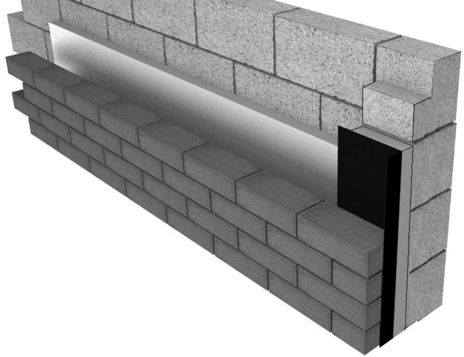
Figure 5.71 Insulated cavity closer fixed to the vertical DPC.
(Source: courtesy of http://www.arcbuildingsolutions.co.uk).
It has become common to insert insulated plastic cavity closers, which reduce heat flow and prevent the passage of moisture across the cavity (Figure 5.72 and Photograph 5.7).

Figure 5.72 Cavity closer.
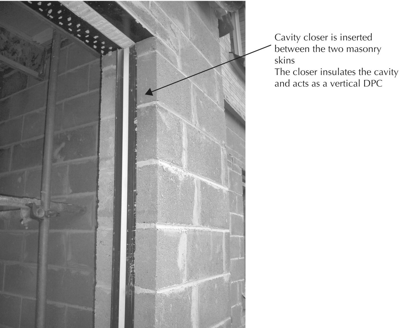
Photograph 5.7 Sealing the cavity in a wall opening: cavity closer.
As an alternative to solidly filling the cavity at jambs with cavity closers, window or door frames were used to cover and seal the cavity. Pressed metal subframes for windows were specifically designed for this purpose, as illustrated in Figure 5.73. With mastic pointing between the metal subframe and the outer reveal, this is a satisfactory way of sealing cavities. With the increasing requirement for insulation, it has become the practice to use cavity insulation as the most practical position for a layer of lightweight material. If the cavity insulation is to be effective for the whole of the wall, it must be continued up to the back of window and door frames, since a solid filling of cavity at jambs would be a less effective insulator and would act as a thermal bridge.
Figure 5.73 Cavity closed with frame.
It has become common practice to use cavity insulation continued up to the frames of openings, and to use cavity closers, as shown in Figure 5.72, to avoid the thermal bridge effect caused by solid fill. Door and window frames are set in position to overlap the outer leaf, with a resilient mastic pointing used as a barrier to rain penetration between the frame and the jamb. With a cavity 100 mm wide and cavity insulation as partial fill, it is necessary to cover the part of the cavity at jambs of openings that is not covered by the frame. This can be effected by covering the cavity with plaster on metal lath, or by the use of jamb linings of wood, as illustrated in Figure 5.74. With this form of construction at the jambs of openings, there is no purpose in forming a vertical DPC at jambs. The advantages of the wide cavity is that the benefit of the use of the cavity insulation can be combined with the cavity air space as resistance to the penetration of water to the inside face of the wall.
Figure 5.74 Jamb lining to wide cavity.
Cills and thresholds of openings
A cill is the horizontal finish to the wall below the lower edge of a window opening. The function of a cill is to protect the wall below a window. Cills are shaped or formed to slope out and project beyond the external face of the wall, so that water runs off. A cill should project at least 45 mm beyond the face of the wall below, and have a drip on the underside of the projection. The cavity insulation shown in Figure 5.74 is carried up behind the stone cill to avoid a thermal bridge, and a DPC is fixed behind the cill as a barrier to moisture penetration. A variety of materials may be used as a cill, such as natural stone, cast stone, concrete, tile, brick and non‐ferrous metals. The choice of a particular material for a cill depends on cost, on availability and, to a large extent, on appearance. As a barrier to the penetration of rain to the inside face of a cavity wall, it is good practice to continue the cavity up and behind the cills.
The threshold to door openings serves as a finish to protect a wall or concrete floor slab below the door. Thresholds were commonly formed as part of a step up to external doors with the top surface of the threshold sloping out to avoid water penetration to the interior. This is no longer common practice because a level entrance is required to allow ease of ingress and egress.
Head of openings in cavity walls
The brickwork and blockwork over the head of openings in cavity walls must be supported by a lintel.
Steel lintels
Most loadbearing brick or blockwork walls over openings, where the cavity insulation is continued down to the head of the window or to the door frame, are supported by steel section lintels. The advantage of these lintels is that they are comparatively lightweight and easy to handle; they provide adequate support for walling over openings in small buildings; and, once they are bedded in place, the work can proceed. The lintels are formed either from a mild steel strip that is pressed to shape, and galvanised with a zinc coating to inhibit rust, or from stainless steel. The lintels for use in cavity walling are formed with either a splay to act as an integral damp‐proof tray, or as a top hat section over which a damp‐proof tray is dressed. Typical sections are shown in Figures 5.75, 5.76, 5.77 and Photograph 5.8.
Figure 5.75 Lintels for cavity walls.

Figure 5.76 Section of pressed steel lintel.

Figure 5.77 Splay lintel.
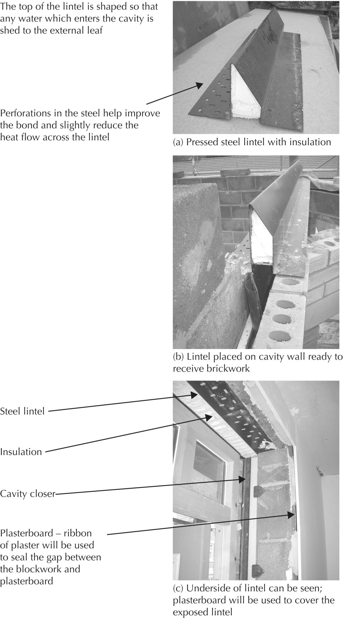
Photograph 5.8 Pressed steel lintels (cavity walls).
For insulation, the splay section and top hat section lintels are filled with EPS. The top hat section steel lintel is built into the jambs of both the inner and outer leaves to provide support for both leaves of the cavity wall, as illustrated in Figures 5.76 and 5.78. The two wings at the bottom of the lintel provide support for the brick outer and block inner leaves over the comparatively narrow openings for windows and doors. Where the cavity is partly filled with insulation, it is usual to dress a flexible DPC from the block inner leaf down to a lower brick course or down to the underside of the brick outer leaf. The purpose of the DPC or tray is to collect any water that might penetrate the outer leaf and direct it to weep holes in the wall.

Figure 5.78 Top hat lintel.
The splay section lintel is built into the jambs of openings to provide support for the outer and inner leaves of the cavity wall over the openings, as illustrated in Figure 5.77. Where the cavity is filled with insulation, there is no need to build in a DPC or tray. Any water that might penetrate the outer leaf will be directed towards the outside by the splay of the lintel. Unless the window or door frame is built‐in or fixed with its external face close to the outside face of the wall, the edge of the wing of the lintel will be exposed on the soffit of the opening. Fairface brickwork supported by steel lintels may be laid as horizontal course brickwork or as a flat brick on edge or end lintel.
Thermal bridging through lintels
Where there is a continuous mass of material across a cavity, the heat flow through that material is likely to be considerable. Even with pressed steel lintels, which incorporate insulation (Photograph 5.8), there is likely to be a continuous piece of steel that links the internal and external environments. Figure 5.79 illustrates how heat energy finds its way across the cavity. The use of two separate concrete lintels is more effective at reducing the heat flow and thermal (cold) bridging.
Concrete lintels
As an alternative to the use of steel lintels, reinforced concrete lintels may be used to support the separate leaves over openings (Figure 5.80). A range of precast reinforced concrete lintels is available to suit the widths of most standard door and window openings, with adequate allowance for building in the ends of lintels on each side of the openings. For use with fairface brickwork, the lintel depth should match the depth of brick course heights to avoid the cutting of bricks around lintel ends. These comparatively lightweight lintels are bedded on walling as support for outer and inner leaves.
Figure 5.79 Thermal bridging: single lintel and separate lintels.
(Source: thermal images courtesy of David Roberts).

Figure 5.80 Concrete lintels.
Cavity trays
In positions of severe exposure to wind‐driven rain, the outer leaf of a cavity wall may absorb water to the extent that rainwater penetrates to the cavity side of the outer leaf. It is unlikely, however, that water will enter the cavity unless there are faults in construction. Where the mortar joints in the outer leaf of a cavity wall are inadequately flushed up with mortar, or the bricks in the outer leaf are very porous and where the wall is subject to severe or very severe exposure, there is a possibility that wind‐driven rain may penetrate the outer leaf to the cavity.
It has become common practice to build in some form of DPC or tray of flexible, impermeable material to direct any water out to the external face of walls. A strip of polymer‐based polythene, bitumen felt or sheet lead is used for the purpose. The DPC and tray shown in Figure 5.80 is built in at the top of the inner lintel and dressed down to the underside of the outer lintel over the head of the window. As an alternative, the DPC tray could be built in on top of the second block course and dressed down to the top of the outer lintel, with weep holes in the vertical brick joints.
Cavity wall insulation
Because the resistance to the passage of heat of a cavity wall by itself is poor, it is necessary to introduce a material with high resistance to heat transfer to the wall construction. Most of the materials (thermal insulators) that afford high resistance to heat transfer are fibrous or cellular, lightweight, have comparatively poor mechanical strength and are not suitable by themselves for use as part of the wall structure. The logical position for such material, therefore, is inside the cavity, either as partial or full fill.
Partial fill
Partial fill construction requires the use of insulating material in the form of boards that are sufficiently rigid to be secured against the inner leaf of the cavity (Photograph 5.9). A 25‐mm‐wide air space between the outer leaf and the cavity insulation should be adequate to resist the penetration of rain, providing the air space is clear of all mortar droppings and other building debris that might serve as a path for water. In practice, it is difficult to maintain a clear 25‐mm‐wide air gap, because of protrusion of mortar from joints in the outer leaf and the difficulty of keeping so narrow a space clear of mortar droppings. Good practice, therefore, is to use a 50‐mm‐wide air space between the outer leaf and the partial fill insulation.

Photograph 5.9 Cavity wall construction partial fill.
To meet insulation requirements with a 100‐mm cavity and partial fill, it may be economic to use a lightweight block inner leaf to augment the cavity insulation. The usual practice is to build the inner leaf of the cavity wall first, up to the first horizontal row of wall ties, then to place the insulation boards in position against the inner leaf. As the outer leaf is built, a batten may be suspended in the cavity air space and raised to the level of the first row of wall ties to stop mortar droppings from falling down the cavity. The batten is then withdrawn and cleared of droppings. Insulation‐retaining wall ties are then bedded across the cavity to tie the leaves and keep the insulation in position. This sequence of operations is repeated at each level of wall ties. The suspension of a batten in the air space and its withdrawal and cleaning at each level of ties do considerably slow down the process of brick and block laying, but it is essential that the procedure be followed.
Care should be taken to ensure that mortar does not fall on cavity ties. Where mortar falls on the tie, a thermal bridge and potential path for moisture to enter the building are created (Photograph 5.10).
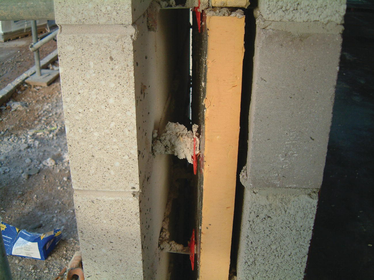
Photograph 5.10 Wall tie covered in mortar – path for moisture and cold bridge.
Insulation‐retaining ties are usually plastic, standard galvanised steel or stainless steel wall ties to which a plastic disc is clipped to retain the edges of the insulation, as illustrated in Figure 5.81. The ties may be set in line one over the other at the edges of boards, so that the retaining clips retain the corners of four insulation boards. The materials used for partial fill insulation should be of boards, slabs or batts that are sufficiently rigid for ease of handling and to be retained in a vertical position against the inner leaf inside the cavity without sagging or losing shape, so that the edges of the boards remain close‐butted throughout the useful life of the building.

Figure 5.81 Partial fill cavity insulation.
Total fill
Insulation that is built in as the walls are raised, to fill the cavity totally, will to an extent be held in position by the wall ties and the two leaves of the cavity wall. To maintain a continuous, vertical layer of insulation inside the cavity, one of the mineral fibre semi‐rigid batts or slabs should be used. Fibreglass and rockwool semi‐rigid batts or slabs in sizes suited to cavity tie spacing are made specifically for this purpose. As the materials are made in widths to suit vertical wall tie spacing, there is no need to push them down into the cavity after the wall is built, as is often the procedure with loose fibre rolls and mats, which can displace freshly laid brick or blockwork.
The most effective way of insulating an existing cavity wall is to fill the cavity with some insulating material that can be blown into the cavity through small holes drilled in the outer leaf of the wall. The injection of the cavity fill is a comparatively simple job. The complication arises in forming sleeves around air vents penetrating the wall and sealing gaps around openings. Glass fibre and granulated rockwool of EPS beads are used for the injection of insulation for existing cavity walls. These materials can also be used for blowing into the cavity of newly built walls.
Insulation materials
The materials used as insulation for the fabric of buildings may be grouped as inorganic and organic insulants.
Inorganic insulants are made from naturally occurring materials that are formed into fibre, powder or cellular structures that have a high void content, such as, for example, glass fibre, mineral fibre (rockwool), cellular glass beads, vermiculite, calcium silicate, magnesia and compressed cork. Inorganic insulants are generally incombustible, do not support the spread of flames, are rot‐ and vermin‐proof and generally have a higher U‐value than organic insulants. The inorganic insulants most used in the fabric of buildings are glass fibre and rockwool – in the form of loose fibres; mats and rolls of felted fibres and semi‐rigid and rigid boards; batts and slabs of compressed fibres; cellular glass beads fused together as rigid boards; compressed cork boards; and vermiculite grains.
Organic insulants are based on hydrocarbon polymers in the form of thermosetting or thermoplastic resins to form structures with a high void content, such as, for example, polystyrene, polyurethane (PUR), isocyanurate and phenolic. Organic insulants generally have a lower U‐value than inorganic insulants, are combustible, support the spread of flame more readily than inorganic insulants and have a comparatively low melting point. Organic insulants most used for the fabric of buildings are EPS in the form of beads or boards, extruded polystyrene (XPS) in the form of boards and PUR, isocyanurate, and phenolic foams in the form of preformed boards or spray coatings.
The materials normally used for cavity insulation are glass fibre, rockwool and EPS, in the form of slabs or boards, in sizes to suit cavity tie spacing. With increased requirements for the insulation of walls, it may well be advantageous to use one of the more expensive organic insulants such as XPS, PIR or PUR because of their lower U‐value, where a 50‐mm clear air space can be maintained without greatly increasing the overall width of the cavity.
With growing attention to building in a greener and more sustainable manner, some new materials are starting to be used. These include products made from natural materials such as hemp and sheep’s wool, and products made from recycled products, such as newspaper.
Sheep’s wool thermal insulation products are made of 100% wool, or a mixture of wool and other fibres. Wool has a thermal conductivity of around 0.04 W/mK, with 100 and 200 mm depths of insulation, giving U‐values of 0.40 and 0.20, respectively, and is better suited to roof insulation (see also Chapter 6) or to the wide cavities afforded by timber‐framed construction. Cellulose thermal insulation products are made from recycled newspapers, typically with a thermal conductivity of around 0.036 W/mK.
For calculating the thickness of insulation required in a wall, the following formula is useful as a reference:
- R = d/λ = thermal resistance (m2K/W)
- λ = thermal conductivity (W/mK)
- d = thickness of material (in metres)
- U = U‐value = thermal transmittance (W/m2K)
- Hence, the thermal transmittance (U‐value) is expressed as U = 1/ΣR.
The thermal resistance of a cavity wall is calculated as follows.
- If a wall requires a U‐value of 0.35 W/m2K, the resistance required can be calculated by transposing the following formula:
- U‐value = 1/ΣR
- Thus, ΣR (required) = 1/U‐value
- Hence, the thermal resistance required = 1/0.35 = 2.86 m2K/W
Component/element Thickness (metres), ‘d’ Thermal conductivity (W/mK), ‘λ’ Thermal resistance (m2K/W), ‘R’ = d/λ External surface resistance (RSo) – – 0.04 102‐mm brick outer leaf 0.1025 0.84 0.122 50‐mm cavity 0.050 0.27 0.185 100‐mm blockwork aircrete 0.100 0.11 0.909 13‐mm plasterboard 0.013 0.50 0.026 Internal surface resistance (RSi) – – 0.13 ΣR – – 1.421 - Thermal resistance required = 2.86 m2K/W
- Therefore, 2.86 − 1.421 = 1.439 m2K/W
- Transposing the formula, R = d/λ
- Thus, R × λ = d
- 1.439 × 0.03 = 0.043 m, or 0.043 × 1000 = 43 mm
Additional resistance to be provided by insulation = 2.86 − 1.421 = 1.439 m2K/W. Assuming that insulation with a thermal conductivity of 0.03 W/mK is used, the thickness of insulation required will be obtained by rearranging the formula R = d/λ. Thus, R × λ = d, using the simple multiplication 1.439 × 0.03 = 0.043 m, or 0.043 × 1000 = 43 mm. Hence, the required thickness of insulation is 43 mm, or the closest convenient thickness available from a manufacturer, say, 45 or 50 mm of insulation board.

Figure 5.82 Cavity wall built to Passivhaus standards.
(Source: adapted from http://www.greenbuildingstore.co.uk).
Achieving low U‐values
With different combinations of cavity wall construction, it is relatively easy to achieve low U‐values (Figure 5.82). The combination of lightweight blocks, insulants with low thermal conductivity and airtight construction can achieve U‐values of less than 0.2 W/m2K. For example, lightweight blocks are now available with thermal conductivities of 0.11 W/mK (R‐values for 100 mm and 140 mm = 0.1/0.11 = 0.909 m2K/W and 0.14/0.11 = 1.273 m2K/W, respectively), which, used in combination with a PIR of 0.022 W/mK (R‐value for 100 mm = 0.1/0.022 = 4.55 m2K/W), regular brick thermal conductivity of 0.6 W/mK (R‐value for 102.5 mm = 0.102/0.6 = 0.17 m2K/W), internal surface resistance of 0.12 m2K/W and external surface resistance of 0.06 m2K/W, can achieve low U‐values of 0.16 W/m2K.
Other materials such as aerogel insulants offer much lower conductivities and can achieve low U‐values with a thinner cavity/wall section. These are currently relatively expensive as compared to other insulants, and therefore tend to be used only when space is at a premium.
Some properties are now being built to Passivhaus standards using masonry walls. One example is the Denby Dale passive house, constructed with an outer leaf of stone, an inner leaf of blockwork, and 300 mm of low‐conductivity DriTherm ridged slabs of water‐repellent glass wool (0.037 W/mK). Extra‐long (Teplo basalt fibre) wall ties, 200–425 mm long, which can suit cavities up to 300 mm in width, were used to tie the skins together. Each wall tie has a thermal conductivity (0.7 W/mK) of 7 mm dia, with a sand finish to provide a mortar key and penetrated across the three 100‐mm boards of insulation to provide the structural tie between the walls. The low‐conductivity wall ties avoid cold bridging and the risk of condensation. With such long protruding cavity ties, end caps are a must during construction to avoid the risk of injury to the eyes or other skin punctures (Photograph 5.11a–c).

Photograph 5.11 (a) Cavity wall built to passivhous standards, 300‐mm mineral wool insulation; (b) 300‐mm mineral wool cavity insulation, built to passivhous standards, basalt Teplo low‐conductivity cavity ties and mineral wall used to seal cavity with adjoining property; (c) 300‐mm cavity wall built to passivhous standards, ready to receive blown fibre insulation EPS cavity closer.

Figure 5.83 Sound, fire and heat flux flow through unsealed cavities.
Preventing heat loss, flanking sound and ensuring fire integrity across party walls formed with a cavity
Sealing cavities in party walls
Cavity barriers are used to reduce flanking sound and also to reduce air circulation within the cavity (Figure 5.83). By closing the cavity with barriers, air movement from one part of the cavity to the other is less likely to occur, and because open spaces within the cavity are reduced, the effect of convection currents, which can manifest as a result of differing temperatures, is also minimised. All parts and edges of the cavity must be sealed, including the top and bottom of the cavity.
Cavity barriers are also required to withhold the passage of smoke and fire. Gaps in the cavity barriers will allow fire to pass around them or flash through the voids, as fire follows sources of oxygen. It is important that junctions be designed and detailed to prevent air flow within the cavity, and also that the barriers be fitted carefully and then independently checked.
If there are any imperfections in the building envelope that connect to the cavities, cold air will enter the building and circulate around the structure and its connecting cavities. The ingress of cold air (especially when exposed to high wind pressure) and the escape of the warmer air will lead to thermal bypasses, cause cold draughts and result in cold spots within the building (as the cold air cools the fabric). Where cavities are not required to be ventilated, they should be sealed to prevent thermal and acoustic exchanges and to reduce the potential penetration of smoke and fire.
Effective U‐values of party walls separated by cavities
The heat flow in relatively stable conditions typically ranges from 0.5 to 0.7 W/m2K, if the cavity is not sealed. Unless edge sealing is used in party walls, a default U‐value of 0.5 W/m2K must be used (see Part L of the Building Regulations). With effective edge sealing, the U‐value is assumed to be 0.2 W/m2K. Only a fully filled insulated cavity, effectively sealed at all edges, can be assumed to have a U‐value of 0.0 W/m2K (Figures 5.84, 5.85, 5.86, 5.87, 5.88, 5.89, 5.90, and 5.91).
Figure 5.84 Cavity barrier in an uninsulated cavity.

Figure 5.85 Cavity barrier in a partial fill cavity.
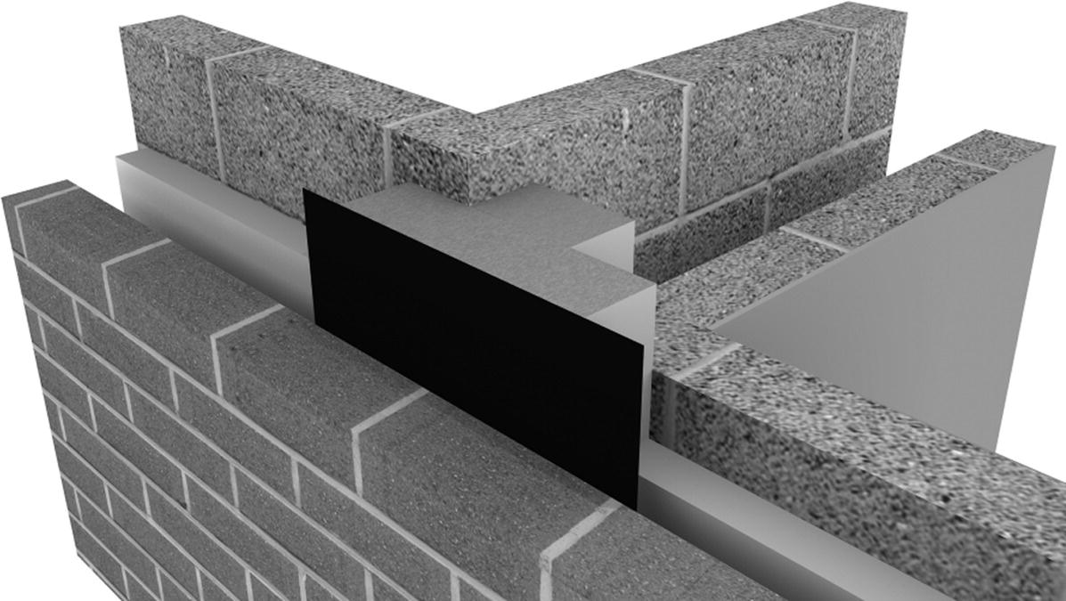
Figure 5.86 Partial fill cavity, party wall junction sealed with a tee cavity closer.
(Source: courtesy of http://www.arcbuildingsolutions.co.uk).

Figure 5.87 Cavity barrier in fully filled cavity.
Figure 5.88 Cavity and party wall sealed with a cavity closer.
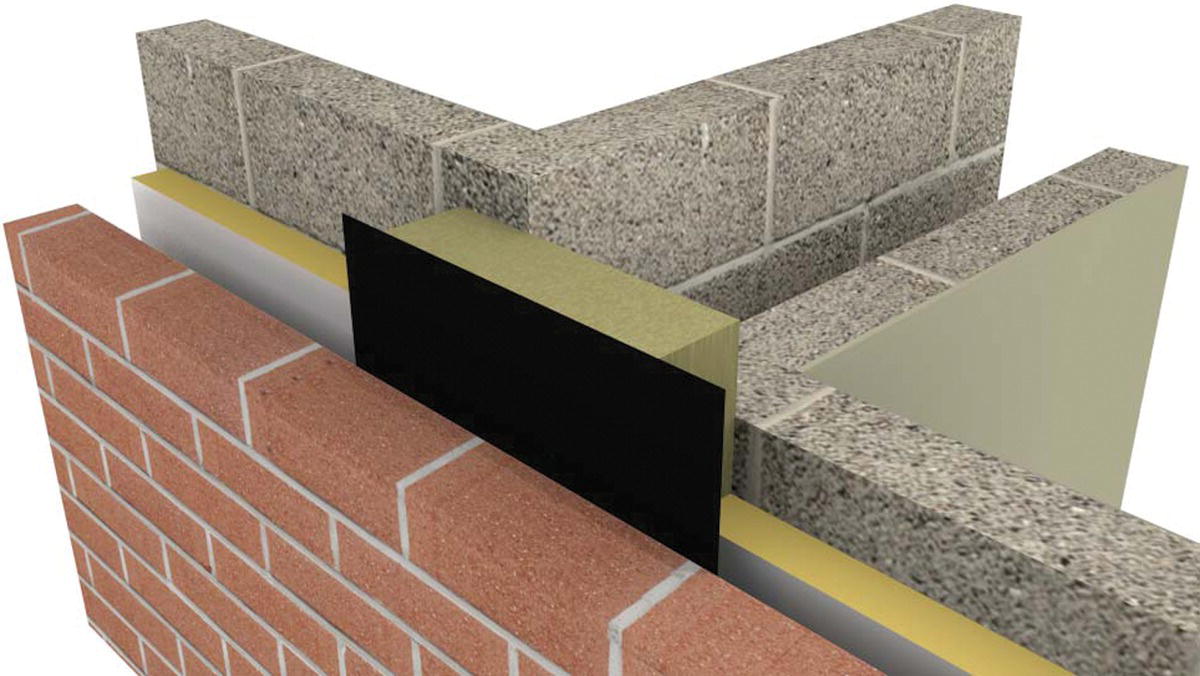
Figure 5.89 Cavity sealed with a cavity closer.
(Source: courtesy of http://www.arcbuildingsolutions.co.uk).

Figure 5.90 Cavity sealed with a cavity sealer.

Figure 5.91 Cavity sealed at edges of the external wall and party wall with cavity closers.
5.8 Internal and party walls
Internal walls may either be loadbearing or non‐loadbearing. Non‐loadbearing walls are usually referred to as ‘partition’ walls, although care is required because the term is used very loosely and may refer to loadbearing walls. When carrying out work to existing buildings, it will be necessary to determine the nature of internal walls, and whether or not they are loadbearing, prior to carrying out any construction or demolition work. In loadbearing masonry construction, the internal walls were usually constructed from brick or blockwork, often supporting floor joists or ceiling joists. Current practice is to use stud walls made of timber or metal, faced with plasterboard, which are quicker to erect and easier to move/adjust at a future date (see Barry’s Advanced Construction of Buildings for details of framed construction). This is common practice for both upper floor and ground floor partition walls. Masonry may still be used, depending on the functional requirements of the wall – for example, to provide additional acoustic damping or to perform a loadbearing function.
Party walls
The requirement of Part E of Schedule 1 to the Building Regulations is that walls that separate a dwelling from another building or from another dwelling shall have reasonable resistance to airborne sound. Where solid walls of brick or block are used to separate dwellings, the reduction of airborne sound between dwellings depends mainly on the weight of the wall and its thickness. A cavity wall with two leaves of brick or block does not afford the same sound reduction as a solid wall of equivalent thickness, because the stiffness of the two separate leaves is less than that of the solid wall and, in consequence, is more readily set into vibration. The joints between bricks or blocks should be solidly filled with mortar, and joints between the top of a wall and ceilings should be filled against airborne sound transmission.
Approved Document E provides practical guidance on meeting the requirements of the Building Regulations in relation to walls between dwellings by stipulating the minimum weight of walls to provide adequate airborne sound reduction. For example, a solid brick wall, 215 mm thick, plastered on both sides, should weigh at least 300 kg/m2 (including plaster); a similar cavity wall, 255 mm thick, plastered on both sides, should weigh at least 415 kg/m2 (including plaster); and a cavity block wall, 250 mm thick, plastered on both sides, should weigh at least 425 kg/m2 (including plaster).
Care should be taken to ensure that the wall and surrounding structure are suitable to achieve the level of sound insulation required. Consideration needs to be given to impact sound, sealing air paths (to prevent airborne sound) and controlling flanking transmission. Thermal insulation also needs to be considered.
In flats and houses separated by party walls, it is essential that fire be prevented from passing from one dwelling to another. The Building Regulations outline the requirements of compartment walls (walls that restrict the passage of fire from one area to another).
The Party Wall Act 1996 provides a framework of statutory regulations that must be complied with when undertaking works that affect adjoining property. The three main issues that are addressed are: the construction of new walls on boundaries between adjoining lands with different owners (Section 1: ‘New building on junction’); repairs and modifications to existing party walls (Section 2: ‘Repair, etc. of party wall: rights of owner’); and excavation near to the neighbouring buildings or property (Section 6: ‘Adjacent excavation and construction’). In order to comply with the Act, a notice must be served on adjoining owners if works covered by the Act, such as work to party walls or boundaries, are planned. Where there is disagreement between owners, the parties are required to resolve the matter through a dispute‐resolution procedure.
5.9 Straw wall construction
Straw is a renewable and viable building material, being plentiful and inexpensive. The annual harvest of grain from barley, flax, oats, rye and wheat results in the generation of a considerable quantity of stalks (straw), which is mostly underutilised or even wasted. From an environmental perspective, straw contains carbon, which is trapped in the construction, rather than being released through burning/disposal. The embodied energy in the straw bale construction is also low as compared to conventional walls, requiring little processing and transportation (as use is usually local or regional). Straw is an organic tube made of cellulose that is structurally strong in compression, and is thus well suited to a number of applications in construction. Straw was first used to reinforce mud and prevent it from cracking, and then as a building block with the invention of the mechanical baler. Straw has reasonably good thermal insulating properties and, because bales are approximately 600 mm thick, a straw bale wall has high thermal resistance. Straw is currently used as a building material in bale form, or as a pressed panel.
Straw bale construction
Straw bale construction is a relatively old construction method that has become fashionable in recent years, especially in the American Southwest. The drive for a more sustainable approach to the construction of buildings has also resulted in considerable interest and practical application in many countries, including the UK. Straw bale buildings offer a simple and practical method of creating a building with excellent performance characteristics. Super‐insulated walls (thermal and acoustic), simple construction, low build costs and the conversion of an agricultural by‐product into building material are all attractive characteristics. With the limited skills required to build a straw bale house, the technique tends to appeal to self‐builders and community build groups who can realise low‐cost, energy‐efficient dwellings, creating a relatively organic addition to the community and, at the same time, helping to generate income for local farms. Well‐detailed, properly constructed and maintained straw bale houses have a long life, which is comparable with other types of construction. Straw bale construction has also been used in conjunction with other materials in more complex designs for houses and commercial buildings. Here, the economies of scale are not available to contractors; thus, straw bale walls tend to be more expensive than more traditional approaches.
Advantages of straw bale construction
In addition to the simplicity of design and ease of adaptability, there are a number of performance advantages that a straw bale house has over conventional loadbearing masonry or framed construction.
Straw bale structures are highly fire resistant. The compressed bales contain enough air to provide good insulation values, but, because they are compacted firmly, they do not hold enough air to permit combustion. Combined with render and plaster surface finishes, a high degree of fire resistance is possible. The type of straw and the moisture content of the bales will mainly determine the thermal characteristics of the wall. With infill construction, the frame will also be a determining factor of the overall thermal performance of the wall. Acoustic insulation is considerably better than a conventional wall structure.
Closely packed straw bales, covered with render on the outside face and plaster on the inner face, provide good air leakage control. Coupled with simple geometric design, well‐built and well‐maintained straw bale construction provides a building with very little air leakage. The render and plaster finishes can be left unpainted and are inexpensive to maintain. The construction cost of a straw bale wall should be significantly less than that for a comparative wall with the same thermal and acoustic performance.
Disadvantages of straw bale construction
The main disadvantage of straw bale construction relates to concerns over durability, particularly moisture‐related damage. Straw bale construction is most suited to dry climates (hot and cold). In the UK, the construction of straw bale houses is a relatively recent innovation; thus, it is difficult to state with any certainty what the durability of the structure will be over the longer term. As more straw bale buildings are built in the UK and more research is conducted into their durability, designers and builders should have more information from which to make informed decisions.
Fungal rot represents the greatest threat to the life of a straw bale building; thus, careful detailing is required to prevent the straw bales from becoming wet. Foundations and roof construction are critical in preventing unwanted rain and moisture penetration, and the construction of the wall must be done in such a way as to avoid any possibility of interstitial condensation. Fungi and mites can live in wet straw; therefore, the bales must be bought when they are dry, kept dry until needed and then sealed into the wall construction with plaster and render to eliminate any chance of access for pests. Paint for interior and exterior wall surfaces should be permeable to water vapour, so that moisture does not get trapped inside the wall. Services, especially sealing around outlets, need special attention.
Straw bale walls are considerably thicker than the more traditional construction methods (at least double), and, hence, where land is at a premium, a straw bale house will provide less internal space for the same external dimensions as compared to a traditional construction. This may be of little concern in rural locations. The appearance of straw bale buildings may not always appeal to a more urban environment, although there are a few examples of straw bale construction being used in densely populated urban environments, usually in conjunction with other materials as part of a composite construction.
Selection of straw bales
Automatic straw balers create tight blocks of straw that provide a relatively easy‐to‐manoeuvre building block. Sizes of bales vary depending on the baler; however, typical bale dimensions and weight when dry are:
- Two‐wire bale: 450 × 350 × 900 mm, approximately 25 kg
- Three‐wire bale: 600 × 400 × 1050 mm, approximately 35 kg
Although the smaller‐sized bale is easier to handle, the medium‐sized three‐wire bale provides better structural, thermal and acoustic performance. Larger cubical and round bales are also available, but these require lifting by mechanical means. There have been moves in the US to develop a ‘construction‐grade’ straw bale. Ideally, bales should be twice as long as they are wide to simplify and maintain a running bond in the courses.
Straw bales should be purchased immediately after the harvest, when they are abundant, fresh and dry. Dealing directly with a farmer is the cheapest and perhaps most reliable method of selecting the best‐quality bales, since quality is largely judged on visual appearance and touch. Transportation to the building site will need to be addressed, perhaps independently of the arrangement with the farmer if the bales are to be transported out of the local area. Straw bale merchants provide an alternative source of supply and will have an established transport infrastructure and storage facilities. Once again, the selection of the bales, especially if sourced from more than one farmer, is an important consideration.
Bales should be tied tightly with polypropylene string or bailing wire and should not twist or sag when lifted. All bales should be uniformly compacted and contain thick, long‐stemmed straw; any bales comprising short, thin straw should be rejected. Old and/or damaged bales should be rejected. If practical, the construction of a straw bale building should be undertaken immediately after the main grain harvest, when the bales are fresh and dry, with bales transported to the site, positioned and protected from the weather as quickly as possible. If this is not an option, then the bales should be selected and stored under dry, ventilated, conditions. Bales should be tested for moisture content, which must be 14% or below when purchased and when used for building. All bales must be stored under dry conditions until required for building purposes. Protection of the bales from the weather is also necessary during construction.
Foundation construction and site drainage
The base of a straw bale construction must be kept dry at all times; thus, the manner in which the straw bale interacts with the foundation will be a crucial factor in determining the durability of the wall. The position of the lowest straw bale in relation to the finished ground level and the detailing of the external wall finish at this junction are particularly important. Similarly, site drainage must be designed to get water away from the base of the walls as quickly as possible (Figure 5.92).

Figure 5.92 Vertical section through a straw bale wall.
Guidance on the minimum distance between the finished ground level and the lowest bale position varies from around 225 mm upwards to 300–450 mm. Knowledge of local rainfall patterns, the extent of the roof overhang in relation to the height of the wall and the ground finish adjacent to the wall will be determining factors. As a general guide, the bales should be positioned at least 450 mm off the finished ground level to avoid splashback of rain, bouncing off the ground and on to the face of the wall. The material under the straw bales should be good‐quality stone, engineering brick or dense blockwork. The DPC should be positioned between the solid foundation and the timber base or sole plate. The manner in which the external render is finished at the junction of foundation and wall is also important. A drip should be formed at the bottom of the render to help throw any water that runs down the wall off and away from the base of the wall.
Care should be taken to not compromise the site drainage through inappropriate surface finishes. The ground around the structure must be well drained, and kept dry with adequate surface and below‐ground drainage. The position of the water table and the history of the proposed site with regard to flooding should be investigated, and appropriate decisions taken to protect the construction from damp and/or wet conditions. Self‐draining foundations are one method of helping to keep the base of the wall free of water. Vermiculite is placed above the cavity tray. Below the cavity tray, the cavity should be filled with drainage gravel, and weep holes provided at regular intervals (Figure 5.93).
Roof construction
The design and construction of the roof is another critical area. The roof should be constructed with a large overhang to provide protection to the wall below from rain and snow. Leaks in the roof and/or inappropriate detailing at the wall‐to‐roof junction will compromise the long‐term durability of the structure. A large roof overhang on single‐storey buildings will also provide good protection to the base of the wall. Roof pitch is another consideration, with steep pitches and a good‐quality roof covering to facilitate the rapid discharge of rainwater from the roof considered important for the durability of the roof. Timber roof construction is the usual method, with the roof loads transferred to the foundations via the loadbearing straw bale wall or via the timber frame construction (described further in more detail). Roof coverings may be of reed thatch, tile or lightweight finishes, with lightweight roof structures and coverings preferred for loadbearing straw bale walls.
Wall construction
The main principle of straw bale design is based on the use of full bales as a building module – simplicity is key. Half‐bales will be required for bonding purposes, the same principle as that for brick and block wall construction. Bales smaller than a half‐size should not be used, because of their lack of compressive strength. Careful planning is required before any drawings are finalised, simply because the actual size of bales varies between suppliers. Once a bale supplier (and, hence, dimension) has been determined, it is possible to design and detail the building plan and also the opening sizes (doors and windows) and their positions within the wall. The main principles relating to the strength and stability of the wall are similar to those for loadbearing or framed construction. Where possible, doors and windows should be selected to suit the bale module size, or be manufactured/built to suit the bale module. When using loadbearing straw bale construction, there will be some settlement of the wall after the roof has been completed. The straw bales must be sealed against the weather and pests. External surfaces are finished in lime render (stucco). Internal surfaces are plastered. The render and plaster provide an attractive surface finish, which also adds to the structural integrity of the wall.

Figure 5.93 Straw bale wall to foundation detail.
Loadbearing straw bale construction
In loadbearing straw bale construction, the straw bale walls directly support the loads from the roof. The quality of the bales is an important consideration. Hazel pins are used to tie the bales together, two per bale from the fourth course upwards, with staples used to tie the bales at changes of direction, such as corners. The bales are often tied together tightly with threaded metal rods, wire or plastic straps, which helps to compress them and hence minimise settlement of the bales when the roof structure is added. For small buildings with relatively short lengths of wall, such as small single‐storey houses, there may be no need for additional support. For long walls, it will be necessary to provide a system of vertical posts at intervals of 10 m (or less) to help support the weight of the roof, in which case the infill method may be more suitable. The straw bales will provide lateral restraint at the corners; thus, a minimum return of at least two bales is recommended before any openings are made in the walls for doors or windows. This is a similar principle to that adopted for brick and block walls.
Settlement of the straw bales under load, which may be irregular, must be considered in the design. Settlement in a seven‐bale‐high wall may be up to 50 mm, and is difficult to predict because the extent of settlement will depend on the density of the bales (which varies between bales) and the amount of loading applied to them. Thus, for practical reasons, it is necessary to measure the opening sizes after the main structure is complete, and to install doors and windows late in the construction process (after the initial settlement of the bales).
Mortar bale
A structural mortar made of Portland cement and sand is applied between the straw bales to create a lattice structure. When dry, the lattice forms a structural framework between the bales, and thus provides a form of backup, should a straw bale fail. Bales are finished with stucco on the external face and plastered on the interior to protect the bales, and also to provide an attractive finish. The stucco and plaster also add to the structural integrity of the wall. Some designers and builders may feel that resorting to cement will compromise their environmental ideals.
Infill straw bale construction
‘Non‐loadbearing’, ‘post and beam’, ‘framed’ and ‘infill’ are terms used to describe a framed wall construction with the bales bearing their own weight. The wall‐framing members carry the weight of the roof. This method is better suited to larger structures. The bales are attached to each other by piercing them with bamboo, hazel or metal reinforcing bars, and securing them to the timber framework. With the infill technique, the settlement of the straw bales may be less (less load on them), and hence the settlement of the bales is less of a concern than with a loadbearing construction. Restricting the straw bales to an infill function only may be a less risky approach to straw bale construction. If there is a problem with any of the straw bales the structural integrity will not be compromised. Framed construction provides an opportunity to construct the frame before the grain harvest; thus, fresh bales can be taken directly from the field and installed. This helps to ensure that dry bales are used, and removes the need for storage and unnecessary weather protection.
Straw and clay building
A traditional and durable construction method is to use a ‘batter’ of clay and water stirred into loose straw to produce a straw‐reinforced clay mud. The mixture is packed tightly into a lightweight timber ladder framework to create partition walls, or infill panels for framed wall construction.
Pressed straw panels
Pressed straw panels are made by compressing straw under temperature to produce a panel made of 100% straw. The combination of compressed straw, recycled paper lining and adhesive will form a board that generally complies with BS 4046. The result is a low‐cost, versatile product with environmental benefits. The panels can be used as a self‐supporting, non‐loadbearing partition system, and also for roof decking. The technique was first introduced to the UK and developed into a sophisticated straw board product by Stramit, in Suffolk, UK. Pressed straw panels may also be used in roofs and floors. Research and development is currently being conducted by several companies and research organisations into the use of pressed straw panels for use in a structural capacity.
5.10 Earth wall construction
While earth or unfired clay brick walls are commonly used in very warm, dry, climates, earth wall construction is also gaining increasing interest in the UK. Rocks and soils are some of the most economic building materials, available locally and with a long record of use in vernacular buildings in the UK – for example, in cob construction. There has been renewed interest in the use of earth as a building material in the UK, mainly associated with the drive for a more environment‐friendly approach to construction. There remain a number of concerns about durability, but, when detailed to suit the climate and topography of the site, there is no reason why earth‐based construction cannot provide an alternative to more traditional materials and methods. The most common method used in the UK is earth‐sheltered structures, with growing interest in adobe and rammed earth. To reduce transportation costs, and the associated pollution, earth should be used from the building site, and additional materials sourced locally. It may be an obvious point, but earth construction will be specific to the locale, soil condition, techniques and materials available. There will be a strong reliance on the extent of local knowledge among the workers.
Earth‐sheltered construction
Earth‐sheltered buildings are an energy‐efficient and environmentally conscious approach to construction that may suit certain sites and some clients. The concept of burying the building under the ground, or at least covering a significant proportion of the building with soil, is not new. Various designs exist, ranging from buildings completely buried beneath the ground to buildings that have one or more walls protected by the earth.
When the entire structure is buried, the term ‘underground’ structure is used. When earth is banked up (‘bermed’) against an external wall, this is known as a ‘bermed’ structure. A bermed structure may be built above, or partially above, natural ground level. In the majority of cases, the roof will be covered with earth and vegetation to form a green roof. The vegetation (grass or sedums) will help to reduce erosion and provide an attractive finish. Three generic house designs have been developed from the use of underground and/or bermed construction. They are:
- Courtyard (or atrium) design. An underground structure planned around a central atrium, from which rooms are accessed, and which forms the focal point of the house. Some designs are based on an open courtyard, which provides natural ventilation but poses some problems with removal of surface water and snow. Atrium designs are built with a glazed roof over the courtyard, which, depending on the design, can also help to provide some natural ventilation. Plan forms tend to be circular, ovoid or hexagonal in nature.
- Elevational design. A bermed structure, usually with a glazed south‐facing wall. While the glazed facade is exposed, the other walls are covered with earth. The south‐facing wall allows penetration of daylight and thermal gain, while also providing an opportunity for natural ventilation. Skylights can be used to alleviate the problems of poor light and poor air circulation further into the plan. To reduce the depth of the house, the south (and north) faces are considerably longer than the east and west walls, creating a long, thin house. It is common to construct a curved elevation to the south.
- Penetrational design. Again, a bermed structure that covers the entire house, with the exception of doors and windows. The house is usually built on a flat site, with the earth bermed around the entire structure. This allows the opportunity for cross‐ventilation and for the provision of natural light entry to all rooms.
In the UK, earth‐sheltered construction has been employed on a small number of commercial buildings, but this tends to be favoured by clients wanting a bespoke house design. The primary concern is with protection from moisture. Careful choice of site (e.g. topography, groundwater position, soil type), along with the provision of adequate drainage at and below ground and waterproofing to walls, is a crucial factor. Earth‐sheltered structures need to be well designed and constructed, and designers and contractors with experience in this type of work should be used.
A naturally sloping site is the best location for an earth‐sheltered building. The extent of the dig required to excavate a suitable area will be determined by the angle of the slope; thus, a moderately steep site is usually preferable to a gently sloping site. Soil type is another determining factor. Granular soils compact well and are permeable, which allows groundwater to drain away. Sites with cohesive soils (such as clays) should be avoided, because the clay will expand when wet and has poor permeability. Site investigation is also necessary to establish the height of the water table (the lowest level of the building must be above the water table). Areas in which radon gas naturally occurs should be avoided, and special measures may be required where the site is heavily contaminated.
Advantages of earth‐sheltered structures
An earth‐sheltered house provides several benefits over more traditional structures. The biggest advantage is that the building is protected from the weather and hence is not subject to deterioration by, for example, solar radiation or wind damage. In very exposed locations, protection from adverse weather may be a considerable benefit. Protecting the building with earth will reduce or even eliminate the need for regular painting, cleaning of gutters and repair. Thus, maintenance is considerably less onerous for the majority of earth‐sheltered designs.
The earth provides natural insulating properties to the structure, providing a relatively stable indoor temperature that is less affected by external air temperature fluctuations. Thus, less energy is required to maintain a stable internal temperature. The earth also provides considerable sound dampening, in addition to that provided by the structure of the building.
Earth‐sheltered structures will blend into the landscape and may be an ideal solution in areas where the visual appearance of a structure would cause a problem. This does not mean, however, that approval from the local town planning department will be forthcoming, since other factors, such as land use and access, will also need to be considered.
Disadvantages of earth‐sheltered structures
There are a number of potential disadvantages associated with earth‐sheltered structures. Exclusion of moisture is perhaps the most obvious. Waterproofing and tanking is a primary concern, and often carries a relatively high initial cost. Surface water and underground drainage is key. Seasonal or regular surface water flows must be channelled away from the structure. Underground drainage should be designed to remove water (and water pressure on the walls) quickly. Regular maintenance of drainage channels to avoid blockages is also essential if problems are to be avoided.
The initial cost of an earth‐sheltered structure can be as much as 20% higher than a comparable structure built above the ground. Exact figures will depend on the nature of the ground and topography of the site (e.g. gently or steeply sloping). However, there may be considerable cost savings made during the life of the building, which must be considered in a whole life costing approach.
Earth‐sheltered houses tend to be characterised by high levels of humidity; therefore, air exchange is important. Some designs may also result in pockets of stale air, unless some form of air flow is introduced. Ensuring adequate air flow can be achieved through the use of passive or mechanical ventilation systems. Passive ventilation can be provided through vented skylights, which are required to get natural light into the internal spaces. Linking the air exchange system to an earth‐to‐air heat exchanger may help to keep energy costs to a minimum.
Repairs and remedial work to the structure of the building may be expensive, since it is difficult to get to the walls without removing a great deal of earth. This places additional emphasis on the quality of the detailing and the quality of the work undertaken on site. Careful and systematic inspection of the waterproofing work as it proceeds is essential.
Materials
The most commonly used material for the retaining walls is concrete. Reinforced in‐situ concrete and/or prefabricated concrete can be used. Alternatively, masonry (brick, block, stone) can be used, reinforced with steel bars. Attention must be given to joints (i.e. between precast concrete units) to ensure the walls remain watertight. In addition to their strength, walls must provide a good surface for waterproofing and thermal insulation (where required). Waterproofing to the walls can be achieved with a number of systems. The main materials are:
- Rubberised asphalt. Sheets are applied directly to walls and roofs and have a long life expectancy.
- Plastic sheets. The integrity of these sheet systems relies on the seams between the sheet materials. The seams must be formed and sealed properly; otherwise, the membrane will leak. A variety of sheets with different material properties are available.
- Liquid PURs. Usually used in places where it is difficult to apply a membrane. Sometimes applied over the external side of insulation.
- Bentonite. A natural clay that expands on contact with water and forms a barrier to moisture penetration. Formed into panels attached to walls, or spray‐applied in liquid form with a binding agent.
Thermal insulation
Insulation is usually placed on the exterior face of the walls, after the waterproofing system has been completed. In this way, the heat generated, captured and absorbed within the earth‐sheltered envelope is retained by the building’s interior. Rigid insulation sheets help to protect the waterproofing against punctures from sharp stones in the soil. Thin protective boards are often used as a barrier between the insulation and the earth.
Adobe
Adobe is compressed earth, rammed into moulds or pressed into blocks while damp, and sun‐dried to form a building block or brick. Adobe is a common construction method in many parts of the world (mainly places with a dry climate). The best adobes are made from soil that is high in clay content. Mechanical presses can be used to form adobe blocks directly from the building site’s soil. These blocks are then used to build loadbearing (or infill) walls, laid without mortar. Blocks are laid in a walling bond, with the connecting surfaces wetted with water to help provide a bond between the individual units when dry. The walls are then rendered (stuccoed). Compaction of the earth is critical, and over‐compaction can lead to fracture of the material. Scientific analysis of the soil is therefore crucial.
Adobe and rammed earth walls absorb solar heat during the day and radiate heat back into the air at night, thus providing a comfortable and relatively constant internal temperature. Hence, adobe tends to be used in dry and hot locations. Both exterior and internal adobe walls provide good thermal mass and can form part of a passive design. The principles of weather protection and durability of earth are similar to that of straw – namely, protection from moisture. In damp climates and areas of heavy rainfall, it might be prudent to use adobe only for internal walls.
Rammed earth
‘Rammed earth’ is a term used to describe the mixing of cement and earth, which is then packed into wall forms with a pneumatic tamper – hence the term ‘rammed’ earth. The result is a material that resembles a sedimentary rock, with compressive strengths about half that of concrete. The strength of the material will vary, depending on the ratio of cement to soil (and soil type); thus, the testing of batches is necessary to determine the loadbearing capacity of the resulting wall. Since it uses soil from the building site, rammed earth can prove to be a relatively cheap material, with reasonable environmental credentials. The use of the material is similar to that described for concrete walls. By increasing the thickness of the walls, the loadbearing capacity may be increased.
Hempcrete
Hemp is a low‐impact, sustainable plant material that is easy to grow, reaching heights of up to 4 m. The fibres are separated from the woody core, shredded and then graded for use in construction. The fibres are then mixed with quicklime (calcium oxide) to provide a homogeneous material that can be used as insulation and non‐structural walling material. When used within a timber frame, hempcrete has good insulation properties, and, with the application of an air barrier, it can achieve the same standard of airtightness as other building materials.
Hempcrete can be sprayed onto a background to provide an insulation layer. Alternatively, it can be prepacked into prefabricated panels that can be delivered to site and erected in the same way as other off‐site‐engineered panels, or the panels can be placed in situ between the timber frames. Formwork is used to provide the temporary mould for the hempcrete, which can be removed after 24 hours. The drying times of hemp vary, and the typical conductivity of hempcrete is 0.07–0.09 W/mK. For a 500‐mm‐deep wall, in a timber frame, it is possible to achieve a U‐value of 0.21 W/m2K.