3
Core Architectural Concepts: Integration and Cryptography
This Book Comes with Free Online Content
With this book, you get unlimited access to web-based CTA exam prep tools like flashcards and exam tips.
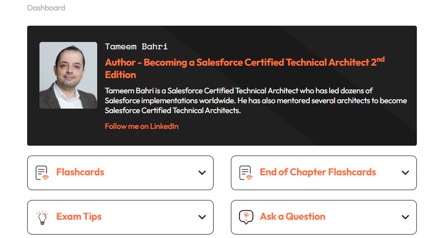
Figure 3.1 – CTA online resources dashboard
To unlock the content, you’ll need to create an account using your unique sign-up code provided with this book. Refer to the Instructions for Unlocking the Online Content section in the Preface on how to do that.
Accessing the Online Content
If you’ve already created your account using those instructions, visit packt.link/ctabookwebsite or scan the following QR code to quickly open the website.

Figure 3.2 – QR Code to access CTA online resources
Once there, click the Login link in the top-right corner of the page to access the content using your credentials.
In this chapter, you will continue to discover the general architectural concepts that a Salesforce CTA should be familiar with. In today’s world, it is rare to come across a single implementation where Salesforce is completely isolated. In most cases, Salesforce will become the heart of the enterprise’s business transformation process, which means that it must relate to dozens of other new and existing applications. The cost of integration is sometimes overlooked or underestimated, despite several studies pointing out that around 25-35% of the total project cost would likely be spent on integration.
Coming up with the right integration architecture is crucial to the success of a Salesforce project. Moreover, securing the internal and external integration interfaces is becoming more and more important, especially with the progressive move toward API economy and data monetization. The Salesforce Architect is expected to be able to design a secure and scalable integrated solution.
In this chapter, you will discover general architectural concepts about integration and cryptography. Building that breadth of knowledge will help you dive deeper into Salesforce-specific topics in the chapters to come. In this chapter, we are going to cover the following topics:
- Integration in the enterprise: Understanding the landscape
- Introducing common integration styles
- Discussing different integration tools
- Exploring modern integration approaches
- Cryptography: Understanding the general concepts
- Cryptography algorithm types and use cases
Now, let’s explore the first bullet in the list.
Integration in the Enterprise: Understanding the Landscape
The digital enterprise landscape is continuously becoming more sophisticated. Gone are the days when the enterprise used to have less than 10 systems covering most of its business processes. Today’s enterprises have hundreds, if not thousands, of different applications that are bought, built in-house, or combined. This is in addition to a set of legacy systems that are still surviving the axe. Nowadays, it is very common to find that an enterprise has dozens of websites, multiple instances of ERP systems, and many other departmental applications, in addition to several data warehouses or lakes.
One of the reasons why enterprises end up in such situations is the complexity associated with building business applications. Building a single application that runs all business processes is nearly impossible. Maintaining it, adapting to day-to-day business challenges, and requesting changes are even more challenging. Breaking business functions into smaller chunks of applications has always made sense. It provides the business with enough flexibility and agility to move at the pace they need, rather than being bound by the technical boundaries of a bigger all-in-one solution. Moreover, it gives the business the opportunity to pick and choose the best suite of applications that best serve their needs. This would mean combining the best customer relationship management (CRM) system with the best order management system (OMS) and enterprise resource planning (ERP) solution.
In the past 20 years or so, vendors have offered focused applications for specific core functions. There has been the continuous addition of functionalities to existing applications, which has caused some sort of functionality spillover. For example, several pieces of customer care software have had extensions to include a limited billing functionality due to the difficulty of drawing clear functional separations between systems. For instance, if a customer raises a dispute for a bill, will that be considered something to be handled by customer care or billing applications?
On the other hand, users do not really care about these boundaries or the systems that are behind the scenes. They expect a business function to be executed, regardless of the system or systems involved in delivering it. For example, when a customer places an order online, this will likely require coordination between multiple systems to deliver several functionalities, such as checking the history or credit score of the customer, checking inventory, computing tax, creating the order, fulfilling the order, handling shipment, sending the bill, collecting payment, and more. These processes can span many systems, but from the customer’s perspective, that was a single transaction.
To support these distributed functionalities, which are still expected to work as a coherent business process, these applications need to be integrated in an efficient, secure, scalable, and reliable fashion.
The typical enterprise integration needs are as follows:
- Get the right information: Get precise knowledge of a particular piece of information created by different systems and enterprise business processes. This knowledge must be structured in a way that can support other business needs.
- Get that information to the right place: This requires mechanisms to handle information transactions across heterogeneous environments, which may be based on different technology stacks and reside on different servers/hardware and operating systems.
- Get that information at the right time: Ideally, this requires distributing the information in real time to reflect the actual state of a particular data entity.
- Flexibility and embracement of change: This is done to adapt to external factors, such as market demand, customer shift of behavior, new legislation, or a shift in social philosophy.
- Coordinate business processes: This is a challenging operation that may require modeling the enterprise business’s processes, how they are interlinked, and what kind of information they exchange. This may require having a deep understanding of the business and certain knowledge of the enterprise.
So, what makes a good integration architecture? You will find that out in the next section.
Integration Architecture Design Principles
Like any complex technical architectural topic, there are several considerations and consequences that you need to keep in mind while designing the target integration strategy and architecture. Integration is one of the key areas where sub-optimal designs could have a significant impact on the overall solution.
The main decision points are usually as follows:
- Native integration: Simply put, if you can develop a single standalone application that can fulfill all business needs on its own, without any need to collaborate with any other application, then you can avoid a lot of complexity driven by integration requirements. However, this is not something you can normally achieve. Several attempts to extend an application so that it includes other functionalities can end up creating a complex system that is hard to manage and maintain, slow to react to market needs, and hard to adjust to meet new business requirements.
This problem exists in the Salesforce world as well, although in a more limited way. Many Salesforce products are natively integrated, with many considered the best in the market, and have the ability to deliver different user experiences. For example, Salesforce communities provide a native solution to exposing a customer portal that is natively integrated with your CRM.
Salesforce communities offer a very good sharing model and an easy way to control the look and feel of the community itself. It makes sense to favor that over a solution where you need to build a custom-made customer portal over a technology, then figure out a way to integrate it with Salesforce in a secure and compliant way. Moreover, using the native integration keeps the doors open for using other natively integrated features in the future.
- Simplicity: This goes beyond the integration architecture. Simplicity is an aim that architects and developers should always strive for. Avoid complicated solutions as much as possible and always keep the golden 80-20 rule in mind.
Fulfilling 80% of use cases using a simplified architecture should be preferred over targeting a solution that covers 100% of use cases using an over-complicated architecture. Keep your integration code simple and tidy. In some use cases, you may still need to introduce some complex modules to deliver highly sophisticated functionalities.
- Application dependencies: Integrated applications should have minimal dependencies on each other. This allows solutions to evolve independently without being tied to each other’s roadmaps. It also allows you to replace an application completely without it impacting the other integrated systems.
Tightly coupled applications have many dependencies on each other and rely on many assumptions regarding how each of them works. When an application is modified, the assumptions could change, which would, in turn, break the integration.
In a loosely coupled integration, the integration interface is specific enough to deliver a particular functionality but generic enough to allow for a change if needed.
- Timing: Ideally, the integration architecture should aim to minimize the duration between the moment an application is sending data and another application is receiving it. The integration architecture should aim to share small chunks of data as frequently as possible, rather than waiting to exchange a huge block of data that may not necessarily be related.
Data sharing latency should be taken into consideration while designing the architecture. The longer a data exchange process takes, the more likely it will become more complex and prone to other challenges, such as a change in the data’s state. Bulk data exchanges can still be used for the right use cases, such as archiving operational data.
- Synchronous versus asynchronous: In a synchronous process, a procedure waits until all its sub-procedures finish executing. However, in an integrated environment, where the integrated applications might be on different networks or might not necessarily be available at the same time, you may find more use cases where the procedure does not have to wait for all its sub-procedures to conclude. It simply invokes the sub-procedure and then lets it execute asynchronously in the background, making use of the multi-threading ability available in many of today’s applications.
- Integration technology: Selecting the right technology is essential. Depending on the integration techniques available, there might be higher dependencies on specific skill sets, hardware, or software. This might impact the speed and agility of your project.
- Data format: Data that is exchanged between different applications must follow a pre-agreed format. In the enterprise world, this is unlikely. Therefore, the integration process must have an intermediate step where the data is translated from one format into another.
Another related challenge is the natural evolution of data formats. Flexibility to accommodate the changes and extensions of a data format plays a great role in defining the flexibility of the integration architecture.
- Data versus functionality: Integration is not necessarily about sharing data. The integrated applications could be looking to share functionality. Think of the use case where one application needs to invoke a particular functionality in another system, such as checking for a particular customer’s credit score. There will likely be a set of parameters being sent to the other end to facilitate the logic of the remote process. Invoking remote functionalities can be difficult and could have a significant impact on how reliable the integration is. As a Salesforce Architect, you need to be aware of specific integration patterns, and you need to understand the limitations of the platform. You will cover this in Chapter 9, Forging an Integrated Solution.
There are several considerations that an architect should consider when designing an integration strategy or a distributed solution. Now, you need to understand what key integration styles are available and what they should be used for.
Introducing Common Integration Styles
When designing an integration architecture between two or more systems, the key challenge is how to achieve that. There are some common integration styles that architects should be familiar with. You need to have basic knowledge of them and understand how and when to use each style. In today’s world, some of these integration styles have evolved and are used as part of modern enterprise integration platforms. Next, you will become familiar with the file transfer, unified datastore, remote procedure invocation (RPI), messaging, and mashup integration styles.
File Transfer
In this integration style, applications produce a file containing the data that other applications would consume. This file is normally in a format that can be read by all the target systems and shared in a repository that can be accessed by all concerned systems. These systems are responsible for transforming the file into any other format they are expecting, while the file’s producer is responsible for generating the data files at regular intervals based on business needs.
One of the challenges with this approach is based on the produced file types, as some applications might not be able to produce data in a standard format, such as XML. This is particularly true for legacy applications. The timing of this approach and its limited scalability has always been an issue, while reliability and the ability to spot and report exceptions in a timely manner are another. Moreover, this approach is only good for exchanging a snapshot of data at a given point in time. It lacks the agility, scalability, and speed required by today’s integrated applications.
In today’s world, the customer is expected to receive a payment receipt immediately after completing a payment. They will receive an order confirmation email once the order has been submitted, with another email confirming the dispatch date. Failing to deliver a similar or better user experience means that your overall solution is falling short of today’s digital customer experience, which is considered one of the most important success factors for digital businesses. However, this approach is still valid for the right use cases, particularly when there is a need to replicate reporting data from a legacy system or an external system that does not support APIs and does not grant you access to its data via any other mechanism.
Unified Data store
Think of it this way: if a set of integrated applications is designed to rely on a common database, then they are pretty much integrated in a consistent fashion all the time. If one application updates the data, the other systems will get access to the latest updated version of the data as soon as they attempt to retrieve it. Only cached data might be out of date. Moreover, there is no need to do any data transformations as all the involved systems are built to work with the given underlying structure.
The challenge with this approach is in terms of high dependency between the applications themselves and between them and the database. Moreover, with today’s ever-changing landscape of technologies, expecting all systems to work with a unified database is not realistic. This approach was very popular in the early days of distributed systems, particularly with the client-server architecture. Today, it receives a bit of a boost from the concept of data lakes. Many enterprises are experimenting with a concept where all their operational data is centralized in a data lake, with a rich set of APIs on top to provide a flexible interface for other applications to integrate with.
Realistically, this approach has many challenges, including the fact that today’s enterprise applications are designed and built to work with their own databases. Attempts to change are very expensive and time-consuming. Moreover, they could cause the original application to lose key functionalities or end up creating a performance bottleneck.
Remote Procedure Invocation
This is an integration style that is used when there is a need for more than just exchanging data. As you might have noticed, the two previous approaches replicate data from one system to another. However, that might not be enough. Applications usually take specific actions once the data they rely on has changed. For example, a change of order status in application A might trigger the creation of a legal entity in application B. To simplify this process and reduce application dependencies, RPI has been introduced, where the logic of creating that legal entity in application B will be encapsulated and made available for other systems to invoke.
Historically, there were several technologies that implemented the RPI concept, such as CORBA and .NET remoting. In today’s world, the preferred technologies are web services. If you are not familiar with web services, you can think of them as a set of encapsulated functionalities built using commonly used open standards and protocols. The main functionality of a web service is to facilitate exchanging data between systems. It also inherits some of the RPI concepts since the invoked web services can, in turn, invoke another action in the target application. Web services rely mostly on two common standards, SOAP and REST. The latter is considered more modern due to its small data footprint and its simplicity as it can be easily invoked by clients, including a browser or a mobile app.
The concept of web services is sometimes confused with the concept of application programmable interfaces (APIs). An API is a software interface that is used to expose the logic and functionalities of a particular application to other applications. This allows unrelated applications to integrate and interact without knowing how each of them is built. The mix between the two concepts comes from the fact that many modern systems have built their own APIs in the form of web services, using standards such as SOAP and REST. Some have even gone further and exposed these web services to the public, such as AWS and Google.
Messaging
Messaging is an asynchronous style of integration where two or more systems are loosely integrated via a message bus, which contains several virtual pipes that connect a sender to a receiver (called channels), and message routers, which are components that determine how to navigate the channels’ topology to deliver the message to the right receiver.
In this style, integrated systems are not necessarily required to be up and running at the same time. The asynchronous nature of this style also means that it is more capable of scaling to support highly demanding applications. However, the message bus itself might end up becoming a bottleneck if it is not designed in a way that enables smooth auto-scaling. This integration style provides the principles of the enterprise service bus (ESB), which is highly adopted in today’s enterprises. You will cover ESBs and other integration tools later in this chapter. The principles of this style were also the basis of the event-driven integration architecture and the rise of event store and stream-processing platforms such as Apache Kafka.
Mashup
Mashup is a technique that is relatively more recent as it relies mainly on browsers. In a mashup, a web application/website utilizes data from other web applications/websites by embedding it into the UI. This integration style is sometimes referred to as UI-level integration.
You have likely encountered mashups multiple times before. Think of applications that use Google Maps to embed a map into their web pages. Mashups usually rely on web services, but they can also simply be an iFrame (Salesforce has a functionality that enables UI-level integration with other third-party web applications called Canvas).
Most mashups are visual, although some could be invisible to the user (such as tracking cookies, which track the behavior of web users across multiple websites and devices). Visual mashups (such as Google Maps) are interactive by nature and are heavily used in today’s web applications to enrich the overall user experience.
Now that you have explored the different integration styles, have a look at some of the modern integration approaches and tools. As a Salesforce Architect, you need to have a solid understanding of the differences between these tools to select the right one for your project.
Discussing Different Integration Tools
Before discussing some of the common types of integration tools available today, you need to understand why these tools are necessary. As a Salesforce Architect, you are expected to guide the client and the integration team when it comes to selecting the right set of tools that support the agreed integration strategy. You should be able to challenge sub-optimal design decisions based on valid logic and rationale. Picking the wrong tool or opting for shortcuts without considering their potential impact could prove to be very costly, and this might impact the project/program in multiple ways and become a major risk to the success of your Salesforce implementation. During the CTA review board, you are always expected to justify why you selected your integration tools.
Historically, a common way to integrate two applications together is through a direct channel with no third-party app or mediator in between. This can be done with point-to-point (P2P) integration. Now, let’s take a closer look at it.
Point-to-Point Integration
As an architect, you need to understand the capabilities and limitations of P2P integrations and why you would likely need an integration tool (on some occasions, it is also called a piece of middleware) in an enterprise context. This section describes various P2P connections.
Unique Channel Establishment
A unique channel is established between each pair of applications that need to interact with each other. The number of unique channels required to connect N number of systems can be calculated using the formula N(N-1)/2. For example, if you need to connect three systems through a one-way-direction interface, you will need three unique channels. But to link 10 different applications, you would need 10*(10-1)/2 = 45 unique channels. All of this is assuming there is a one-way direction, of course. Each of these channels must be developed, documented, tested, and maintained on a regular basis.
Despite that, this cost should not be considered the full cost of the P2P approach. The real cost will start to show up on the macro level, as the cost to add additional systems to the landscape or to connect additional systems to it is not linear. Calculate how many new integration channels would be needed to add three more applications to the previously mentioned landscape. Practically, enterprises will not necessarily expect that the new applications will be linked to every other application. However, the cost is still unpredictable, and depending on the nature of the new applications and their business functionalities, the cost could rise dramatically.
The hub-and-spoke approach requires much fewer channels. In this approach, each application is a spoke and only connected to the hub for any given transaction. This results in a much more flexible landscape, with the ability to easily predict the number of new channels required to hook an additional system.
The following diagram compares the number of channels required for both approaches:

Figure 3.3 – Number of unique channels in both P2P and hub-and-spoke connections
Each of the unique integration channels is expected to handle any required data transformations. This will require your developers to know both integrated applications well. Moreover, the logic for the data transformations is going to be hidden within each channel, reducing the ability to reuse or manage them centrally.
Process Orchestration
Process orchestration needs to be handled on the channel level as well. This includes any exception handling and retries mechanisms. For example, consider a scenario where you have an order intake application, A, which collects the customer and order information from an online web page. It then passes that to an order management application, B, which stores the customer data and the order data separately.
Assume that both applications have secure APIs that can be invoked by other applications. In this case, application A is going to invoke application B’s customer creation API, and once it receives a response that the process has been completed successfully, it will invoke the order creation API to create an order related to the recently created customer. The integration channel must be built to handle the potential failure of customer creation for any reason, including the unavailability of application B. It will likely need to implement a retry mechanism with a comprehensive exception handling and logging capability.
A notification mechanism would also be valuable to have. A rollback capability would be desirable. Remember that all of this will have to be repeated for every single P2P integration channel in the landscape. This will require a massive amount of effort and would inevitably reduce the overall reliability of the integrated solution.
Overall Reliability
The overall reliability of the integrated solution is an important topic to consider, particularly while using P2P connections. Imagine an integrated solution of three different applications, that is, A, B, and C. For a particular business process, application A needs to communicate with application B, which, in turn, is going to communicate with application C. When utilizing P2P connections, these can be thought of as three systems connected sequentially. This means that the overall integrated solution’s reliability can be calculated using this formula:
R = A1-R * A2-R * A3-R * … * AN-R
Here, AN-R is the reliability of the application, N.
For this example, assume that the applications had the following reliabilities:
- A1-R = 0.9
- A2-R = 0.8
- A3-R = 0.5
Here, the overall solution would have a reliability of 0.9 × 0.8 × 0.5 = 0.36.
For the sake of simplicity, it is assumed that the reliability of each of the given applications does not change with time and does not get impacted by any external factors (for example, a reduced server capacity or network lag). Historical failure rates for each of these applications are also not factored in. Using a hub-and-spoke approach instead of P2P would significantly increase the overall reliability of your solution as it simplifies the connections. The hub itself can turn into a bottleneck, but you have fewer things that could go wrong.
Limited Capabilities
Since all data transformations and process orchestrations are taking place on each individual channel, many of these channels end up as straightforward integrations. While simplicity is an architectural goal that should be aimed for, the limited technical capabilities imposed by P2P would effectively limit the business’s ability to introduce complex business differentiator services.
Turns IT into a Blocker
Over time, P2P integrations would inevitably become difficult to maintain and support. Teams will worry about attempting to change anything in them, and the process of deploying any new feature or even a hotfix will become increasingly slow and costly. This would effectively turn the IT department into a blocker rather than an enabler for the enterprise.
High Dependencies
Typically, tightly coupled integrated applications have high dependencies on each other. You came across this earlier, in the context of reliability and cost of ownership. However, it can also be extended to other dimensions.
Consider a use case where three out of 10 of the integrated applications mentioned earlier have reached their end of life and need to be replaced. Due to the high dependencies in a P2P-based landscape, this will likely have a direct impact on all the other applications in the landscape.
Scalability
Due to all the previous reasons, it is easy to understand why P2P is not the right option to design a scalable enterprise solution.
You need to keep all the considerations discussed in this section in your mind while proposing your integration architecture. In the CTA review board exam, you are expected to come up with the best technical solution. In real life, you need to be able to articulate the pros and cons to your stakeholders and walk them through the different options they have, as this will help them select the most suitable one for them. You will cover more Salesforce-specific integration topics in the chapters to come.
Now that you understand the challenges with P2P connections, you will discover the different available integration tools. Some of them support the hub-and-spoke integration architecture by nature.
Extract, Transform, and Load
In this method of data integration, the data is copied from one or more data sources into a destination data store that does not necessarily share the same structure as the data source(s). This integration method follows some principles from the file transfer integration style and the more modern ETL tools, and uses some of the principles inherited from the messaging style:
- Data extraction involves accessing one or more data sources and extracting data from them.
- Data transformation includes all activities that take place on the data before it is delivered to its destination. The activities include data cleansing, data formatting, data enrichment, data validation, and data augmentation.
- Data loading includes the processes required to access and load the data into the final target data store.
ETL tools may stage the data into a staging area or staging data store to run complex transformations on it, such as de-duplication, custom logic, or data enrichment by looking up external reference data. Normally, the staging data store would co-exist with the ETL tool on the same server to provide the quickest possible response time. The three ETL processes take time, so it is common to have them scheduled or running in an asynchronous fashion. Most modern ETL tools can be scheduled to run a particular job every few minutes.
Some ETL tools can also expose a triggerable endpoint, which is simply an HTTP listener that can receive a message from specific authorized senders to trigger one or more ETL jobs. For example, a listener can be exposed to receiving a specific type of outbound message from a particular Salesforce instance. Once the outbound message is received, the listener triggers one or more ETL jobs to retrieve or update data in Salesforce, as well as other systems.
Most of today’s ETL tools come with built-in connectors for different types of application databases, such as Salesforce, Microsoft Azure, Amazon Redshift, Amazon S3, and SAP. In addition, they also come with adapters to generic database APIs, such as Open Database Connectivity (ODBC) and Java database connectivity (JDBC). Some even provide connectors for the file transfer protocol (FTP) and the SSH file transfer protocol (SFTP). These connectors allow you to access a particular application database in an optimized fashion. For example, the Salesforce connector could be built to automatically switch between using Salesforce’s standard REST API, the Salesforce SOAP API, or the Salesforce Bulk API, depending on the operation that is been executed and the amount of data being dealt with.
Today, several ETL products are provided in a SaaS fashion. In this case, you need to understand how the ETL tools can connect to a database behind a firewall. The enterprise’s hosted applications and database would normally reside behind the enterprise firewall. Most enterprises have strict regulations that prevent such resources from being exposed. These are known as demilitarized zones (DMZs).
A DMZ is a physical or logical sub-network that is used by the enterprise to expose external-facing materials and content—mainly to the public, who are untrusted users. Resources in these DMZs can be accessed by cloud-based applications. However, this is not how cloud-based ETL tools get access to the enterprise’s locally hosted applications. One of the most popular ways to achieve this is by installing a client application on the enterprise’s local network. This is a trusted application provided by the ETL tool product provider, and its main duty is to facilitate communication between the enterprise’s local applications and databases and the cloud-based ETL tool. The security team will still need to configure the firewall to allow the client to communicate back and forth with the cloud-based ETL tool.
ETL tools are suitable for data replication operations. They are designed and built to provide a robust and scalable service, since they can deal with millions, and even billions, of records. ETL tools are also ideal for data replications that require a lot of time, such as replicating media files. They are flexible and easy to work with.
As a Salesforce Architect, you need to know about some of the popular ETLs that are used today. You also need to understand the limitations of out-of-the-box tools such as Salesforce Data Loader, which is too simple to be categorized as an ETL tool. Some of the most popular ETL tools that are used today are Informatica PowerCenter, Informatica Cloud, Talend, Jitterbit, and MuleSoft (although MuleSoft is normally considered more of an ESB tool, it supports both integration methods).
Enterprise Service Bus
Enterprise service bus is the name given to a particular method of data integration where the different applications are integrated via a communication bus. Each application only communicates with the bus. This decouples the applications and reduces dependencies, so systems can communicate without knowing details about how other systems operate. This integration method follows principles from the messaging integration style, as well as the RPI style. ESB tools have developed this concept even further and currently support different architectural concepts, such as microservices, API-led connectivity, and event-driven architectures. You will cover all these concepts later in this chapter.
ESBs support both synchronous and asynchronous types of communications, which makes them ideal for integrations operating on the business logic layer, where RPI is a key capability to look for. ESBs also utilize built-in connectors to connect to different types of applications and data stores, similar to ETL tools. The connector here would also transform the data from the source system format into the bus format. Considering that ESBs are usually stateless, the state of each message in the bus is included as part of the message itself. While the data is traveling through the bus, it is considered to be in a canonical data format. A canonical data format is simply a model of the data that supersets all other models of the same data in the landscape. This canonical data is normally translated into target data models. The cloud information model (CIM) is a good example of a canonical data model.
Note
Describing CIM is beyond the scope of this book, but becoming familiar with it is strongly recommended.
ESBs can handle complex orchestrations. For example, an application, A, might be sending customer details to the ESB, which, in turn, would communicate with multiple external applications to do a real-time credit check, followed by an invocation to the CRM system, to start a customer onboarding journey. The customer onboarding journey then generates a unique customer ID that is returned to application A with a success message. ESBs can handle complex orchestrations and can use a supporting database as temporary storage or as a cache for some data. The database would normally co-exist with the ESB tool on the same server to provide the quickest possible response time.
The ESB also handles any kind of required data cleansing, data formatting, data enrichment, data validation, and data augmentation, as well as translations from/to different data formats. For example, an application, A, sends data in the intermediate document (IDoc) format to the ESB, which receives it, augments it with other data coming from a lookup/reference data source, and then translates that into the formats expected by the recipients, such as XML, CSV, and JSON.
ESBs can also provide multiple interfaces for the same component, which is particularly useful for providing backward compatibility, especially for web services. ESBs are normally designed to be scalable and capable of handling a high load of traffic, and several modern ESBs are offered today in a SaaS fashion with an option to host them locally. Due to their stateless nature, ESBs are not considered ideal for long-running operations, such as replicating a massive amount of data between systems or moving large media files.
As a Salesforce Architect, you need to know about some of the popular ESBs that are in use today. You also need to understand when and why to propose utilizing an ESB as part of your landscape. Make sure you fully understand the differences between ESBs and ETLs, as well as which is good for what. Also, make sure you understand why, in most cases, enterprises should utilize a piece of middleware of some sort instead of P2P connections. Make sure you understand the ideal use cases for ESBs to recognize whether they are utilized in the most optimal way in a given implementation or not. ESBs and ETLs are very common in Salesforce solutions, and you will come across several examples where they are proposed to be used in the chapters to come. Some of the popular ESB tools that are used with Salesforce today are MuleSoft, webMethods Integration Server, IBM Integration Bus, TIBCO ActiveMatrix Service Bus, and WSO2 Enterprise Integrator.
Reverse Proxies
A reverse proxy is the opposite of a forward proxy; while a forward proxy is used as an intermediary by the client to connect to a server, a reverse proxy is something the server (or servers) puts between itself and potential clients.
For the end client, any retrieved resources would appear as if they originated from the proxy server itself, rather than the server or servers that are behind it. A reverse proxy is often used to provide a more secure interface to deal with untrusted clients (such as unauthorized internet users), as well as shielding the other applications behind it that might lack the ability to handle the excessive load or are unable to provide the right security measure required (such as the inability to support HTTPS).
A reverse proxy can provide capabilities such as transforming HTTPS requests into HTTP, handling cookies and session data, transforming one request into multiple requests behind the scenes, and then combining the responses and buffering incoming requests to protect the shielded servers from excessive load. Some providers of reverse proxy products are VMware, Citrix Systems, and F5 Networks.
API Gateways
API gateways are historically used to protect your internal web services (or APIs—remember that the two terms can be used interchangeably in the web context as most modern APIs are offered as web services). The enterprise’s internal APIs might not be designed to handle topics such as authentication and scalability, so an API gateway would provide a layer on top to protect the APIs, as well as enabling a set of other functionalities, such as monetizing the APIs, providing real-time analytics, and protection against denial of service (DOS) attacks.
API gateways are very similar in concept to the reverse proxies and can be described as a special type of reverse proxy. On some occasions, you might have both in your landscape, where the API gateway sits behind the reverse proxy that handles load balancing. API gateways can normally be configured via an API or a UI. On the other hand, reverse proxies are normally configured via a config file and require a restart to use a new set of configurations. API gateways also provide advanced API functionalities, such as rate limiting, quotas, and service discovery.
As a Salesforce Architect, you need to know about some of the popular API gateways that are in use today, such as MuleSoft, Microsoft’s Azure API Management, Google (Apigee), and IBM API Management.
Stream-Processing Platforms
Stream-processing platforms are systems designed to get the most out of parallel processing. This allows them to fully utilize the computational capabilities of their server. Ideally, they are utilized in event-driven integrations. This process inherits some principles from the messaging integration style. Stream-processing platforms are often referred to as message queue platforms. You will cover the event-driven integration approach shortly.
Stream-processing platforms can handle huge amounts of incoming data since they are designed to make use of elastic scaling. They are also easy to encapsulate in containers, which makes them easy to deploy on different platforms, including the cloud, on-premises, or hybrid environments. Due to their capabilities and nature, stream-processing platforms are considered ideal in use cases where there is a need for a massively scalable messaging platform, such as an IoT server. Some of the most popular stream-processing tools in use today are Apache Kafka, Amazon Kinesis, Redis, and RabbitMQ. Salesforce Heroku supports some of these technologies, such as Kafka.
With that, you have covered the challenges that may arise from P2P connections, as well as the need for middleware. You have also discovered different types of middleware with each reflecting several values. You will now discover some modern integration approaches, such as service-oriented architecture (SOA), microservices, API-led connectivity, and event-driven architecture.
Exploring Modern Integration Approaches
The technological landscape is ever-changing, and as a Salesforce Architect, you deal with modern tools and technologies every day. It is very important to align the topics you covered earlier with today’s modern integration approaches. Some of these approaches have lost popularity, but their concepts are still the basis of other modern approaches.
To fully understand the modern integration approaches and be able to lead discussions with your client, enterprise architects, and integration architects about the most appropriate integration strategy to use, you need to have a wide knowledge of today’s modern integration approaches, in addition to a deep and solid understanding of their foundations. Sometimes, technology enthusiasts get carried away with new concepts and terminology. While staying up to date with the latest market trends is important, as a senior architect, you need to understand which of these approaches is most suitable for your client and the project at hand.
Service-Oriented Architecture
SOA is an approach to software development that aims to encapsulate business logic into a service that gets the most out of reusable code. Each service contains the code and data integrations required to fulfill a particular business use case, for example, placing a shopping order or onboarding a new customer.
These services are loosely coupled and utilize an ESB to communicate with each other. This means that developers can save time by reusing existing SOA services across the enterprise.
SOA services are logical representations of particular business activities with clear, specific outcomes. They are provided as a black box for consumers, who do not need to worry about how these services are working. These services can consist of multiple underlying services.
SOA emerged in the late 1990s and was the basis for other modern integration approaches, such as microservices and event-driven architecture. Some critics of SOA mention challenges regarding its performance and maintainability and the difficulties associated with designing it to the right level of granularity.
A simplified SOA-based architecture would look as follows:
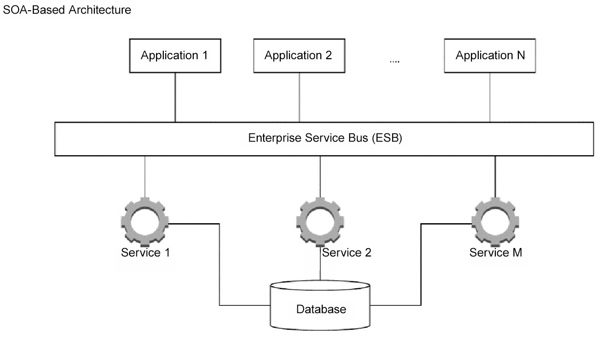
Figure 3.4 – Example of an SOA-based architecture
Microservices
Microservices are a modern interpretation of SOA. They are made up of loosely coupled and reusable components with clear functionalities and outcomes. Rather than communicating through an ESB, microservices directly communicate with each other. The services can use different technologies and protocols.
The microservices architecture is geared toward the cloud. It utilizes development and operations (DevOps) concepts to allow decentralized small teams to take complete ownership of a particular service, deliver its functionality using their preferred technology, and rapidly release it to the enterprise using lightweight containers.
Microservices are typically used as building blocks for other enterprise applications. They are fine-grained services and have access to their own data stores to retrieve the data they need. Microservices are not supposed to access the same data store/database as this would create a dependency between them and other data stores. The microservices principles favor encapsulation and independency over reusability; redundant code is considered an accepted side effect.
Microservices have become popular since their introduction in 2014 due to their relationship with DevOps concepts. Due to the similarity between SOA and microservices, it is useful to understand some of the key differences between these integration approaches:
- Synchronous calls: Reusable SOA services should be available throughout the enterprise via the use of synchronous protocols such as SOAP or REST APIs. Synchronous calls are less preferred in the microservices architecture as they may create real-time dependencies, which may cause latency. An asynchronous approach is preferred, such as publish/subscribe, as it enhances the resilience and availability of the services.
- Communication: SOA services utilize ESBs to communicate, which makes the ESB a performance bottleneck. Microservices are developed independently, and they communicate directly using different protocols and standards.
- Reuse: SOA is all about increasing reuse, whereas in the microservices architecture, this is less important. This is because achieving some reusability at runtime could create dependencies between the microservices, which reduces agility and resilience. In microservices, duplicating code by copying and pasting is considered an accepted side effect to avoid dependencies.
- Data duplication: In SOA, the services can directly access and modify data in a data source or application. This means that multiple SOA services would likely be accessing the same data store.
Microservices always aim to reduce dependencies. A microservice should ideally have local access to all the data to deliver its expected functionality. This means that there might be a need to duplicate some data. This also means that the data could be out of sync between different services. Data duplication adds a considerable amount of complexity to the design and potential usage of microservices, so it must be balanced against the expected gains from the microservice’s independence.
- Granularity: Microservices are designed to be specialized and fine-grained to execute one specific task, whereas SOA services reflect business services and range from small to bigger enterprise-wide services.
- Speed: Speed is one of the weaker sides of SOA due to several factors. Microservices are lightweight and more specialized, and usually utilize lightweight communication protocols, such as REST. They generally run faster than SOA services.
A simplified microservices-based architecture would look as follows:
Figure 3.5 – An example of a microservices-based architecture
API-led Architecture
The API-led architecture is an API strategy where all external and internal services are exposed as managed APIs, regardless of how they were implemented (microservices, SOA services, web services driven out of a monolithic application, or based on other architectures). Managed APIs, in today’s modern terms, do more than just provide governance capabilities such as security policies, throttling, versioning, and automatic service discovery. The principle has extended beyond this to include developer portals where they can experiment with APIs before using them, productivity tools, and a mechanism to register and pay for API usage. In this approach, APIs are usually organized into three different layers:
- System APIs: These APIs are used to access core systems and services. They provide a simplified insulating layer between the service consumer and the underlying system or service.
- Process APIs: These APIs are used to interact with, transform, and shape the data coming from the underlying system APIs or from other process APIs, effectively breaking down data silos. They have no dependency on the source systems where the data came from, nor on the target systems where the data will be delivered. Both system APIs and process APIs can be used to connect to existing microservices as well as other enterprise services, depending on the use case.
- Experience APIs: These APIs are used to allow easy access and data consumption for the end user or application. They typically communicate with one or more process APIs to deliver specific functionality.
Microservices are known to create many endpoints, which are normally difficult to control and monetize. The API-led architecture aims to create an API strategy that governs the way the different enterprise services interact with each other, as well as with external consumers, by utilizing the capabilities of lightweight standards such as REST and combining them with modern API gateway capabilities.
Microservices are typically consumed by applications. The API-led architecture aims to turn these applications into a smaller and lighter set of APIs. This can help enterprises take steps toward the API economy. For example, an enterprise could create a set of APIs on top of its rich set of services, which are built with different technologies and based on different architectures, and then utilize an API manager to expose these services externally and internally with different applicable policies and subscription mechanisms.
Moreover, this approach is also seen as an enabler for rapid application development since you can reuse APIs that are built on top of different business processes. MuleSoft Anypoint Platform is a tool that enables enterprises to deliver API-led integration architecture.
Event-driven Architecture
Event-driven architecture is an approach to software development that utilizes events to communicate and trigger actions in integrated and decoupled applications. An event is simply a change in the status of a particular object. For example, a change in the customer status value could fire a customer status change event that would trigger a set of actions in integrated systems, such as starting a marketing journey.
The event-driven architecture inherits some principles from the messaging integration style, as mentioned earlier. The event-driven architecture has three main components, that is, event producers, event routers, and event consumers. The producers publish events to the router, the routers handle filtering and pushing the events to the subscribed consumers, and the consumers receive the event, parse it, transform it into a format suitable for their needs, and then use it, typically to update their own version of the data or to fire subsequent logic. Stream-processing platforms, modern ESBs, or event-routing buses such as CometD are usually used as routers.
Now that you have covered an important topic of modern integration approaches, you can move on to another key set of architectural concepts. Cryptography is one of the foundations on which modern digital communications are built. It has been used for centuries but flourished in the digital era. Cryptography concepts are closely related and intensively used in integration. In the next section, you will go through some general cryptography concepts, understand the key cryptography algorithm types, and discuss some of their use cases in detail.
Cryptography: Understanding the General Concepts
Cryptography has a tight relationship with other architectural domains, such as integration and identity and access management (IAM). It also has strong relationships with data. As a Salesforce Architect, you need to have a general understanding of the value of cryptography and different types of cryptography algorithms and a high-level understanding of the process. This will help you understand the intricacies of the day-to-day activities that take place in Salesforce implementation projects, such as securing an integration channel using Transport Layer Security (TLS) or two-way TLS (also known as mutual authentication), or how authentication tokens are digitally signed.
Encryption is the process of converting original readable data (also known as plaintext) into a form that cannot be read by unauthorized parties (also known as ciphertext). Encryption is not a method of preventing others from interfering with data; rather, it is a mechanism that denies access to the readable form of the data to unauthorized parties. In other words, an attacker would end up with a version of the data that is not useful and cannot be converted back into a useful format in a reasonable timeframe.
Take ancient encryption algorithms as an example. The transposition cipher was a classic and very basic way to encrypt messages sent with messengers across unsafe territories. In a transposition cipher, the order of a word’s letters is rearranged based on specific logic. A statement such as hello world could end up as ehlol owrdl. If the message falls into the wrong hands, they can still destroy or tamper with it, but ideally, they should not be able to read it.
Another example of ancient encryption is substitution ciphers, which rely on replacing letters or symbols with other letters or symbols based on a rule known only to the message generator and the authorized parties. For example, London becomes Mpoepo by replacing each letter with the next letter in the English alphabet. Typically, the message can be easily decrypted once you know two things, that is, the algorithm and the key. In this example, the algorithm is the substitution cipher and the key is the letter order in the English alphabet + 1.
In present times, these algorithms are simple to crack using computers. Today’s cryptography algorithms are much more sophisticated and harder to break.
Until modern times, cryptography and encryption mainly referred to the same thing. However, during World War I, there was a leap in the techniques that were used for cryptography. First, rotor cipher machines were used, and then more computational capabilities were developed during World War II.
Modern cryptography relies on computer science practices and mathematical theory. They are designed to provide a mechanism that protects the contents of the encrypted data by rendering attempts to break them infeasible. Theoretically, all encryption algorithms can be broken, given enough time and considering the available computational power (the most basic form of attack is brute force, which, in turn, tries every possible key until the right one is found). However, considering that this process could be infeasible to achieve makes these algorithms computationally secure. For example, to break AES-256 using brute force, an attacker would need to try an average of 2255 keys. It is estimated that this would take five times of 27 trillion years for a high-end PC from 2016. With recent progress in computer technology, the time taken has reduced considerably but can still take a while. Therefore, breaking this encryption is simply infeasible and therefore it is computationally secure.
You have come across some terms already, but there are certain key terms that you need to be familiar with:
- Key/encryption key: An encryption key is an input parameter that controls the output of a cryptography algorithm. The key is an essential element in the cipher process. The key is required to decipher the ciphertext. Without it, the ciphertext can be considered useless.
In Chapter 2, Core Architectural Concepts: Data Life Cycle, you came across a data destruction mechanism that simply relies on destroying the encryption keys. By doing so, the encrypted data is rendered useless and unrecoverable. The key is considered the most important element in a cryptography process. The attacker can figure out the algorithm that was used to encrypt a piece of information (it could be something publicly available, such as the algorithms used by TLS, which you will cover later in this chapter), but that should not be a problem if the key is still not revealed. The process of generating long encryption keys is extremely complex.
Symmetric cryptography algorithms typically use keys that are 128 and 256 bits long. On the other hand, asymmetric cryptography algorithms typically use 1,024- and 4,096-bit-long keys. You will learn more about symmetric and asymmetric cryptography algorithms toward the end of this chapter.
- Key management: This is the process of managing cryptography keys. It includes generating, exchanging, storing, using, replacing, and destroying keys. Secure key management is critical to the enterprise. It involves crafting enterprise policies, training users, and defining organizational and departmental interactions. Keys and certificates are typically managed in a repository.
Note
Key management is a wide domain to cover and is beyond the scope of this book.
Recently, cloud providers have started to support a mechanism called bring your own encryption (BYOE) or bring your own key (BYOK), which aims to give clients more confidence in storing data in the cloud by giving them full control over their encryption keys, rather than relying on key repositories provided or hosted by the cloud provider. Salesforce Shield supports the BYOK concept.
- Initialization vector (IV): This can be generally thought of as an initial value used during the cipher process, likely at the beginning of an iteration. This pseudorandom value is used to ensure that each message is encrypted differently. Even if the same message is encrypted twice, the result will look different each time. This helps in further securing the ciphertext as the attacker will not realize that two blocks of ciphertext are based on the same plaintext, which significantly reduces the attacker’s ability to analyze the patterns.
The IV is not supposed to be revealed, unlike the key. Many algorithms will set the IV as the first 128 bits of the ciphertext. If the message falls into the wrong hands, the attacker can easily extract the IV, but it is useless without the key. For the recipient (who has the key), decrypting the message using the key and the unique IV is straightforward.
If you are familiar with the Salesforce Crypto class, you will notice that it has the encryptWithManagedIV and decryptWithManagedIV methods, which do not expect an IV as an input parameter, unlike the standard encrypt and decrypt methods. Both encryptWithManagedIV and decryptWithManagedIV extract the IV from the encrypted message itself and expect it to be at the beginning of the ciphertext. If you are not familiar with the Salesforce Crypto class, have a look at the online documentation. You will learn more about this class in later chapters, but it is still a good idea to have a look at the online documentation and understand the different functionalities provided by that class.
- Salt: Salt is a piece of pseudorandom data that is added to the input. Salt is mainly used with one-way hashing algorithms. For example, the system capturing the user password can add a salt value to it before hashing the combined text. This makes it more difficult for the attacker to guess the length of the original password. Moreover, considering that the salt value will be random each time, for two identical inputs, the output would be totally different.
Coming back to the example, even if the attacker managed to crack one of the passwords, they will have no way of guessing whether there are other users who used the same password and therefore compromise their accounts as well. In more technical terms, salting would increase the entropy of low-entropy inputs.
Like the IV, the salt value is not supposed to be revealed. Typically, it will be stored in the database next to other user details.
- Certificate: The certificate is an electronic document that contains an encryption key called the public key, in addition to other information, such as the issuer and the purpose of the certificate.
The certificate is used to prove the authenticity of a particular entity (such as a web server) that owns the private key of the certificate’s public key. Public keys and private keys are terms that are used in asymmetric cipher algorithms. The certificates can be digitally signed by the issuer. For public websites, the issuer would be a third independent entity called the certificate authority (CA). Some examples of CAs are Comodo, GeoTrust, and Symantec.
For example, when you visit a secure HTTPS website, the website presents its certificate to your browser. The certificate contains the server’s public key. This is issued by a CA, so the certificate itself will contain the digital signature of the CA that confirms the authenticity of the certificate. Using the public key and the CA signature, the browser can make sure that the server it is communicating with is indeed the right one, and any communication with that server will be protected against a man-in-the-middle attack. The certificate that is issued or signed by CAs is normally referred to as a CA-signed certificate.
Later, you will discover how the TLS protocol works, which will help you further understand the value and use of digital certificates. You will also discover how digital signatures work in more detail.
- Block cipher: This is the name given to cryptography algorithms that operate on fixed-length groups of bits (called blocks). For example, the Advanced Encryption Standard (AES) algorithm encrypts 128-bit blocks using different lengths of keys, such as 128, 192, or 256 bits.
You have covered cryptography and explored some of the common terms that are used today. Now, let’s move on and understand the different types of cryptography algorithms.
Cryptography Algorithm Types and Use Cases
The two types of cryptography algorithms that you will dive into are symmetric cryptography algorithms and asymmetric encryption algorithms. You will also dig into the details of hashing algorithms, digital signatures, and message authentication code (MAC).
Symmetric Cryptography Algorithms
This is the family of algorithms that relies on a symmetric key for both encrypting the plaintext and decrypting the ciphertext. Storing the key securely and safely is crucial for this type of algorithm. The need to share the key between both parties (the sender and the recipient) is one of the main drawbacks of this type of algorithm as the attacker could intercept the used channel and get access to the key. There have been several workarounds throughout history (remember, some of these algorithms have been around for many years). More streamlined approaches have been adopted in the digital world, and you will find out more about that when you learn more about how TLS works.
There are several symmetric cryptography algorithms that are also considered reciprocal ciphers or self-reciprocal ciphers. This is a type of cipher algorithm that can take plaintext and pass it through the specific algorithm logic to turn it into ciphertext using the encryption key. Then, it takes the ciphertext and passes it through the exact same logic using the same key to generate the plaintext again. Examples of this include the XOR cipher and the Beaufort cipher, in addition to the famous World War II Enigma machine.
There are two main types of symmetric cryptography algorithms, that is, stream ciphers and block ciphers. You covered the latter earlier, while the former is out of scope for this book. Some examples of popular, modern symmetric cryptography algorithms include the Data Encryption Standard (DES), Blowfish, and AES and its different versions; that is, AES-128, AES-192, and AES-256. These three versions of AES are supported by the Salesforce Crypto class.
There are also derived symmetric cryptography algorithms, which operate slightly differently than the algorithms you just covered. While the likes of AES aim to encrypt the plaintext to generate ciphertext, hashing algorithms are designed to ensure the integrity of a particular message. MAC algorithms are used to provide this hashing functionality, in addition to some sort of authentication. The next section covers this in more detail.
Hashing Algorithms
Hashing algorithms are algorithms that are created to solve the simple problem, How can a recipient ensure that a received message has not been changed or tampered with? Hashing algorithms create a digest out of plaintext. The digest (also known as a hash value) cannot be changed back into plaintext. Hashing algorithms are one-way functions; that is, their output cannot be inverted. Hashing algorithms have the following properties:
- These algorithms are deterministic. So, for the same input message, you always get the same output result (unless you use a salt value, as discussed earlier. Adding a different salt value to the message prior to hashing will generate a different hashed result).
- Due to their nature, it is not feasible for the attacker to try to generate a message that yields a given hash.
- Even a small change to the original plaintext should significantly change the hash value so that the new hash value appears completely unrelated to the old value. This is sometimes referred to as the avalanche effect.
- Typically, hashing algorithms do not need or use a key. Remember that the purpose of hashing algorithms is to ensure the integrity of the original plaintext. Hashing algorithms have wide usage in computer systems. They are used in digital signatures and MAC algorithms, as well as for generating encryption keys, creating index data, detecting duplicate data, and creating message checksums.
- Examples of popular, modern hashing algorithms include the MD5 message-digest algorithm Whirlpool, the Secure Hash Algorithm (SHA), and its different versions, that is, SHA-1, SHA-256, and SHA-512. These three versions of SHA are supported by the Salesforce Crypto class.
The following diagram explains the general mechanism of a hashing algorithm:

Figure 3.6 – A diagram of the way hashing algorithms work
MAC Algorithms
MAC algorithms are similar to hashing algorithms in that both generate a one-way digest/hash of the plaintext. However, MAC algorithms are mainly created to verify the authenticity of the message sender, in addition to verifying that the message itself has not been tampered with.
To do that, MAC algorithms use a key in the process. Typically, this is used to encrypt the hashed value itself. The key should be known to both the sender and the receiver. It can be used to verify that the entity that generated the hash owns a copy of the same key, which is proof of the authenticity of the message itself.
Examples of popular modern MAC algorithms include the keyed-hash message authentication code (HMAC) and its different versions, that is, HMACMD5, HMACSHA1, HMACSHA256, and HMACSHA512. All these versions are supported by the Salesforce Crypto class.
The following diagram explains the general mechanism of a MAC algorithm:

Figure 3.7 – An illustration of the way MAC algorithms work
Asymmetric Cryptography Algorithms
These are also known as public-key cryptography algorithms and are designed to create an encryption mechanism where two communicating entities can use a pair of different keys. The first is called a private key, which should not be revealed, while the second is called a public key, which is safe to be distributed.
In these algorithms, an application can encrypt a message using the public key. This message can only be decrypted using the paired private key. It is just like having a bag with a lock that can be locked with one key but unlocked using another key. The process of generating the key pair for asymmetric cryptography algorithms is more complex than the process used to generate symmetric keys. Moreover, asymmetric algorithms are typically more complex and time-consuming to run.
Asymmetric cryptography algorithms are widely adopted today. They are mainly used for the following two use cases:
- Message confidentiality: It is completely safe to distribute the public key. However, the private key must be kept secret alongside the entity that should receive and decrypt the cipher messages.
In this case, asymmetric algorithms solve one of the main challenges that are experienced with symmetric algorithms, which is distributing the key. Using an asymmetric algorithm, the message is encrypted with the public key and can only be decrypted using the private key by the entity that originally issued both key pairs.
In this mechanism, the owner of the private key can ensure the confidentiality of the received messages. Examples of well-known asymmetric cryptography algorithms include ElGamal, RSA, and the Diffie-Hellman key exchange.
- Digital signature: In this case, the private key is used to effectively sign a particular message by generating a digest/hash value of that message. The signature can be verified by anyone who has access to the public key. The verification process proves that the entity that signed the message has access to the private key and that proves the authenticity of the sender.
Moreover, hash values are used to ensure that a particular message has not been tampered with. This might sound similar to what was mentioned previously about MAC algorithms, but you need to remember that the public key is used to verify the digital signature. Distributing public keys is never a problem. Examples of some popular asymmetric cryptography algorithms that are used for digital signatures include RSA-SHA1, RSA-SHA256, RSA-SHA384, and RSA-SHA512, all of which are supported by Salesforce’s Crypto class.
Now that you have covered both types of cryptography algorithms and their variations and key use cases, let’s go through a real-life example that you come across every day while browsing secure websites.
Cryptography Use Cases
First, the details of how TLS works will be discussed. Then, you will move on and look at a special case of it known as two-way TLS (also known as two-way SSL or mutual authentication). As a Salesforce Architect, you are likely going to come across both topics in your projects. It is very important to understand how both work as you might be asked to explain that during the review board or in real life.
Understanding How TLS Works
TLS is a cryptography protocol that has superseded the Secure Sockets Layer (SSL). It is designed to secure any communication between two computer applications over a network (such as the internet). There have been four versions of TLS so far (1.0, 1.1, 1.2, and 1.3). Salesforce keeps updating its platform to support the latest and most secure versions of TLS. You should aim to use the latest available version of TLS whenever possible and avoid any versions earlier than 1.2.
When a communication channel is secured by TLS, the communication between two parties (normally referred to as the client, such as a browser, and the server, such as packtpub.com) has one or more of the following properties:
- Private connection: A symmetric encryption algorithm is used to encrypt the data transmitted. The key used for this encryption is unique per session and will be generated as part of a handshake process. The handshake process is secure, even against a man-in-the-middle attack.
- Authentic identity: The identity of the two communicating parties can be verified using an asymmetric cryptography process that utilizes CA-signed certificates. Verifying the identity of the communicating parties can be made optional, but it is normally required at least for the server. An example is when the client attempts to open an HTTPS website. If both parties’ identities are verified, then this becomes a two-way TLS-secured channel. You will learn how that works shortly.
- Reliable: Each exchanged message will also include a MAC value to ensure that the message itself has not been modified or tampered with.
Now, look at the high-level details of what happens when a user attempts to navigate to a secure website such as https://packt.link/LWeRl:
- The client (the browser, in this case) starts the handshake process. The client provides a list of the cipher suites (and their versions) that it is willing to support.
- The server (https://packt.link/LWeRl, in this case) checks whether it is willing to support and use any of the cipher suites provided by the client. For example, Salesforce stopped supporting TLS 1.1 for its production orgs on October 25, 2019. If the browser is configured to use a version no later than TLS 1.1, then the connection will be denied. If the server agrees to use one of the cipher suites supported by the client, it will send a response containing its CA-signed certificate. (Remember, the certificate will also contain the public key.)
- The client will validate the given certificate with the mentioned CA (verifying digital signature). This step is required to assure the client that the website it is communicating with is authentic and indeed what it is claiming to be. If the certificate is verified successfully, the client extracts the public key from the certificate.
- The client generates a random pre-master key and encrypts it with the public key. This means that this pre-master key can only be decrypted by the holder of the private key. The client now sends this encrypted pre-master key to the server.
- The server uses its private key to decrypt the pre-master key.
- Both the client and the server use the pre-master key to compute a new shared key called a shared secret or session key. Step 4, Step 5, and Step 6 can also be achieved using the Diffie-Hellman key exchange, but this is outside the scope of this book.
- The client sends a new test message that is encrypted using the session key. This is now simple symmetric encryption.
- The server decrypts the message using the session key and confirms that the process was successful. This means that both parties have successfully exchanged a unique symmetric cryptography key that is secure and known only to them, even if there was a third-party attacker listening to the entire conversation. The session key will be secure and known only to the client and the server.
- From now on, any communication between the two parties will take place using the session key for the rest of the session. All exchanged messages are also protected with a MAC that utilizes the session key. This session key is valid only for this session. The next time the client and server want to communicate, they will have to go again through the same process and generate a new session key.
You might have noticed that in this process, asymmetric encryption has been initially used to generate a session key (the handshake process). Once a session key is generated, symmetric encryption is used for the rest of the communication session (using the session key itself to encrypt any sent message). This is mainly because asymmetric encryption algorithms are too slow (and consume a lot more computing resources) compared to symmetric encryption algorithms. Therefore, they are usually used to encrypt only a small chunk of data.
This example contained most of the terms you covered earlier, including certificates, digital signatures, symmetric and asymmetric cryptography, and MAC values. Next, you will learn more about two-way TLS.
Understanding How Two-Way TLS Works
Two-way TLS, sometimes still referred to as two-way SSL, is pretty similar to standard one-way TLS, with one main difference.
In one-way TLS, the client validates the server’s certificate to confirm the server’s identity. The client will be confident of the identity of the server after successful identity verification, but the server will have no way to confirm the identity of the client. This is probably less important in the previous examples since public servers are accessed by thousands and millions of users every minute; they serve them all without the need to confirm their identity. But what if the server is providing services that should only be available to a limited set of clients? This is exactly where two-way TLS is used, and therefore it is sometimes referred to as mutual authentication or two-way authentication.
The flow of two-way TLS looks as follows:
- The client (typically an application rather than a browser, in this case) starts the handshake process. The client provides a list of the cipher suites (and their versions) that it is willing to support.
- The same as Step 2 of one-way TLS.
- The same as Step 3 of one-way TLS.
- The client generates a random pre-master key and encrypts it with the public key. This means that this pre-master key can only be decrypted by the holder of the private key. The client sends its own certificate, along with this encrypted pre-master key, to the server.
- The server validates the client’s certificate with the mentioned CA (verifying digital signature). Usually, the server will be configured to restrict access to specific clients only. In this case, the server will compare the given certificate to a repository of permitted client certificates that it holds. If the given certificate is among them, it will proceed to the next step.
- The rest of the steps are the same as one-way TLS.
Two-way TLS is a very popular mechanism particularly in the SaaS world because many production environments (in the Salesforce world, these are known as production instances) share the same infrastructure, domain name, and IP range. Two-way TLS provides a convenient way to ensure that the right instance can be accessed by the right set of client applications. Now, let’s look at a quick example to explain this further.
Putting Both Integration and Cryptography Together
Assume you have a Salesforce instance that has been integrated with a set of cloud-based and on-premises-hosted applications through an ESB middleware such as MuleSoft CloudHub, which is a cloud-based, multi-tenant, and fully managed platform. You need to ensure that only your enterprise’s Salesforce instance can communicate with your enterprise’s MuleSoft CloudHub instance and vice versa. Two-way TLS would provide that functionality and would ensure your data is secure and always encrypted in transit. However, in the next chapter (Chapter 4, Core Architectural Concepts: Identity and Access Management), you are going to learn that you might need to add another authentication layer to that architecture for some use cases.
Summary
In this chapter, you started by looking at the general concepts surrounding integration before moving on and looking at some of the old and modern integration approaches. You achieved this by looking at different types of tools and mechanisms. You also learned about some ideal use cases for each of these tools.
You then moved on to a related architectural topic, that is, security and cryptography. You learned about some key concepts in the wide and complex world of cryptography and tied them back to some real-world examples that you may come across regularly. Finally, you tied all this together and learned how integration and cryptography can work side by side in the enterprise landscape.
In the next chapter, you will cover another key architectural concept. IAM architectural concepts are now extensively used in modern distributed solutions. These IAM concepts are closely related to both the integration and encryption domains, and they are common in cloud-based solutions such as Salesforce. While looking at these IAM concepts, you will look at their definitions, standards, and flows.
Chapter Review Flashcards
Before you proceed to the next chapter, it is recommended that you go through the flashcards from this chapter first. These flashcards condense all the chapter concepts into smaller and easily manageable chunks that will help you with quick review and retention. By engaging with these flashcards, you will strengthen your understanding of key topics, identify areas that require further study, and build your confidence before moving on to new concepts.
The following image shows an example of the flashcards interface.

Figure 3.8 – CTA flashcards
To access the end-of-chapter flashcards from this chapter, follow these steps:
- Open your web browser and go to https://packt.link/ctach3. You will see the following screen:

Figure 3.9 – Chapter summary and login
You can also scan the following QR code to access the website:

Figure 3.10 – QR code to access Chapter 3 flashcards
- Log in to your account using your credentials. If you haven’t activated your account yet, refer to Instructions for Unlocking the Online Content in the Preface for detailed instructions.
After a successful login, you will see the following screen:
Figure 3.11 – Chapter summary and end-of-chapter flashcards
- Click Start on a flashcards stack to begin your review.