
Chapter 5
Electrochemistry can Drive Molecular Conformation
Abstract
This chapter introduces two basic examples of direct electrical control of biomolecular conformation, namely, voltage-gated ion channels in excised, surface immobilized, biological membranes, and antibodies of the IgG type, immobilized on an electrode surface. In both cases, the action of an applied electric field results in the modulation of protein conformation mediated by the response of positively charged amino acids (lysine, arginine) moving in response to an electric field. Several concurrent pieces of evidence, coming from a number of different experimental techniques (electrophysiology measurements, EC-AFM, EIS, confocal fluorescence microscopy, electrochemical quartz crystal microbalance), prove the achievement of full control over the molecular conformation in these two very different molecules and related biological reactions, paving the way to enlarging the number of cases where the action of an applied electric field can effectively modulate biological phenomena (e.g., enzymatic reactions, etc.).
Keywords
electrochemistry; Debye length; biomolecular conformation; voltage-gated ion channels; IgG; protein A; Xenopus laevis; antibody-antigen affinity; EC-AFM; surface functionalization; hexahistidine tag; oriented immobilization5.0. Direct electrochemical control of protein conformation at an electrode surface
Direct electrochemistry is not limited to affecting redox molecular moieties. Indeed, the action of an electrochemical field at an interface between, for instance, an electrode and a liquid containing an electrolyte can influence the conformation of thereby immobilized biomolecules to the extent of inducing a transition from one state to another and, possibly, also causing a change in the corresponding functional state of the molecule (or “global-state”; Jackson, 2006).
Such a result can be achieved by the action of an applied electric field on charges and charge distributions brought about by biomolecules in physiological or artificial environments. In fact, the presence of charged amino acid side chains on the one hand and of effective dipolar moments on the other represent the main sources of free charges and dipoles in biomolecules, respectively. Among amino acid side chains, in physiological pH conditions primary amines of both lysines and arginines are virtually completely ionized (as indicated by their pKa values, typically above 10; Bashford, 2004). Dipole moments, for example, arise regularly from the unsaturation of carboxyl and amino termini in alpha helices, being unable to form intramolecular H-bonds with nearby residues (e.g. between the nth and n+4th residue in the case of an alpha helix).
Whereas examples of applied electric fields interacting with biomolecules and biosystems are numerous and widely exploited even in technology (e.g., electrophoresis, electroporation, cell sorting, etc., to cite just a few), we are here mainly interested in discussing paradigmatic cases of the effect of an external electric field on the conformation of surface immobilized biomolecules and in evaluating the functional consequence that the action of the electric field shows on the functional behavior of the proteins at issue.
In the next sections we will see two examples involving very different proteins, i.e., a voltage-gated, potassium ion channel and antibodies of the IgG type. In both cases the application of an electric field between a gold electrode and the bulk of the solution is able to affect the conformation of surface immobilized proteins up to switching their functional state in a predictable way. Since such an electric field will have a direction perpendicular to the electrode surface, its effective action will deploy along that same direction, affecting those molecular domains that have degrees of freedom along that axis. This fact imposes strict requirements onto the way biomolecules are arranged on the electrode surface, namely onto their orientation and on the kind of chemical/physical interaction exploited to attach them to the surface.
5.1. Direct electrical modulation of the open/closed state of a voltage-gated potassium ion channel
We have learnt much information about voltage-gated K+ channels in section 3.6.1; particularly, we have seen how it is possible to measure fine details of the functional behavior and related conformational features of these channels by electrophysiological techniques such as patch and voltage clamp (Hille, 2001). However, these approaches, albeit information-rich, provide only indirect evidence on the conformational modifications occurring upon gating a channel by a modulation in the transmembrane potential. A genuine, single-molecule, approach would be that enabling us to see the conformational modifications associated with a change in the transmembrane potential. Toward such an ambitious goal one has typically to exploit the potential of the nanoscience approach to biophysics and molecular biology, that is, in this case, to take advantage of experimental tools such as scanning probe microscopes. The relevance of scanning probe microscopy for nanobiophysics is widely recognized and the interested reader can find a ready reference in any of the numerous reviews that have been published on this topic (e.g., Alessandrini & Facci, 2005).
There are, however, several features to control in order to design and assemble an experiment suitable to achieve the desired goal. First of all, one has to choose the right molecule; we opt for a voltage-gated potassium ion channel from a green plant, Arabidopsis thaliana, that possesses the interesting feature of being an inward rectifier (see section 3.6.1), hence moving its voltage sensors towards the inner part of the membrane upon gating. This is an important aspect since it can be considered as a necessary condition for the visualization of the effect of the gating at a conformational level when the inner side of the membrane is to be inspected by an AFM.
Second, it is necessary to deposit the sample on a flat enough electrode surface to allow for an adequate resolution in AFM imaging; in other words, electrode surface roughness has to be low enough to allow for detecting submolecular details.
Third, the sample has to be properly attached to the substrate in order to sustain tip scans but has to retain enough mobility to be able to respond to changes in electric field.
Fourth, a suitable method has to be devised for excising a membrane patch and depositing it onto the electrode surface.
Fifth, a suitable approach for AFM probing of the different conformations corresponding to the open and closed states has to be implemented. This has to be compatible with imparting transmembrane potential values that correspond to open and closed channel states, respectively, in electrophysiological measurements. Whereas in the latter case the goal of imposing the desired potential drop across the membrane is guaranteed by the insulating behavior of a membrane patch (as revealed by the “gigaseal” that is established at the beginning of the experiment; see, e.g., Suchyna et al., 2009), the situation is quite different in the case of a membrane patch adsorbed onto the surface of an electrode. In this case, a three-electrode electrochemical cell has to be implemented (see Chapter 2) where the substrate plays the role of the working electrode (WE), and one has to play with the ionic strength of the solution in order to match the right Debye length (see section 2.2) that ensures the desired potential drop across the membrane.
We will see in detail the implementation of the relevant strategies suitable for addressing these points in the following sections. As a general observation, attaining the proper concurrency of all the aforementioned experimental details is usually not trivial and never a matter of few days, making the experiment we are going to describe a nice piece of interdisciplinary work that exemplifies very well the typical biophysical approach to biological problems.
5.1.1. The molecule
As already said, the choice for the present study regards the voltage-gated channel KAT1 from Arabidopsis thaliana, an inward rectifier potassium channel that is very well characterized from an electrophysiological standpoint (Hoshi, 1995; Schachtman et al., 1992) and whose structure, albeit not yet solved, is believed to resemble closely that of KvAP. The topology of plant inward rectifier channels is indeed similar to that of depolarization-activated Shaker-like K1 channels, consisting of four subunits, each made up of six transmembrane domains, a pore loop between the fifth and the sixth transmembrane regions and a voltage-sensing domain. Work by Latorre et al. (Latorre et al., 2003) has demonstrated that, when the Kat1 channel opens, the movement of the S4 segment charges is inward.
Therefore, because of its voltage-induced conformational modifications, this protein appears as a good candidate to be investigated in SFM experiments carried out on membrane patches deposited onto a substrate in inside-out configuration.
In order to deal with a convenient manipulation of biological membranes hosting the ion channel at issue, heterologous expression of Kat1 channels has been chosen by microinjecting cRNA into oocytes obtained surgically from large females of Xenopus laevis (Picco et al., 2004). These oocytes are gigantic cells (a fraction of a millimeter in diameter) allowing for single-cell manipulation under the optical microscope. Typically, 45 nl of a highly concentrated cRNA (2.4 mg/ml) have been injected into each cell to achieve a high expression level, thus increasing the probability of finding channels in SFM high-resolution scans. Incorporation of functional channels can be routinely tested using the two-electrode voltage-clamp technique, measuring the whole cell Kat1 current with a homemade voltage clamp amplifier.
Indeed, the expression level of Kat1 in Xenopus oocytes reaches a maximum 48 h after injection. Traces reported in Figure 5.1a show macroscopic currents recorded from an injected oocyte and have been elicited by decreasing the voltage from +20 mV to −160 mV in −10 mV steps; the relative current–voltage characteristic is reported in Figure 5.1b, where the average value of the last 60 ms of each current trace recording is plotted against the applied voltage.
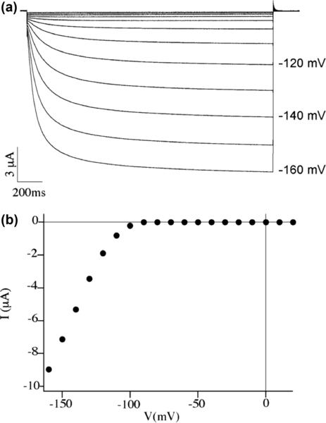
These data confirm the presence of functional Kat1 channels and, given an oocyte diameter estimated at 1 mm, and the conductance of the Kat1 channel being typically 7 pS in symmetrical 100 mM K+, they can be used to assess the density of three active channels per square micrometer.
Endogenous currents (i.e., those due to channels naturally belonging to the cell) have been previously observed and described in Xenopus oocytes, and also in these experiments an inward current, probably carried by Cl2 ions (Dascal, 1987), sometimes disturbed recordings at membrane potential values more negative than −140 mV. To circumvent this problem, we decided to discard batches of oocytes showing large endogenous currents and decided to fix the potential for SFM imaging at −120 mV, a value very close to the half activation potential of Kat1 channels, while limiting possible potential-induced changes in endogenous channels.
It is to be noted that a figure of three per square micrometer for the expression level of functional channels, while remarkable for electrophysiology, appears quite challenging for the kind of experiment we are going to face, that is, finding the channels on the surface of a membrane patch with the scanning tip of an SFM!
5.1.2. Substrate and surface immobilization strategy
In order to succeed in applying an electric field across a supported membrane patch, while imaging it with a scanning force microscope, a mandatory step is to deposit a membrane patch on the surface of a polarizable electrode that shows a roughness value small enough to enable high-resolution (of the order of 1 nanometer) imaging. Our choice is that the substrate plays the role of a working electrode of a three-electrode electrochemical cell (see section 2.5), as we will discuss later on. One of the most convenient materials for making such electrodes is gold, as it can be readily deposited as a thin film on the surface of various supports (glass, SiO2, mica, etc.) routinely used in scanning probe microscopy experiments. Thin (≈ 100 nm) gold films can be typically deposited on those substrates by ion sputtering, e-gun, or thermal evaporation and a number of approaches have been developed to decrease their surface roughness (more precisely, the root-mean-square value of the roughness) down to values enabling high-resolution imaging. Among these techniques and depending on the support to be used, thermal annealing in vacuum, flame annealing, or template stripping from a mica surface can be used (or a combination of the first two approaches). In the case at issue, we made use of the first method, first evaporating a 150 nm-thick Au film on a freshly cleaved mica sheet and then thermally annealing it in vacuum (4 h at 450 °C). The result is a gold surface displaying a typical rms roughness of 0.4 nm.
Another, perhaps more relevant, feature makes the described choice the most attractive by far from an experimentalist’s standpoint. A clean gold surface is indeed readily prone to functionalization by straightforward thiol-based chemistry. Indeed, once a flat enough electrode surface has been achieved, it is necessary to deposit over it a membrane patch that represents the sample to be imaged. It is important to realize that scanning force techniques require the sample be sufficiently immobilized on the substrate to prevent the scanning tip and the subsequent dragging effects from inducing sample movements at the surface. These would completely impair the resolution, making molecular and submolecular recognition unfeasible. The sample immobilization strategy, however, has to avoid a too strong attachment of the biological specimen to the substrate, which would make any gating-induced conformational modifications impossible. In the search for such an optimal balance between the two opposing requirements of firm substrate adhesion and preservation of protein conformational modifications, one can effectively opt for a chemistry that targets primary amines (present typically in surface-exposed lysines and arginines in surface-bound proteins and in some phospholipids; e.g., those characterized by PE headgroups). This approach has the advantage of preserving the freedom of movement of those proteins and/or protein motifs that are buried below the membrane surface, while taking advantage of those primary amines that are exposed off the surface (and that belong to molecules that are not our current experimental target). In practice, the mica-supported gold film was incubated in 1 mg/ml 2-mercaptoethylamine (2-MEA) water solution for 5 min, followed by glutaric dialdheyde (GD) incubation (1% water solution) for 10 min (Facci et al., 2002). This treatment makes the substrate surface adhesive for primary amine moieties (e.g., lysines) and is useful for immobilizing membrane patches by anchoring proteins at the surface.
5.1.3. Strategy for excising membrane patches and adsorbing them onto the electrode surface
After having ascertained that overexpression of the Kat1 channels has taken place in the microinjected oocytes, further processing is needed to produce the membrane patches to be imaged. Generally speaking it is possible to follow well-described procedures in biological chemistry to prepare membrane patch suspensions following various steps that include cell disruption (usually by a French press), followed by ultracentrifugation in sucrose gradient and recovery of the fractions containing the desired membranes. Such an approach, albeit quite standardized and able to provide a reasonable amount of membrane patches, suffers one main trouble, which is the indeterminacy of patch orientation once adsorbed onto the functionalized gold substrate. There is, indeed, virtually no way to predict whether the deposited patch is in an inside-out or outside-out configuration, in electrophysiologist’s terminology; the only possible approach to reveal patch orientation is to use labeled antibodies specific for some markers known to be present only in the inner (outer) side of the membrane.
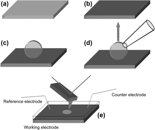
A more straightforward, albeit a bit tricky, solution is that of manipulating a single oocyte at a time, sitting it on the functionalized surface in such a way as to be sure that the membrane patches that one eventually gets at the surface are all in the inside-out configuration. To achieve this goal, the macroscopic size of these oocytes helps. Indeed, after some further dissection steps (performed with a couple of tweezers under an optical microscope) that end with the removal of the vitelline membrane that wraps each oocyte, leaving the plasma membrane exposed, one is ready to adsorb the cell onto the substrate. By the help of a suction pipette, the oocyte can be sucked and gently put on the functionalized gold surface for typically 5 min; afterwards, the pipette is retracted and the oocyte removed. The oocyte footprint on the functionalized surface, a quite large membrane patch (not always uniform but sometimes showing fringes) is thus excised and attached to the surface. As the oocyte membrane is excised, unfortunately, the cytoplasmic content tends to exit the envelope, rapidly diffusing in the incubation chamber. This fact can cause the drawback of allowing a large amount of cytoplasmic material to adsorb onto the functionalized surface, disturbing further SFM imaging. Therefore, to minimize such a phenomenon, the oocyte has to be rapidly withdrawn and the incubation chamber thoroughly perfused with pure buffer. Figure 5.2 shows the main steps of the described procedure.
5.1.4. Measuring chamber implementation and approach for imparting a transmembrane potential drop
The measuring chamber is indeed a three-electrode electrochemical cell where the role of the working electrode is played by a gold substrate, and where a counter and a reference electrode are also present. These three electrodes are then connected to an external potentiostat capable of driving the potential of the substrate with respect to the solution. In the specific implementation of scanning force microscopy with electrochemical control, since measuring cells are usually quite small, one often prefers to go for a quasi-reference rather then a true reference electrode (e.g., Ag/AgCl, Hg/HgCl, etc.). This is, for example, a Ag wire whose potential against a true reference has to be checked before and after the measurements in the imaging buffer (to account for potential drift due to possible chemical modification of the Ag wire surface that does not behave ideally as a reference electrode). The counter or sacrificial electrode is usually made of platinum. Figure 5.2e shows a schematic view of a possible measuring set-up.
The buffer used in the imaging experiments was chosen, on the basis of electrophysiology experience, to be Barth’s solution, with the following composition in mM: NaCl 88, KCl 1, MgCl2 0.82, Ca(NO3)2 0.33, CaCl2 0.41, NaHCO3 2.4, Tris-HCl 5; pH 7.4. Barth’s solution thus plays the double role of physiological buffer and supporting electrolyte for the electrochemical cell.
The described configuration enables one, in principle, to impart a potential drop between the metal substrate and the bulk of solution, and hence a voltage difference across the two sides of a membrane that is adsorbed onto the electrode surface, facing the solution. This situation is made possible by the value of the Debye length in the imaging solution (some nanometers), which allows a sizable potential drop off the electrode surface be localized across the sample membrane. We chose to operate at substrate potential values (i.e., at potential differences between the two sides of the membrane) indicated by electrophysiological measurements: in particular, +120 mV and −20 mV, corresponding to open and closed channel states, respectively (note that the sign of the potential is opposite here with respect to the usual electrophysiology standard).
5.1.5. Imaging strategy and results
The goal of retrieving information on possible conformational modifications of ion channels induced by gating them with an electric field is here addressed by means of SFM imaging. Indeed, this technique possesses the lateral resolution required for that task (Alessandrini & Facci, 2005). Nonetheless, instrumental resolution is only one of the ingredients needed to guarantee successful imaging. The already discussed substrate and sample roughness, stability, limited contamination by other molecules, etc., are concomitant requirements that have to be met to hope for success.
In the specific case, moreover, the aim is to appreciate tiny differences in ion channel conformation that occur upon functional state change (open/closed). The chosen imaging mode therefore has to be very uninvasive in order to allow for optimal resolution and minimum probe-sample interaction (this last aspect being absolutely needed when investigating soft biological samples). The imaging mode of choice for such a goal is the alternating contact mode (Alessandrini & Facci, 2005). We have chosen a magnetic implementation in order to minimize sample disturbance (Han et al., 1996). Briefly, the cantilever is here coated with a magneto-restrictive material that responds to a magnetic field generated by a proximal coil; contractions and elongations of the magnetic coating coupled to the back of the cantilever make this oscillate at a frequency close to its natural one. As in any alternating contact mode, imaging is achieved by controlling the percentage damping of the pre-set free oscillation amplitude as the probe contacts the sample, and exploiting the voltage applied to the vertical piezoelectric actuator needed to control the probe’s vertical position, in order to build up a 2D topographical map of the scanned sample. Details and critical appraisals of this and other SFM imaging techniques can be found in the abundant literature reviewing SFM bioimaging (see, e.g., Alessandrini & Facci, 2005).
Highlighting by SPM subtle differences in Kat1 conformation as a function of its functional state requires that one operates in a differential way, acquiring topographic images of a given membrane area as a function of substrate potential, hence of the transmembrane potential that is imposed on the sample. Indeed, it is only from the fine comparison between the topographic information retrieved by imaging a given portion of sample at different substrate potential values that it is possible to appreciate differences connected to different conformational states the ion channel can assume. Unfortunately, it is not possible to say a priori if a membrane region contains the right molecule, since one observes just bumps where proteins are located. Therefore, one can get a final answer on the presence of the desired “functional” molecules just if one can outline localized morphological differences upon comparing images acquired at different substrate potentials.
Of course the first rough steps in the zoom-in process down to the molecular level can be taken without the complication of performing differential imaging, since they are aimed just at focusing on a membrane patch putatively suitable to be imaged at higher resolution and at different values of substrate potential.
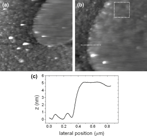
Figure 5.3 shows, as an example, a membrane patch found on a functionalized mica surface. It is interesting to note that the region surrounding the patch, in the shape of a leaf, is decorated with bumps ascribable to soluble proteins coming from the oocyte cytosol, which have been adsorbed onto the reactive mica surface upon membrane excision. Their presence partially influences the membrane patch apparent height, which, nonetheless, appears consistent with what is expected for a cytoplasmic membrane patch.
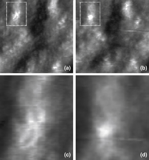
Once a suitable patch has been found, imaging with direct electrochemical control of substrate potential value allows one to seek for zones that have shown morphological modifications in response to changes in the substrate (i.e., transmembrane potential). Operating in the proper potential interval, along with blocking the intrinsic ion currents with proper solution compositions, provides reasonable confidence in the possibility of affecting the state of just Kat1 channels. As already mentioned, maximum overexpression results in about three active channels per square micrometer, a figure that makes finding a shape-changing spot on the sample surface extremely unlikely. As a consequence, one needs to acquire several pairs of images (at potentials corresponding to open and closed states) to sort out those that appear significantly different. In Figure 5.4 an example of positive case is shown. The conformation of the feature that appears as a bump at a potential corresponding to the Kat1 closed state changes drastically on switching the potential to a value typical of the channel open state. Furthermore, the novel apparent feature is somehow shaped like a cross. It is surprising how such a form bears a close resemblance to the tetrameric shape of ion channels of the Shaker superfamily, as revealed by X-ray protein crystallography (Jiang et al., 2003). The particular shape that appears makes one easily believe that these images are really showing a single ion channel having changed its conformation upon voltage gating.
Furthermore, other pieces of evidence corroborate this statement. Indeed, the apparent behavior is consistent with the choice of the particular channel for this experiment. Kat1 is known to be an inward rectifier; as such it is believed to move its voltage-sensitive domains towards the inner part of the plasma membrane upon opening in response to a change in transmembrane voltage. In this experiment, it is the inner side of the membrane that faces off the substrate and that is imaged by AFM, and the results appear to confirm this hypothesis.
It is also worth noticing that part of the channel structure appears to protrude off the membrane surface since this can contribute to shedding light on the molecular mechanisms associated with the event of voltage gating, helping to distinguish among different models for that phenomenon (see section 3.6.1).
Interestingly, the overall size of the shape-changing features well exceeds that of a single tetrameric channel as derived from the X-ray structures of similar molecules. This fact is only partially ascribable to phenomena such as tip–sample convolution that typically affect AFM images (Alessandrini & Facci, 2005). Indeed, the overall apparent size spans about 30 nm, a figure that cannot be accounted for by that kind of artifact. Rather, it appears that a sizable lipid region around the shape-changing features is affected in its structure by the effect of voltage gating. This evidence points to a phenomenon of lipid–protein interaction, most likely of non-specific character. Indeed, an increasing body of experimental evidence suggests that lipid–protein interaction, beyond the involvement of an annular region of specific lipid molecules believed to be crucial for the functioning of certain channels (see, e.g., Lee, 2009; Schmidt et al., 2006), plays a crucial role also at a nonspecific level in the distribution as well as functional behavior of transmembrane proteins (Seeger et al., 2010; Alessandrini & Facci, 2011).
These kinds of experiments, therefore, provide support for the idea that the transmembrane proteins and lipids behave as a single molecular system endowed with given conformational and functional properties. Particularly, voltage gating and ion channel functional behavior is intrinsic to this binary system rather than to the ion channel per se, providing a concrete exemplification of the concept of system biology.
One could argue that it is hard to identify with a high degree of certainty the shape-changing bumps as Kat1 channels and that a positive identification of those molecules is needed to be safe in attributing the apparent voltage-responsive behavior to them. This is indeed an important point that unfortunately is not easy to tackle. One could, for instance, think of using specific antibodies to identify the channels. However, attempts in that direction have so far proved unsuccessful; indeed, it appears quite difficult to take advantage of immunolabeling when one has to deal with ion channels inserted in the membrane, as they are almost completely buried in the bilayer and epitopes that are regularly recognized in other conditions (e.g., Western blot) may be not available in more native situations.
Furthermore, the presence of large macromolecules, such as IgGs, could easily impair the conformational modifications of ion channels conjugated with them, making the experimental attempts described here completely vain.
Whereas inducing conformational modifications in voltage-sensitive ion channels by means of an external electric field can be considered, after all, not a big novelty, changing conformation and altering the affinity of antibodies for their corresponding antigens by a similar means is instead much more unexpected. That is what the next sections are about.
5.2. Direct electrical control of antibody conformation and affinity
A further, relevant framework where electrical control of biomolecular conformation and function can be important is that of biological molecules that per se are neither redox nor electric field responsive. With such a definition we refer to biomolecules whose functionality is usually not described in terms of an interaction with electric fields. Of course, this does not mean they cannot be affected, to a variable extent, by the action of such fields. Indeed, one has always to keep in mind that proteins are, generally speaking, zwitterionic macromolecules and that the charge state of their amino acid residues plays a major role in determining both their conformation and function (Branden & Tooze, 1999).
Our aim here is to show the potential of electrical control over biological entities and reactions and, for such a goal, a further illuminating example to devise strategies to implement control over the functionality of molecules such as antibodies that well represent biological constituents whose function is extremely important from both a physiological and a technological standpoint. Indeed, they mediate the immunological response and are widely used in many technological contexts for revealing and quantifying the presence of various antigens; furthermore, they represent the key molecular ingredient of any immunosensor, irrespective of the transduction mechanism chosen, imparting biochemical specificity to transduction elements (Campbell, 1991).
The implementation of direct electrical control of the functionality of antibodies can pave the way to a number of applications, which may include smart biosurfaces such as bio-adhesive surfaces “on demand”, biomolecular-based memories, switchable immunosensing areas, etc. However, its implementation poses apparently unsolvable problems and requires unconventional approaches and solutions. That is why, in the literature, few attempts have been reported so far with this aim; definitely, the most relevant is that of U. Sivan’s group, which reported the implementation of electrical control over an antibody–antigen reaction (Brod et al., 2008). In that work, the antibody–antigen interaction was monitored with the electrochemical surface plasmon resonance (SPR) technique. The antigen was immobilized on the working electrode while the antibody was injected in solution. After binding, application of a bias more negative than −0.5 V versus the Ag/AgCl reference electrode caused rapid detachment of the antibody molecules from the antigens. Removal of the applied voltage restored the antigen ability to bind the antibody molecules. The mechanism underlying the reported phenomenon was traced back to deprotonation of positively charged amino acids, particularly lysine, by hydroxyl ions generated at the electrode/solution interface. In spite of its interest, however, the reported approach relies on surface immobilization of antigens and on subsequent antibody capture/stripping. As such, it appears of limited technological interest for immunosensor application, where one seeks typically the presence and quantification of antigens in solution. Nevertheless, this work sets the scene for further development of the general concept of making antibody surfaces able to respond to an applied electric field, modulating thus their affinity for the corresponding antigens.
To move further on towards the aforementioned goal, however, a number of aspects deserve critical attention.
The first one is, of course, the choice of the molecules. There exist various types of antibodies that can have a monomeric (e.g., IgD, IgE, IgG), dimeric (e.g., IgA), or pentameric (e.g., IgM) structure. Surface immobilization strategies have been developed in the literature for all of these classes of antibodies (Caiazzo et al., 2009). A general enough possibility appears to be that of focusing on IgG-type antibodies, as the monomeric basic constituents of various antibodies and in view of their wide technological use.
In order to implement electrical driving of antibody–antigen reaction at surfaces, one has to rely on (i) proper surface biofunctionalization and (ii) direct electrochemistry. With these two basic ingredients, it is possible to drive electrically the conformation of surface immobilized antibodies, achieving, as a direct consequence, a modulation of their binding affinity for the corresponding specific antigens. To achieve such a goal, however, it is necessary to immobilize IgG-type molecules in a unique orientation in such a way that specific recognition sites are exposed to the solution, and to find the conditions to affect the IgG conformation with an electric field generated in solution by an electrically polarized metal substrate on which antibodies have to be immobilized.
5.2.1. The supramolecular construct
After the choice of the antibody type, a second, fundamental, aspect to focus on is the molecular immobilization strategy to follow in order to assemble IgGs on a surface. In this case, along with the usual requirements of a firm yet activity-preserving surface functionalization, one has to pay particular attention to antibody orientation. Indeed, this aspect has a major relevance in the specific case; indeed, proper antibody orientation allows for an optimal exposure of the antigen-binding regions on the Fab fragments to the solution containing antigens. Furthermore, a proper molecular orientation is also essential for an electric field to act effectively on the antibody conformation.
In order for an applied electric field to act effectively on surface immobilized molecules in solution, it is convenient to make a metal electrode which also plays the role of the substrate where antibodies are immobilized. This is the approach that we are going to follow to attempt this complex task.
If one chooses gold as the material for the electrode, one is quite naturally biased toward thinking of a thiol-based surface chemistry approach to achieve molecular immobilization. This is of course a plausible possibility but as such it does not provide an easy solution for imparting a specific orientation to the antibodies to be immobilized. Indeed, it is worth noting that a specific molecular orientation can be achieved only if one relies on reaction groups that can follow a single reaction pathway (i.e., reactions that take place between groups present in a single copy on both the molecule to be immobilized and the surface). If more than one copy of these reacting sites is present on the molecular surface, then the final protein orientation becomes unpredictable or not unique. That is the reason for seeking specific conjugation reactions.
When one deals with IgGs, there exists a quite straightforward and effective way of binding them to a surface by means of proteins that have the functional activity of binding Fc fragments with high affinity. These proteins are, for example, bacterial protein A and protein G. Protein A from Staphylococcus aureus possesses five Fc binding sites and can be commercially found in recombinant, mutated form (expressed in E. coli) with some deletion for nonspecific adsorption sites and, most interestingly, with a sequence of six His residues attached to its termini. Especially this last feature can orient one’s choice. Indeed, this very common tag, which is inserted in many recombinant proteins for purification purposes, can help solve the problem of achieving an oriented IgG immobilization.
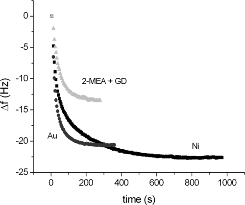
It is well known that His-tag has a high affinity for reagents such as Ni-NTA, which finds typical application in the fabrication of affinity chromatography columns. Less well known is the fact that the tag binds readily onto metal Ni surfaces and also onto Au ones. Figure 5.5 shows quartz crystal microbalance (QCM) adsorption kinetics of protein A on different surfaces, namely a Au surface pretreated so that it targets primary amines (2-mercaptoethylamine + glutaric dialdehyde), a Ni surface and a bare Au surface. As is clearly visible, not only does the His-tagged protein A bind the gold surface very well, but it does it with a much higher saturation level (i.e., surface density) than the more conventional, nonspecific amine-targeting chemistry. These results suggest the use of mutant protein A on gold electrodes as an optimal solution for our immobilization issues. Indeed, besides providing a very high surface density, probably brought about by the higher diffusional degree of freedom that the molecule has on the surface with respect to covalent immobilization, exploiting His-tag for binding protein A to the surface has the remarkable advantage of defining a unique reaction pathway, since that involving the tag is the only effective way the protein can follow to bind to the gold surface. As a consequence, protein A becomes attached to the surface in a unique orientation.
Having settled this first part of the immobilization procedure, the rest is quite straightforward. Exposing the protein A-coated substrate to an IgG solution, antibodies bind readily to the adhesive adlayer. Due to the fact that protein A has, at its surface, an orientation determined by the position of the His-tail and that Fc adsorbs in five specific sites at the protein A surface, the resulting IgG layer appears to be endowed with a preferential orientation. We do not know exactly what that orientation is, but the results that we are going to report in what follows definitely support the idea that IgGs immobilized by the described approach possess a preferential orientation at the surface. Indeed, indirect evidence connected with the surface density of adsorbed IgGs is consistent with the formation of a uniaxially ordered protein layer. Figure 5.6 shows a comparison between the adsorption kinetics of human IgGs bound to a QCM surface with two different treatments. The first one uses an adlayer of protein A immobilized exploiting surface amines (2-mercaptoethylamine + glutaric dialdehyde), whereas the second takes advantage of the His-tag approach.
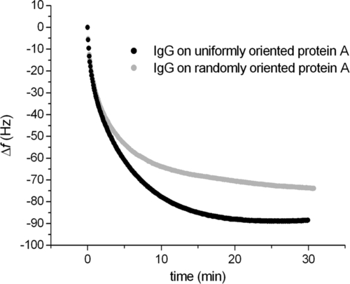
The results reveal a 20% higher IgG coverage in the case of the oriented molecular construct. Interestingly, once the corresponding antigen has been exposed to the antibody layers, the oriented construct appears to capture 30% more antigens than the randomly oriented one. This difference points to an effect of steric hindrance the IgGs of the latter construct experience due to their random orientation on the surface; indeed, they are more prone to have some Fab fragments hidden by neighboring molecules on the surface, at variance with the IgGs of the oriented construct that possess the aforementioned uniaxial order.
5.2.2. Implementing electric control over IgG conformation
An oriented IgG construct is just what one needs to proceed towards the development of a method for gaining technological control of protein conformation. Indeed, a possible solution to that problem lies through the exploitation of protein surface charges and their interaction with an external electric field. In the proposed set-up, an electric field can act on the molecular layer at the surface, being generated by the metal substrate supporting the film that acts as a working electrode of a three-electrode electrochemical cell and is connected to an external potentiostat.
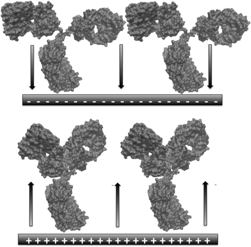
For such a field to act effectively on the molecular layer, some key criteria have to be met. The first one is that the macromolecule at issue has some charged amino acid residues. This is easily achievable by inducing protonation of the primary amine moieties exposed to solution at the IgG surface. The typical IP of IgGs ranges between 6 and 9. Therefore, it is enough to buffer the working solution at pH values below 6 to ensure the presence of positive charges (essentially due to lysines) on the molecules. Another criterion is connected with molecular orientation, since only an overall (at least) uniaxial orientation can enable the layer to respond uniformly to any modulation of the electric field. Such a modulation can involve its intensity and its sign (direction) although it is always perpendicular to the plane of the substrate. Given a uniaxial IgG orientation (with the Fc fragment pointing towards the substrate), a modulation of field direction can have a push-pull effect on the IgGs (mediated essentially by their charged surface residues), probably involving the motion of Fab fragments about their flexible hinges. This is, in a nutshell, the basic idea of the proposed approach. Figure 5.7 shows a simplified scheme of the system as affected by changing the direction of the field.
There is, of course, a further key criterion to meet, that is, to adjust the ionic strength of the operating solution in order to elicit a Debye length long enough to affect the total film thickness (see section 2.2). This is, clearly, a fundamental aspect of the overall enterprise, since the electric potential generated by the substrate has to be effective on the Fab fragments located about 10 nm off the electrode surface. Ionic strength must be set, however, at a high enough value in order for the potentiostatic control to function and for the molecules involved to feel an environment not too different from the physiological one. Proper consideration of all these aspects suggests that 5 mM is the (equivalent) ionic strength to be used in this context, enabling a Debye length of about 10 nm (see section 2.2).
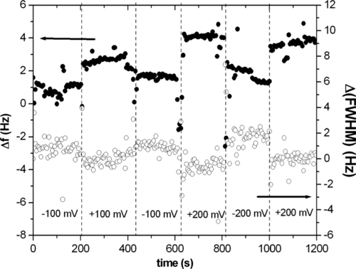
In order to test experimentally the effect on the supramolecular construct of a modulation of the potential value imposed at the working electrode, one can perform electrochemical QCM measurements as a function of the sign and intensity of the applied potential. The aim here is to seek the signature of a change in the conformation of the antibody layer as induced by electric potential modulation. Having immobilized a layer of molecules on one electrode of a QCM, we have measured its response to an electric potential changing in sign and intensity (100–200 mV). Figure 5.8 shows the corresponding data. Variations in both resonance frequency and FWHM (proportional to dissipation) displayed a similar, although opposite in direction, stepwise behavior upon changing electrode potential. These data suggest qualitatively that the layer is responsive to these changes. One can think of potential-induced conformational changes increasing the apparent visco-elastic load measured by QCM since positive charges, hence molecular domains, are attracted towards the electrode surface when it is negatively biased.
These data just confirm that something meaningful happens at the molecular layer upon varying the potential value it senses. In order to deepen our understanding of the phenomena going on in the proposed set-up, another technique can be useful, namely, imaging the molecular layer by electrochemical scanning force microscopy. This is a special application of liquid scanning force microscopy where a potentiostat drives the potential value of the substrate while the microscope records the sample topography as in a conventional SFM experiment. The rationale of these measurements is to image a surface hosting the oriented molecular construct in a differential fashion, that is, at two different values of substrate potential, to seek topographical differences ascribable to IgG conformational variations induced by the applied potential. Of course, since here one deals with scanning force microscopy imaging, the substrate has to be prepared with special care as to its roughness, in order to elicit the imaging of small details. Therefore, we have used mica sheets and the template stripping method (Alessandrini et al., 2008) to grow 100-nm-thick Au films with atomically flat terraces. Then, the orienting treatment described in the previous section has been applied and imaging in tapping mode at different values of substrate potential has been performed on selected surface areas.
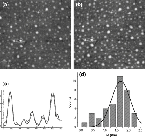
It is indeed hard to detect tiny height changes (of the order of 1 nm) performing repeated surface scans of the same area. Nonetheless, an analysis of the cross-section profiles on the acquired pairs of images clearly reveals differences in the height of the molecular adsorbates that are compatible with the postulated effect of the different potential values on the molecular conformation of IgGs. Figure 5.9 shows two typical ECSFM images along with the corresponding cross-section analysis and the histogram of the height differences of the two images.
These data are indeed compatible with a potential-induced height variation of the IgGs at the surface as due to the pushing effect of the applied electric field.
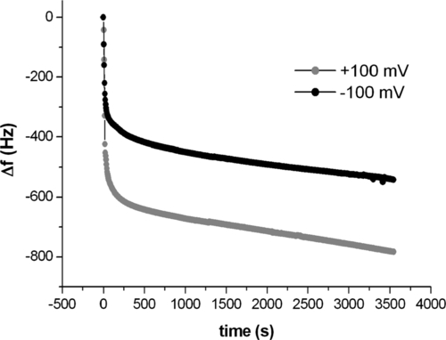
Although images represent in general convincing evidence of a phenomenon, it is difficult to retrieve all the needed information from a single type of measurement when one deals with such tiny, molecular effects. Therefore, it is usually very useful to collect data from different techniques to try to obtain concurrent evidence of the occurrence of a phenomenon. In this context, direct electrochemistry measurements, such as electrochemical impedance spectroscopy (EIS), can provide a valuable input. Indeed, it is possible to perform measurements on the construct at issue keeping the working electrode constituting our substrate at different base potentials, namely −100 and +100 mV, and seeking a difference in the response. Any difference in the response of such a system could be ascribed to conformational variations in the layer. It is interesting to note that, whereas the response of the layer is very different at the two base potentials investigated when the system is kept at pH 5.45, it does not change at all at pH 9. The results can be interpreted with an equivalent circuit that points to a variation in the layer capacitance upon changing potential, corroborating the model of conformational changes in the IgG layer, possibly due to motion of the Fab fragments (even if the possibility of change in overall molecular orientation cannot be completely excluded from these data). Most importantly, the results obtained at pH 9, when IgGs are not charged, confirm the overall mechanism underlying the system as connected to the molecular charge state and consequent response to an applied electric field.
5.2.3. Implementing electric control over IgG functionality
Whereas structural information on the antibody layer is essential to try to understand the exact mechanism that is operating when we vary the potential at the working electrode, we should keep in mind that our final goal is to affect biological reactions, that is, in this specific case, to modulate antibody–antigen affinity. That is why it is essential to provide further evidence of the functionality of the antibody layer as connected to the potential-induced modulation of the IgG conformation.
Towards that further aim, electrochemical quartz crystal microbalance measurements can again turn out to be very useful. Indeed, one can perform adsorption kinetics measurements of specific antigens keeping the antibody layer at different base potentials to seek possible differences in the layer functional properties. Figure 5.10 shows data corresponding to such measurements. One notes that, at variance with a general uniformity in the kinetics aspects of the measurements performed at different base potentials, the saturation level, i.e., the maximum antigen amount captured by the layer, varies markedly between the two situations. This evidence points to modulation of the functional activity of the antibody layer as a function of the substrate potential, that is, as modulated by the different electrically induced IgG conformations. As in a previous case, changing solution pH further confirms the electrical origin of the phenomenon. Furthermore, molecular orientation is also involved in the picture, enabling modulation of the layer functionality. Indeed, the results of antigen binding kinetics measurements performed at two different base potentials on a randomly oriented IgG layer do not show any functional modulation. These data corroborate the overall nature of the picture that now starts to appear quite clearly.
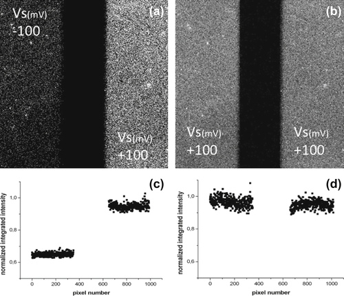
Before drawing final conclusions, it is once more useful to use imaging to try to get a direct insight into the phenomenon of the electrical modulation of the functional activity of oriented antibody layers. It is indeed possible also to rely on fluorescence to further confirm the phenomenon. Briefly, one possibility is to use fluorescently labeled antigens, e.g., FITC-labeled insulin, and a substrate over which two independent Au electrodes have been defined by optical lithography. After having assembled the supramolecular construct on both the electrodes, with the help of a bipotentiostat, it is enough to incubate the antibody-coated electrodes keeping one at a positive (say, +100 mV) and the other at a negative (e.g., −100 mV) potential. After that, one images both electrodes and extracts the integrated fluorescence signal from each electrode. Figure 5.11 shows such images along with the normalized, integrated fluorescence values over the pairs of electrodes. It is clear that the electrode kept at a positive potential has captured about 40% more antigens than that kept at a negative potential value. Whereas the exact amount of antigens captured by a layer based at a positive potential with respect to that kept at a negative potential depends, among the other parameters, on the size of the antigens used, the trend is absolutely general. It is likely that the difference in the capturing ability among layers kept a different potentials can be optimized by finely tuning the antibody surface density (achievable, for example, by co-adsorbing complete IgG molecules and only Fc fragments). At any rate, these results support the concept that antibodies, properly oriented onto an electrode surface and charged thanks to the pH value of the solution, respond to the action of an external electric field modulating their conformation (most likely varying the orientation of their Fab fragments) and as a consequence their affinity for antigens in solution (thanks to the different effects that steric hindrance can have on the attainable conformations).
The reported results extend the control of biological reactions by direct electrochemistry well beyond the framework of the redox reactions, paving the way to further generalization of this approach involving, for example, the modulation of the activity of surface-bound enzymes. Some examples of this kind have started to appear in the literature, albeit the level of molecular control implemented in them is still quite limited.
5.3. Towards direct electrical modulation of enzyme activity
An electric enzyme regulator has recently been proposed (Chao et al., 2012) that takes advantage of a covalent, primary amine-targeting surface chemistry to immobilize the enzyme phenol sulfotransferase onto SiO2 surfaces. In the reactor, the enzyme layer appears to be sandwiched between Pt and Au electrodes. Applying an electric stress to the enzyme layer by polarizing the structure with electric potential values of different sign and intensity results in a modulation of the enzyme activity. Particularly, negative potentials (at the enzyme layer surface) tend to decrease enzyme activity due to its electro-compression towards the substrate, whereas the contrary happens for positive potentials. This effect is traced back by the authors to the charged state of the molecule, which possesses an IP of 5.20–5.66, whereas the working solution is buffered at pH 7. The described situation recalls that described in the case of IgGs, albeit here with a much less defined molecular orientation.
Similarly, the activity of other enzymes (e.g. phospholipase A2) has also been shown to depend upon the action of constant or varying electromagnetic fields to which they are exposed (Maggio, 1999). The difference in the kind of enzymes and in the context in which they operate suggests that the possibility of their electrical modulation is quite large and that it is likely that further examples will appear soon in the literature.
To sum up, the examples reported in this chapter foster the concept of technologically driven smart biosurfaces that can find application in a number of different (nano)technological contexts. Starting from the next chapter, we will enter the charming, largely unexplored, territory of the control of biological reactions in living beings. Then, the concepts developed here will act as a useful starting point towards much more ambitious goals.
..................Content has been hidden....................
You can't read the all page of ebook, please click here login for view all page.