The Generic Access Profile, Chapter 2, offered us a foundation on which we can base our governing profiles. It established generic behaviour for devices during discoverability, connectability and provided common characteristics at the user interface level, through the use of rules and procedures.
In a similar manner, the Service Discovery Application Profile (SDAP) provides us with a foundation on which we can establish user-level clarity with the discovered services of Bluetooth-enabled devices that are in radio range. The SDAP establishes a level of basic functionality, abstracted from the Service Discovery Protocol (SDP). Like the Generic Object Exchange Profile, Chapter 11, it achieves this by establishing a common set of procedural primitives. The service discovery application establishes its high-level functionality from the primitives offered to us by the SDP; there will be more about SDP later on in this chapter. Figure 3-1 offers a representation of a Bluetooth-enabled device in an environment where potentially all the devices surrounding it will respond to a service discovery. The notebook adopts the role of a Local Device, where the Remote Devices, that is, a printer, access point PDA, mobile phone and so on, surrounding it may respond to a service discovery.
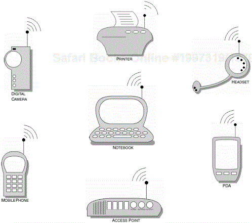
Figure 3-1. The various applications available to a Bluetooth-enabled device. The SDAP provides a model for which we can coordinate the collection of these services into a user-friendly manageable form.
You may recall from the Generic Access Profile, Chapter 2, that an inquiry and device discovery would initially be performed to learn of the devices that are in radio range. Initiating a service discovery could be achieved by selecting the discovered device, where the local device would then perform a service discovery; in Figure 3-2, we illustrate the result of performing a service discovery. The illustration shows only one particular example, where a Bluetooth-enabled device has provided us with a list of services that it is capable of supporting. You will also notice that the SDAP has organised the collection and presentation of the services discovered, also indicating its current connection status. The user can now select the device and choose to connect to the many services on offer, subject to any authentication requirements imposed by the governing profile.
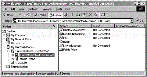
Figure 3-2. A local device has performed a service discovery and has learned of the available services that the remote device has to offer. The service discovery application has coordinated the presentation of the services into a selectable form, where the user can choose the service he or she wishes to use. (Courtesy of TDK Systems Europe.)
In Figure 3-3, we can now see that the user can either double-click [1] or right-click the service icon to begin the process of connecting and using its services.
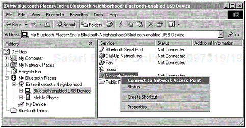
Figure 3-3. A local device has performed a service discovery and has learned of the available services that the remote device has to offer. The user now has the opportunity to connect to the device and make use of its services. (Courtesy of TDK Systems Europe.)
Essentially, SDAP in combination with SDP provides the basic primitive functionality to allow a local device to discover services of remote devices that are in radio range. If we refer back to our earlier illustrations in Figure 3-1 and Figure 3-2, we witness the availability of a remote device responding to the local device offering its available services. In later sections, we will examine in more detail how SDAP uses its underlying protocol to transport the service information to the local device.
The SDAP provides two new roles: a Local Device and a Remote Device. The local device is capable of requesting service information from the remote device to learn of the capabilities that it is able to provide.
In Figure 3-4, we can see the components that make up the SDAP and it is these building blocks that are required to realise a compliant profile. In our introduction, we touched upon the notion that a set of features and procedures exist to help govern the operation of Bluetooth-enabled devices, which support the SDAP. The profile also provides clarification with regards to the dependencies as shown in Figure 3-5 and especially describes how each component realises such functionality. Essentially, what is achieved here is a clear definition of the requirements of the core components that make up the Bluetooth protocol stack; we will discuss this in more detail later on.
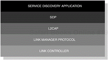
Figure 3-4. The various components that form the building blocks of the SDAP. In similar usage models, the SDP function primitives are exposed at the SDP upper-edge, where applications have a transparent interface to the underlying mode of transport.
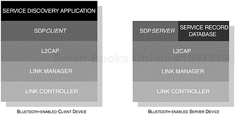
Figure 3-5. The core components of the Bluetooth protocol stack are shown. This illustrates how the components of the SDAP are integrated.
There are no fixed master-slave roles, this allows either device to be free to initiate or terminate a connection, although typically the local device will initiate the primary connection, where inquiry and device discovery procedures have been previously undertaken.
In Table 3-1 clarification is provided with regards to the roles used within the context of this profile. In general, DeviceA represents the initiating party and DeviceB represents the accepting party. The terms are often used interchangeably, when describing specific operations in various contexts and are provided here for reference.
Table 3-1. The list of behavioural characteristics that are typical for this profile.
|
CONFIGURATION |
ROLE |
DESCRIPTION |
|---|---|---|
|
DeviceA |
Local |
The local device initiates the service discovery procedures with the remote device to learn of the services it is capable of supporting. |
|
Client |
In the client-server model, the local device acts as the client who in turn requests from the server the data that is pertinent to its service request. | |
|
Initiator |
This configuration describes the device that instigates the original connection or the device that wishes to initiate communication over an existing link. | |
|
DeviceB |
Remote |
The remote device accepts incoming connections from the local device, which in turn will be provided with the list of services it requests. |
|
Server |
In the client-server model, the remote device is described as the device that serves the client by offering the information it has requested. | |
|
Acceptor |
This configuration describes the process of the device accepting the initiated communication from DeviceA. |
In the following sections, we take an opportunity to explore in greater depth the dependencies that make up this profile. In Figure 3-6, we provide a conceptual illustration representing the dependencies that make up the SDAP; the areas that are shaded are relevant to this profile. As you can see, the profile depends upon the basic functionality offered to us by the Generic Access Profile, Chapter 2 and the components of the Bluetooth protocol stack. We will now discuss in turn the basic requirements of these dependent components and any deviations that may occur from the basic functionality originally offered to us.
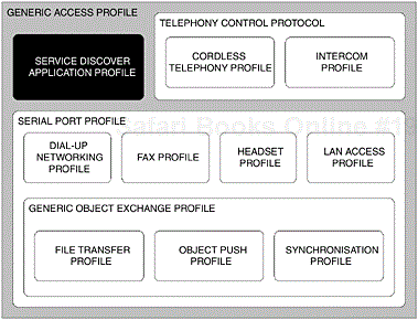
Figure 3-6. The dependent components of the Bluetooth protocol stack that makes up the SDAP. The areas that are shaded are relevant.
We touched upon the fact that SDAP relies upon SDP as its underlying transport. Our focus here is to describe the processes used to obtain service information and to establish how the underlying Bluetooth transport is facilitated in achieving this.
SDP has been designed to sit above the L2CAP component of the Bluetooth protocol stack, as shown in our earlier illustrations. In our first look at understanding this protocol, we will examine its architecture in more detail and then consider specific aspects of integration over L2CAP. In later sections, we will also discuss how SDP Protocol Data Units (PDUs) such as SDP_ServiceSearchRequest, SDP_ServiceSearchResponse and so on are used to realise function primitives.
In Figure 3-5, we illustrated the components that made up our local and remote device protocol stack. In the illustration, you may have noticed that an SDP Client and SDP Server are depicted. In this context, they interact with each other, where the client requests and the server responds; we illustrate this concept in Figure 3-7.

Figure 3-7. In this example, the client (notebook) and the server (printer) use the response-request paradigm to exchange information about the one service being offered.
In the example, the client requests the services from the remote device, where it informs the client that it has one service available. Devices are capable of supporting many services and, as such, we can see in Figure 3-8 that the client requests information about the services that the remote device can support and the SDP server provides a response with multiple services attached.

Figure 3-8. In this example, the client (notebook) and the server (mobile phone) use the response-request paradigm to exchange information about the many services being offered.
The SDP client and the local device communicate with the SDP server of the remote device. Accompanying the SDP server, a Service Discovery Database (SDDB) is used to store information about the services that the remote device is capable of providing. The database is made up of a series of Service Records, which we will discuss in more detail later on. These service records contain detailed information, which enables the local device to know how to use the service on offer. Supplementing this core capability, the owner of the remote device may select how the client should use a service.
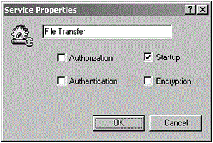
In Figure 3-9, the user is capable of configuring the service to use authentication or encryption. When a local device then uses this particular service, as in the example provided, we can see the user being prompted to select changes for the File Transfer service. The user will have to undertake authentication and encryption procedures before using that particular service.
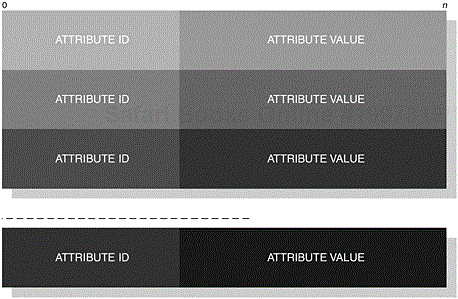
Service Attributes are used to describe the characteristics of a service that should be sufficient for a local device to use. They essentially comprise two units: an AttributeID and an AttributeValue, as we can see in Figure 3-10. The AttributeID is a 16-bit unsigned integer, which is used to uniquely identify the service attribute. In Table 3-2, we provide a list of common service attributes and their associated AttributeID values that are commonly used throughout this book. The AttributeValue is a variable length parameter, where its contents are dependent upon the AttributeID.
The AttributeValue is constructed using data elements. The SDP interprets the AttributeValue to determine its content, where its structure is made up of a header and a data field. In Figure 3-11, we can also see that the Header is further divided into two sections, containing information, which relates to the Type and Size descriptors. The Type descriptor is made up of 5-bits and is placed at the most significant section of the Header byte where it is used to help identify the structure of the following data elements; for example, with an AttributeID of ServiceClassIDList, what follows is a Universally Unique Identifier (UUID). However, with an AttributeID of ServiceName, a Text string would follow. In Table 3-3, we can see the number of available types that can be used.
Table 3-2. The SDP provides a set of unique attributes, which are used to provide sufficient information for a local device to determine what services are available.
|
ATTRIBUTE |
DESCRIPTION |
|---|---|
|
|
This attribute has an ID of |
|
|
This attribute has a unique ID of |
|
|
This attribute has a unique ID of |
|
|
This attribute has a unique ID of |
|
|
This attribute is used to provide user-level description at the user interface, where a choice of languages is available. It has a unique |
|
|
This attribute is used to provide a user-friendly name of the service being provided by the remote device. It has an |
|
|
In supplementing the |
|
|
This attribute is used to describe the manufacturer who, in turn, will be providing the service. It has an |
|
|
This attribute is used to describe the externally connected telephone network that the Cordless Telephony is connected to; it has an |
|
|
This attribute is used to denote whether audio support should be provided for the Dial-up Networking and Fax Profiles; it has an |
|
|
This attribute is used to denote whether a remote volume setting on a headset can be supported; it has an |
In Table 3-4, we identify the Size descriptor, which occupies the remaining 3-bits of the Header byte; this descriptor is contained in the least-significant section. It is used to describe the size of the data represented by the Type descriptor.
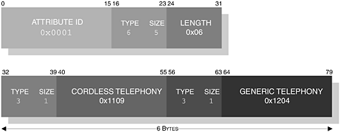
Let us pause for a moment and summarise what has been previously outlined. A service is constructed with a series of ServiceAttributes. These attributes are capable of uniquely identifying to a local device what service is being supported by the remote device. In its construction, a series of data elements are used to describe the format of the ServiceAttribute, where an AttributeID and AttributeValue are used. In Table 3-2, we identified a list of common attributes that are often referred to in this book. The AttributeValue is further used to describe the format contained within the data element. In Figure 3-12, we illustrate the encoding of the ServiceClassIDList for Cordless Telephony.
In the illustration, we can see that the AttributeID contains the ServiceClassIDList reference of 0x0001, see Table 3-2. The AttributeValue is constructed to contain two UUID values, which represent Cordless Telephony (0x1109) and Generic Telephony (0x1204). With this type of encoding, the construction becomes twofold: in the first instance, we describe that a data sequence follows, by using the Type descriptor 6, see Table 3-3.
Secondly, our Size descriptor indicates 5; see Table 3-4, which illustrates that the following 1-byte contains the size of the entire data sequence. In the illustration, we also note that our Length is 6-bytes. The encoding of the remaining data sequence now indicates a Type descriptor of 3, which denotes UUID and the Size descriptor indicates that the next 2-bytes contain the actual UUID value.
With a collection of ServiceAttributes, a Service Record is constructed; this record essentially conveys to a local device all the information it needs to know about using the service. Figure 3-13 provides a conceptual structure of a service record. In the following section, we discuss in some more detail the use of service records and how service browsing is achieved.
In our earlier introduction we provided an illustration, which demonstrated that a device was capable of supporting multiple services, see Figure 3-2. A service record is maintained for each service the device is capable of supporting and, as such, a Service Record Handle is created to uniquely identify a service record.
Table 3-3. The list of available Type descriptors that form the most-significant section of the Header.
|
TYPE |
DESCRIPTION |
|---|---|
|
|
Null. |
|
|
An unsigned integer. |
|
|
A signed 2’s complement integer. |
|
|
A Universally Unique Identifier (UUID). |
|
|
A text string. |
|
|
Boolean ( |
|
|
A sequence of data elements. |
|
|
A data element alternative: a sequence of data elements, where one must be chosen. |
|
|
A Uniform Resource Locator (URL). |
A minimum of two attributes are required to make a service record, these are ServiceRecordHandle and ServiceClassIDList, where the latter attribute must contain at least one UUID; Table 3-5 provides a list of AttributeIDs, which ultimately would identify the service for the Cordless Telephony Profile.
The ServiceRecordHandle is a 32-bit unsigned integer and is stored on the remote device SDP server. You may recall from Figure 3-5 and our earlier discussion on the client-server model where the local device maintains an SDP client and the remote device manages the SDP server. The SDP server communicates with the Service Record Database, as to the available services it can offer the local device.
Table 3-4. The list of available Size descriptors that form the least-significant section of the Header.
|
SIZE |
DESCRIPTION |
|---|---|
|
|
1 Byte (or zero if a Null |
|
|
2 Bytes. |
|
|
4 Bytes. |
|
|
8 Bytes. |
|
|
16 Bytes. |
|
|
This value denotes that the following 1 Byte contains the size. |
|
|
This value denotes that the following 2 Bytes contain the size. |
|
|
This value denotes that the following 4 Bytes contain the size. |
When performing a service discovery of a remote device, the client undertakes a series of procedures to learn of the services it supports. Browsing is used to refer to the mechanism that is employed when you seek an unknown or general service is sought. In our earlier discussion, we provided several AttributeIDsthat are used to construct a service record. A generic AttributeID, which is common to all services is the BrowseGroupList attribute, this has a unique value of 0x0005. As with any AttributeID, the associated AttributeValue can be constructed with a data sequence. In this particular instance, the AttributeValue relates to the group to which the service belongs.
Table 3-5. The list of AttributeIDs that make up a service record for the Cordless Telephony Profile.
|
ATTRIBUTE |
DESCRIPTION |
|---|---|
|
|
With an |
ServiceClassIDList ServiceClass0 ServiceClass1 |
With an |
ProtocolDescriptorList Protocol0 Protocol1 |
With an |
BluetoothProfile DescriptorList Profile0 ParameterFor0 |
With an |
|
|
With a base |
|
|
With an |
With the intent to search for services on a remote device, the local device constructs a Search Pattern, which is a list of UUIDs. UUIDs are 128-bit values, which have been shortened for use within Bluetooth applications. The shortcut has been provided by first establishing a Bluetooth Base UUID, which is shown in Table 3-6.
Table 3-6. The Bluetooth Base UUID that is used as a default reference from which all other UUIDs are generated.
|
BLUETOOTH BASE UUID |
|---|
|
|
The UUIDs that have been presented so far are aliases and take the form of what is referred to as a 16- or 32-bit UUID; in turn, they all should refer to the 128-bit notation. These UUIDs have been assigned and can be referenced in the Bluetooth Special Interest Group, Bluetooth Assigned Numbers, v1.1, February 2001. For a search pattern to be successful, it needs to be converted to the 128-bit notation, since all searches will be compared at this range. In Table 3-7, we illustrate the arithmetic operation, which performs the conversion from the 16-bit and 32-bit representation into the full 128-bit notation.
Earlier, we touched upon the fact that a set of function primitives is established to realise true functionality within SDAP. In an attempt to expand our understanding of the companionship of the profile and protocol, we will begin by looking more closely at how the Service Discovery Protocol is used. Furthermore, we will explore the underlying mechanism that is exposed to the Service Discovery Application Profile, which in turn provides it with its primitive functionality.
A set of abstractions is used to provide and forms the basis of the core functionality. The SDP employs the use of a series of PDUs. The local device retrieves specific information with regards to the services available on the remote device, using a combination request and response PDU.
The profile relies upon the protocol for the request and response functionality and, in turn, the protocol then further relies on its underlying transport mechanism to facilitate the transport of the PDUs. To achieve this, the protocol makes use of the services provided by L2CAP, where the connection-orientated transport service is made available. The L2CAP component then subsequently uses an Asynchronus-Connectionless (ACL) link to take the PDUs over the air.
In Table 3-8, the combination request and response PDUs that are available within the protocol are illustrated, although you must bear in mind that the illustration provided does not represent an Application Programming Interface (API). Higher-level functionality or a user application would be employed to extract the relevant data from the PDU, where it would interpret the data and formulate the appropriate response. As such, the local and remote devices, which form the communicating parties, each have their own user application to fulfill their respective functional expectations.
Table 3-7. The arithmetic operation, which is used to covert 16-bit and 32-bit UUIDs to the full 128-bit UUID notation.
|
16-Bit AND 32-Bit TO 128-Bit CONVERSION |
|---|
|
|
Table 3-8. The SDP provides simple request-response PDU paradigm used to retrieve information about the specific services of the remote device.
|
FUNCTION |
DESCRIPTION |
|---|---|
|
|
This response PDU is generated, when the SDP receives a request from the client, when it is incorrectly formatted. |
|
|
This combination request-response PDU is used to instigate a search request using the |
|
|
This combination request-response PDU retrieves specific attribute record information from the server, whereas the previous function retrieved all records that match a particular pattern. A range of parameters is provided in the response, where the |
|
|
Finally, this combination request-response PDU encompasses both the functionality of the |
The SDAP is conceptually positioned above the SDP in a user application on the local device, where it is referred to as the SrvDscApp (or Service Discovery Application). Here, it not only relies upon the protocol, it also embraces the use of a client (SDP client) and a management component; elsewhere in this book, this is commonly referred to as a Management Entity
[2] (ME) for consistency. This component forms the basis on which discovery effort is coordinated, providing instructions for some certain operational modes, such as an inquiry or a paging state. The placement and existence of such a module remains implementation-specific. The remote device coordinates requests from the local device with the use of an SDP server and a service record database, which contains service records relevant to the services available.
In essence, the profile allows you as a developer to realise an API, which utilises the inherent protocol. The SDAP is therefore capable of providing this primitive functionality through the use of the SDP. We discuss the application perspective in more detail in Section 3.3.1.2, SDP in the Service Discovery Application Profile.
This itself is the minimum functionality you would expect from the profile, but should not be seen as an inadequacy, since it does not restrict the growth of other implementation-specific APIs. Coincidentally, in Part III, The New Profiles, the ESDP: An Overview, Chapter 18, we discuss the Extended Service Discovery Profile (ESDP) and how it fits within the SDAP context.
The SDP PDUs are used to instruct the server to undertake browsing procedures and to retrieve service record information about its services. As we previously discussed, the client and server operate a request and response paradigm. The SDAP will construct PDUs containing information relating to the AttributeID and AttributeValues in turn instructing the server to carry out its operation. Each PDU has a unique value, which are shown in Table 3-9.
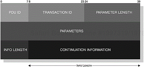
In Figure 3-14, we illustrate the structure of a SDP PDU; this is applicable to all SDP_ErrorResponse PDUs. However, a Continuation State parameter is added to the remaining PDUs, since an SDP PDU response may be too large to fit into a single response. The server indicates that the client has only received a partial response and the client re-issues the original request with the ContinuationState copied into the new request to retrieve the remainder of the response.
The ContinuationState is of a variable length and is constructed of two further parameters. The Info Length parameter is the first byte used to indicate the size of Continuation Information parameter. When the request is re-issued, the server is first informed of the size of the ContinuationInformation, which instructs it where it had segmented the original response. The InfoLength parameter is set to zero to indicate that the response was completed in one transaction. We can see the structure of the PDU with the ContinuationState parameter as shown in Figure 3-15. You will also notice from our illustrations that a TransactionID parameter and a ParameterLength are also shown. The former parameter is a 16-bit unsigned integer used to identify the request PDU and is selected at random by the client, but it must be different to any other pending request. The TransactionID in the response PDU will be used to match the associated request. The ParameterLength is a 16-bit unsigned integer and is used to accurately describe the entire length of the PDU.
Table 3-9. The list of values that are used to identify the PDU.
|
VALUE |
PDU |
|---|---|
|
|
Reserved. |
|
|
|
|
|
|
|
|
|
|
|
|
|
|
|
|
|
|
|
|
|
During normal operation the client and server exchange information with a request-response operation. However, if an incorrectly formatted request is sent to the server, it will respond with SDP_ErrorResponse. In Table 3-10, we can see the PDU format with its set of parameters.
The ErrorInfo parameter is implementation-specific, whereas the ErrorCode parameter attempts to provide a reason for the failure. In Table 3-11, we can see the list of errors that are used to describe the reason for failure.
Earlier, we touched upon the fact that a search pattern is created to seek services from the remote device. In the SDP_ServiceSearchRequest PDU, the ServiceSearchPattern contains the data element sequence, which will contain a series of UUIDs. In Table 3-12, we identify the request-response PDUs with their set of parameters. The MaximumServiceRecordCount parameter is a 16-bit unsigned integer that specifies the maximum number of services that should be returned. The ContinuationState parameter is constructed of a 1-byte InfoLength parameter used to describe the size of the ContinuationInformation parameter. The latter parameter here would contain n-bytes of information, which relates to a previous uncompleted response. The ContinuationInformation parameter must not be greater than the maximum of 16-bytes. If no partial response has been provided then the first part of the ContinuationState parameter is set to zero, indicating that there was no previous partial response.
The SDP_ServiceSearchResponse is returned containing a list of ServiceRecordHandles, which have been selected based upon the search pattern criteria. The TotalServicesRecordCount is an unsigned integer, which stores the number of services obtained and should never exceed the MaximumServiceRecordCount; the TotalServicesRecordCount will be zero if none were found. The ContinuationState parameter is constructed of a 1-byte InfoLength parameter used to describe the size of the ContinuationInformation parameter, where a maximum size of 16-bytes is possible. If no partial response has been provided, then the first part of the ContinuationState parameter is set to zero, indicating that the response was completed.
Table 3-10. The SDP_ErrorResponse that is used to indicate an error in the request packet.
|
RESPONSE |
PARAMETERS |
|---|---|
|
|
|
Table 3-11. A range of ErrorCodes that is used to identify why a request failed.
|
ERROR |
DESCRIPTION |
|---|---|
|
|
Reserved. |
|
|
Unsupported SDP Version. |
|
|
Invalid |
|
|
Invalid Request Syntax. |
|
|
Invalid PDU Size. |
|
|
Invalid |
|
|
Insufficient Resources. |
This combination of request-response PDUs will allow a specific service to be retrieved from the server. In the SDP_ServiceAttributeRequest PDU, the ServiceRecordHandle, which is a 32-bit unsigned integer, contains the identity of the service to be retrieved; this handle was previously retrieved using the SDP_ServiceSearchRequest PDU. In Table 3-13, we identify the request-response PDUs with their set of parameters. The MaximumAttributeByteCount parameter is a 16-bit unsigned integer that specifies the maximum number of bytes that should be returned. The AttributeIDList contains a data element sequence, where the actual size varies; this is used to identify the attributes that are being sought from the remote server. The ContinuationState parameter is constructed of a 1-byte InfoLength parameter used to describe the size of the ContinuationInformation parameter. The latter parameter here would contain n-bytes of information, which relate to a previous uncompleted response. The ContinuationInformation parameter must not be greater than the maximum of 16-bytes. If no partial response has been provided, then the first part of the ContinuationState parameter is set to zero, indicating that there was no previous partial response.
Table 3-12. The request-response combination used to retrieve a specific search pattern containing a list of UUIDs.
|
REQUEST |
PARAMETERS |
|---|---|
|
|
|
|
RESPONSE |
PARAMETERS |
|---|---|
|
|
|
Table 3-13. The request-response combination used to retrieve a specific search pattern containing a list of UUIDs.
|
REQUEST |
PARAMETERS |
|---|---|
|
|
|
|
RESPONSE |
PARAMETERS |
|---|---|
|
|
|
This particular request-response PDU minimises the amount of PDU traffic over the air-interface, since a specific service record is being retrieved. The response is generated when a service record being requested has been found. The AttributeListByteCount holds the total number of bytes that are contained in the AttributeList parameter. The AttributeListByteCount must never be larger than the MaximumAttributeByteCount parameter. The AttributeList contains a data element sequence of the service that was retrieved by the server. The ContinuationState parameter is constructed of a 1-byte InfoLength parameter used to describe the size of the ContinuationInformation parameter, where a maximum size of 16-bytes is possible. If no partial response has been provided, then the first part of the ContinuationState parameter is set to zero, indicating that the response was completed.
This combination of request-response PDUs combines the functionality offered to us in our previous PDUs. In the SDP_ServiceSearchAttributeRequest PDU, the ServiceSearchPattern contains the data element sequence, which will contain a series of UUIDs. In Table 3-14 we identify the request-response PDUs with their set of parameters. The MaximumAttributeByteCount parameter is a 16-bit unsigned integer that specifies the maximum number of bytes that should be returned. The AttributeIDList contains a data element sequence, where the actual size varies; this is used to identify the attributes that are being sought from the remote server. The ContinuationState parameter is constructed of a 1-byte InfoLength parameter used to describe the size of the ContinuationInformation parameter. The latter parameter here would contain n-bytes of information, which relates to a previous uncompleted response. The ContinuationInformation parameter must not be greater than the maximum of 16-bytes. If no partial response has been provided, then the first part of the ContinuationState parameter is set to zero, indicating that there was no previous partial response.
Table 3-14. The request-response combination that is used to retrieve a specific search pattern containing a list of UUIDs and returns a list of AttributeIDs and AttributeValues.
|
REQUEST |
PARAMETERS |
|---|---|
|
|
|
|
RESPONSE |
PARAMETERS |
|---|---|
|
|
|
The response is generated when a service record being requested has been found. The AttributeListByteCount holds the total number of bytes that are contained in the AttributeList parameter. The AttributeListByteCount must never be larger than the MaximumAttributeByteCount parameter. The AttributeLists contains a data element sequence of the service that was retrieved by the server. The ContinuationState parameter is constructed of a 1-byte InfoLength parameter used to describe the size of the ContinuationInformation parameter, where a maximum size of 16-bytes is possible. If no partial response has been provided, then the first part of the ContinuationState parameter is set to zero, indicating that the response was completed.
In Section 3.3.1.1, The Service Discovery Protocol we learned about how request and response messages are created to provide us with basic functionality. We then went on to discuss how we could create an API and expose it to our application, where genuine functionality could be realised. We also learned that the SDP component would parse incoming request and response packets, where an action can be decided based upon the encoded data. In this section, we now consider the objectives of SDP in the profile and its expectations. In establishing our operations and its primitive functionality, the profile discusses mandatory features that it expects from the protocol and provides guidance with regards to how a service discovery application might achieve these objectives.
In our earlier discussion, we touched upon the application convention that is used with an application embodying service discovery capabilities. We discussed that an application residing on a client would be named SrvDscApp (Service Discovery Application). The SrvDscApp uses the SDP client to instigate request and to subsequently receive response PDUs to learn of the services available. The remote device must support an SDP server, where responses are sent back to the local device. These dependencies are illustrated in Table 3-15.
The SrvDscApp would undertake a series of actions to retrieve the services from the remote device. A remote device may be in one of three states when the local device commences its search; these are described in Table 3-16. These states are not restricted to a one-to-one communication link. A device discovery may return the availability of numerous devices that are in radio range and it is assumed that the ME, as previously discussed, is capable of instructing the lower-layers to enter inquiry and page scan substates. The SrvDscApp may undertake service retrieval from one device at a time, where it first establishes a connection to collect the service information. When all service information has been retrieved, the SrvDscApp will terminate its current connection and establish a new connection with the next device, although if the device is currently connected then the SrvDscApp may choose not to terminate its connection.
In Figure 3-16, we illustrate the possible sequence of events that occur between the local and remote device. The illustration does not show any authentication processes, since the user of the remote device determines the provision of authentication and pairing, and therefore its use is optional.
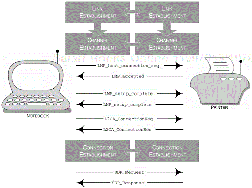
Figure 3-16. The sequence of events that occur when an SDP session is established. Authentication may be required between the local and remote device, but it is not shown here.
You may recall from our earlier discussion in Section 3.3.1.1.1, The Client-Server Model, that the user of a remote device can choose to mandate the authentication and encryption requirements. The inquiry and pairing procedure may not necessarily be undertaken since the device may be trusted or already connected.
The idiosyncrasies of a SrvDscApp remain implementation-specific, but its core capabilities to retrieve service information are mandated. We now take an opportunity to reflect on function primitives, which may in turn be a suitable framework for a developer to start looking at an implementation of the SDAP. In describing these primitives, it is assumed that these will have access to the PDUs and its underlying functionality, which we previously discussed. In Table 3-17, we outline the mandatory (M) and excluded (X) PDUs that are required to implement such primitives. Our discussion refers to the operation of a local and remote device and how interaction is achieved between them.
Table 3-15. As a minimum, the local device must support the use of a client application and the remote device must support the use of a server.
|
FEATURE |
LOCAL |
REMOTE |
|---|---|---|
|
SDP Client |
M |
O |
|
SDP Server |
O |
M |
Table 3-16. The remote device will be in one of these states. The SrvDscApp must be capable of managing the appropriate sequence of events to retrieve service information from the remote device.
|
STATE |
DESCRIPTION |
|---|---|
|
Unknown |
The remote device has not been discovered and the user would need to perform an inquiry and device discovery procedures to learn of the availability of the device in radio range. |
|
Trusted |
A device in this state would indicate that a previous connection had occurred, but it is no longer connected. As a result of this previous connection the devices maintain a trusted relationship, that is both devices have paired. |
|
Connected |
The local and remote devices have an active connection. |
In Table 3-18, we illustrate suggested, although not necessarily compulsory, since implementations will differ from manufacturer to manufacturer, function primitives, which in turn encompass a complete sequence to retrieve a service. An actual function content is constructed at the discretion of the developer. You may wish to incorporate activities such as inquiry and page scan substates, where you can at least obtain the availability of devices within radio range. Alternatively, you may wish to keep it simple and restrict to simply acquiring service information. It is important to understand what is discussed here is not cast in stone and as a developer any API that you create is at your discretion.
Table 3-17. A SrvDscApp must have access to the core capabilities of the SDP.
|
PDU |
LOCAL |
REMOTE |
|---|---|---|
|
|
X |
M |
|
|
M |
X |
|
|
X |
M |
|
|
M |
X |
|
|
X |
M |
|
|
M |
X |
|
|
X |
M |
The L2CAP layer provides transparency for the upper layers of the stack from the layers typically found within the host controller. L2CAP payloads are passed to the Host Controller Interface [3] (HCI), which is then subsequently passed onto the Link Manager Protocol (LMP). The range of upper layers, which include RFCOMM, SDP and Telephony Control Protocol Specification (TCS) all make use of the capabilities offered to us by L2CAP. Its primary role is to provide protocol multiplexing, allowing numerous simultaneous connections to be made, and also providing the ability for segmentation and reassembly. This refers to the ability to manage large payloads in the application, which may need to be fragmented into smaller payloads for the lower-layers to manage; these are then transmitted over the air-interface. Finally, the L2CAP layer exchanges Quality of Service (QoS) information, ensuring that sufficient resources are available and that both Bluetooth devices are attaining the best service.
In Table 3-19, we summarise the broad capabilities that are expected from L2CAP and in the table you will notice features are marked with M (Mandatory), O (Optional), X (Excluded), C (Conditional) and N/A (Not Applicable), these determine what is expected from the L2CAP layer.
In Table 3-19, we have identified that Connection-orientated Channels are mandatory, whereas Connectionless Channels are excluded; this type of channel is aimed at broadcasting, where all devices may be targeted. L2CAP uses PDUs to transport connection, signalling and configuration options, which will be discussed in a moment. The higher-layers of the Bluetooth protocol stack will instigate a connection with L2CAP using the L2CA_ConnectReq request packet, where the corresponding result is contained within the L2CA_ConnectRsp response packet. An L2CA_ConnectRspNeg negative response packet is used to denote a response, where the connection with the remote device was unsuccessful. Since our profile resides above L2CAP and employs its services, we are only concerned with the upper protocol layer of L2CAP. This higher functionality is offered to us through a series of L2CAP events and is denoted through the prefix L2CA_; see Table 3-20.
Table 3-18. An SrvDscApp must have access to the core capabilities of the SDP.
|
PRIMITIVE |
DESCRIPTION |
|---|---|
|
|
This primitive may be used to first establish a connection with a remote device where at least a communications pathway exists over the air-interface for service information to be exchanged. |
|
|
Conversely, this function would be used to terminate a connection with the remote device once sufficient service information has been obtained. |
|
|
This type of primitive may be used to encompass multiple searches on many remote devices. An |
|
|
Again, using the |
|
|
A search can be performed on the basis of a Class of Device (CoD) identification. This primitive encompasses some form of filtering where specific devices based on the CoD are filtered. |
When creating an L2CAP connection between two devices, a Protocol/Service Multiplexor (PSM) value is used to denote the higher-layer protocol that is using the connection; Table 3-21 identifies these values and the corresponding protocol they represent. The value of 0x0001 (SDP) is used for this profile.
Table 3-19. The illustration shows specific procedures that this profile depends upon to realise its compliant implementation.
|
PROCEDURE |
LOCAL |
REMOTE |
|---|---|---|
|
Connection-Orientated Channel |
M |
M |
|
Connectionless Channel |
X |
X |
|
Connection Establishment |
M |
C |
|
Configuration |
M |
M |
|
Connection Termination |
M |
C |
|
Echo |
M |
M |
|
Command Rejection |
M |
M |
|
Maximum Transmission Unit |
M |
M |
|
Flush Timeout |
M |
M |
|
Quality of Service |
O |
O |
When establishing communication with a remote device, a signalling channel is created and reserved for use during connection, disconnection and configuration of subsequent L2CAP connections. A channel is used to describe the communication and data flow that exists between L2CAP entities and Table 3-22 illustrates the range of Channel Identifies (CIDs) that are used to identify the channel type. As we can see in Table 3-19, Connection Establishment and Termination is mandatory in the local device, although the remote device may be capable of initiating and terminating a connection to the local device. The L2CA_DisconnectReq request packet is used to terminate the connection with the remote device and a L2CA_DisconnectRsp response packet is used to ascertain the result of the termination; although all disconnection requests must be completed successfully. The support of Configuration is shown as mandatory and we will discuss these specific options in more detail in the following section. Finally, Echo and Command Rejection are both mandatory for a compliant SDAP.
Table 3-20. The range of prototypes used to illustrate how L2CAP is architected and how interaction between higher- and lower-layers is achieved. For this discussion, our concern here is with the higher-layer.
|
PROTOTYPE |
DESCRIPTION |
|---|---|
|
|
This prefix prototype is used to denote the higher-layer interaction, typically used by RFCOMM, SDP and TCS. |
|
|
This prefix is used to denote peer-to-peer signalling interaction of L2CAP entities. |
|
|
Finally, this prefix denotes lower-layer interaction, where L2CAP interfaces with the LMP layer. |
In establishing a connection with the remote device, the channel is subject to configuration and the higher-layer prototype L2CA_ ConfigReq request packet is used to carry configuration requests. Its associated response is contained within the L2CA_ConfigRsp packet; an L2CA_ConfigRspNeg packet is used to denote a negative response during configuration, where for example the suggested Maximum Transmission Unit (MTU) is too large. In Table 3-19, we have identified that the MTU and Flush Timeout parameters are mandatory, whereas the QoS is optional.
The default MTU setting for the signalling channel is 48 bytes, whereas other channels may be capable of transferring larger payloads; essentially the MTU determines the size of payloads that are capable of being exchanged between two devices. During configuration, the local device will inform the remote device that it is potentially capable of accepting larger payloads. If the remote device is unwilling to accept a larger MTU, then the local device is informed with the response contained within the L2CA_ConfigRspNeg packet.
Table 3-22. The CIDs used to represent the logical channel.
|
CID |
DESCRIPTION |
|---|---|
|
|
Null |
|
|
Signalling Channel |
|
|
Connectionless Reception Channel |
|
|
Reserved |
|
|
Dynamically Allocated |
When L2CA_ request and response packets are being exchanged, the Flush Timeout parameter is used to determine how long the local device is prepared to continue to transmit an L2CAP fragment before it gives up; the packet is subsequently flushed or in other words discarded. The suggested Flush Timeout value is sent during the L2CA_ ConfigReq request packet. However, if no value is set, then the default value is used. The SDAP uses the default value of 0xFFFF.
As we have already mentioned, the QoS configuration is optional, but if it is used during an L2CA_ConfigReq request, then the best effort service is established as a default; the available services that are supported for an L2CAP channel are shown in Table 3-23. However, if the QoS service is set at Guaranteed, then parameters such as Token Rate, Token Bucket, Peak Bandwidth, Latency and Delay Variation, are used to determine an acceptable guaranteed service, where the L2CA_ConnectRspNeg, will indicate that these values are unacceptable. These parameters are then subject to further negotiation.
The Link Manager (LM) layer sits between the HCI and the Link Controller (LC), although on a hostless system the LM will have direct interaction with L2CAP. It accepts commands from HCI and translates them into operations for the LC, where ACL and Synchronous Connection-Orientated (SCO) links are created and established. It is during this stage of ACL and SCO establishment that a master-slave switch would be performed as governed by the requirements of this profile. The LM is also responsible for placing the device into a low-power mode, which includes hold, sniff and park.
In providing general error management, devices that operate mandatory procedures during interoperability, must either acknowledge their support or provide a suitable reason informing the initiator why the procedure failed. The LMP_Detach PDU is used to inform the device of the error that occurred; typically the reason unsupported LMP feature (0x1A) is reported, see Appendix A.
Table 3-23. The range of service definitions that are used during QoS.
|
SERVICE |
DESCRIPTION |
|---|---|
|
No Traffic |
This indicates that the channel will not be sending any traffic and, as such, any parameters can be ignored. |
|
Best Effort |
This default value attempts to achieve a minimum service with the remote device, where no guarantees are offered. |
|
Guaranteed |
With this service definition, we indicate that we wish to achieve the maximum bandwidth permitted, of course subject to the nature of a wireless environment. |
In our following discussion, we take an opportunity to explore the dependencies that make up the SDAP, where we provide a narrative of the capabilities that are expected at this level. Table 3-24 identifies the capabilities that are required from this layer and in the following subsections we discuss the specific procedures in more detail.
Table 3-24 summarises the broad capabilities that are expected from the LM and in the table you will notice procedures are marked with M (Mandatory), O (Optional), X (Excluded), C (Conditional) and N/A (Not Applicable); this will determine what is expected from the procedures at the LM. What has been included in the table is a set of deviations that the profile requires, which is above the common set of procedures expected at LM.
Authentication and encryption in this profile is not necessarily mandated. However, if the remote device imposes such restrictions on the local device, it is expected that both devices will provide support. If a device does not support such a procedure, then the error behaviour as previously outlined must be adhered.
Authentication is used when DeviceA and DeviceB share a common link key or initialisation key, which is typically obtained during the pairing process. You may remember from our earlier chapter that the pairing process requires a user to enter a Bluetooth Passkey.
The authentication process encompasses LMP Authentication procedures, but all LMP Pairing procedures must have been performed prior to this event. As for the LMP Authentication procedure, this is primarily based on a challenge-response scheme. Here, the verifier or DeviceA sends the LMP_au_rand command, containing a random number to the claimant or DeviceB; the random number forms the challenge aspect of this scheme. The response, forming the final part of this scheme, is sent to the verifier using the LMP_sres command, which contains the result of the operation. If the operation is what the verifier expected, then it considers the claimant as authenticated.
The LMP Pairing procedure occurs when there is no link key and, as such, if an LMP_au_rand is sent to the claimant it will respond with LMP_not_accepted offering the reason as key missing (0x06), see Appendix A. If a key has been previously associated with the claimant, then the claimant proceeds to calculate the response and provides the verifier with a response through LMP_sres. However, if the calculated response is incorrect the verifier can terminate the connection with the command LMP_detach, offering the reason as authentication failure (0x05), see Appendix A; Table 3-25 summarises the LMP commands used during authentication.
The process of encryption commences when at least one device has authenticated. DeviceA (or client) takes the initiative and needs to determine whether to include encryption for point-to-point or broadcast communication. If DeviceB (or server) is agreeable to the parameters offered by the master, the master proceeds to communicate further detailed information about the encryption parameters.
The actual process is invoked when the two parties agree to use encryption and then L2CAP communication terminates, where the master then sends the LMP_encryption_mode_req command. If this is acceptable to the slave, it too terminates all L2CAP communication and responds with the LMP_accepted command. The next step in this process actually determines the size of the encryption key and it is the master that sends the LMP_encryption_key_size_req command, where it offers an initial recommendation of the key size to use. The slave, in turn, then offers its own recommendation, where it informs the master what it thinks it might be capable of. Both master and slave will repeat this process until they reach an agreement, however, if neither party reaches a decision then the LMP_not_accepted command is sent, offering the reason as unsupported parameter value (0x20), see Appendix A.
Upon accepting the key size the LMP_accepted command is issued and the encryption procedure then takes place by issuing the LMP_start_encryption_req command with a random number, which is used to calculate the encryption key. Table 3-26 summarises the available commands for the encryption process.
The LC layer is the lowest layer depicted in the dependencies of this profile and is responsible for a large number of core capabilities. It manages air-to-interface transactions and determines the fundamental timing of ACL and SCO data packet transmission and reception, as well as coordinating effort at its upper-edge with the LM. It also encompasses the management of the various packet types and the various inquiries and paging procedures that are available. In turn, the following subsections provide clarity with regards to the capabilities that are a requirement at the LC level for the SDAP. In our understanding of the dependencies, we begin by examining in more detail the supported capabilities and a small discussion is offered for each, where support is deemed as mandatory. If you are a developer providing profile-specific applications, then it is unlikely that you will engage in a large part of this component, although in some audio-related applications direct access may be required, where a faster transport mechanism can be supported. Nevertheless, many manufacturers have architected an audio-specific API for intelligible access to this component.
Table 3-26. The range of LMP PDUs available for encryption.
|
PDU |
PARAMETER |
|---|---|
|
|
|
|
|
|
|
|
|
|
|
None |
Table 3-27 summarises the broad capabilities that are expected from the LC and in the table you will notice features are marked appropriately; this will determine what is expected from the features at the LC.
An inquiry procedure is used to learn of the other devices in radio range, where the Bluetooth Device Address (BD_ADDR) and clock offsets are obtained; it is DeviceA that will enter an inquiry substate to perform this procedure. A device that wishes to be discovered (DeviceB) will enter an inquiry scan substate, where the device will respond with an inquiry response. In this state, DeviceB is waiting to receive an Inquiry Access Code (IAC). From an application perspective, these modes of operation are discussed in more detail in the Generic Access Profile, Chapter 2. It is here that specific rules are determined with regards to the behaviour of such devices and how long these devices can operate in such modes. When devices have been discovered, this information is passed over to the SDAP, which manages the specific attributes that make up that device. What is being established here, as a dependency, is that the Bluetooth protocol stack must encompass and support such behavioural procedures for this profile to be considered compliant.
The inquiry substate and inquiry scan substate procedures are the initial methods used to learn of other devices in radio range; to this extent, the device has discovered sufficient information to gain a connection with the remote device. This is achieved when DeviceA has the intent to create a connection with DeviceB; DeviceA is now placed into a paging substate, where it will periodically transmit the Device Access Code (DAC). The DAC is used to target the device directly and the clock offset is used to gain an idea of the clock cycle of DeviceB. These parameters were originally obtained during our inquiry procedures. If DeviceB wishes to be connected, then it will enter a page scan substate and will respond accordingly to DeviceA. An inquiry procedure may be avoided if the BD_ADDR is already known, although a connection may take a little longer if the clock offset is not known.
Inter-piconet capabilities describe the process that allows the master to manage multiple connections from slave devices. During a connection, other users may temporarily witness degradation in the service that is being provided; however, the master must be capable of accepting new participants in the piconet.
There are numerous packet types available and Table 3-28 identifies the most often used packets for profile support. There are also a number of common packet types that are used for general purpose transport; for example, the ID packet is used for inquiry procedures and a POLL packet would be sent by DeviceA to determine if a slave is active on a channel.
Table 3-28. The summary of packet types that are required for the LC to enable a compliant SDAP.
|
PACKET TYPE |
LOCAL |
REMOTE |
|---|---|---|
|
|
M |
M |
|
|
M |
M |
|
|
M |
M |
|
|
M |
M |
|
|
M |
M |
|
|
M |
M |
|
|
X |
X |
|
|
X |
X |
|
|
X |
X |
|
|
X |
X |
The DM1 packet type is used to transmit control data over any connection, but may be used to transport a genuine payload. HV1, HV2 and HV3 are various SCO packet types to carry audio-specific data, where a DV packet can combine ACL and SCO specific data; their support in this profile is reflected in Table 3-28. Various ACL packet types are also available, in fact seven types including the DM1 type are attributed to carrying user-specific data; these include DH1, DM3, DH3, DM5, DH5 and AUX1; similarly, Table 3-28 summarises their support in this profile.
Service Discovery is used when learning about the services or capabilities that remote devices are capable of supporting.
It is assumed that an inquiry and a device discovery procedure have already been performed.
Performing a device discovery allows you to learn of the devices in radio range, whereas a service discovery provides you with a list of services that can be supported by that device.
A local and remote device is used to represent the partying devices: a local device initiates a service discovery and a remote device responds.
A client and server model is used to represent the operating model when requesting and responding to PDUs.
A series of PDUs exist to illustrate the operations required to perform a specific function.
The
SrvDscAppis used to realise functionality at the user-interface level.The
SrvDscApputilises an API, which in turn performs the necessary operations, which may provide device discovery procedures as well as service discovery procedures.SDAP relies on the SDP as its underlying mode of transport.
SDP is structured to provide you with response-request scheme, working with a client-server model.
Unique
AttributeIDsandAttributeValuesare used to describe to a local device what the services are.A user may make use of services by initiate a connection with the device.
[1] The double-click and right-click operations refer to a mouse that is connected to your local device (in this example, a PC or notebook computer running a Microsoft Windows operating system) and where both operations trigger the two methods of enabling. It is noted that this operation may vary from device to device and as such the number of buttons may vary on a mouse and indeed no mouse may be connected. The example just draws your attention to how it may be possible and acknowledges that implementations may differ.
[2] The SDAP actually refers to the equivalent entity as a Bluetooth Module Controller, but essentially the ME supports the same mechanisms.
[3] L2CAP payloads are passed directly onto LMP when implemented on a hostless system.

