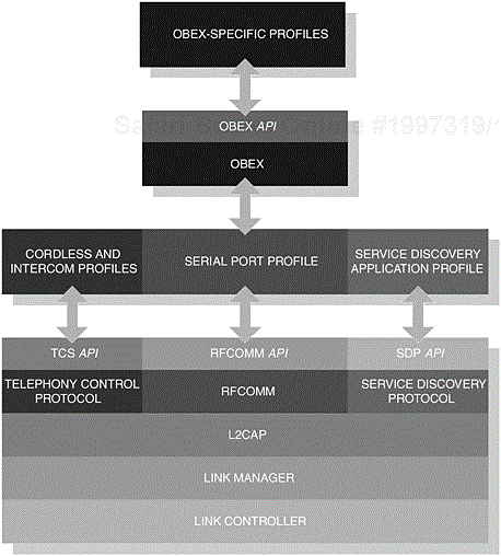
The Generic Access Profile establishes a level of basic functionality, abstracted from the core protocol components. In Figure 2-1, we illustrate the components that make up the core protocol, where at the upper-edge of the illustrated components, implementers would establish function primitives in the form of an Application Programming Interface (API). This exposed API would then allow implementers to realise their profile requirements. In turn, this ultimately would allow them to construct Bluetooth applications.
Furthermore, providing this basic set of rules and procedures it then becomes sufficient to realise that the behaviour of such devices is governed with simple rules that relate to their connectivity, discoverability and common characteristics at the user interface level, with some additional emphasis provided for security. These rules and procedures are used to establish commonality between products, which will ultimately achieve a cohesive user experience.
All foundation profiles [1] have their basis in the Generic Access Profile. That said, this profile outlines a set of comprehensive requirements that may be used in the governing profile; [2] for instance, if a feature in the Generic Access Profile is described as optional, it may be determined that a feature should be mandatory in the governing profile. This chapter aims to build upon your understanding of this fundamental profile and allow you to strengthen your knowledge of the features which make up both it and its governing profiles.
Table 2-1. The list of requirements (and symbols) used to denote the inclusion or exclusion of specific features within a profile.
|
REQUIREMENT |
SYMBOL |
DESCRIPTION |
|---|---|---|
|
Mandatory |
M |
A feature that must be supported by a profile. |
|
Optional |
O |
A feature that may be used by a profile. |
|
Conditional |
C |
A feature that may be used by a profile, if other capabilities are provided. |
|
Excluded |
X |
A feature that, although possibly supported by the device, will not be used by the profile. |
|
Not Applicable |
N/A |
A feature that is not applicable for the operation of that profile. |
In providing a comprehensive understanding of profile implementation, it is important to emphasise certain key features. These features are often denoted with degrees of adoption and are described as mandatory, optional, conditional, excluded and not applicable. Table 2-1 condenses the categorisation of these key features and offers clarification to their meaning, as they will be referred to during the course of this book.
In our introduction, we touched upon the notion that a set of rules and procedures exist to help govern the operation of Bluetooth-enabled devices, which support the Generic Access Profile. The profile further provides clarification with regards to the dependencies as shown in our earlier illustration and especially describes how each component realises such functionality. Essentially, what is achieved here is a clear definition of the requirements on the core components that make up the Bluetooth protocol stack; we will discuss this in more detail later on.
In general, DeviceA represents the initiating party and DeviceB represents the accepting party. The terms are often used interchangeably, when describing specific operations in various contexts and are provided here for reference. The Generic Access Profile describes procedures for two devices that wish to discover and connect to the services on offer, although participating devices are not necessarily restricted to this two-way communication. In Figure 2-2, we demonstrate that the central notebook is capable of connecting to many devices that are in radio range, where these devices can offer a variety of services. In the example shown, the PDA may then independently wish to connect to the printer.
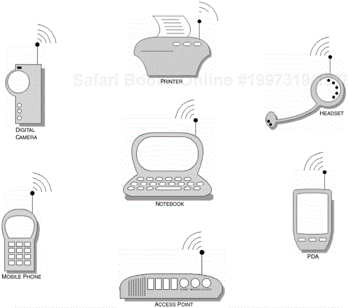
Figure 2-2. The Generic Access Profile provides a comprehensive set of procedures for DeviceA (the Notebook in this example) that wishes to connect to and make use of the services provided by DeviceB (let us say the PDA). However, the PDA may independently initiate a connection to another Bluetooth-enabled device.
The operations of DeviceA and DeviceB are used to facilitate the general procedures as previously outlined, although we have touched upon deviations that may occur in other profiles. DeviceB may operate several profiles (or services) and, as such, the implementation of DeviceB may differ to accommodate these variations. In simple terms, the Generic Access Profile provides the foundation upon which other profiles can be based.
This profile does not mandate the operation of a master-slave switch; this is specifically addressed by the needs of the governing profile. It is DeviceB that usually determines whether or not it has a need to become master and in one such example, DeviceB may already be the master of an existing piconet and therefore may insist that it remains master of that relationship. Alternatively, DeviceA may decide that a role-switch is not permitted and choose to remain master as well. In either case, the device may decide not to continue and fail the link establishment altogether.
It is advisable that the role-switch is performed immediately after the physical-link is established, where the connection request parameters [3] determine whether or not a role-switch can be performed. It is the governing profile that will ultimately determine whether or not master-slave switching is mandatory. In another example, a master-slave switch is mandatory if the LAN Access Profile is configured for multi-user mode; see the LAN Access Profile, Chapter 10 for more information.
The Generic Access Profile provides generic capabilities for the user who, in turn, will be capable of connecting to any device and determining the services available to him or her. This generic capability should be inherent within different manufacturers’ products and as such interoperate regardless. This seamless and transparent operation makes Bluetooth technology the success it is today.
What allows this operation to be successful is the common set of rules and procedures that govern the generic behaviour of Bluetooth-enabled devices. These can also be extended to naming conventions used at the user interface level, where the user wishes to discover available devices in radio range. The user will inevitably come across several parameters that are used to uniquely identify a device and its services.
The following sections provide the common naming conventions that the user will come across at the user interface level. In the later sections, discoverability, connectability and pairing procedures are also explored.
As we have already discussed, the user will come across several names, which are used to identify the device. On discovering the capabilities of a device, the user will learn of its name and its class, as well as its unique Bluetooth address. In Figure 2-3 and Figure 2-4, the parameters are disclosed to the inquiring device when the user performs a device discovery operation.
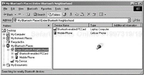
Figure 2-3. The screen shot shows the results of a device discovery procedure where the list of expected parameters are named according to the general rules provided within the Generic Access Profile. (Courtesy of TDK Systems Europe.)
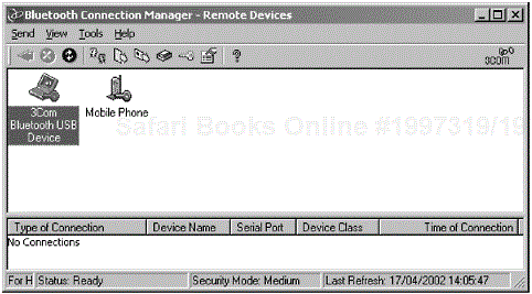
Figure 2-4. The screen shot shows the results of a device discovery procedure where the list of expected parameters are named according to the general rules provided within the Generic Access Profile (the 3Com Bluetooth Connection Manager has discovered another 3Com device and a mobile phone is also shown).
The Bluetooth Device Address parameter uniquely identifies the Bluetooth device and is often referred to as BD_ADDR at the baseband level. For every Bluetooth device, there will be a unique address assigned to it. It is based upon the Media Access Control (MAC) address notation, which is already used to uniquely identify a computer that is connected to a Local Area Network (LAN). The BD_ADDR is retrieved during an inquiry or device discovery procedure and is described as the Bluetooth Device Address at the user interface level as previously shown in Figure 2-3 and Figure 2-4.
We show in Table 2-2, the HCI_Read_BD_ADDR command, which is used to request the device address from the local device and the Command_Complete event is used to acknowledge completion of the request. In the return parameters, the success of the command is determined by the Status parameter and the BD_ADDR parameter will contain the address of the local device.
At the baseband level, BD_ADDR is represented as 48-bits; however, the user will see a 12 byte hexadecimal notation, where this representation may be subsectioned for an easy read. The presentation of this number will have the most-significant byte (MSB) and least-significant byte (LSB) shown from left-to-right.
Table 2-2. The command and event used in combination to retrieve the local Bluetooth Address.
|
COMMAND |
PARAMETERS |
|---|---|
|
|
|
|
EVENT |
PARAMETERS |
|---|---|
|
|
|
When performing a device discovery procedure, a user-friendly name is also retrieved and presented to the user, as we have seen in Figure 2-3 and Figure 2-4. The unique Bluetooth address is not a sufficient description to determine what the device is capable of and, as such, a user-friendly name can be provided to aid identification. On the user interface level, this parameter is referred to as the Bluetooth Device Name.
Table 2-3. The command and events used in combination to retrieve the user-friendly name from the remote device.
|
COMMAND |
PARAMETERS |
|---|---|
|
|
|
|
EVENT |
PARAMETERS |
|---|---|
|
|
|
|
|
|
Table 2-4. The PDUs available within LMP that are responsible for retrieving the Bluetooth Device Name.
|
PDU |
PARAMETER |
|---|---|
|
|
|
|
|
|
We show in Table 2-3, the HCI_Remote_Name_Request command, which is used to request the user-friendly name from the remote device and the Remote_Name_ Complete event is used to acknowledge completion of the request.
The following Link Manager Protocol (LMP) Protocol Data Units (PDUs), in Table 2-4, detail the LMP commands that are used to retrieve the user-friendly description. The Bluetooth Device Name can be up to 248-bytes in length, although not all bytes have to be used. There may be restrictions in what can be displayed at the user interface level and generally only the first 20 bytes can be shown. What can be displayed will typically be determined by the restriction of the user interface of the device itself and thus may be implementation-specific. Such environments may include an embedded cordless handset or a mobile phone, which has a limited display.
The LMP_name_req command is sent indicating which fragment to expect. The response is then received with the LMP_name_res command, where the parameters determine the length of the name and the fragment, since the Bluetooth Device Name can be fragmented over several DM1
[4] packets.
The Name Discovery procedure obtains the Bluetooth Device Name, as we have previously discussed, where the provision of this feature is optional. The retrieval process at the user interface level is described as the Bluetooth Device Name Discovery and is usually performed during a limited or general device discovery procedure. This process encompasses the idle mode procedures that are typical for the Generic Access Profile.
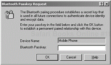
Before two devices can have a relationship, there has to be an element of trust. The Bluetooth Passkey is used to build that trusted relationship prior to performing authentication. In Figure 2-5, the user is prompted to enter a Bluetooth Passkey to commence the process of establishing the trusted relationship.
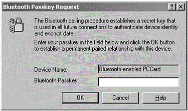
Figure 2-5. The screen shot shows a user being prompted to enter a Bluetooth Passkey before two devices can have a trusted relationship. (Courtesy of TDK Systems Europe.)
We show in Table 2-5, the HCI_PIN_Code_Request_Reply command, which is used to respond to a PIN_Code_Request event, where it specifies the passkey to use for the current connection. This is typically generated during an HCI_Create_Connection or through the HCI_Authentication_Requested commands.
The Bluetooth Passkey is often referred to as the Personal Identification Number (PIN) and is described as PINUI for user interface representation and PINBB for baseband level representation. However, the user will only see the term Bluetooth Passkey when connecting to DeviceB, as previously shown in Figure 2-5.
The passkey or PIN is then used in the pairing procedure and is further used to generate a common link key; there will be more about this later (see Section 2.5.4, Pairing). In Figure 2-6, we illustrate the user being prompted when an invalid passkey has been entered; in some instances, the user may be prompted again to enter a valid passkey.
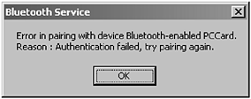
Figure 2-6. The screen shot shows a user being prompted when the incorrect Bluetooth Passkey was entered. (Courtesy of TDK Systems Europe.)
Consideration should also be given to devices that do not have a user interface but must still utilise a Bluetooth Passkey. In these instances, it is possible that this passkey can be stored within the device itself and should only take the form of decimal digits. Remember, the inquiring device (DeviceA) should also be capable of supporting the entry of decimal digits. A Bluetooth headset may require the user to authenticate with the device and, as such, enter a valid passkey. In such instances, manufacturers have either supplied the user with a Bluetooth Passkey card or have made it part of the unique serial number.
Table 2-5. The command and event that are used in combination to retrieve the local Bluetooth Address.
|
COMMAND |
PARAMETERS |
|---|---|
|
|
|
|
EVENT |
PARAMETERS |
|---|---|
|
|
|
Whether the passkey is stored or entered in by the user a transformation has to occur from PINUI to PINBB to allow the generation of the link key for the pairing procedure, as we previously touched upon. This is achieved through mapping alphanumeric characters, which are entered on the user interface level to the UTF-8 [5] format for the appropriate baseband representation. The user interface level is also capable of managing a range of alphanumeric characters, which include decimal and alphabetic. The PINBB is 128-bits in length or 16-bytes, although not all bytes have to be used and, as such, the PINUI may be less than the maximum 16-bytes available.
When performing a device discovery, a Bluetooth Device Class is retrieved to specifically identify the type of device and the type of services that it is capable of supporting. Within an FHS [6] packet, a Class of Device (CoD) field is used to provide sufficient information with regard to the service, major and minor class groupings; Figure 2-7 shows the placement of the CoD field within the FHS packet.

Figure 2-7. The structure of the FHS packet used only for reference to illustrate the position of the CoD structure.
The CoD field is further sectioned into 3-bytes (or 24-bits) as shown in Figure 2-8. In the illustration, we can uniquely identify the Service, Major and Minor device class grouping, where in the following sections we will look more closely at the parameters which make up this field.

Figure 2-8. The structure of the class of device, illustrating the Minor Device, Major Device and Service Class fields and their respective lengths.
Table 2-6. The Service Class categorisation.
|
SERVICE CLASS | |||||||||||
|---|---|---|---|---|---|---|---|---|---|---|---|
|
23 |
22 |
21 |
20 |
19 |
18 |
17 |
16 |
15 |
14 |
13 |
Bit # of CoD |
|
0 |
0 |
0 |
0 |
0 |
0 |
0 |
0 |
0 |
0 |
1 |
Limited Discovery |
|
0 |
0 |
0 |
0 |
0 |
0 |
0 |
0 |
0 |
1 |
0 |
Reserved |
|
0 |
0 |
0 |
0 |
0 |
0 |
0 |
0 |
1 |
0 |
0 |
Reserved |
|
0 |
0 |
0 |
0 |
0 |
0 |
0 |
1 |
0 |
0 |
0 |
Positioning (Localisation) |
|
0 |
0 |
0 |
0 |
0 |
0 |
1 |
0 |
0 |
0 |
0 |
Networking |
|
0 |
0 |
0 |
0 |
0 |
1 |
0 |
0 |
0 |
0 |
0 |
Rendering (Printing, Speakers) |
|
0 |
0 |
0 |
0 |
1 |
0 |
0 |
0 |
0 |
0 |
0 |
Capture (Scanner, Microphone) |
|
0 |
0 |
0 |
1 |
0 |
0 |
0 |
0 |
0 |
0 |
0 |
Object Transfer |
|
0 |
0 |
1 |
0 |
0 |
0 |
0 |
0 |
0 |
0 |
0 |
Audio |
|
0 |
1 |
0 |
0 |
0 |
0 |
0 |
0 |
0 |
0 |
0 |
Telephony |
|
1 |
0 |
0 |
0 |
0 |
0 |
0 |
0 |
0 |
0 |
0 |
Information |
Table 2-7. The range of Major Device Classes available to Bluetooth-enabled devices.
|
MAJOR DEVICE CLASS | |||||
|---|---|---|---|---|---|
|
12 |
11 |
10 |
9 |
8 |
Bit # of CoD |
|
0 |
0 |
0 |
0 |
0 |
Miscellaneous |
|
0 |
0 |
0 |
0 |
1 |
Computer: Desktops, Laptops and PDAs |
|
0 |
0 |
0 |
1 |
0 |
Phone: Mobiles, Cordless, Payphones and Modems |
|
0 |
0 |
0 |
1 |
1 |
LAN and Network Access Point |
|
0 |
0 |
1 |
0 |
0 |
Audio: Headsets, Speakers and Stereos |
|
0 |
0 |
1 |
0 |
1 |
Peripherals: Mouse, Joysticks and Keyboards |
|
0 |
0 |
1 |
1 |
0 |
Imaging: Printing, Scanner, Camera and Displays |
|
1 |
1 |
1 |
1 |
1 |
Unclassified, device code has not been assigned |
The Service class is the highest form of categorising a Bluetooth device. In Table 2-6, we show the service class definitions that are currently available.
Table 2-7 identifies the Major class grouping. This represents another level of granularity for the definition of a Bluetooth device.
Taking the granularity to the next level, the following tables identify further groupings when the Major Device class is not suitable, although the correct interpretation is given for the Major Device class context. In Table 2-8, we illustrate the available groupings for the Computer Major Class.
Table 2-8. The Minor Device Class set for the Major Device Class grouping for Computer.
|
MINOR DEVICE CLASS | ||||||
|---|---|---|---|---|---|---|
|
7 |
6 |
5 |
4 |
3 |
2 |
Bit # of CoD |
|
0 |
0 |
0 |
0 |
0 |
0 |
Unclassified, device code has not been assigned |
|
0 |
0 |
0 |
0 |
0 |
1 |
Desktop Workstation |
|
0 |
0 |
0 |
0 |
1 |
0 |
Server-class Computer |
|
0 |
0 |
0 |
0 |
1 |
1 |
Notebook |
|
0 |
0 |
0 |
1 |
0 |
0 |
Handheld PDA or PC |
|
0 |
0 |
0 |
1 |
0 |
1 |
Palm-sized PDA or PC |
|
0 |
0 |
0 |
1 |
1 |
0 |
Wearable Computer (watch sized) |
Table 2-9. The Minor Device Class set for the Major Device Class grouping for Phone.
|
MINOR DEVICE CLASS | ||||||
|---|---|---|---|---|---|---|
|
7 |
6 |
5 |
4 |
3 |
2 |
Bit # of CoD |
|
0 |
0 |
0 |
0 |
0 |
0 |
Unclassified, device code has not been assigned |
|
0 |
0 |
0 |
0 |
0 |
1 |
Mobile Phone |
|
0 |
0 |
0 |
0 |
1 |
0 |
Cordless |
|
0 |
0 |
0 |
0 |
1 |
1 |
Smart Phone |
|
0 |
0 |
0 |
1 |
0 |
0 |
Wired Modem or Voice Gateway |
|
0 |
0 |
0 |
1 |
0 |
1 |
Common ISDN Access |
In Table 2-9, we illustrate the available groupings for the Phone Major Class. In Table 2-10, we illustrate the available groupings for the Access Point Major Class. Table 2-10 shows the loading on the access point, which occupies bits 5, 6 and 7 of the minor device field; the lower 3-bits of the field are reserved.
In Table 2-11, we illustrate the available groupings for the Audio/Video Major Class. In Table 2-12, we illustrate the available groupings for the Peripheral Major Class. The field is sectioned, where the upper two bits, 7 and 6 are used to specify the Keyboard, Mouse and a Combo device. The lower four bits can then be used in combination for multifunctional devices; this is shown in Table 2-13.
Table 2-10. The 3-bit upper area of the minor device class that depicts the utilisation of an Access Point.
|
MINOR DEVICE CLASS | |||
|---|---|---|---|
|
7 |
6 |
5 |
Bit # of CoD |
|
0 |
0 |
0 |
Fully Available |
|
0 |
0 |
1 |
1 to 17% Utilised |
|
0 |
1 |
0 |
17 to 33% Utilised |
|
0 |
1 |
1 |
33 to 50% Utilised |
|
1 |
0 |
0 |
50 to 67% Utilised |
|
1 |
0 |
1 |
67 to 83% Utilised |
|
1 |
1 |
0 |
83 to 99% Utilised |
|
1 |
1 |
1 |
No Service Available |
Table 2-11. The Minor Device Class set for the Major Device Class grouping for Audio/Video.
|
MINOR DEVICE CLASS | ||||||
|---|---|---|---|---|---|---|
|
7 |
6 |
5 |
4 |
3 |
2 |
Bit # of CoD |
|
0 |
0 |
0 |
0 |
0 |
0 |
Unclassified, device code has not been assigned |
|
0 |
0 |
0 |
0 |
0 |
1 |
Device conforms to the Headset Profile |
|
0 |
0 |
0 |
0 |
1 |
0 |
Hands-free |
|
0 |
0 |
0 |
0 |
1 |
1 |
Reserved |
|
0 |
0 |
0 |
1 |
0 |
0 |
Microphone |
|
0 |
0 |
0 |
1 |
0 |
1 |
Loud Speaker |
|
0 |
0 |
0 |
1 |
1 |
0 |
Head Phones |
|
0 |
0 |
0 |
1 |
1 |
1 |
Portable Audio |
|
0 |
0 |
1 |
0 |
0 |
0 |
Car Audio |
|
0 |
0 |
1 |
0 |
0 |
1 |
Set-top Box |
|
0 |
0 |
1 |
0 |
1 |
0 |
HiFi Audio Device |
|
0 |
0 |
1 |
0 |
1 |
1 |
VCR |
|
0 |
0 |
1 |
1 |
0 |
0 |
Video Camera |
|
0 |
0 |
1 |
1 |
0 |
1 |
Camcorder |
|
0 |
0 |
1 |
1 |
1 |
0 |
Video Monitor |
|
0 |
0 |
1 |
1 |
1 |
1 |
Video Display and Loud Speaker |
|
0 |
1 |
0 |
0 |
0 |
0 |
Video Conferencing |
|
0 |
1 |
0 |
0 |
0 |
1 |
Reserved |
|
0 |
1 |
0 |
0 |
1 |
0 |
Gaming/Toy |
In our final look at the class grouping, Table 2-14 illustrates the available groupings for the Imaging Major Class. The field is also sectioned, where the upper four bits, 7, 6, 5 and 4 are used to specify the Display, Camera, Scanner and a Printer device.
The lower two bits can then be used in combination for multifunctional devices; this is shown in Table 2-15.
The following commands, as shown in Table 2-16 and Table 2-17, are used in combination to identify and set the device categorisation as we previously discussed. The HCI_Read_Class_of_Device parameter is used to retrieve the capabilities of the local device, which in turn informs other devices of its capabilities. A Command_Complete event is used to acknowledge a successful operation.
Table 2-12. The 2-bit upper area of the minor device class that depicts the categorisation of a peripheral.
|
MINOR DEVICE CLASS | ||
|---|---|---|
|
7 |
6 |
Bit # of CoD |
|
0 |
1 |
Keyboard |
|
1 |
0 |
Pointing Device |
|
1 |
1 |
Combo Keyboard/Pointing Device |
Table 2-13. The 4-bit lower area of the minor device class that depicts the categorisation of a multifunctional peripheral device.
|
MINOR DEVICE CLASS | ||||
|---|---|---|---|---|
|
5 |
4 |
3 |
2 |
Bit # of CoD |
|
0 |
0 |
0 |
0 |
Uncategorised |
|
0 |
0 |
0 |
1 |
Joystick |
|
0 |
0 |
1 |
0 |
Gamepad |
|
0 |
0 |
1 |
1 |
Remote Control |
|
0 |
1 |
0 |
0 |
Sensing Device |
Table 2-14. The 4-bit upper area of the minor device class that depicts the categorisation of an imaging device.
|
MINOR DEVICE CLASS | ||||
|---|---|---|---|---|
|
7 |
6 |
5 |
4 |
Bit # of CoD |
|
0 |
0 |
0 |
1 |
Display |
|
0 |
0 |
1 |
0 |
Camera |
|
0 |
1 |
0 |
0 |
Scanner |
|
1 |
0 |
0 |
0 |
Pinter |
Table 2-15. The 2-bit lower area of the minor device class that depicts the categorisation of a multifunctional imaging device.
|
MINOR DEVICE CLASS | ||
|---|---|---|
|
3 |
2 |
Bit # of CoD |
|
0 |
0 |
Uncategorised |
|
x |
x |
Reserved |
The HCI_Write_Class_of_Device parameter is used to set the capabilities for the local device, which in turn informs other devices of its capabilities. A Command_Complete event is used to acknowledge a successful operation.
The following sections now discuss modes of operation for discoverability, connectability, pairing and security. Each mode of operation determines the behaviour of a device and, as such, the governing profile may determine if these features are mandatory or optional.
For some discoverability procedures, such as time available for discovery or inquiry scan substates, a time constraint may be applied to that operation. Table 2-18 provides a list of timers available to the Generic Access Profile. The notation TGAP(xxx) is used to identify the timer for a specific operation, where xxx identifies the timer reference within the table; the values provided are only recommendations.
Table 2-16. The command and event used in combination to retrieve the Bluetooth Device Class.
|
COMMAND |
PARAMETERS |
|---|---|
|
|
|
|
EVENT |
PARAMETERS |
|---|---|
|
|
|
Table 2-17. The command and event used in combination to set the Bluetooth Device Class.
|
COMMAND |
PARAMETERS |
|---|---|
|
|
|
|
EVENT |
PARAMETERS |
|---|---|
|
|
|
The mode of discoverability determines whether or not a device can be discovered for use with any other device. There are several modes of operation for discoverability and these will be discussed in the following sections. A device will only operate in one mode at any one time and can be discoverable if set in the limited or general discoverability mode. Once made discoverable, a device will only be available for at least TGAP(103).
The initial procedure required for discovering the availability of a device is an inquiry and, as such, if a device is configured for non-discoverability it will not respond to an inquiry, although, other baseband activities may take precedence where the device is unable to respond. The term silent device is used to describe a device that fails to respond as per the reasons previously outlined. In Figure 2-9 and Figure 2-10, we can see two different implementations performing an inquiry, where a list of devices that have been found are then shown.
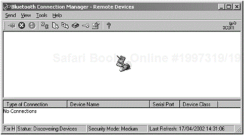
Figure 2-9. The screen shot shows DeviceA performing a device discovery, where the initial procedure initiated is a discovery of devices in radio range (the 3Com Bluetooth Connection Manager is shown performing a device discovery).

Figure 2-10. The screen shot shows DeviceA performing a device discovery, where the initial procedure initiated is an inquiry of devices in radio range. (Courtesy of TDK Systems Europe.)
Table 2-18. The available Generic Access Profile timers.
|
TIMER |
VALUE |
DESCRIPTION |
|---|---|---|
|
TGAP(100) |
10.24 s |
To be used during inquiry and device discovery for the normal time span that a device performs an inquiry. |
|
TGAP(101) |
10.625 ms |
The minimum time that a discoverable device enters the inquiry scan substate for at least TGAP(101) and every TGAP(102) thereafter. |
|
TGAP(102) |
2.56 s |
This determines the maximum time between repeated inquiry scans, where TINQUIRY_SCAN defines the maximum interval period at 2.56s. |
|
TGAP(103) |
30.72 s |
The minimum time allowed for a device to be in a discoverable mode. |
|
TGAP(104) |
1 min |
The maximum time allowed for a device to be in limited discoverable mode. |
A device will enter the inquiry substate to discover devices in radio range, where the Bluetooth Device Address, clocks and our other set of parameters, as we discussed earlier, are retrieved. A device that wishes to be discovered will enter the inquiry scan substate to allow it to respond to the inquiring device. Variations of the Inquiry Access Code [7] (IAC) are used for operating the different modes. The Limited Inquiry Access Code (LIAC) is agreed between two devices for providing limited discoverability, whereas the General Inquiry Access Code (GIAC) is used for all devices; these two variations are discussed in more detail in the following sections.
Using the HCI_Inquiry command, we will place the device into an inquiry mode, where it is capable of discovering other Bluetooth-enabled devices in radio range. The IAC is generated from the Lower Address Part
[8] (LAP) parameter, which can be seen in Table 2-19. The Inquiry_Length parameter is used to determine how long the procedure should take, after which the procedure is halted. Finally, the Num_Responses parameter contains the number of devices that have responded during the inquiry mode procedure. As each device is found, an Inquiry_Result event is generated, providing an immediate notification to the host of the discovered device(s); however, it is recommended that a device should be reported once, since it may have been discovered in a previous inquiry (see Table 2-20).
In Table 2-21, we provide a further HCI command that is used to place a device into a Periodic Inquiry Mode, where at definable periods an inquiry will take place. The two additional parameters Max_Period_Length and Min_Period_Length are used to determine the period between consecutive inquiries. The Inquiry_Length parameter still determines the total period in an inquiry.
Table 2-22 shows the HCI_Write_Scan_Enable command that is used to place a device into a page scan mode, an inquiry scan mode or both modes depending on the Scan_Enable parameter. When the command has been completed, a Command_ Complete event is then generated. This, in turn, allows a device to respond to an inquiry during a discovery procedure.
Table 2-23 shows the HCI_Read_Scan_Enable command that is used to learn of the mode of the device as per the HCI_Write_Scan_Enable setting.
This mode inhibits a device from being discovered and at the user interface level is described as non-discoverable or in a non-discoverable mode. As such, the device will never enter the inquiry response state. Its use within this profile is optional, although it becomes mandatory if the limited discovery mode is supported.
Table 2-19. The LAP value is used to determine the type of inquiry.
|
LAP |
DESCRIPTION |
|---|---|
|
|
General or Unlimited Inquiry Access Code (GIAC) |
|
|
Limited or Dedicated Inquiry Access Code (LIAC) |
Table 2-20. The command and event used in combination to instigate an inquiry procedure.
|
COMMAND |
PARAMETERS |
|---|---|
|
|
|
|
EVENT |
PARAMETERS |
|---|---|
|
|
|
|
|
|
|
|
|
This mode provides limited discoverability and, at the user interface level, is described as discoverable or in a discoverable mode. Again, its use within this profile is optional, but the governing profile may dictate otherwise.
When a device is placed in the limited discoverable mode, it sets bit 13 in the service class field as shown in Table 2-24. The table provides a comparative perspective with regards to its placement with other settings, which we discussed in an earlier section.
Limited discoverability provides flexibility with regard to making specific events temporarily available, where the mode should not be available for more than TGAP(104). The procedure for the LIAC is provided by two scanning methods: parallel or sequential, but only one is used.
In the parallel scanning method, the device will enter the inquiry scan state once in TGAP(102) and perform the inquiry scan for the GIAC or LIAC at least TGAP(101). Similarly, the sequential scanning method for the device will enter the inquiry scan state once in TGAP(102). However, it will scan for the GIAC for at least TGAP(101), and enter the inquiry scan state more frequently than once in TGAP(102), but scan for the LIAC for at least TGAP(101). Precedence is provided for the inquiry response state when an inquiry message is received so that the message can be appropriately actioned.
Table 2-21. The command and event used in combination to place a device into a periodic inquiry state.
|
COMMAND |
PARAMETERS |
|---|---|
|
|
|
|
EVENT |
PARAMETERS |
|---|---|
|
|
|
|
|
|
|
|
|
Table 2-22. The command and event used in combination to place the device into a page scan mode, an inquiry scan mode or both modes.
|
COMMAND |
PARAMETERS |
|---|---|
|
|
|
|
EVENT |
PARAMETERS |
|---|---|
|
|
|
Table 2-23. The command and event used in combination to learn of the status of the Scan_Enable state.
|
COMMAND |
PARAMETERS |
|---|---|
|
|
|
|
EVENT |
PARAMETERS |
|---|---|
|
|
|
The following sections now further clarify the limited inquiry and device discovery procedures for DeviceA, whereas the behaviour of DeviceB has been presented in previous sections. Here, we want to look specifically at the behaviour of DeviceA when the device is in an idle state.
The limited inquiry procedure obtains the BD_ADDR, clock,
[9] CoD and the current status of the page scan mode. At the user interface level, the term Bluetooth Device Inquiry is used to describe the process, as previously shown in Figure 2-9. As a minimum, one inquiry procedure is mandatory where bonding is made available; otherwise the availability of the limited inquiry method is optional.
Table 2-24. A small section of the major service classes that are set in the Service Classes section of the class of device field.
|
SERVICE CLASS | |||||||||||
|---|---|---|---|---|---|---|---|---|---|---|---|
|
23 |
22 |
21 |
20 |
19 |
18 |
17 |
16 |
15 |
14 |
13 |
Bit # of CoD |
|
0 |
0 |
0 |
0 |
0 |
0 |
0 |
0 |
0 |
0 |
1 |
Limited Discoverable Mode |
|
… | |||||||||||
|
0 |
1 |
0 |
0 |
0 |
0 |
0 |
0 |
0 |
0 |
0 |
Networking |
|
0 |
0 |
0 |
0 |
0 |
0 |
1 |
0 |
0 |
0 |
0 |
Telephony |
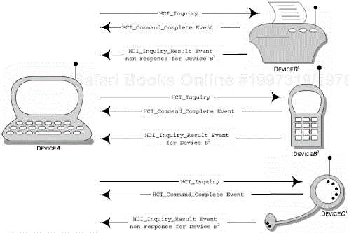
Figure 2-11 describes a sequence of events that occur when DeviceA wishes to learn of other devices in radio range. DeviceA uses the LIAC to perform the inquiry and will remain in the inquiry state for at least TGAP(100), see Table 2-18. In the illustration provided, DeviceB2 responds, whereas the other two devices have been configured for non-discoverability and general discoverability. Devices that have been configured for limited discoverability will only respond to the LIAC and, as such, are only available for a limited period of time or for specific events. Inquiring devices have the option to use GIAC or LIAC, since many circumstances may limit the response of the acceptor. Timing restrictions are applied to this operation, where the inquiry has to be completed within the time available to the acceptor during the limited discoverability (TGAP(103)).
The limited device discovery procedure obtains the same set of parameters initially retrieved by the limited inquiry. However, the limited device discovery procedure also requests the Bluetooth Device Name, although it can be obtained at a later stage during connection establishment. At the user interface level, the term Bluetooth Device Discovery is used to describe the process and in Figure 2-12, we can see the user has specifically selected the type of devices he or she wishes to see.
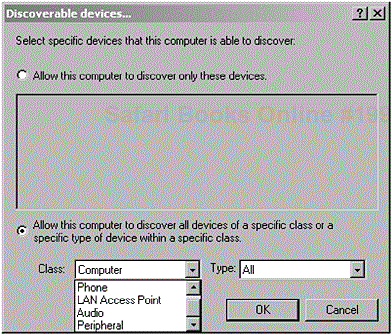
Figure 2-12. Here we can see a user configuring his or her Bluetooth device to discovery specific devices. (Courtesy of TDK Systems Europe.)
The HCI_Set_Event_Filter command is used to specifically filter out other devices during an inquiry. The command can be configured to allow only new devices to respond to a device with a certain CoD and a device with a specific BD_ADDR should only respond.
In Table 2-25 we illustrate the HCI_Set_Event_Filtercommand that is used by the host to select different event filters. As a default, the Auto_Accept_Flag is off and, as such, no filters have been defined; this flag is formed as part of the Filter_Condition_Type parameter. As part of the Filter_Condition_Type, Inquiry_Result event filter parameters, a device may be configured for all new devices to respond to an inquiry process or a device should respond with a specific CoD or BD_ADDR. A Command_Complete event is generated informing the host that the filter has been created, where an Inquiry_Result event is then generated informing the host of the results. However, the Filter_Condition_Type, Connection_Setup filter parameters enable connections from all devices or allows connections from a specific device with a CoD or a BD_ADDR. In this instance, a Connection_Request event is generated if any of these conditions are met.
In Table 2-25, we also see the parameters that make up our Inquiry_Result event filter and the Connection_Request event, which are generated as a result of defining the Filter_Condition_Type parameter. The host controller informs the host as soon as the inquiry response is received from the remote device.
Like the limited discoverable mode, the user interface describes this option as discoverable or in a discoverable mode. This mode is generally open and available with no specific conditions attached. Its use within this profile is optional, but again the governing profile may dictate otherwise.
Table 2-25. The command and event that are used in combination to create a specific inquiry result filter.
|
COMMAND |
PARAMETERS |
|---|---|
|
|
|
|
EVENT |
PARAMETERS |
|---|---|
|
|
|
|
|
|
|
|
|
The device responds to the general inquiry using the GIAC, but never responds to a LIAC when configured for general discoverable mode. Whilst in this mode, a device will enter the inquiry scan state more frequently than once in TGAP(102) and will scan for the GIAC for at least TGAP(101).
The following sections now further clarify the general inquiry and device discovery procedures for DeviceA. The behaviour of DeviceB has been presented in previous sections. Here, we want to look specifically at the behaviour of DeviceA when the device is in an idle state, that is, awaiting interaction in this particular mode of operation.
The general inquiry procedure obtains the BD_ ADDR, clock, CoD and the page scan mode of the discovered devices. Devices that have been configured for limited discovery will also respond when issued a GIAC. At the user interface level, the term Bluetooth Device Inquiry is used to describe the process in hand, see Figure 2-9. As a minimum, one inquiry procedure is mandatory, where bonding is made available—otherwise the availability of the general inquiry method is optional.
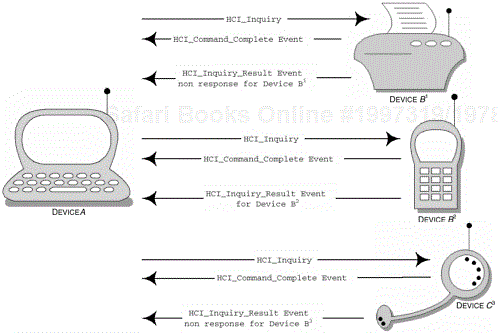
Figure 2-13 provides a sequence of events that occur when DeviceA wishes to learn of other devices in radio range. DeviceA uses the GIAC to perform the inquiry, where it will remain in the inquiry state for at least TGAP(100), see Table 2-18.
The general device discovery procedure obtains the same set of parameters initially retrieved by the general inquiry. However, the general device discovery procedure also requests the Bluetooth Device Name, although it can be obtained at a later stage during connection establishment. At the user interface level, the term Bluetooth Device Discovery is used to describe the process.
The process for which a device discovery occurs begins with a general inquiry, but the acceptor must be in a position where it can respond to this inquiry.
The mode of connectability determines whether or not DeviceA can be connected to any other device in radio range. There are several modes of operation for connectability and these will be discussed in the following sections.
In a connectable mode, the device will respond to paging, whereas a device that is configured as non-connectable will provide no response. Earlier, in Section 2.3, Profile Principles, we introduced the configurations available to DeviceA and DeviceB. Here we also learned that DeviceA would supply page trains and DeviceB would sit in the page scan state awaiting its Device Access Code (DAC).
When a device is configured for non-connectable mode, it will never enter the page scan state and, at the user interface level, it is described as non-connectable or in a non-connectable mode; its use within this profile is optional.
The bonding and pairing processes are often used synonymously, which both seem to also encompass the authentication process. The bonding procedure can be described as a user’s intent to pair, where the pairing process refers to the generation of link keys; we discuss the specific architecture of pairing in more detail in the following section. A user who wishes to connect to a remote device initiates the bonding process with his or her intent, where higher-layer procedures may be involved. More specifically, the user performs device and service discovery procedures to learn of the devices in radio range. The term bonding is used when the paging device itself chooses to initiate the pairing process. The devices that have been discovered are in a bondable state, where the user can now choose to pair with the remote device. In Figure 2-14, we show a user initiating the pairing process by selecting the pair menu option; when a user has reached this stage, it is this intent that describes the user as bonding. At the user interface level, the term Bluetooth Bonding is used to describe this process.

Figure 2-14. The user has discovered the devices in radio range and now can choose to pair with the remote device. (Courtesy of TDK Systems Europe.)
The device needs to know the DAC of the remote device it intends to bond with, which can be achieved through a device discovery. For both devices to take part in the bonding process, DeviceB should be capable of being discovered either with the general or limited discoverability modes, where the initiator then proceeds to initiate authentication. Dedicated bonding is used when the explicit generation and exchange of a link key is required, whereas general bonding, where the generation of the link key is provided under certain conditions and further initialisation is required from the higher-layers.
With the user’s intent, the remote device is also informed that a device wishes to connect to it, as we can see in Figure 2-15. If this is an unauthorised access, the user can choose to ignore this request and the initiating party will be unable to connect.

Figure 2-15. The remote device is informed of the user’s intent to pair. Both users are then presented a dialog box to enter their Bluetooth passkeys. (Courtesy of TDK Systems Europe.)
Nonetheless, if the user does know or is waiting for this connection he or she can double-click the Bluetooth icon on the taskbar to be prompted to enter the corresponding Bluetooth Passkey. Similarly, the user on the initiating part is also prompted to enter the Bluetooth Passkey for the remote device, as we have illustrated in Figure 2-16. Essentially, the two Bluetooth passkeys are entered simultaneously, where the generation of the link keys are then performed.
We introduced the Bluetooth Passkey in Section 2.4.1.3 and described the purpose of the key, where it was used to establish a trusted relationship between DeviceA and DeviceB. There are two instances that describe the process of bonding and authentication. In the first instance, the user may initiate the bonding process with the sole purpose of creating this trusted relationship. In the second instance, the user is perceived to authenticate using the passkey. The pairing process refers to the provision of the Bluetooth passkey and the link key generation procedure; authentication is then performed.
This procedure is referred to as the LMP Pairing procedure and begins when these two devices do not already share a common link key. Figure 2-17 provides a sequence of events that occur during the pairing process. To achieve this, both devices create an initialisation key, based upon the Bluetooth passkey (or PIN), a random number and the Bluetooth Device Address (BD_ADDR), see Section 2.4.1.1, Bluetooth Device Address.
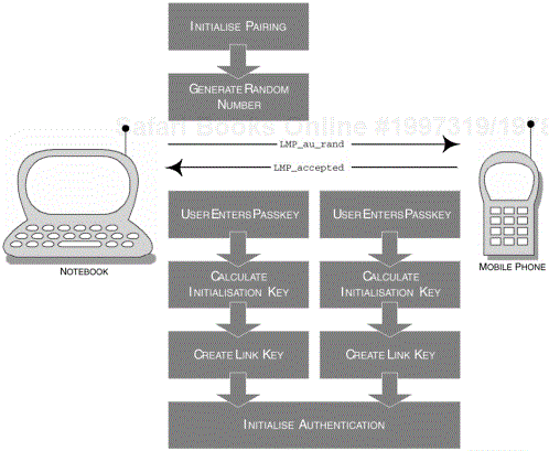
Figure 2-17. The sequence of events for the pairing process, also referred to as LMP Pairing, which leads up to the generation of the link key.
When the initialisation key is created, the link key can then be generated. The link key is then subsequently used for mutual authentication, thus allowing the devices to communicate with each other and form that trusted relationship. The two devices now share a common link key and are now referred to as bonded. Looking at the LMP commands that start this process, we note that DeviceA sends the LMP_in_rand command. DeviceB then responds with the LMP_accepted command. Both devices then proceed to calculate the initialisation key based upon the parameters provided earlier.
A combination key or a unit key is then specifically used to determine the generation of the link key, where a set of rules govern the selection process. Table 2-26 shows the LMP commands used when pairing occurs between DeviceA and DeviceB, and also shows the LMP_comp_key and LMP_unit_key, which are used when selecting a combination or unit key method, respectively.
In concluding this section, if a device is considered to be pairable then it is capable of pairing and is therefore in a pairable state. However, a device that does not accept pairing is deemed to be in a non-pairable state and therefore does not perform pairing, see Section 2.5.4.1, Pairable and 2.5.4.2, Non-Pairable.
At the user interface level, the user is presented with the configuration for the device as bondable mode or simply bondable. Its use within this profile is optional, although becomes mandatory if the bonding procedure is supported. When in a pairable state, DeviceB should respond when it receives an LMP_in_rand, with LMP_accepted or with LMP_in_rand if the device has a fixed passkey.
At the user interface level, the user is presented with the configuration for the device as non-bondable mode or simply non-bondable. Its use within this profile is optional, but the governing profile may dictate otherwise. When in the non-pairable state, DeviceB should respond when it receives an LMP_in_rand, with LMP_not_accepted, where the reason parameter should indicate pairing not allowed (0x18), see Appendix A.
Bluetooth technology is capable of offering several security modes, which we will discuss in more detail later. Firstly, the introduction of security within Bluetooth technology has become a necessity, since the availability of diverse and ad-hoc connectivity would increase the risk of unwanted intrusion within the environment it was exposed to. Once devices have authenticated, encryption may be used for the actual transfer of data, thus providing greater confidentiality in the data exchanged. In the immediate section to follow, we explore the authentication process in the Generic Access Profile context.
Table 2-26. The range of LMP PDUs available for two units when pairing.
|
PDU |
PARAMETER |
|---|---|
|
|
Random Number |
|
|
Random Number |
|
|
Authentication Response |
|
|
Random Number |
|
|
Key |
The term Bluetooth Authentication is used at the user interface level and is performed when the devices share a common link key or initialisation key. [10] You may remember in our earlier discussion that pairing occurs prior to the authentication process, which is the process of obtaining the passkey and generating the initialisation key. This process is, of course, subject to the configuration of the pairable mode, where the device can be configured not to engage in pairing.
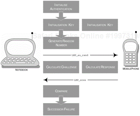
The authentication process encompasses LMP Authentication, but LMP Pairing must have been performed prior to this event. As for the LMP Authentication procedure, this is primarily based on a challenge-response scheme. Here, the verifier or DeviceA sends the LMP_au_rand command, containing a random number to the claimant or DeviceB; the random number forms the challenge aspect of this scheme. The response, forming the final part of this scheme, is sent to the verifier using the LMP_sres command, which contains the result of the operation. If the operation is what the verifier expected then it considers the claimant as authenticated.
The LMP Pairing procedure occurs when there is no link key and, as such, if an LMP_au_rand is sent to the claimant it will respond with LMP_not_accepted offering the reason as key missing (0x06), see Appendix A. If a key has been previously associated with the claimant, then the claimant proceeds to calculate the response and provides the verifier with a response through LMP_sres. However, if the calculated response is incorrect the verifier can terminate the connection with the command LMP_detach, offering the reason as authentication failure (0x05), see Appendix A; Table 2-27, summarises the LMP commands used during authentication and Figure 2-18 provides a sequence of events that occur during the LMP Authentication procedure.
This section is provided to supplement the notion of encryption introduced previously. To summarise, the process of encryption commences when at least one device has been authenticated. DeviceA (or master) takes the initiative and needs to determine whether to include encryption for point-to-point or broadcast communication. If DeviceB (or slave) is agreeable to the parameters offered by the master, the master proceeds to communicate further detailed information about the encryption parameters.
Table 2-27. The range of LMP PDUs available for authentication.
|
PDU |
PARAMETER |
|---|---|
|
|
Random Number |
|
|
Authentication Response |
|
|
Reason |
The actual process is invoked when the two parties agree to use encryption and then L2CAP communication terminates, where the master then sends the LMP_encryption_mode_req command. If this is acceptable to the slave, it too terminates all L2CAP communication and responds with the LMP_accepted command. The next step in this process actually determines the size of the encryption key and it is the master that sends the LMP_encryption_key_size_req command, where it offers an initial recommendation of the key size to use. The slave, in turn, then offers its own recommendation, where it informs the master what it thinks it might be capable of. Both master and slave will repeat this process until they reach an agreement; however, if neither party reaches a decision, then the LMP_not_accepted command is sent, offering the reason as unsupported parameter value (0x20), see Appendix A.
Upon accepting the key size, the LMP_accepted command is issued and the encryption procedure then takes place by issuing the LMP_start_encryption_req commnd with a random number, which is used to calculate the encryption key. Table 2-28 summarises the available commands for the encryption process.
The following sections now look at the various security level modes available for devices wishing to authenticate, although a device wishing to initiate authentication against another device must be at least in Security Modes 1 or 2.
At this level, a device will not initiate an authentication process—specifically, the following LMP commands are never issued:
Table 2-28. The range of LMP PDUs available for encryption.
|
PDU |
PARAMETER |
|---|---|
|
|
Encryption Mode |
|
|
Key Size |
|
|
Random Number |
|
|
None |
LMP_in_rand, LMP_au_rand and LMP_encryption_mode_req. Authentication is optional for devices that offer this level of security.
The Service Level Enforced Security tends to be moderated through the specific channel or application, providing flexibility for various applications that may be executed concurrently. As such, no security enforcement is made until the channel establishment process has been completed or at least initiated; see Section 2.6.2, Channel Establishment.
Security Mode 2 is mandatory if more than one other security mode is available, excluding support for Security Mode 1.
The requirements of the security process in this mode are categorised as authorisation: determining whether DeviceA is permitted to access the services available through DeviceB; authentication: performed by verifying the device by means of a Bluetooth passkey; and encryption: securing the data on the physical link.
The Link Level Enforced Security is the highest available security method available to a Bluetooth-enabled device, although providing limited discoverability and non-connectable modes offer additional security where limited or unwanted access is required.
Security Mode 3 is mandatory if more than one other security mode is available, excluding support for Security Mode 1.
The paging device issues the LMP_host_connection_req command since it is interested in establishing a relationship with DeviceB. However, prior to completing the connection establishment of the two devices, the LMP Pairing, LMP Authentication and encryption procedures are all executed, ensuring that all security measures have been put in place. Failure to meet with these requirements will result in the LMP_not_accepted command being issued offering the reason of authentication failure (0x05), see Appendix A, and the connection terminating.
When the devices have agreed and reached a point where no further security measures are required, both parties then issue the LMP_setup_complete command and the initial data packet can then be transmitted. Table 2-29 summarises the available commands for connection establishment.
Prior to an establishment procedure, it is assumed that an inquiry and device discovery have already been performed making available to DeviceA the various establishment parameters.
[11] We now look more closely at the availability of HCI commands that are used to create an ACL connection with the remote device. Table 2-30 shows the parameters that make up the HCI_Create_Connection command, which is used to create an ACL connection with the remote device. The BD_ADDR parameter contains the specific address of the intended device.
The Packet_Type parameter will determine what packet types will be used during the LM level connection. The information available in the Page_Scan_Repetition_ Mode and Page_Scan_Mode parameters have been previously determined during the inquiry process. One other important parameter to note is the Allow_Role_Switch. This determines whether the initiating device (DeviceA) permits the master-slave switch.
The host is issued the HCI_Create_Connection command, where the host controller then informs the host of its current status, with the Command_Status event. When the connection is successfully created between the two devices, both host controllers issue a Connection_Complete event acknowledging that the connection was successful. A unique identifier is assigned for that connection using the Connection_ Handle parameter.
The link establishment process creates a physical link between DeviceA and DeviceB and is a mandatory feature for both devices. The link establishment procedures are, to a large extent, managed at the LMP level. At the user interface level, this process is described as Bluetooth Link Establishment.
The channel establishment process creates a logical link between DeviceA and DeviceB and is an optional feature for DeviceA and a mandatory feature for DeviceB. The channel establishment procedure is managed by the L2CAP entity where, at the user interface level, this process is described as Bluetooth Channel Establishment.
Table 2-30. The command and events used in combination to create a connection with a remote device.
|
COMMAND |
PARAMETERS |
|---|---|
|
|
|
|
EVENT |
PARAMETERS |
|---|---|
|
|
|
|
|
|
The channel establishment process commences when the link establishment process has been completed. In an acknowledgment, DeviceA sends the channel establishment request L2CAP_ConnectReq, where security procedures may be invoked after the channel establishment. This process is completed when DeviceB responds with L2CAP_ConnectRsp.
The connection establishment process creates a link between the two applications that reside on DeviceA and DeviceB. At the user interface level, this process is described as Bluetooth Connection Establishment.
The connection establishment process commences when the channel establishment procedures have been completed. The specific protocol engaged between these two applications remains application-specific. It is possible for parameters of initialisation and configuration to be exchanged during this phase.
All profiles are fundamental to the Generic Access Profile.
A governing profile may change the basic requirements of the Generic Access Profile to accommodate its needs.
Rules are set out to determine the behaviour of discoverability, connectability and common characteristics at the user interface level.
Features within this profile are set out as mandatory, optional, conditional, excluded or not applicable. These may be superseded by the governing profile.
The Generic Access Profile extends its influence to the Bluetooth protocol layers, such as LMP, RFCOMM and L2CAP.
The Generic Access Profile has many configurations and roles, where different modes of operation prescribe a specific context.
This profile does not mandate specific master-slave roles, as these are left to the discretion of the governing profile.
There are several Bluetooth parameters available at the user interface level, each of which describe a particular element.
Many of the procedures undertaken at the user interface level are described appropriately to reflect their respective behaviour, such as limited inquiry, general inquiry, connectable, non-discoverable and pairable.
Pairing is the process of acquiring a Bluetooth Passkey and the generation of an initialisation key.
Bonding encompasses the procedures, which lead up to two devices being bonded.
When two devices have a trusted relationship, they are described as bonded.
Authentication is performed after the pairing process.
Authentication is based upon a challenge-response scheme.
Encryption occurs when both devices have been authenticated.
Encryption is used to protect data transmission.
There are three levels of security modes available: 1, 2 and 3.
Establishment procedures offer granularity in the connection process.
The link establishment process is used to create the physical channel.
The channel establishment process is used to create the logical channel.
The connection establishment process is used at the application level.
Multiple connections can occur between devices.
[1] The reference to foundation profiles refers to the initial set of proposed profiles that form the Specification of the Bluetooth System: Profiles, v1.1. It is used to distinguish it from the new profiles that are being proposed and may form part of a future release of the specification.
[2] The reference to governing profile is used to distinguish the requirements of the Generic Access Profile and that of another profile. The governing profile will sometimes require other features that may be mandatory, whereas the corresponding feature in the Generic Access Profile may be optional.
[3] The flexibility of the Bluetooth protocol stack, in particular the various HCI and LMP commands available, allow various methods of creating a successful ACL connection. The text refers to one particular example of a connection set-up.
[4] The Data Medium (DM) Bluetooth packet type is capable of achieving a high reliability rate.
[5] Unicode is a fixed-width standard for which 8-bit or 16-bit encoding can be used. The UTF-8 format is used to encode English characters that occupy one byte, whereas Asian or Arabic characters occupy two bytes.
[6] An FHS packet is a control packet used to reveal the BD_ADDR, clock offsets and the CoD. It is used during page and inquiry responses.
[7] The IAC is packaged into an ID packet, which is specifically used for paging, inquiry and response procedures. The ID packet has a fixed length of 68-bits and is generally robust.
[8] The LAP is one third of the Bluetooth Device Address; BD_ADDR also has two further parts: the Upper Address Part (UAP) and the Non-significant Address Part (NAP).
[9] The acceptor responds with its own native clock setting, which allows both devices to synchronise their communication.
[10] These keys are sometimes referred to as the secret key.
[11] Parameters, such as the Bluetooth Device Address, Device Name, CoD, clock and page scan mode are all used to determine whether to carry out an establishment procedure.

