
Planning
In this first chapter, we will plan the mechanical layout of a valve amplifier and find that it is determined by fundamental physics. At this stage, freedom of choice is unlimited, whereas it will later be restricted, so it is important that the choices and compromises made now are the best ones. Whilst good planning will not save a poor design, poor planning can certainly ruin a good one. Any component that requires holes to be drilled or cut in the chassis should undergo thorough electrical testing before a layout is planned – especially if the part is not current production. It is galling to discover that a component is faulty (and worse, irreplaceable) after custom metalwork has been done and wiring completed – details on component testing are given in Chapter 4.
Keywords
Cooling factor; penetration depth; electrostatic coupling; electromagnetic coupling; screening; shielding
In this first chapter, we will plan the mechanical layout of a valve amplifier and find that it is determined by fundamental physics. At this stage, freedom of choice is unlimited, whereas it will later be restricted, so it is important that the choices and compromises made now are the best ones. Whilst good planning will not save a poor design, poor planning can certainly ruin a good one. Any component that requires holes to be drilled or cut in the chassis should undergo thorough electrical testing before a layout is planned – especially if the part is not current production. It is galling to discover that a component is faulty (and worse, irreplaceable) after custom metalwork has been done and wiring completed – details on component testing are given in Chapter 4.
Chassis layout
A valve amplifier uses a number of large components needing relative positioning that minimises the length of connecting wires, yet prevents them and their wiring from interfering with each other. Chassis layout breaks down into the following considerations:
1. Electromagnetic induction: Minimising hum induction from chokes and transformers into each other and into valves.
2. Heat: Output valves etc. are hot and must be cooled. Conversely, capacitors run cool and should be kept that way.
3. Unwanted voltage drops: All wires have resistance, so the wiring must be arranged to minimise any adverse effects of these voltage drops.
4. Electrostatic induction: Minimising hum from AC power wiring is not often a problem, because even thin conductive foil provides perfect electrostatic screening, but paths should be kept as short as possible.
5. Mechanical/safety: Achieving an efficient chassis arrangement that is easily made, maintained, and used.
6. Acoustical: Almost all components are microphonic, but valves are the worst. We should consider which components are most sensitive to vibration, and minimise their exposure.
7. Aesthetic: The highest expression of engineering is indistinguishable from art. If you have a superb chassis layout, it will probably look good. Conversely, if it looks horrible, it is probably a poor layout…
We have a seven-dimensional problem. A poor transistor amplifier might be able to hide behind the fence of negative feedback, but amplifiers having an output transformer rarely tolerate more than 25 dB of feedback before their stability becomes distinctly questionable. Consequently, chassis layout is critical to performance.
The large components are generally the mains transformers, output transformers, power supply chokes, power supply capacitors, and valves. The traditional way of deciding their positioning was to cut out pieces of paper of the same size and shuffle them around on a piece of graph paper. Alternatively, the lumps themselves can be arranged and glanced at over a few days until the best layout presents itself to the viewer’s subconscious.
Finally, components can be shuffled around and a chassis designed using an engineering drawing package on a computer, with the enormous bonus that a template of the layout can be printed with all the fixing holes precisely positioned, saving errors in marking out. Although it takes time to draw a valve holder or a transformer precisely, it only has to be done once, and you will quickly build up a library of mechanical parts. In consequence, the author has almost forgotten how to perform traditional marking out using a scriber, ruler, and square.
It is vital to make the chassis large enough!
This point cannot be emphasised too strongly. Achieving neat construction on a cramped chassis requires a great deal more skill and patience than on a spacious chassis. There are many considerations that must be taken into account, so it is vital that this stage is not rushed. Each of the following design considerations might not make a great difference in itself, but the sum of their effects is the difference between a winner and an “also ran”.
Electromagnetic induction
Almost all of the larger components either radiate a magnetic field or are sensitive to one. Not all of a transformer’s primary flux reaches the secondary, so leakage flux might induce currents into grid wiring, thereby developing voltages across associated resistances. Whether or not these currents and voltages are significant depends on the signal level and source impedance at that point, so output valves are less of a problem than the input stage.
Coupling between wound components
Wound components such as transformers and chokes can easily couple into one another, so hum can be produced by a mains transformer inducing current directly into an output transformer. Fortunately, the cure is reasonably simple, and may be summarised by a simple ratio whose value must be minimised:
![]()
The angle θ and distance d are shown in the diagram. See Figure 1.1.
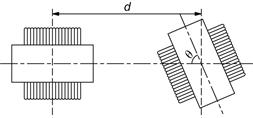
Rotating transformer cores by 90° (cos 90°=0), so that the coil of one transformer (or choke) is not aligned with the other is very effective, and typically results in an immediate 25 dB of practical improvement. Even better, if one coil is driven from an oscillator whilst the interference developed in the other is monitored (oscilloscope or amplifier/loudspeaker), careful adjustment of relative angles can often gain a further 25 dB.
Because coupling decays with the cube of distance [1], as the distance between offending items is increased, the interference falls away rapidly. However, simply increasing the gap between two adjacent transformers from 6 to 25 mm does not materially reduce the interference, because the transformers are typically 75 mm cubes, and the spacing that applies is the distance between centres, which has only changed from 81 to 100 mm, resulting in only 5.5 dB of theoretical improvement. Unfortunately, when large transformers are this close, coupling no longer obeys the inverse cube law because the dipole equation upon which it is based carries the implicit assumption that the separation is much greater than dipole length, so a 3 dB reduction, or less, is more likely.
Another consequence of size is that if other layout considerations force an output transformer and mains transformer to almost touch, we should not only ensure that their coils are at right angles to one another, but also align their centres. When the centres are aligned, each edge of one coil induces significant current into the receiving coil, but because the edge distances are the same, their induced currents are equal and opposite, so cancel. But if one transformer is slid to one side (whilst remaining at right angles), the edge distances differ, complete cancellation no longer occurs, and increased induction results.
Be aware that the previous argument of edge distance equality and consequent cancellation assumes that the transformer manufacturer made each winding fill complete layers. They usually do, because it avoids difficult winding, but a dual chamber bobbin having the mains primary in one chamber and secondaries in the other destroys this fundamental assumption and only testing can determine its optimum orientation.
Although smoothing chokes are gapped, and therefore inevitably leaky, they don’t generally have much alternating voltage across them, so their leakage is low, and they can often be used to shield output transformers from the mains transformer. The exception to this rule is the choke input power supply, which has a substantial alternating voltage across its choke, so its leakage field can be significant.
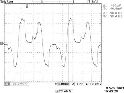
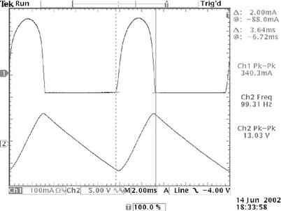
A poorly designed mains transformer’s core can easily be saturated by the large current pulses drawn by a large reservoir capacitor in combination with a semiconductor rectifier, producing a particularly ragged leakage flux, and this can be quickly identified using a search coil (see Chapter 4 for details on search coil construction). See Figure 1.2.
Shielding
The effectiveness of magnetic shielding is determined by the ratio of the shield’s thickness to penetration depth, so we must minimise penetration depth [2]:
![]()
Minimising penetration depth means maximising the denominator, so our first observation is that low frequencies (<100 kHz) have large penetration depths and will therefore be difficult to shield; <100 kHz it is always better to avoid leaking flux than it is to attempt to shield it.
Unsurprisingly, the equation also tells us that magnetic shielding is best achieved using a magnetic material (such as steel), but it also tells us that magnetic shielding can be obtained at high frequencies simply by a good conductor, such as aluminium or copper.
Thus, we can expect a thin steel shielding can enclosing a transformer to mainly attenuate the high frequency component of its leakage flux. The second guilty party is a 50-year-old mains transformer whose core material has deteriorated, but is screened by a thin steel can resulting in a leakage waveform having smoothly rounded edges, indicating far less high frequency content than the first example. See Figure 1.3.
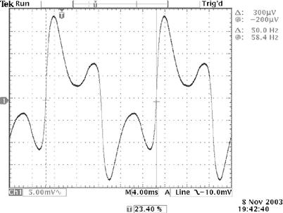
A little of the second example’s shielding was due to the ferrous shield diverting and containing leakage flux, but the majority was due to losses. Hysteresis and eddy current losses become more significant as frequency rises (even if the loss per cycle remains constant, there are more cycles per second to dissipate energy). Further, as frequency rises, wavelength falls, and more loops become possible in a given distance. Eddy current losses are conduction losses, so the shield’s electrical resistance should be minimised, making 2 mm copper or 4 mm aluminium very effective >100 kHz.
Another transformer shielding possibility that relies on losses is the Faraday shield. See Figure 1.4.
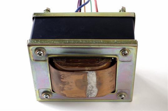
The wide copper strap provides magnetic shielding because it is a shorted turn to the transformer’s leakage flux, and this is why it wraps around the entire core rather than the core’s central leg. The shield’s effectiveness is determined by its electrical resistance and the proportion of intercepted leakage flux, so the foil firstly needs sufficient cross-sectional area to have low resistance and be an effective shorted turn, and secondly needs to enclose as much of the transformer as possible. The ideal Faraday shield would be a tube much longer than the transformer, but practical considerations generally limit it to the width of the windings. A Faraday shield can be retrofitted to any EI transformer provided care is taken:
• Ensure that the shield does not short-circuit or contact with existing windings, perhaps by touching tags.
• Soldering the ends of the copper strip to complete the shorted turn involves heat, so ensure that the heat can’t damage insulation beneath it, perhaps by placing a thin strip of sacrificial cardboard beneath the joint and removing it after soldering.
Interestingly, the copper foil need not be very thick (0.001″ or 0.025 μm) to constitute a shorted turn (≈5 mΩ), and practical Faraday shields of the same copper thickness all have roughly the same resistance, regardless of transformer size. This occurs because although a larger transformer requires a longer shorted turn, the required foil width rises proportionately.
The 0.5-mm-thick Faraday shield shown in Figure 1.4 appears over-engineered by a factor of 20, but the increased thickness may perhaps be explained by the fact that the transformer was salvaged from a receiver that would have needed careful radio frequency shielding.
Transformers and the chassis
We have seen that all transformers leak flux and that shielding is difficult. The question is whether the leakage flux is a problem. If an output transformer leaks flux into the aluminium chassis of a power amplifier, it probably isn’t a problem because aluminium doesn’t conduct magnetic flux. But a mains transformer leaking flux into the steel chassis of a pre-amplifier is a problem because the steel chassis passes the flux into sensitive signal circuitry. Fortunately, because μr≈1 for non-magnetic materials, but μr>5000 for steel, even a small gap is able to prevent flux leaking into a steel chassis; 1.6 mm ![]() plain phenolic sheet is ideal, but may be hard to find, so practical alternatives include the decorative printed phenolic sheet found in DIY stores, or 3 mm (⅛″) acrylic.
plain phenolic sheet is ideal, but may be hard to find, so practical alternatives include the decorative printed phenolic sheet found in DIY stores, or 3 mm (⅛″) acrylic.
Beware that although toroidal transformers are the theoretically perfect shape, practical toroids leak flux, and that mounting a toroid directly onto a steel chassis is asking for hum problems. As before, plastic sheet provides enough of a magnetic gap to significantly reduce induction. However, the danger of accidentally creating a shorted turn is considerable. Toroids are usually secured by a conductive screw pulling a large conductive washer onto the opposite face of the core to clamp the transformer tightly to the chassis. Accidentally connecting the washer or screw to the chassis by any means other than the bottom of the central mounting screw constitutes a shorted turn that could destroy a power transformer. If there is a possibility of the washer contacting chassis, break the conductive path through the screw. Either use a nylon screw (not ideal because the small cross-section of nylon stretches easily), or use a pair of metal screws separated by a substantial threaded plastic boss (the boss’s far larger cross-sectional area is less liable to stretch and weaken the clamping force).
Beam valves and mains transformers
Beam valves deliberately focus their current into thin sheets that pass largely unintercepted between the horizontal wires of g2, thus improving efficiency. This means that a vertical beam deflection would affect g2 current, and because g2 is typically supplied from a finite source resistance, Ohm’s law ensures that this would change Vg2, thus changing Ia. One way of deflecting electrons is with a magnetic field, such as the leakage flux from a transformer. Hum due to beam deflection can be minimised by applying Fleming’s left-hand rule, and ensuring that the electron beam is never at right angles to the leakage flux from the transformer. When considering induction between two transformers, it did not matter which transformer was rotated, so long as the coils were at 90° to one another. With beam valves, only one orientation is ideal with respect to a nearby mains transformer. See Figure 1.5.
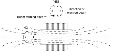
The valve is shown in two positions, both the same distance from the centre of the mains transformer, and with correct beam orientation relative to the leakage flux from the transformer. However, leakage flux tends to be concentrated on the axis of the coil, and would also induce hum into the control grid’s circuit, whereas the alternate position has much lower flux density. (Diagrams of this form portray higher flux density by having more lines in a given area.)
Input valves are very sensitive to hum fields, and should always be placed at the far end of the chassis to any mains transformer.
In theory, output transformers should leak less flux because they operate at a lower flux density (to avoid saturation and consequent distortion) and are designed for minimum leakage inductance (which translates directly into reduced leakage flux). In practice, probing output transformers and mains transformers with a search coil failed to show the expected difference. The quality of the transformer seems to be the overriding consideration, rather than its use. Thus, a Leak TL12+ push–pull output transformer leaked more flux than a good quality modern output transformer in a single-ended amplifier, despite the latter being gapped.
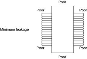
Although, as expected, leakage flux at 90° to the coil’s axis cancels to zero, leakage at the edges of the coil can be comparable with that on axis because the coil’s outermost turn is so far away from the (flux-concentrating) core. See Figure 1.6.
Heat
Heat is the enemy of electronics. Output transformers and chokes are usually quite cool, so they can move towards the centre of the chassis if necessary (creating a mechanical problem, but we will consider this later). Mains transformers are generally warm, and mounting them towards the edge of the chassis assists cooling.
Heat shortens insulator life and causes components to drift in value. At worst, it causes fires. And we intend to use valves, which are deliberately heated…
Modes of cooling
Heat can only flow from a body having a higher temperature to one having a lower temperature, and flows until there is no temperature difference between them. There are three ways of transferring heat.
Conduction is the most efficient way of transferring heat and requires a conducting material to bond the heat source physically to its destination. An ideal conductor transfers heat with a minimal temperature drop between source and destination, and materials having free electrons (electrical conductors) such as copper and silver are particularly good. The body of a power transistor must conduct the heat generated by the (very much smaller) silicon die to an external heatsink. See Figure 1.7.
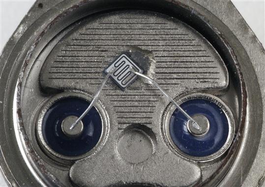
Figure 1.7 The inside of a 2N3055 15 A/115 W power transistor. Note the relative size of the silicon device and its wires compared to the case.
One of the reasons that the previous steel TO-3 package has been made obsolete by epoxy packages is that their copper tab interposes far lower thermal resistance between the silicon die and heatsink.
Temperature drops caused by the flow of conducted heat through a thermal resistance can be calculated using:
![]()
T=temperature in kelvin (or °C)
P=thermal power to be transferred
Rthermal=thermal resistance (often given by heatsink manufacturers in °C/W).
If we need to conduct heat through a bar of uniform cross-section, we can calculate its thermal resistance using:
![]()
As can be seen from Table 1.1, copper is only fractionally worse than silver (the best), but much better than aluminium, and iron (or steel) is poor.
Table 1.1
Thermal conductivities of metals at 20°C
| Conductivity (W/m/K) | |
| Silver | 428 |
| Copper | 403 |
| Gold | 319 |
| Aluminium | 236 |
| Iron | 84 |
As an example, suppose that we have bonded a TO220 device dissipating 4 W to the end of an aluminium bar of ½″ by ¾″ cross-section and 50 mm long, whose far face is thermally bonded to a large heatsink. How much of a temperature drop will we suffer along the bar?
We must first convert the units into metres (1″=25.4 mm), so ½″ becomes 0.0127 m, ¾″ becomes 0.01905 m, and 50 mm becomes 0.05 m. We can now drop these numbers into the thermal resistance equation:
![]()
Knowing that we wish to transfer 4 W, a thermal resistance of 0.88°C per watt will cause a temperature drop of 3.5°C. The significance is that although the heatsink might operate at 40°C, the TO220 device will be 3.5°C hotter at 43.5°C. If an insulating kit is used, this will add its temperature drop, and if you really want to carry the calculation through, semiconductor manufacturers generally specify thermal resistance between die and mounting tab, so the die temperature could be calculated and compared to manufacturer’s recommendations.
Convection relies on the heat-carrying movement of a fluid (gas or liquid) between source and destination. Fluid is heated at the source, expands, and is displaced by denser cooler fluid, forming a convection current that continuously pushes hot fluid away and draws cool fluid towards the source. Convection efficiency can be increased in various ways:
• If a greater volume of fluid moves per second, more heat can be transferred, so the forced convection of a computer fan greatly improves heat transfer over natural convection.
• We choose a fluid having a higher specific heat capacity – meaning that it absorbs more heat energy for a given temperature rise. Liquids are better than gases, and water is especially good, so pumped water cools most internal combustion engines.
• We choose a fluid that can support a higher temperature before boiling, increasing heat transfer. A few nuclear power stations pressurised water to raise its boiling point, and more extreme reactors pumped liquid sodium (883°C boiling point).
• Although some transmitter valves had water-cooled anodes, practical pipe diameters and required pump power imposed a practical limit to the maximum flow rate, and thus the heat that could be transferred. However, changing the state of a material requires a great deal of energy, and converting water at 100°C to steam at the same temperature requires seven times as much energy as heating that same mass of water from 20 to 100°C so, paradoxical as it may initially seem, the very largest transmitter valves were steam cooled.
Radiation (strictly, electromagnetic radiation) does not require a physical medium between heat source and destination, but it is the least efficient means of transferring heat. Radiation losses are governed by Stefan’s law:
![]()
Conventionally, body 1 is set to be the hotter body, but a negative result indicates that heat is flowing from body 2 to body 1. Unless the two temperatures are quite similar, very little error is caused by neglecting the cooler body temperature. Because heat flow is proportional to the fourth power of temperature, particularly hot bodies such as the Sun (surface temperature ≈ 6000 K) can transfer heat quite effectively by radiation.
Valve cooling, positioning, and cooling factor
Output valve anodes are hot and, unless adequately cooled, will heat their micas sufficiently to cause outgassing of water vapour that poisons cathodes. Typical audio valves isolate the hot anode within an evacuated glass envelope, so the anode cannot lose heat by convection. The supporting wires from the anode to the outside connectors are quite thin, so the anode cannot lose heat by conduction. The only remaining method of heat transfer is radiation.
Radiation obeys reciprocity, so a good emitter is also a good absorber. Thus, domestic kettles are shiny metal or white plastic because reflective surfaces that don’t absorb heat are also poor emitters. Conversely, matt black absorbs heat well, so anodes are darkened to enable them to radiate infrared (heat) more efficiently. Although we think of glass as being optically transparent, some light is inevitably lost in transmission, and glass is imperfectly transparent to infrared radiation. Radiation that is not passed is absorbed and heats the glass envelope, so some of the received heat from the anode can be lost by convection if air is allowed to flow freely past the valve envelope. Very roughly, the glass envelope splits valve thermal losses equally between convection and radiation. Thus, efficient cooling requires that we consider how the anode can radiate, and how easily convection currents can flow past the envelope. Many valve data sheets specify the maximum tolerable envelope temperature – usually 180 or 200°C for consumer valves, but some industrial valves (such as the 6528) will tolerate 250°C.
Power valves should separate their centres by a spacing of at least twice their envelope diameter, otherwise they heat each other by radiation. But a useful trick can be applied to the radiant heat received by a valve. Many valves, particularly small-signal valves, have an anode with quite a narrow cross-section. Total received radiant heat is proportional to the area seen at the destination, so rotating a valve to present a narrow cross-section to the source can reduce heating from adjacent power valves. By reciprocity, if the source also has a narrow cross-section, rotating the source to present a small area to the destination also reduces transmission. This technique is particularly useful for circuits such as differential pairs or phase splitters where electrical considerations dictate that the two valves almost touch, but it can also be used to safely reduce the distance between a driver valve and a power valve. See Figure 1.8.
Placing power valves in the middle of a chassis is unlikely to be a good idea because the chassis severely restricts convection currents. Mounting a valve horizontally can improve convection efficiency because it exposes the valve to a larger cross-section of cooling air. However, this could conceivably cause a hot control grid to sag onto the nearby cathode, with disastrous results, so check the manufacturer’s full data sheet to see if there are any strictures about mounting position. If it doesn’t cause other problems, align the socket so that the plane of the grid wires is vertical [2], preventing them from sagging onto the cathode.
Early valves had cylindrical electrodes, so viewed down their axis, electrons strike the anode equally from all points of the compass. Since the electron density is equal at all angles, the anode temperature is also equal at all angles. However, beam tetrodes do not have axial symmetry, and direct their beam of electrons along a single diameter, causing the anode to heat unequally. Bearing in mind that the glass envelope converts half of the radiant heat loss from the anode to convection loss from the envelope, a horizontally mounted beam tetrode should be rotated on its axis so that the hottest parts are at the sides, allowing them to be efficiently cooled by convection, rather than at top and bottom. As an example, see GEC’s recommended alignment for the KT66 [3]. See Figure 1.9.
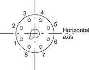
Because the sections of a KT66’s envelope between pins 1 and 2, and 5 and 6 are the hottest, when mounting a push–pull pair of KT66 vertically, it makes sense to ensure that pins 7 and 8 of one valve face pins 7 and 8, or 3 and 4, rather than 1 and 2, or 5 and 6.
Mounting valve sockets on perforated sheet metal greatly assists cooling by allowing a convection current to flow past the valve, but as the hole area of sheet metal is typically only ≈40%, it is still not perfect. If better cooling is needed, the valve socket can be centrally mounted on a wire fan guard, and if even that isn’t sufficient to keep the envelope temperature below the manufacturer’s specified maximum, a low-noise fan can be mounted on pillars underneath the chassis using the same screws that secured the fan guard. See Figure 1.10.
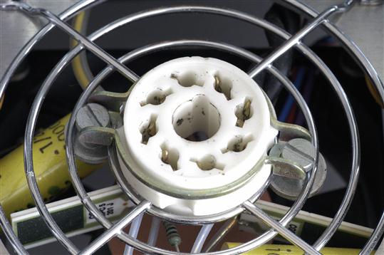
Figure 1.10 With care (and large washers), a valve socket can be mounted on a fan guard, allowing almost unrestricted airflow.
The degree of care we must take over convection currents is dependent upon the ratio of envelope surface area to anode dissipation, so a very useful figure of merit based on these factors may be calculated as follows:
![]()
A wide range of valves was deliberately selected, anode height measured, then sorted by cooling factor. See Table 1.2.
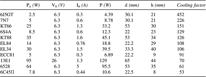
Unsurprisingly, older designs have more conservative cooling factors, and putting two identical triodes in the same envelope halves the cooling factor (7N7 vs. 6J5GT). More significantly, based on the table and practical experience, provided that the valves are mounted on an open chassis (not inside a box where ambient temperature can rise), the following observations may be made relating to cooling factor:
>150: No special precautions other than common sense necessary.
≈150: Enforce exclusion zone* of 2×envelope diameter.
≈130: Enforce exclusion zone of 3×envelope diameter.
≈110: Allow 40% unrestricted air flow. This might be done by moving the valve to the very edge of the chassis (almost half the flow unrestricted), or mounting the valve on perforated metal (typically 40% hole area).
≈90: Enforce >3×exclusion zone and 40% air flow.
≈70: As above, but lift the chassis >20 mm above supporting surface to allow cooling air to convect freely from underneath.
<70: As above, but add a fan directly below the valve to force cooling.
Table 1.2 sets Pa=Pa(max), but valves are not always operated at full anode dissipation, so calculation at a valve’s actual anode dissipation might usefully improve its category.
Referring back to Table 1.2, it will be seen that whereas GEC specified 4″ between KT88 centres (corresponding to 2×envelope diameter exclusion zones), the author suggests a slightly more conservative 3×for these rare and valuable NOS valves. It will also be seen that if the 6C45Π’s rating is continuous, it is either wildly optimistic or assumes forced cooling.
Using the chassis as a heatsink
We have previously considered how we can transfer heat from source to destination, but if the destination has finite mass, we must eventually raise its temperature, reducing the temperature difference and consequent heat flow. Early transmitters transferred their waste heat to outdoor cooling ponds, giving them access to the (by comparison) infinite mass of the planet’s atmosphere (≈5.3×10¹⁸ kg). Domestic amplifiers necessarily treat the surrounding air as an infinite mass, but we must ensure that access to this air is not restricted.
Some small components, such as power resistors and regulator ICs, unavoidably generate significant heat. Small resistors are commonly mounted on stand-offs to allow an unimpeded air flow, and regulators are often fitted with small-finned aluminium heatsinks. Neither of these strategies is ideal because they attempt to lose heat by convection to the very limited mass of air trapped within the chassis, quickly raising its temperature. Eventually, the trapped air loses heat by conduction to the cooler chassis, and thence the surroundings, so an equilibrium results with a high internal air temperature and hot components.
A high air temperature within the chassis is undesirable because:
• The components causing the high air temperature are unnecessarily hot, and even though they may have been designed to withstand heat, their working life is invariably reduced.
• Electrolytic capacitors are especially sensitive to heat, and a very rough rule of thumb is that their working life halves for each 10°C rise in temperature. Capacitor manufacturers’ data sheets include extremely useful charts that allow lifetime predictions to be made from ambient temperature and capacitor ripple current, so it is well worth looking up the full data sheet for your particular capacitor at the manufacturer’s website.
• Components having a critical value, such as in equalisation or biasing networks, will drift from their initial value as a consequence of heating.
Ultimately, we can only lose heat to the surrounding air, and a large surface area cools more efficiently. This means that the best way to cool components is to ensure that they are thermally bonded to the chassis, using a thin smear of heatsink compound. Heatsink compound is not a particularly good conductor of heat, but it is far better than air. The purpose of heatsink compound is to fill the tiny insulating air gaps that result from placing two imperfectly smooth surfaces together. Excessive compound worsens cooling. Most people (and this includes manufacturers) use far too much. A thin, even smear applied to both mating surfaces is all that is required.
Beware that mismatch between the thermal coefficient of expansion of screws and heatsink bonded to the chassis could loosen them at operational temperature, so check tightness when fully warmed, otherwise the compromised thermal bond can cause semiconductors to be hotter than expected and, worse, an erratic bond causes drift. Conversely, mismatch in thermal expansion between the semiconductor’s package and its fasteners that causes tightening could crack the package; spring washers and clamps are available for maintaining optimum force at all temperatures.
A useful secondary advantage of mounting aluminium-clad or TO220 resistors directly onto the chassis is that they provide convenient mounting tags for other components. It may seem unnerving to touch a chassis with hotspots due to local heatsinking, but this technique minimises the internal air temperature, and thus minimises the heating of sensitive components.
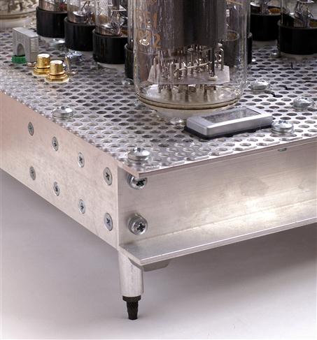
Efficient convection requires a free flow of cool air to replace hot air. Although most designers recognise the importance of allowing adequate ventilation by providing holes in the top of a chassis near hot components, air must also be free to enter the chassis from the bottom if an efficient convection current is to flow. Thus, the ideal solution is to make the entire underside of the chassis from perforated steel or aluminium, and support it on feet ≈20 mm high (to allow air to flow unimpeded into the underside of the chassis). See Figure 1.11.
If necessary, individual components can be cooled even more efficiently by bonding them directly to a finned heatsink fitted outside the chassis, as is common with transistor amplifiers. See Figure 1.12.
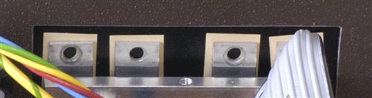
Figure 1.12 Cutting a hole in this steel chassis allowed the power transistors to contact the heatsink directly. Note also the clamp that applies pressure to the epoxy package rather than the protruding tab.
Although heatsinking most obviously springs to mind when considering large power amplifiers or power supplies, precision pre-amplifiers must minimise their internal temperature rise in order to prevent equalisation networks drifting in value, so it may be worth thermally bonding anode load resistors to the casing or an external heatsink.
When finned heatsinks are used, it is essential to orient them correctly. Heatsink manufacturers specify thermal resistance (°C/W) with the fins vertical in free air because this maximises the surface area available to the natural cooling convection current flowing up the fins. Despite this, the author has lost count of the number of commercial amplifiers having horizontal heatsinks. Heatsinks cost money, so why degrade their performance? The prettiest example that the author can find showing the importance of correct fin orientation is a motorcycle. See Figure 1.13.
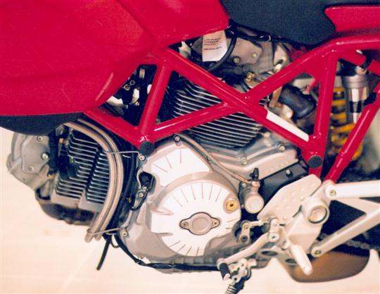
Figure 1.13 This air-cooled Ducati motorcycle has barrels with fins aligned in the direction of air flow.
The engine is an air-cooled V-twin. The pistons are identical and run in barrels that are detachable from the crankcase. Despite the increased production cost, the two barrels are different, one having longitudinal fins, the other latitudinal, and this is done solely to optimise cooling. Your amplifier fins cannot achieve a forced 100 mph horizontal convection current, so they need to be vertical.
Cold valve heater surge current
The resistance of a conductor such as a valve heater filament changes significantly with temperature in accordance with the following equation:
![]()
RT=resistance (Ω) at temperature change T
α=thermal coefficient of electrical resistance (≈0.005 per °C for pure tungsten)
Normally the temperature rise of conductors in electronics is too small for the effect to be noticeable, but a thoriated tungsten filament operates at ≈1975 K, so at an ambient temperature of 20°C (293 K), its resistance is much lower, and theory predicts that it very briefly draws 8.6 times the operating current. In practice, surge current is limited by heater supply output resistance, perhaps to only half the predicted value.
Indirectly heated valves operate their filaments at ≈1650 K, resulting in a theoretical surge current of ≈7 times the operating current, although measurements suggest that a ratio of ≈5:1 is more appropriate. More significantly, the thermal inertia of the cathode sleeve slows heating, so the surge current lasts for a few seconds, and could be sufficient to blow a poorly chosen mains fuse. Further, it would not be prudent to use heater wiring of a rating only just sufficient to cope with the steady-state current if long-term reliability were required.
Wire ratings
Wires have ratings related to heat because electrical insulation deteriorates with increased temperature and the internal conductor has resistance, so passing a current causes self-heating (P=I2R).
Arcing and insulation failure should not be a problem at the voltages found within most valve amplifiers, but it is still advisable to maintain 2–3 mm separation between high voltages, and it is particularly important to prevent wires carrying high voltages from touching hot components – leads to anode top caps must not touch the (hot) valve envelope. Less obviously, avoid routing wires near hot resistors.
If a wire becomes too hot, its impaired insulation may leak current between circuits leading to impaired performance and possibly fire, so it is important to ensure that the wiring is rated appropriately for the current to be passed. This means that wire current ratings are determined by ambient temperature, ability to cool, and the temperature rating of the insulator. See Table 1.3.
Table 1.3
Typical current ratings for PVC insulated wire
| Conductor diameter (mm) | Maximum current (A) | AWG |
| 0.6 | 1.5 | 22 |
| 1 | 3 | 18 |
| 1.7 | 4.5 | 14 |
| 2 | 6 | 12 |
PTFE has a higher melting point than PVC, permitting greater self-heating and thus a higher current rating than might be expected from a given conductor diameter, but the penalty of using a small-diameter conductor (having higher resistance) at high currents is that voltage drops along that wire are proportionately higher, and this can become significant within the capacitor/rectifier/transformer loop of a power supply.
Unwanted voltage drops
All wires have resistance that is proportional to their length and inversely proportional to their cross-sectional area. Although the currents in valve circuitry are typically quite low, making the voltage drops proportionately low, once we consider that we want a signal-to-noise ratio of >90 dB, the voltage drops caused by small resistances become significant.
The highest currents, and therefore highest voltage drops, occur in the loop from transformer via rectifier to reservoir capacitor and back again. A capacitor input filter draws pulses of current at twice mains frequency from the transformer that are typically four to six times greater than the DC load current. It is essential that the wires carrying these pulses are as low resistance, and therefore as short as possible, which means that the rectifier and associated reservoir capacitor should be close to its mains transformer. It’s the same logic that puts the battery in a car’s engine compartment. (The 1959 Mini was intended to be conventional rear wheel drive from a 500 cc longitudinal engine, but this proved to be underpowered, so the only way to fit a larger engine was to mount it transversely and adopt front-wheel drive, but that left insufficient room for the battery, forcing it into the boot, requiring a long, very thick wire to the starter motor.)
When an output stage enters Class B, it draws current pulses at twice the audio signal’s frequency from the power supply. To prevent these pulses breaking into driver circuitry and increasing distortion, the loop area from audio load to reservoir capacitor should be as small as possible. This means that output transformers should be close to their supply capacitor.
The potential effects of unwanted voltage drops usually determine the 0 V signal earth scheme, often known colloquially as earthing or grounding. There are two fundamental methods of dealing with earthing:
• “Earth follows signal.” The 0 V signal earth wire follows the path of the signal. In order to minimise unwanted voltage drops along this (necessarily long) wire, it has a large cross-section so this brute force strategy leads to 1.6 mm tinned copper bus-bars.
• Star earth. All connections to the 0 V signal earth are made at a single point. Because the distance between individual connections is so small, the common impedance is small, so unwanted voltage drops are also small.
The significance of these two wiring schemes is that the choice between them needs to be made at a very early stage. “Earth follows signal” tends to favour long, slim mechanical layouts, whereas an ideally implemented star earth tends to favour square or even circular layouts centred about the star earth. The significance of unwanted voltage drops is so great that it dominates the gross mechanical layout of an example later in this chapter, whilst detailed electrical implications will be covered in Chapter 3.
More powerful amplifiers are heavier, and in an effort to split the weight into a pair of manageable chassis, you might consider having a remote power supply, necessitating an umbilical connecting cable. Beware that the umbilical wires need a larger cross-section than within a single chassis in order to minimise the unwanted voltage drop over this increased distance, perhaps needing an umbilical connector having a larger diameter cable entry.
Electrostatic induction
Electrostatic coupling is capacitive coupling. Minimising the capacitance between two circuits minimises the interference. Remembering the equation for the parallel plate capacitor:
![]()
ε0=permittivity of free space ≈ 8.854×10⁻¹² F/m
εr=relative permittivity of dielectric between plates (typically 2–3 for plastics)
When capacitance must be minimised between two points, all parts of the equation should be attacked. Reducing plate area means keeping wires short and crossing them at right angles, whilst increasing plate distance means maximising separation of parallel wires and not lacing them together into a neat loom. In terms of chassis layout, this means that output valves should be reasonably close to the output transformer and that driver circuitry should be reasonably close to the output valves.
A layout having minimum electrostatic induction tends to have such short wiring that the circuit looks very simple. If your planning seems to require many long wiring runs, try another arrangement of the large components or input/output connectors. In particular, mains wiring should be kept as short and compact as possible, not just to minimise interference but also to minimise the risk of accidental contact if faultfinding becomes necessary.
In a high impedance circuit such as a constant current sink, a chassis-mounted transistor causes a conflict between thermal and electrostatic considerations because the collector is invariably connected to the transistor case. Fastening a TO-126 transistor such as an MJE340 to an earthed chassis using an insulating kit adds 6–8 pF shunt capacitance, degrading any efforts we may have made to design a wide-bandwidth constant current sink. In this instance, we are forced to compromise our thermal considerations and lose heat directly to the air within the chassis using a small finned heatsink.
Fortunately, capacitance to chassis from aluminium-clad or transistor-style resistors used as anode or cathode loads is rarely a problem at audio frequencies. Because one end of the resistor is at AC earth, but the capacitance is distributed along the resistor element, the total element to earth capacitance is effectively halved, and because the impedances are lower than in a constant current sink, the stray capacitance becomes insignificant.
Valve sockets
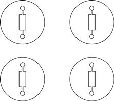
A wide variety of valve sockets is available for a given valve base. See Figure 1.14.
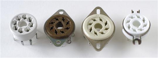
All three of the chassis-mounting International Octal sockets in the photograph have different spacings for their securing screws, so it is vital to make a firm decision about which socket type is to be used, and whether the circuit is to be hard-wired or printed circuit board. One point that may be worth considering when choosing Octal sockets is that NOS McMurdo phenolic sockets have the same hole spacings as Loctal sockets, allowing an easy change from 6SN7 to 7N7 at a later date.
Another consideration is heater wiring positioning. Taking the B9A base as an example, most valves using this base have their heaters connected between pins 4 and 5, so the socket should be rotated to position these pins closest to the heater run. Note, however, that operating the popular ECC83/12AX7 from 6.3 V requires a link between pins 4 and 5, and for minimum hum the other heater wire should be taken across the centre of the socket to pin 9 – do not loop it round the outside. McMurdo B9A valve sockets were designed so that if the line joining the two socket fasteners was aligned at 45° to the edge of the chassis, pins 4 and 5 were closest to the chassis edge, minimising hum from heater wiring. See Figure 1.15.
Figure 1.15 McMurdo B9A sockets position the heater pins (4, 5) close to the edge of the chassis provided that the mounting holes are at a 45° angle to the edge.
Traditional valve amplifiers always had their valve sockets aligned so that heater pins were closest to the chassis edge, thus minimising the length of exposed heater wiring.
How electrostatic screening works
Electrostatic screening places an earthed conductive barrier between the source of interference and the sensitive circuit. See Figure 1.16.
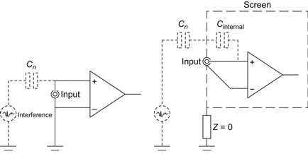
As can be seen from the diagram, the screen diverts interference currents from the source to earth. If there is an impedance between the screen and radio frequency earth, the interference current must develop a voltage across it, allowing the screen to capacitively couple interference to its enclosed (sensitive) circuitry.
The impedance from the screen to radio frequency earth can be considered to be the lower leg of a potential divider, and the capacitance from the screen to the interference source is the upper leg. The lower leg could be a length of conductor, which has inductance, thus forming a 12 dB/octave filter in conjunction with the capacitor. To maximise screening efficiency, the screen needs a path to chassis having low resistance and low inductance. When resistances and inductances are connected in parallel, the total value falls, so the screen should ideally contact the chassis at multiple points to minimise impedance and maximise screening. This is why radio frequency designers cut the flanges of the lids containing their circuitry – it ensures that each finger firmly contacts the case, and minimises radio frequency impedance to all points of the screen. See Figure 1.17.
From an audio point of view, screening cans should be firmly screwed to the chassis at multiple points using serrated washers to ensure a gas-tight connection that does not deteriorate over the years. Pre-amplifiers using choke inter-stage smoothing should ideally use oil-filled chokes, not because the oil confers any advantage, but because the metal can that contains the oil provides electrostatic screening.
Valves that are sensitive to electrostatic fields can be enclosed by an earthed metal screening can, but screening cans are not created equal. Perfect screening would enclose the valve completely, but that would prevent heat from escaping, making the valve significantly hotter, and reducing its life [4]. It is easy to raise a valve’s temperature, but lowering it is much harder, so a screening can must always strike a compromise between screening and cooling. See Figure 1.18.
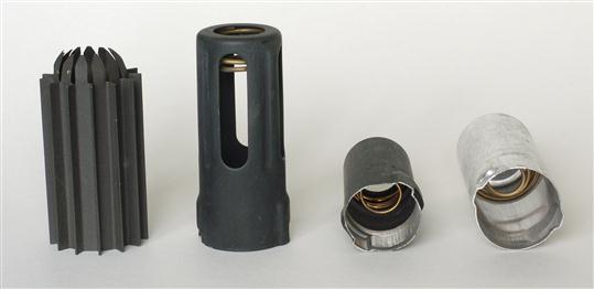
From left to right
The first “screening can” was actually manufactured as a heatsink, and slightly reduces envelope temperature. All that is needed to turn it into a screen is a short wire to bond it electrically to the chassis. The dungaree screening can has a bayonet fitting onto a skirted base and holes allow air to flow, which reduces its screening efficiency and temperature rise. Note that the can’s inside is painted matt black to absorb radiant heat from the valve, which is then re-radiated by the black outside. The third can is for small-signal valves only as airflow is very restricted, but the black paint inside and outside assists cooling. The fourth can is an abomination that deserves to be crushed because not only does it restrict airflow, but it also reflects radiant heat back to the valve.
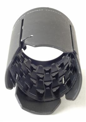
Very occasionally, screening cans are deliberately made to aid heat losses, and have fingers to contact the glass envelope. See Figure 1.19.
Input sockets
Input sockets should be kept apart from mains wiring (hum) and loudspeaker terminals (instability), but as both of these problems are caused by capacitance from the input socket to the offending connectors, screening the input socket easily cures the problem if space is limited.
An extremely useful facility on a power amplifier is to add a muting switch that applies a short circuit to the input of the power amplifier. See Figure 1.20.
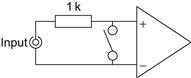
Figure 1.20 This muting switch at the input of the amplifier enables audio leads to be swapped without the necessity of switching the amplifier off.
Not only does the muting switch enable the amplifier to be plugged to different sources without having to switch it off and then on again, but it is very handy when the amplifier is being tested. The 1 kΩ resistor protects the source electronics from the short circuit.
Mechanical/safety
The purpose of the chassis is to support the components mechanically, some of which are heavy, and to enclose all the dangerous voltages, thus eliminating the risk of electric shock. The safest form of chassis for the home constructor is the totally enclosed earthed metal chassis. Placing a mains transformer in the centre of a chassis made of folded aluminium is asking for the chassis to sag. Heavy items should be placed towards the edges, where the nearby vertical section adds substantial bracing.
It’s often worth making a chassis long and slim not just because it will be more rigid, but because you stand a better chance that the throat of your pillar drill or drill stand will allow you to reach all the proposed holes than if you make a large square chassis. If a heavy item must be moved towards the centre of a chassis, a bulkhead or two can be added across the chassis to brace it, giving the further advantage of breaking the inside of the chassis into electrostatically screened compartments. This allows noisy circuitry (rectifiers and smoothing) to be placed in a “noisy” compartment, and sensitive audio in a “quiet” compartment. See Figure 1.21.
When planning the positions of the major parts, it is important that one part should not obscure electrical connections or securing screws of another unless it can be easily moved aside to gain access.
Think carefully about accessibility of fasteners. It’s time to reconsider if you can’t easily apply a spanner or nutdriver to a nut, or a screwdriver to a screw head. If there’s really no choice about nuts being inaccessible, consider securing the part with a single 3 mm plate having tapped holes in lieu of individual nuts. Conversely, consider hex head fasteners if limited axial access blocks a screwdriver but a spanner or hex key could obtain access from the side.
If the chassis is made of separate panels, how easily can each panel be removed? Wherever possible, wires should pass panels via edge slots rather than through holes to avoid those wires preventing subsequent panel removal. Failure to observe these considerations can make subsequent maintenance or modification extremely difficult. Contemporary consumer electronic design places maintainability very low on its list of priorities, but not only do you want to be able to maintain your creations, you also want to be able modify them as your knowledge improves or if better parts become available.
It is often useful to take a modular approach. If a block such as a complete heater supply including mains transformer, rectification/smoothing and regulation is made as a module on a sub-chassis, it can be conveniently built and tested outside the main chassis, then installed when ready. Printed circuit boards (PCBs) are another example of modular technique.
Components directly soldered to valve sockets and tags are known as hard-wired or point-to-point, and a less obvious power amplifier technique is to hard-wire the entire driver circuitry onto a small rectangular plate that fits over a correspondingly sized hole in the main chassis. The great advantage of this technique over mounting valve sockets directly onto the main chassis is that a complete driver redesign requiring a different number of valve bases of different types simply requires replacing the small plate. Even better, the plate can be made of perforated aluminium to assist cooling.
Bear in mind that some components can be quite large. Capacitors vary greatly in size depending on the choice of dielectric, so 100 nF can range from the size of a fingernail clipping to an entire thumb. See Figure 1.22.
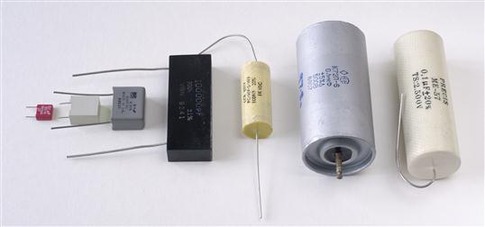
Figure 1.22 A selection of 100 n non-polarised capacitors. Left to right: 63 V polyester, 400 V polyester, 630 V polycarbonate, 200 V silvered mica, 1500 V polypropylene, 500 V polytetrafluoroethylene, 2000 V mixed dielectric.
Although we will look at electrical safety in detail later, large electrolytic smoothing capacitors should be considered during planning. When both electrical connections exit from an insulated base, there is no necessity for either terminal to be connected to the enclosing can, so the voltage on the can of the capacitor is indeterminate, but is generally near to the potential on the negative terminal. Although the can could be bonded to chassis if the negative terminal is at 0 V, this invariably causes a hum loop because of the internal capacitance between capacitor and can, so it is usually insulated from the chassis. The capacitor therefore has only a single layer of insulation between the high voltage supply and the outside world, but safety calls for either a double layer of insulation, or one layer plus an earthed metal shroud, so it is not good practice to have exposed cans outside the chassis (see later for explanation of Class I and II equipment).
Preventative maintenance means being able to see signs warning of impending failure, and catching it before it goes bang. This is one reason for having all the power valves clearly visible – if you spot a red-hot anode, you probably can get to the “on/off” switch before the fault destroys even more components. Internally, if all the components are clearly visible, you might spot a charring resistor or bulging capacitor before it destroys other components in addition to itself at the first application of power.
A rather more depressing aspect of preventative maintenance is to consider the consequences of failure of specific components. When traditional electrolytic capacitors fail, they spray soggy paper and foil from their bases. Although modern capacitors are somewhat tamer and vent in a more controlled fashion, it is a good idea to consider where any vented material might land. It would be particularly unfortunate if a failed heater supply capacitor vented a conductive spray over a perfectly innocent (powered) high voltage regulator PCB. Similarly, silicon rectifiers can sometimes fail explosively, and it would be particularly poor planning if the short-lived volcano was directly under a complex wiring loom. Although the author has not deliberately tested carbon resistors to destruction, industry wisdom is that they fail pyrotechnically.
When you work on the amplifier, you will inevitably turn it upside down, so it is helpful if the taller and heavier components can be arranged so that they allow the chassis to stand firmly without rocking, and without tipping onto the delicate valves.
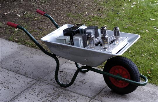
Finally, consider the likely weight of the finished amplifier, and whether you will be able to lift it. Otherwise, be prepared to need unusual methods of moving the completed amplifier. See Figure 1.23.
Acoustical
It is unusual to consider acoustical problems in a power amplifier, but the input valves are microphonic, and a flimsy chassis would not help. The author favours a rigid chassis with plenty of bracing, held together by lots of large screws, even if the result is somewhat stronger than strictly required by the supported weight.
Valves are microphonic because any relative movement between control grid and cathode alters the local electric field (volts per metre) and therefore the number of electrons reaching the anode. When the grid structure is placed closer to the cathode to increase gm, the same movement becomes proportionately greater, so valves having high gm are intrinsically more microphonic, although the more rigid frame-grid construction tames the problem. Indirectly heated valves have a rigid and firmly located cathode structure, but directly heated valves must support their heater loosely (to allow for thermal expansion), necessarily producing a cathode structure less rigid than the grid and thereby even more prone to microphony.
Pre-amplifiers may need deliberate acoustic isolation from structure-borne vibration, and anti-microphonic valve sockets with integral rubber suspension mounts used to be readily available. Nevertheless, we must take wires to that valve base, and unless the wires are flexible, they form an acoustic short circuit. A more effective way of achieving isolation borrowed from microphone mounts uses ≈1 mm-diameter knicker elastic to float a sub-chassis supporting an entire circuit in the same way that a trampoline is supported. Each anchoring point ideally requires a small rubber grommet to avoid chafing and to prevent the elastic slapping metal when the sub-chassis moves. See Figure 1.24.
The internal mechanical resonances of an indirectly heated valve are typically above 500 Hz [5], so these are the frequencies that need to be isolated. The suspended sub-chassis is effectively a 12 dB/octave low-pass filter with f−3 dB at the resonant frequency of the suspension, so if it resonated at 63 Hz (three octaves below 500 Hz), it would theoretically attenuate by 36 dB at 500 Hz. In practice, damping within the springs reduces this figure, but acoustic attenuation is generally maximised by minimising the suspension resonant frequency, given by the standard resonance equation:
![]()
Thus, deliberately adding mass (perhaps roof flashing) to the sub-chassis can improve isolation. Although the resulting suspension is likely to be stiffer than an anti-microphonic valve socket, it is still important to minimise the number of wires to the sub-chassis; use flexible wires, and dress them in slight loops to avoid them acoustically short-circuiting the suspension.
Air-borne vibration is far harder to eliminate. The ideal solution would be to enclose the circuitry within a solidly built closed box, internally lined with an acoustic absorbent such as bonded acetate fibre (BAF) or fibreglass building insulation. Unfortunately, there would then be no way for the heat to escape…
Aesthetics
Although placed last on this list, aesthetics are probably close to the forefront of your mind as you will want to be proud of the results. The finished project does not need to look like a collision between a rat’s nest and a supermarket trolley. Glowing glass is pretty, so almost all power amplifiers have their valves at the front where they can be seen. And rightly so.
Form follows function, so right-handed people generally place the most important control (volume) at the right. Symmetry is usually pleasing, so a rotary input selector switch could be placed at the left. “Retro” looks are currently very fashionable, so moving coil meters and hexagonal bakelite knobs are popular.
Sadly, blue LEDs are still popular but this aberration will doubtless pass. The author is rather fond of dual-colour LEDs (red and green) with their relative currents adjusted so as to match a valve heater’s orange glow. If the green LED is powered from the heater supply, and the red from the HT, the colour adds a useful monitoring function as well as being pretty.
Parts having specific problems and solutions
Some common parts raise specific problems that have simple solutions.
IEC mains connectors
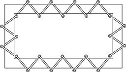
The most common (and safest) mains connector is the IEC 10A three-pin. It is far more convenient to have a fused IEC inlet than a captive mains lead and separate fuseholder, and it is often convenient to have at least one outlet. Most IEC chassis connectors are designed to be secured by M3.5 countersunk screws, but because the connectors are quite deep, fitting a nut to the back of the screw is fiddly, so a tapped hole makes sense if possible. In theory, provided the panel to be tapped is >2 mm thick, this should be fine, but IEC connectors require appreciable force to remove them, applying extra stress to the tapped threads, so 3 mm panel thickness is a more reasonable minimum.
Considering inlets, it is particularly worth planning for tapped M3.5 holes rather than clearance because:
See Figure 1.25.
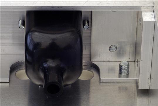
Figure 1.25 Note that this IEC inlet is secured by tapped holes in the channel, avoiding fouling the insulating boot.
Note also that the nearby transformer wires and associated grommets pass through slots cut in the channel rather than holes, thus allowing the channel to be removed with a minimum of wiring disturbance.
Considering multiple outlets, the following points make life easier later on:
• Align the outlets vertically. This uses space more efficiently on a slim chassis and allows more outlets to be fitted.
• Orient the outlets to that the live pin is closest to the chassis top plate rather than the bottom. The dangerous pin is now buried deep inside the equipment where you are far less likely to accidentally touch it during testing.
• Vertical outlets allow straight tinned copper wire bus-bars to be threaded from pin to pin – making wiring much easier and tidier.
• Mark the fixing holes after cutting the hole for the body. Once the hole for the body has been cut, an outlet can be inserted and you can mark the precise position of the holes with a scriber. Provided that the securing holes are tapped, shuttered IEC outlets will just fit between the flanges of 2″ wide ⅛″ thick aluminium channel when fitted vertically. See Figure 1.26.
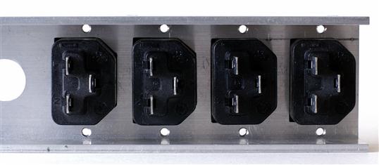
Figure 1.26 IEC mains outlets will just fit vertically between the flanges of 2″ channel provided that the aluminium is tapped to take the securing screws.
Modern mains transformers
Modern mains transformers are intended to be totally enclosed by a chassis, so they tend to be open flange or clamp mounting and therefore unsuitable for traditional exposed mounting. However, transformer lamination sizes and their fixing holes have changed little over the decades, so it is often possible to fit a shroud salvaged from an old transformer to a new one, allowing safe drop-through mounting. See Figure 1.27.
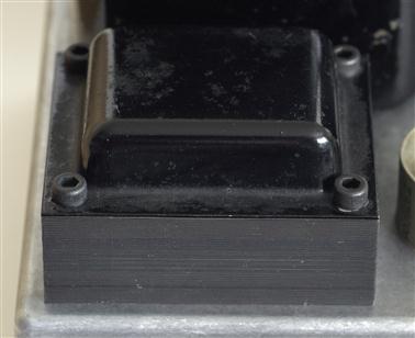
Figure 1.27 Adding a shroud salvaged from an old transformer permits safe external mounting of a modern transformer.
This new transformer originally had a steel clamp crimped round three sides, so this was gently prised away from the laminations (take care not to deform magnetic materials as it invariably degrades their magnetic properties). The dual chamber plastic bobbin didn’t initially fit into the shroud because both sides of it were fully populated with stubs for solder tags, so the unused stubs on the unwired side were carefully sawn away, allowing the shroud to fit easily. The four mounting holes on the shroud aligned perfectly with the M5 clearance holes in the laminations.
Examples
Application of the previous rules is best demonstrated by example. Bear in mind that there are many ways of skinning cats, so if you can find a better solution, use it.
Power amplifiers
Let us suppose that we want to make a mono push–pull EL84 amplifier, perhaps a Mullard 5-10 or a rebuild of a Leak TL12+.
The major items to be positioned are:
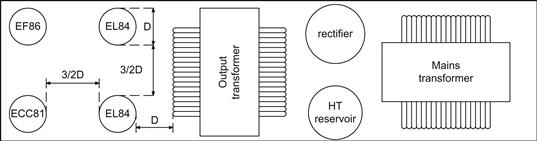
Although negative feedback reduces hum, it would be best if there were no hum induced into the output transformer from the mains transformer; we draw a line between the centres of the two transformers, and rotate them so that their coils are at 90° to each other to minimise hum. See Figure 1.28.
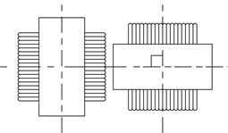
Figure 1.28 Planning a layout: A. Output transformer and mains transformer at right angles to minimise coupling.
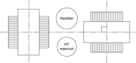
We can also reduce induced hum by moving the two transformers apart. As soon as we separate major parts, we ought to think about whether we can use the space in between them, perhaps for the reservoir capacitor. The reservoir capacitor draws current through the rectifier from the transformer in a train of 100 Hz high current pulses. See Figure 1.29.
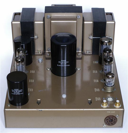
The resistance of the capacitor/rectifier/transformer wiring loop should be as low as possible, so the ideal position for the rectifier valve is adjacent to the mains transformer, with the reservoir capacitor nearby. The centre tap of the output transformer needs a low-impedance supply, so it should be close to its smoothing capacitor. If the smoothing capacitor is the traditional dual capacitor, it now makes sense for the two transformers to be moved apart just sufficiently that the rectifier and capacitor can be fitted in between with adequate room for cooling. See Figure 1.30.
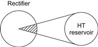
The capacitor is heated by radiation from the rectifier, but provided that there is a little separation between the two, the capacitor can cool by convection and only receives radiation proportional to the angle of arc subtended by the capacitor. See Figure 1.31.
Having chosen to fit a large electrolytic capacitor externally, we must ensure that its can is not exposed. Good quality capacitors tend to have quite thick insulating sleeves plus a phenolic insulator at their end, entirely shrouding the can, but older capacitors omit the phenolic and the sleeve may be thin or non-existent. Check first.
The output valves must be able to cool, so their centres should be separated by at least twice their envelope diameter – check their cooling factor. But they also need to be reasonably close to the output transformer, and it would be convenient if they were also reasonably close to the driver circuitry. The logical position for the output valves is thus on the side of the output transformer opposite to the rectifier, with the driver circuitry a little further beyond. The driver circuitry is now as far as possible from the mains transformer, and is partly shielded from it by the output transformer. The two transformers have their coils aligned at 90° to one another, but this can be achieved with either the coil of the mains transformer or the output transformer pointed at the driver circuitry.
If the output valves are widely spaced, even if the output transformer’s coil axis is pointed away from them, they are likely to be in the leakage field from the edges of the coil. A separation of one envelope diameter between output transformer and valve significantly reduces the localised flux leakage from the edges of the coil. This generalisation works because larger valves produce higher power and require a larger transformer. Beam valves such as KT66 having aligned grids to reduce screen grid current are particularly sensitive to magnetic fields, so even greater spacing might be desirable to avoid modulating screen grid current and causing distortion.
The valves in the driver circuitry should be separated from the output valves in order to keep them cool, and room is needed for their associated components, so moving them to the edges of the chassis allows their heater wiring to be pushed into the corners of the chassis, and coupling capacitors (which can often be quite large) can be conveniently placed between driver and output valves. We have now arrived at the final layout. See Figure 1.32.
Readers who are familiar with the Leak TL12+ will recognise that this layout is much longer and slimmer than the original Leak. The Leak layout requires longer wires, but the square chassis allowed easier access for wiring, so the reduced wiring time would have cut production costs. Further, for a given chassis area, a square chassis requires less material than a more rectangular chassis, making it cheaper.
Meters and monitoring points
Power valves are inevitably used by circuits capable of destroying them. To illustrate this point, consider the output valves in a power amplifier. They are connected to a substantial power supply via an output transformer having low DC resistance. If the valves are cathode biased, the cathode resistor will protect them in the event of a fault, but grid bias provides no protection. Grid bias inevitably requires some means of monitoring cathode current.
If you are in a “retro” mood, you will fit a handsome round black moving coil meter and a rotary switch having a black bakelite knob allowing each individual cathode current to be monitored, and if you are feeling really keen, you will add positions on the switch to allow key voltages to be monitored. The monitoring is important, so you will want to fit the meter and associated switch towards the front of the amplifier. The meter’s permanent magnet creates a stray field, so you won’t want it to be close to beam valves such as KT66, 6L6, KT88, or 6550 because it might affect DC screen grid current. The switch needs to be operated easily without obscuring the meter, and its selection and the meter must be seen simultaneously, so they have to be mounted on the same plane. If you decide to put a meter and switch on the top of the chassis, make sure there’s sufficient room to operate the switch without your fingers being burned by a nearby (hot) envelope. The best solution is that used by the McIntosh MC275 that places the meter and selector on a panel sloped at 45°.
Another possibility is to fit 4 mm chassis sockets as low voltage monitoring points, and it makes sense to put these sockets as close as possible to the voltage being monitored. However, don’t put them so close to hot valves that you burn your knuckles when unplugging the lead from your DVM. If the amplifier is push–pull, output currents must be balanced, and you will probably want to be able to connect two DVMs simultaneously, so remember to provide a 0 V test point for each DVM.
Alternatively, the traditional method was to use one meter to measure total current and another to measure imbalance current. Finding two suitable moving coil meters is tricky, but DVMs the size of a postage stamp that only need a 6 mm (¼″) mounting hole are now readily available, so they can be fitted far more easily than a moving coil meter, or you could simply provide dedicated test points for total current and imbalance.
Sympathetic power amplifier recycling
Rather than build an amplifier from scratch, you might prefer to recycle an old amplifier’s chassis and transformers, but use driver circuitry of your own design, saving an awful lot of metalwork (but very little money). If you take this approach, please do it sympathetically. Randomly gouging holes and leaving others unused looks unsightly – if it’s worth doing to please the ear, it’s worth taking a little trouble to please the eye. See Figure 1.33.
The amplifier started life as a Leak Stereo 20, but the coupling capacitors were leaky and the electrolytic capacitors had dried out, so the author decided to recycle the chassis with a simpler driver stage, using fewer valves. This left a vacant ¾″ hole, which was conveniently filled by a threaded DIN socket mounted on a small plate that was secured by the holes for the original B9A valve socket. Similarly, the holes for the original dual electrolytic capacitors were carefully enlarged for their polypropylene replacements, and a new hole was punched in front of the mains transformer for the third polypropylene capacitor. The exposed transformer links for selecting mains voltage and loudspeaker impedance were hard-wired and their connectors replaced with blank panels. The transformers were mounted on ![]() ″ phenolic board to prevent leakage flux from reaching the (steel) chassis.
″ phenolic board to prevent leakage flux from reaching the (steel) chassis.
Classic amplifiers invariably have appalling connectors, ranging from a lethal mains connector to awkward loudspeaker connectors, and this Leak Stereo 20 was no exception. Fortunately, the hole for the large three-pin Bulgin mains connector could be enlarged to take a flange mounting IEC inlet with integral fuse, and the hole for the mains outlets was enlarged to take an IEC outlet. Once unscrewed from the chassis, the tinned brass tags on the loudspeaker outlet boards were removed by squeezing their inside retaining lugs together using a pair of heavy-duty pliers, allowing three-way binding posts to be neatly fitted. A blanking grommet masked the hole for the original mains fuse, and the hole for the switch cable was opened out to take a mains switch. See Figure 1.34.

Output-transformerless (OTL) amplifiers
The significance of an OTL amplifier is that the absence of an output transformer forces the output valves to pass significant currents, and that these amplifiers need substantial global feedback, requiring unwanted voltage drops and stray capacitances to be minimised to ensure stability. The combination of these two factors requires true star earthing encompassing the entire amplifier and power supply, and this dominates mechanical design. As an example, a generic OTL headphone amplifier known at the Headwize forum as the Broskie–Cavalli–Jones (BCJ) will be considered. See Figure 1.35.
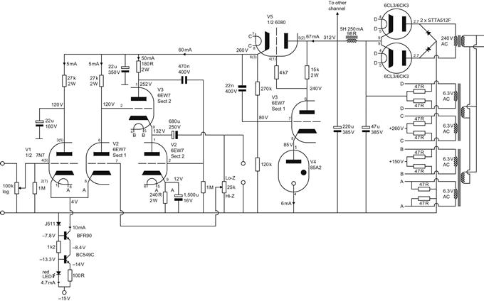
Despite initial appearances, the first two valves are not a differential pair because the first valve has its anode decoupled to ground by a capacitor. The first stage has a cathode follower with a semiconductor constant current sink as its DC load. The output of the cathode follower is direct coupled to the cathode of the common grid stage, leading the stage to be known as a cathode-coupled amplifier [6]. The cathode-coupled amplifier is direct coupled to an optimised White cathode follower output stage [7]. User-adjustable global feedback to suit the particular headphone in use is taken from the output terminals of the amplifier to the grid of the common grid stage [8].
Because optimised White cathode followers develop their correction voltage across the series combination of the intentional regulating resistor at the anode of the upper valve and the output impedance of the supply, a regulator is almost mandatory, and because the 6080 is a twin triode, a separate regulator can easily be used for each channel.
All 0 V connections from the amplifier and power supply must be brought back to the single star earth and each channel’s regulated high voltage supply must also be a star point. These two requirements enforce a circular layout and all other design considerations become secondary. See Figure 1.36.
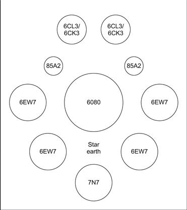
The valves must lose considerable heat, yet they are close together. The only way that this can be achieved is by mounting them on perforated sheet.
Pre-amplifiers
Pre-amplifiers present different challenges from power amplifiers. It is unusual for the power supply to be on-board, and heat is far less of an issue. Conversely, signal levels are far lower.
A pre-amplifier might traditionally have had five inputs selected by a front panel rotary switch, taking each input up to the switch using screened lead (unscreened wire would have caused hum and crosstalk problems). This was a very poor solution. Screened lead is expensive to buy and fit, yet with five inputs, this solution only ever used a fifth of the wire at any given time. The place for the input selector switch is on a bracket at the back of the pre-amplifier, sufficiently close to the input sockets that unscreened wire from each socket to switch contacts does not pick up interference.
The output of the selector switch feeds the volume control, so the obvious position is nearby, but it is often best positioned diagonally opposite because this minimises lead length (and therefore shunt capacitance) from the output of the control. See Figure 1.37.
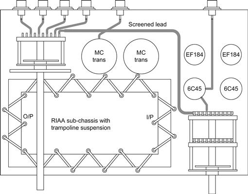
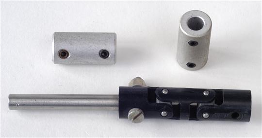
The layout assumes a right-handed operator, so you might want to mirror it if you are belligerently left-handed. The selector switch is mounted at the back left, and extended to the front with a coupling and a length of 6 mm or ¼″ shaft as appropriate (13″ lengths of stainless or silver steel rod are cheap at engineering suppliers). If necessary, a coupling could be bodged from a short length of motorcycle fuel hose and associated Jubilee clamps, but a proper coupler is better. See Figure 1.38.
This pre-amplifier has a buffer between the volume control and its output, so this circuitry is logically best positioned at the back right, forcing the volume control towards the front of the chassis. This layout also assumes an RIAA stage using input transformers, and since they generally have flying leads, it makes sense to position them between the input sockets and the first gain stage, because it allows their (flexible) leads to link the (floating) sub-chassis to the connectors on the (fixed) main chassis. The RIAA stage is suspended on knicker elastic, and the necessary gap all around its sub-chassis allows cooling air past its valves. The stage runs from right to left, so its output is close to the selector switch. The output of the selector switch to the volume control is a comparatively long run, so screened lead is necessary. An electrostatic screen could be added between the RIAA stage and the volume control, but this is probably unnecessary.
Umbilical leads
Since a pre-amplifier almost invariably has a remote supply, it needs an umbilical lead to connect the two together. To allow either item to be moved, the umbilical cable needs to be unpluggable. The obvious solution is to provide a connector at each end of the umbilical lead. Once you have seen the cost of multi-pole connectors, you will quickly decide that a connector is needed at only one end of the lead. The problem is to decide which end of the lead should have the connector.
It makes better sense to make the lead part of the pre-amplifier rather than the power supply. The reason for this is that a pre-amplifier tends to be designed for a specific application, perhaps to match a particular cartridge in a particular turntable, and to drive particular power amplifiers. That being the case, its proposed physical positioning is also known, so required lead lengths are also known. The previous argument also applies to its audio leads, so why not also hard-wire the outputs, rather than adding expensive and unnecessary connectors?
Personality
A typical power supply provides a high voltage supply, one, or more heater supplies, and perhaps some means of remote power switching. All pre-amplifiers need some, or all, of these facilities, so it would be very useful if a given power supply could be used by any pre-amplifier. A pre-amplifier could then be quickly and easily replaced without having to modify the power supply. One obvious consequence of this approach is that the power supply’s multi-pole connector should be chosen so as to leave pins for future expansion and that extra connectors for future pre-amplifiers must be readily available at a later date. Thus, if you spot a bargain connector, buy as many cable plugs to fit the chassis socket as you think you will need for future pre-amplifiers. (Remember that the power supply’s chassis connector must be a socket to make it impossible for your fingers to contact potentially live pins.)
Pre-amplifiers often need elevated heater supplies to keep Vhk within acceptable limits in circuits such as cathode followers or cascode where a cathode could easily be at 200 V. The required elevating voltages are determined purely by the pre-amplifier, so any circuit for elevating the heater supplies should be within the pre-amplifier chassis, not the power supply. In this way, the power supply’s personality is determined purely by the pre-amplifier plugged into it, and it remains universal. Thus, all individual supplies within the power supply should float from the chassis, so that their connections to chassis and to one another are determined purely by the associated pre-amplifier.
Mains/chassis earth has to be carried from the power supply to the pre-amplifier, and it is vital that this connection is reliable and low resistance. If at all possible, use more than one pin on the connector to carry this connection – this might mean that you need a larger connector with more pins, but it’s safer and less likely to hum. We want a low-resistance bond between the two chassis, so that implies a good cross-section of copper conductor in the umbilical lead. The best way of achieving this is to use an umbilical cable having a braided screen, and use the screen as the earth bond connector. If you make up your own cables, use two, or perhaps even three, layers of screens because this will not only ensure that there are no gaps in the composite screen but it constitutes a robust cable having a low earth resistance. By the time your umbilical has all this screening, plus a protective nylon braid over the top, it will be quite thick, so make sure that your chosen connector has a large enough cable entry to accommodate and clamp such a cable securely.
Power supplies
Fortunately, power supply planning is much simpler than that required for amplifiers. The function of a power supply is to take AC mains, rectify it and deliver clean DC to another point, so it makes sense to lay a power supply out so that one end is deemed to be “dirty” (incoming AC mains, AC outlets, and rectification) and the far end “clean” (regulators, DC outlets).
Regulator positioning
The ideal position for a regulator is adjacent to the load because this minimises unwanted voltage drops, yet there can be powerful arguments against this positioning, particularly when the load is a pre-amplifier:
• Regulators are inevitably hot, and pre-amplifiers should stay cool.
• The raw input to a regulator is likely to be noisy.
• High voltage regulators using valves require heater wiring, usually AC, and therefore noisy. Obviously, semiconductor regulators do not suffer from this problem, and can be more easily placed adjacent to the load.
• Valve heaters draw significant current, causing a voltage drop down the umbilical cable. However, a remote heater regulator can circumvent this problem because its output voltage can be adjusted to compensate whilst measuring the voltage at the valve pins.
Once these considerations have been taken together, the outcome is that heater regulators and high voltage regulators using valves are invariably within the remote power supply, and only semiconductor high voltage regulators can be in the ideal position adjacent to their load.
Professional power supplies often permit remote sensing, also known as four-wire connection, so that each output terminal has a “sense” terminal associated with it that is connected to the (remote) load, thus automatically compensating for cable resistance. Although this technique requires extra pins on the connector and wires in the umbilical lead, the extra leads do not pass significant current. See Figure 1.39.
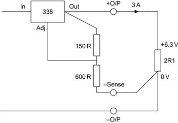
Note that the three-terminal LM338 is unable to accommodate true four-wire sensing, so only the bottom of the divider chain can be returned to the load. A more sophisticated supply would also return the upper end of the divider chain to the load.
Regulators and heatsinks
Power supplies may need TO-3 style regulators or series pass transistors to be fitted to the chassis. You don’t need to measure and mark out all the holes precisely – simply use the mica washer from an insulating kit as a template to mark out the holes. If you are using power transistors, they will be hot, so calculate how many watts of heat must be dissipated, assume a heatsink temperature of 50°C (30°C above ambient), and calculate whether you need a dedicated heatsink, or whether the chassis will do:
![]()
As an example, we might have an LM338 heater regulator passing 3 A, with a drop of 6 V across it, corresponding to 18 W of dissipation. As a very rough approximation, if a reasonably large chassis has sides made of 2″×1″×⅛″ thick channel, at any given point, the channel has a thermal resistance of ≈1°C/W. Thus, mounting the regulator on the channel would keep the temperature rise to ≈18°C, resulting in a local chassis temperature of ≈38°C, which is acceptable. However, if two such regulators were nearby, the chassis temperature could easily exceed 50°C, so it might be worth either fitting an additional finned heatsink or separating the heat sources by a few inches (50–70 mm).
References
1. Gayford M, ed. Microphone Engineering Handbook. Focal Press 1994; ISBN 0-7506-1199-5.
2. Welsby VG. The Theory and Design of Inductance Coils 2nd edn. Macdonald 1960.
3. “Type KT66”, Osram Valve Technical Publication TP3. GEC (February 1949).
4. “Components Group Mobile Exhibition”, Brimar Valves (November 1959).
5. Mullard Technical Communication (November 1962). Available at: http://www.thevalvepage.com/valvetek/microph/microph.htm.
6. Typical Oscilloscope Circuitry, revised edition. Tektronix (1966).
7. J. Broskie, The White cathode follower. Tube CAD Journal (October 1999). Available at: http://www.tubecad.com/october99/page4.html.
8. A post by Alex Cavalli on page 5 of the “Building the Morgan Jones” DIY forum thread. Available at: http://headwize2.powerpill.org/.
Recommended further reading
1. Ott HW. Noise Reduction Techniques In Electronic Systems 2nd edn. Wiley 1988; ISBN 0-471-85068-3.
Slightly misnamed (its main focus is interference reduction), this was one of the first books to formally cover EMC and is still one of the best.
2. Goedbloed J. Electromagnetic Compatibility (Phillips Research Laboratories) Prentice-Hall 1990; ISBN 0-13-249293-8.
Given that Philips was a component manufacturer at the time, this excellent book contains plenty of theoretical considerations for component design and usage backed up by measurements.
3. Zepler EE. The Technique of Radio Design Chapman & Hall 1943.
Although general, seventy pages over three chapters (“The Principles of Screening”, “Undesired Feedback”, and “Hum, Spurious Beats”) tackle valve-specific problems and make this little book well worth searching out.
4. M.G. Scroggie, Foundations of wireless (and Electronics), 7th edn. Iliffe.
Accessibly written for the amateur, any edition of this book is worth reading for useful radio frequency hints and tips that can be subverted for audio use.
5. Radio Society of Great Britain, Radio Communication Handbook, 5th edn. Radio Society of Great Britain (1976), ISBN 0 900612 58 4.
This was the last edition to cover valves in any detail and covers more material in greater depth than Scroggie but does not quite have the coherence of a single author.
American Radio Relay League, The Radio Amateur’s Handbook, many editions.
The author has the 1947 25th edition and 1958 35th edition (however did they find the time to revise it annually?). This is the US equivalent to the UK ham radio book and is arguably slightly better, containing many informative photographs showing good layout. Any edition should be worthwhile, although fundamentals are better covered in the 1947 edition than the 1958 edition, presumably due to pressure of space caused by new developments.
*An exclusion zone is defined as the circle diameter coaxial with the valve where nothing, including other exclusion zones, may enter.