Chapter 6
Cisco’s Internetworking Operating System (IOS)
THE FOLLOWING ICND1 EXAM TOPICS ARE COVERED IN THIS CHAPTER:
- ✓ 2.0 LAN Switching Technologies
- ✓ 2.3 Troubleshoot interface and cable issues (collisions, errors, duplex, speed)
- ✓ 5.0 Infrastructure Management
- ✓ 5.3 Configure and verify initial device configuration
- ✓ 5.4 Configure, verify, and troubleshoot basic device hardening
- ✓ 5.4.a Local authentication
- ✓ 5.4.b Secure password
- ✓ 5.4.c Access to device
- 5.4.c. (i) Voice
- 5.4.c. (ii) Video
- ✓ 5.4.c. (iii) Data
- ✓ 5.4.d Source address Telnet/SSH
- ✓ 5.4.e Login banner
- ✓ 5.6 Use Cisco IOS tools to troubleshoot and resolve problems
- 5.6.a Ping and traceroute with extended option
- 5.6.b Terminal monitor
- 5.6.c Log events
 It’s time to introduce you to the Cisco Internetwork Operating System (IOS). The IOS is what runs Cisco routers as well as Cisco’s switches, and it’s also what we use to configure these devices.
So that’s what you’re going to learn about in this chapter. I’m going to show you how to configure a Cisco IOS device using the Cisco IOS command-line interface (CLI). Once proficient with this interface, you’ll be able to configure hostnames, banners, passwords, and more as well as troubleshoot skillfully using the Cisco IOS.
We’ll also begin the journey to mastering the basics of router and switch configurations plus command verifications in this chapter.
I’ll start with a basic IOS switch to begin building the network we’ll use throughout this book for configuration examples. Don’t forget—I’ll be using both switches and routers throughout this chapter, and we configure these devices pretty much the same way. Things diverge when we get to the interfaces where the differences between the two become key, so pay attention closely when we get to that point!
Just as it was with preceding chapters, the fundamentals presented in this chapter are important building blocks to have solidly in place before moving on to the more advanced material coming up in the next ones.
The IOS User Interface
The Cisco Internetwork Operating System (IOS) is the kernel of Cisco routers as well as all current Catalyst switches. In case you didn’t know, a kernel is the elemental, indispensable part of an operating system that allocates resources and manages tasks like low-level hardware interfaces and security.
Coming up, I’ll show you the Cisco IOS and how to configure a Cisco switch using the command-line interface (CLI). By using the CLI, we can provide access to a Cisco device and provide voice, video, and data service. . . . The configurations you’ll see in this chapter are exactly the same as they are on a Cisco router.
Cisco IOS
The Cisco IOS is a proprietary kernel that provides routing, switching, internetworking, and telecommunications features. The first IOS was written by William Yeager in 1986 and enabled networked applications. It runs on most Cisco routers as well as a growing number of Cisco Catalyst switches, like the Catalyst 2960 and 3560 series switches used in this book. And it’s an essential for the Cisco exam objectives!
Here’s a short list of some important things that the Cisco router IOS software is responsible for:
- Carrying network protocols and functions
- Connecting high-speed traffic between devices
- Adding security to control access and stopping unauthorized network use
- Providing scalability for ease of network growth and redundancy
- Supplying network reliability for connecting to network resources
You can access the Cisco IOS through the console port of a router or switch, from a modem into the auxiliary (or aux) port on a router, or even through Telnet and Secure Shell (SSH). Access to the IOS command line is called an EXEC session.
Connecting to a Cisco IOS Device
We connect to a Cisco device to configure it, verify its configuration, and check statistics, and although there are different approaches to this, the first place you would usually connect to is the console port. The console port is usually an RJ45, 8-pin modular connection located at the back of the device, and there may or may not be a password set on it by default.
You can also connect to a Cisco router through an auxiliary port, which is really the same thing as a console port, so it follows that you can use it as one. The main difference with an auxiliary port is that it also allows you to configure modem commands so that a modem can be connected to the router. This is a cool feature because it lets you dial up a remote router and attach to the auxiliary port if the router is down and you need to configure it remotely, out-of-band. One of the differences between Cisco routers and switches is that switches do not have an auxiliary port.
The third way to connect to a Cisco device is in-band, through the program Telnet or Secure Shell (SSH). In-band means configuring the device via the network, the opposite of out-of-band. We covered Telnet and SSH in Chapter 3, “Introduction to TCP/IP,” and in this chapter, I’ll show you how to configure access to both of these protocols on a Cisco device.
Figure 6.1 shows an illustration of a Cisco 2960 switch. Really focus in on all the different kinds of interfaces and connections! On the right side is the 10/100/1000 uplink. You can use either the UTP port or the fiber port, but not both at the same time.

Figure 6.1 A Cisco 2960 switch
The 3560 switch I’ll be using in this book looks a lot like the 2960, but it can perform layer 3 switching, unlike the 2960, which is limited to only layer 2 functions.
I also want to take a moment and tell you about the 2800 series router because that’s the router series I’ll be using in this book. This router is known as an Integrated Services Router (ISR) and Cisco has updated it to the 2900 series, but I still have plenty of 2800 series routers in my production networks. Figure 6.2 shows a new 1900 series router. The new ISR series of routers are nice; they are so named because many services, like security, are built into them. The ISR series router is a modular device, much faster and a lot sleeker than the older 2600 series routers, and it’s elegantly designed to support a broad new range of interface options. The new ISR series router can offer multiple serial interfaces, which can be used for connecting a T1 using a serial V.35 WAN connection. And multiple Fast Ethernet or Gigabit Ethernet ports can be used on the router, depending on the model. This router also has one console via an RJ45 connector and another through the USB port. There is also an auxiliary connection to allow a console connection via a remote modem.
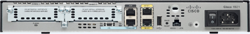
Figure 6.2 A new Cisco 1900 router
You need to keep in mind that for the most part, you get some serious bang for your buck with the 2800/2900—unless you start adding a bunch of interfaces to it. You’ve got to pony up for each one of those little beauties, so this can really start to add up and fast!
A couple of other series of routers that will set you back a lot less than the 2800 series are the 1800/1900s, so look into these routers if you want a less-expensive alternative to the 2800/2900 but still want to run the same IOS.
So even though I’m going to be using mostly 2800 series routers and 2960/3560 switches throughout this book to demonstrate examples of IOS configurations, I want to point out that the particular router model you use to practice for the Cisco exam isn’t really important. The switch types are, though—you definitely need a couple 2960 switches as well as a 3560 switch if you want to measure up to the exam objectives!
Bringing Up a Switch
When you first bring up a Cisco IOS device, it will run a power-on self-test—a POST. Upon passing that, the machine will look for and then load the Cisco IOS from flash memory if an IOS file is present, then expand it into RAM. As you probably know, flash memory is electronically erasable programmable read-only memory—an EEPROM. The next step is for the IOS to locate and load a valid configuration known as the startup-config that will be stored in nonvolatile RAM (NVRAM).
Once the IOS is loaded and up and running, the startup-config will be copied from NVRAM into RAM and from then on referred to as the running-config.
But if a valid startup-config isn’t found in NVRAM, your switch will enter setup mode, giving you a step-by-step dialog to help configure some basic parameters on it.
You can also enter setup mode at any time from the command line by typing the command setup from privileged mode, which I’ll get to in a minute. Setup mode only covers some basic commands and generally isn’t really all that helpful. Here’s an example:
Would you like to enter the initial configuration dialog? [yes/no]: y

At any point you may enter a question mark '?' for help.
Use ctrl-c to abort configuration dialog at any prompt.
Default settings are in square brackets '[]'.

Basic management setup configures only enough connectivity
for management of the system, extended setup will ask you
to configure each interface on the system

Would you like to enter basic management setup? [yes/no]: y
Configuring global parameters:

  Enter host name [Switch]: Ctrl+C
Configuration aborted, no changes made.I highly recommend going through setup mode once, then never again because you should always use the CLI instead!
Command-Line Interface (CLI)
I sometimes refer to the CLI as “cash line interface” because the ability to create advanced configurations on Cisco routers and switches using the CLI will earn you some decent cash!
Entering the CLI
After the interface status messages appear and you press Enter, the Switch> prompt will pop up. This is called user exec mode, or user mode for short, and although it’s mostly used to view statistics, it is also a stepping stone along the way to logging in to privileged exec mode, called privileged mode for short.
You can view and change the configuration of a Cisco router only while in privileged mode, and you enter it via the enable command like this:
Switch>enable
Switch#
The Switch# prompt signals you’re in privileged mode where you can both view and change the switch configuration. You can go back from privileged mode into user mode by using the disable command:
Switch#disable
Switch>
You can type logout from either mode to exit the console:
Switch>logout
Switch con0 is now available
Press RETURN to get started.
Next, I’ll show how to perform some basic administrative configurations.
Overview of Router Modes
To configure from a CLI, you can make global changes to the router by typing configure terminal or just config t. This will get you into global configuration mode where you can make changes to the running-config. Commands run from global configuration mode are predictably referred to as global commands, and they are typically set only once and affect the entire router.
Type config from the privileged-mode prompt and then press Enter to opt for the default of terminal like this:
Switch#config
Configuring from terminal, memory, or network [terminal]? [press enter]
Enter configuration commands, one per line.  End with CNTL/Z.
Switch(config)#
At this point, you make changes that affect the router as a whole (globally), hence the term global configuration mode. For instance, to change the running-config—the current configuration running in dynamic RAM (DRAM)—use the configure terminal command, as I just demonstrated.
CLI Prompts
Let’s explore the different prompts you’ll encounter when configuring a switch or router now, because knowing them well will really help you orient yourself and recognize exactly where you are at any given time while in configuration mode. I’m going to demonstrate some of the prompts used on a Cisco switch and cover the various terms used along the way. Make sure you’re very familiar with them, and always check your prompts before making any changes to a router’s configuration!
We’re not going to venture into every last obscure command prompt you could potentially come across in the configuration mode world because that would get us deep into territory that’s beyond the scope of this book. Instead, I’m going to focus on the prompts you absolutely must know to pass the exam plus the very handy and seriously vital ones you’ll need and use the most in real-life networking—the cream of the crop.
Interfaces
To make changes to an interface, you use the interface command from global configuration mode:
Switch(config)#interface ?
  Async              Async interface
  BVI                Bridge-Group Virtual Interface
  CTunnel            CTunnel interface
  Dialer             Dialer interface
  FastEthernet       FastEthernet IEEE 802.3
  Filter             Filter interface
  Filtergroup        Filter Group interface
  GigabitEthernet    GigabitEthernet IEEE 802.3z
  Group-Async        Async Group interface
  Lex                Lex interface
  Loopback           Loopback interface
  Null               Null interface
  Port-channel       Ethernet Channel of interfaces
  Portgroup          Portgroup interface
  Pos-channel        POS Channel of interfaces
  Tunnel             Tunnel interface
  Vif                PGM Multicast Host interface
  Virtual-Template   Virtual Template interface
  Virtual-TokenRing  Virtual TokenRing
  Vlan               Catalyst Vlans
  fcpa               Fiber Channel
  range              interface range command
Switch(config)#interface fastEthernet 0/1
Switch(config-if)#)
Did you notice that the prompt changed to Switch(config-if)#? This tells you that you’re in interface configuration mode. And wouldn’t it be nice if the prompt also gave you an indication of what interface you were configuring? Well, at least for now we’ll have to live without the prompt information, because it doesn’t. But it should already be clear to you that you really need to pay attention when configuring an IOS device!
Line Commands
To configure user-mode passwords, use the line command. The prompt then becomes Switch(config-line)#:
Switch(config)#line ?
  <0-16>   First Line number
  console  Primary terminal line
  vty      Virtual terminal
Switch(config)#line console 0
Switch(config-line)#
The line console 0 command is a global command, and sometimes you’ll also hear people refer to global commands as major commands. In this example, any command typed from the (config-line) prompt is known as a subcommand.
Access List Configurations
To configure a standard named access list, you’ll need to get to the prompt Switch(config-std-nacl)#:
Switch#config t
Switch(config)#ip access-list standard Todd
Switch(config-std-nacl)#
What you see here is a typical basic standard ACL prompt. There are various ways to configure access lists, and the prompts are only slightly different from this particular example.
Routing Protocol Configurations
I need to point out that we don’t use routing or router protocols on 2960 switches, but we can and will use them on my 3560 switches. Here is an example of configuring routing on a layer 3 switch:
Switch(config)#router rip
IP routing not enabled
Switch(config)#ip routing
Switch(config)#router rip
Switch(config-router)#
Did you notice that the prompt changed to Switch(config-router)#? To make sure you achieve the objectives specific to the Cisco exam and this book, I’ll configure static routing, RIPv2, and RIPng. And don’t worry—I’ll explain all of these in detail soon, in Chapter 9, “IP Routing,” and Chapter 14, “Internet Protocol Version 6 (IPv6)”!
Defining Router Terms
Table 6.1 defines some of the terms I’ve used so far.
Table 6.1 Router terms
| Mode | Definition |
| User exec mode | Limited to basic monitoring commands |
| Privileged exec mode | Provides access to all other router commands |
| Global configuration mode | Commands that affect the entire system |
| Specific configuration modes | Commands that affect interfaces/processes only |
| Setup mode | Interactive configuration dialog |
Editing and Help Features
The Cisco advanced editing features can also help you configure your router. If you type in a question mark (?) at any prompt, you’ll be given a list of all the commands available from that prompt:
Switch#?
Exec commands:
  access-enable    Create a temporary Access-List entry
  access-template  Create a temporary Access-List entry
  archive          manage archive files
  cd               Change current directory
  clear            Reset functions
  clock            Manage the system clock
  cns              CNS agents
  configure        Enter configuration mode
  connect          Open a terminal connection
  copy             Copy from one file to another
  debug            Debugging functions (see also 'undebug')
  delete           Delete a file
  diagnostic       Diagnostic commands
  dir              List files on a filesystem
  disable          Turn off privileged commands
  disconnect       Disconnect an existing network connection
  dot1x            IEEE 802.1X Exec Commands
  enable           Turn on privileged commands
  eou              EAPoUDP
  erase            Erase a filesystem
  exit             Exit from the EXEC
 ––More–– ?
Press RETURN for another line, SPACE for another page, anything else to quit
And if this is not enough information for you, you can press the spacebar to get another whole page of information, or you can press Enter to go one command at a time. You can also press Q, or any other key for that matter, to quit and return to the prompt. Notice that I typed a question mark (?) at the more prompt and it told me what my options were from that prompt.
Here’s a shortcut: To find commands that start with a certain letter, use the letter and the question mark with no space between them, like this:
Switch#c?
cd       clear  clock  cns  configure
connect  copy
Switch#c
Okay, see that? By typing c?, I got a response listing all the commands that start with c. Also notice that the Switch#c prompt reappears after the list of commands is displayed. This can be really helpful when you happen to be working with long commands but you’re short on patience and still need the next possible one. It would get old fast if you actually had to retype the entire command every time you used a question mark!
So with that, let’s find the next command in a string by typing the first command and then a question mark:
Switch#clock ?
  set  Set the time and date

Switch#clock set ?
  hh:mm:ss  Current Time

Switch#clock set 2:34 ?
% Unrecognized command

Switch#clock set 2:34:01 ?
  <1-31>  Day of the month
  MONTH   Month of the year

Switch#clock set 2:34:01 21 july ?
  <1993-2035>  Year

Switch#clock set 2:34:01 21 august 2013
Switch#
00:19:45: %SYS-6-CLOCKUPDATE: System clock has been updated from 00:19:45
UTC Mon Mar 1 1993 to 02:34:01 UTC Wed Aug 21 2013, configured from console
by console.
I entered the clock ? command and got a list of the next possible parameters plus what they do. Make note of the fact that you can just keep typing a command, a space, and then a question mark until <cr> (carriage return) is your only option left.
And if you’re typing commands and receive
Switch#clock set 11:15:11
% Incomplete command.
no worries—that’s only telling you that the command string simply isn’t complete quite yet. All you need to do is to press the up arrow key to redisplay the last command entered and then continue with the command by using your question mark.
But if you get the error
Switch(config)#access-list 100 permit host 1.1.1.1 host 2.2.2.2
                                      ^
% Invalid input detected at '^' marker.
all is not well because it means you actually have entered a command incorrectly. See that little caret—the ^? It’s a very helpful tool that marks the exact point where you blew it and made a mess.
Here’s another example of when you’ll see that caret:
Switch#sh fastethernet 0/0
            ^
% Invalid input detected at '^' marker.
This command looks right, but be careful! The problem is that the full command is show interface fastethernet 0/0.
Now if you receive the error
Switch#sh cl
% Ambiguous command:  "sh cl"
you’re being told that there are multiple commands that begin with the string you entered and it’s not unique. Use the question mark to find the exact command you need:
Switch#sh cl?
class-map  clock  cluster
Case in point: There are three commands that start with show cl.
Table 6.2 lists the enhanced editing commands available on a Cisco router.
Table 6.2 Enhanced editing commands
| Command | Meaning |
| Ctrl+A | Moves your cursor to the beginning of the line |
| Ctrl+E | Moves your cursor to the end of the line |
| Esc+B | Moves back one word |
| Ctrl+B | Moves back one character |
| Ctrl+F | Moves forward one character |
| Esc+F | Moves forward one word |
| Ctrl+D | Deletes a single character |
| Backspace | Deletes a single character |
| Ctrl+R | Redisplays a line |
| Ctrl+U | Erases a line |
| Ctrl+W | Erases a word |
| Ctrl+Z | Ends configuration mode and returns to EXEC |
| Tab | Finishes typing a command for you |
Another really cool editing feature you need to know about is the automatic scrolling of long lines. In the following example, the command I typed reached the right margin and automatically moved 11 spaces to the left. How do I know this? Because the dollar sign [$] is telling me that the line has been scrolled to the left:
Switch#config t
Switch(config)#$ 100 permit ip host 192.168.10.1 192.168.10.0 0.0.0.255
You can review the router-command history with the commands shown in Table 6.3.
Table 6.3 IOS-command history
| Command | Meaning |
| Ctrl+P or up arrow | Shows last command entered |
| Ctrl+N or down arrow | Shows previous commands entered |
show history |
Shows last 20 commands entered by default |
show terminal |
Shows terminal configurations and history buffer size |
terminal history size |
Changes buffer size (max 256) |
The following example demonstrates the show history command as well as how to change the history’s size. It also shows how to verify the history with the show terminal command. First, use the show history command, which will allow you to see the last 20 commands that were entered on the router (even though my particular router reveals only 10 commands because that’s all I’ve entered since rebooting it). Check it out:
Switch#sh history
  sh fastethernet 0/0
  sh ru
  sh cl
  config t
  sh history
  sh flash
  sh running-config
  sh startup-config
  sh ver
  sh history
Okay—now, we’ll use the show terminal command to verify the terminal history size:
Switch#sh terminal
Line 0, Location: "", Type: ""
Length: 24 lines, Width: 80 columns
Baud rate (TX/RX) is 9600/9600, no parity, 2 stopbits, 8 databits
Status: PSI Enabled, Ready, Active, Ctrl-c Enabled, Automore On
  0x40000
Capabilities: none
Modem state: Ready
[output cut]
Modem type is unknown.
Session limit is not set.
Time since activation: 00:17:22
Editing is enabled.
History is enabled, history size is 10.
DNS resolution in show commands is enabled
Full user help is disabled
Allowed input transports are none.
Allowed output transports are telnet.
Preferred transport is telnet.
No output characters are padded
No special data dispatching charactersAdministrative Configurations
Even though the following sections aren’t critical to making a router or switch work on a network, they’re still really important. I’m going to guide you through configuring specific commands that are particularly helpful when administering your network.
You can configure the following administrative functions on a router and switch:
- Hostnames
- Banners
- Passwords
- Interface descriptions
Remember, none of these will make your routers or switches work better or faster, but trust me, your life will be a whole lot better if you just take the time to set these configurations on each of your network devices. This is because doing so makes troubleshooting and maintaining your network a great deal easier—seriously! In this next section, I’ll be demonstrating commands on a Cisco switch, but understand that these commands are used in the exact same way on a Cisco router.
Hostnames
We use the hostname command to set the identity of the router and switch. This is only locally significant, meaning it doesn’t affect how the router or switch performs name lookups or how the device actually works on the internetwork. But the hostname is still important in routes because it’s often used for authentication in many wide area networks (WANs). Here’s an example:
Switch#config t
Switch(config)#hostname Todd
Todd(config)#hostname Chicago
Chicago(config)#hostname Todd
Todd(config)#
I know it’s pretty tempting to configure the hostname after your own name, but it’s usually a much better idea to name the device something that relates to its physical location. A name that maps to where the device lives will make finding it a whole lot easier, which among other things, confirms that you’re actually configuring the correct device. Even though it seems like I’m completely ditching my own advice by naming mine Todd, I’m not, because this particular device really does live in “Todd’s” office. Its name perfectly maps to where it is, so it won’t be confused with those in the other networks I work with!
Banners
A very good reason for having a banner is to give any and all who dare attempt to telnet or sneak into your internetwork a little security notice. And they’re very cool because you can create and customize them so that they’ll greet anyone who shows up on the router with exactly the information you want them to have!
Here are the three types of banners you need to be sure you’re familiar with:
- Exec process creation banner
- Login banner
- Message of the day banner
And you can see them all illustrated in the following code:
Todd(config)#banner ?
  LINE            c banner-text c, where 'c' is a delimiting character
  exec            Set EXEC process creation banner
  incoming        Set incoming terminal line banner
  login           Set login banner
  motd            Set Message of the Day banner
  prompt-timeout  Set Message for login authentication timeout
  slip-ppp        Set Message for SLIP/PPP
Message of the day (MOTD) banners are the most widely used banners because they give a message to anyone connecting to the router via Telnet or an auxiliary port or even through a console port as seen here:
Todd(config)#banner motd ?
LINE c banner-text c, where 'c' is a delimiting character
Todd(config)#banner motd #
Enter TEXT message. End with the character '#'.
$ Acme.com network, then you must disconnect immediately.
#
Todd(config)#^Z (Press the control key + z keys to return to privileged mode)
Todd#exit
con0 is now available
Press RETURN to get started.
If you are not authorized to be in Acme.com network, then you
must disconnect immediately.
Todd#
This MOTD banner essentially tells anyone connecting to the device to get lost if they’re not on the guest list. The part to focus upon here is the delimiting character, which is what informs the router the message is done. Clearly, you can use any character you want for it except for the delimiting character in the message itself. Once the message is complete, press Enter, then the delimiting character, and then press Enter again. Everything will still work if you don’t follow this routine unless you have more than one banner. If that’s the case, make sure you do follow it or your banners will all be combined into one message and put on a single line!
You can set a banner on one line like this:
Todd(config)#banner motd x Unauthorized access prohibited! xLet’s take a minute to go into more detail about the other two types of banners I mentioned:
Exec banner You can configure a line-activation (exec) banner to be displayed when EXEC processes such as a line activation or an incoming connection to a VTY line have been created. Simply initiating a user exec session through a console port will activate the exec banner.
Login banner You can configure a login banner for display on all connected terminals. It will show up after the MOTD banner but before the login prompts. This login banner can’t be disabled on a per-line basis, so to globally disable it you’ve got to delete it with the no banner login command.
Here’s what a login banner output looks like:
!
banner login ^C
——————————————————————————————————————————————————————————————————————————–
Cisco Router and Security Device Manager (SDM) is installed on this device.
This feature requires the one-time use of the username "cisco"
with the password "cisco". The default username and password
have a privilege level of 15.
Please change these publicly known initial credentials using
SDM or the IOS CLI.
Here are the Cisco IOS commands.
username <myuser>  privilege 15 secret 0 <mypassword>
no username cisco
Replace <myuser> and <mypassword> with the username and
password you want to use.
For more information about SDM please follow the instructions
in the QUICK START GUIDE for your router or go to http://www.cisco.com/go/sdm
————————————————————————————————————————————————————————————————————————————–
^C
!
The previous login banner should look pretty familiar to anyone who’s ever logged into an ISR router because it’s the banner Cisco has in the default configuration for its ISR routers.
Setting Passwords
There are five passwords you’ll need to secure your Cisco routers: console, auxiliary, telnet/SSH (VTY), enable password, and enable secret. The enable secret and enable password are the ones used to set the password for securing privileged mode. Once the enable commands are set, users will be prompted for a password. The other three are used to configure a password when user mode is accessed through the console port, through the auxiliary port, or via Telnet.
Let’s take a look at each of these now.
Enable Passwords
You set the enable passwords from global configuration mode like this:
Todd(config)#enable ?
 last-resort Define enable action if no TACACS servers
             respond
 password    Assign the privileged level password
 secret      Assign the privileged level secret
 use-tacacs  Use TACACS to check enable passwords
The following list describes the enable password parameters:
last-resort This allows you to still enter the device if you set up authentication through a TACACS server and it’s not available. It won’t be used if the TACACS server is working.
password This sets the enable password on older, pre-10.3 systems and isn’t ever used if an enable secret is set.
secret The newer, encrypted password that overrides the enable password if it has been set.
use-tacacs This tells the router or switch to authenticate through a TACACS server. It comes in really handy when you have lots of routers because changing the password on a multitude of them can be insanely tedious. It’s much easier to simply go through the TACACS server and change the password only once!
Here’s an example that shows how to set the enable passwords:
Todd(config)#enable secret todd
Todd(config)#enable password todd
The enable password you have chosen is the same as your
  enable secret. This is not recommended. Re-enter the
  enable password.
If you try to set the enable secret and enable passwords the same, the device will give you a polite warning to change the second password. Make a note to yourself that if there aren’t any old legacy routers involved, you don’t even bother to use the enable password!
User-mode passwords are assigned via the line command like this:
Todd(config)#line ?
  <0-16>   First Line number
  console  Primary terminal line
  vty      Virtual terminal
And these two lines are especially important for the exam objectives:
console Sets a console user-mode password.
vty Sets a Telnet password on the device. If this password isn’t set, then by default, Telnet can’t be used.
To configure user-mode passwords, choose the line you want and configure it using the login command to make the switch prompt for authentication. Let’s focus in on the configuration of individual lines now.
Console Password
We set the console password with the line console 0 command, but look at what happened when I tried to type line console ? from the (config-line)# prompt—I received an error! Here’s the example:
Todd(config-line)#line console ?
% Unrecognized command
Todd(config-line)#exit
Todd(config)#line console ?
  <0-0>  First Line number
Todd(config)#line console 0
Todd(config-line)#password console
Todd(config-line)#login
You can still type line console 0 and that will be accepted, but the help screens just don’t work from that prompt. Type exit to go back one level, and you’ll find that your help screens now work. This is a “feature.” Really.
Because there’s only one console port, I can only choose line console 0. You can set all your line passwords to the same password, but doing this isn’t exactly a brilliant security move!
And it’s also important to remember to apply the login command or the console port won’t prompt for authentication. The way Cisco has this process set up means you can’t set the login command before a password is set on a line because if you set it but don’t then set a password, that line won’t be usable. You’ll actually get prompted for a password that doesn’t exist, so Cisco’s method isn’t just a hassle; it makes sense and is a feature after all!
Okay, there are a few other important commands you need to know regarding the console port.
For one, the exec-timeout 0 0 command sets the time-out for the console EXEC session to zero, ensuring that it never times out. The default time-out is 10 minutes.
Logging synchronous is such a cool command that it should be a default, but it’s not. It’s great because it’s the antidote for those annoying console messages that disrupt the input you’re trying to type. The messages will still pop up, but at least you get returned to your device prompt without your input being interrupted! This makes your input messages oh-so-much easier to read!
Here’s an example of how to configure both commands:
Todd(config-line)#line con 0
Todd(config-line)#exec-timeout ?
  <0-35791>  Timeout in minutes
Todd(config-line)#exec-timeout 0 ?
  <0-2147483>  Timeout in seconds
  <cr>
Todd(config-line)#exec-timeout 0 0
Todd(config-line)#logging synchronousTelnet Password
To set the user-mode password for Telnet access into the router or switch, use the line vty command. IOS switches typically have 16 lines, but routers running the Enterprise edition have considerably more. The best way to find out how many lines you have is to use that handy question mark like this:
Todd(config-line)#line vty 0 ?
% Unrecognized command
Todd(config-line)#exit
Todd(config)#line vty 0 ?
  <1-15>  Last Line number
  <cr>
Todd(config)#line vty 0 15
Todd(config-line)#password telnet
Todd(config-line)#login
This output clearly shows that you cannot get help from your (config-line)# prompt. You must go back to global config mode in order to use the question mark (?).
So what will happen if you try to telnet into a device that doesn’t have a VTY password set? You’ll receive an error saying the connection has been refused because the password isn’t set. So, if you telnet into a switch and receive a message like this one that I got from Switch B
Todd#telnet SwitchB
Trying SwitchB (10.0.0.1)...Open

Password required, but none set
[Connection to SwitchB closed by foreign host]
Todd#
it means the switch doesn’t have the VTY password set. But you can still get around this and tell the switch to allow Telnet connections without a password by using the no login command:
SwitchB(config-line)#line vty 0 15
SwitchB(config-line)#no loginAfter your IOS devices are configured with an IP address, you can use the Telnet program to configure and check your routers instead of having to use a console cable. You can use the Telnet program by typing telnet from any command prompt (DOS or Cisco). I’ll cover all things Telnet more thoroughly in Chapter 7, “Managing a Cisco Internetwork.”
Auxiliary Password
To configure the auxiliary password on a router, go into global configuration mode and type line aux ?. And by the way, you won’t find these ports on a switch. This output shows that you only get a choice of 0–0, which is because there’s only one port:
Todd#config t
Todd(config)#line aux ?
  <0-0>  First Line number
Todd(config)#line aux 0
Todd(config-line)#login
% Login disabled on line 1, until 'password' is set
Todd(config-line)#password aux
Todd(config-line)#login
Setting Up Secure Shell (SSH)
I strongly recommend using Secure Shell (SSH) instead of Telnet because it creates a more secure session. The Telnet application uses an unencrypted data stream, but SSH uses encryption keys to send data so your username and password aren’t sent in the clear, vulnerable to anyone lurking around!
Here are the steps for setting up SSH:
-
Set your hostname:
Router(config)#hostname Todd -
Set the domain name—both the hostname and domain name are required for the encryption keys to be generated:
Todd(config)#ip domain-name Lammle.com -
Set the username to allow SSH client access:
Todd(config)#username Todd password Lammle -
Generate the encryption keys for securing the session:
Todd(config)#crypto key generate rsa The name for the keys will be: Todd.Lammle.com Choose the size of the key modulus in the range of 360 to 4096 for your General Purpose Keys. Choosing a key modulus Greater than 512 may take a few minutes. How many bits in the modulus [512]: 1024 % Generating 1024 bit RSA keys, keys will be non-exportable... [OK] (elapsed time was 6 seconds) Todd(config)# 1d14h: %SSH-5-ENABLED: SSH 1.99 has been enabled*June 24 19:25:30.035: %SSH-5-ENABLED: SSH 1.99 has been enabled -
Enable SSH version 2 on the device—not mandatory, but strongly suggested:
Todd(config)#ip ssh version 2 -
Connect to the VTY lines of the switch or router:
Todd(config)#line vty 0 15 -
Tell the lines to use the local database for password:
Todd(config-line)#login local -
Configure your access protocols:
Todd(config-line)#transport input ?
  all     All protocols
  none    No protocols
  ssh     TCP/IP SSH protocol
  telnet  TCP/IP Telnet protocol
Beware of this next line, and make sure you never use it in production because it’s a horrendous security risk:
Todd(config-line)#transport input allI recommend using the next line to secure your VTY lines with SSH:
Todd(config-line)#transport input ssh ?
  telnet  TCP/IP Telnet protocol
  <cr>
I actually do use Telnet once in a while when a situation arises that specifically calls for it. It just doesn’t happen very often. But if you want to go with Telnet, here’s how you do that:
Todd(config-line)#transport input ssh telnetKnow that if you don’t use the keyword telnet at the end of the command string, then only SSH will work on the device. You can go with either, just so long as you understand that SSH is way more secure than Telnet.
Encrypting Your Passwords
Because only the enable secret password is encrypted by default, you’ll need to manually configure the user-mode and enable passwords for encryption.
Notice that you can see all the passwords except the enable secret when performing a show running-config on a switch:
Todd#sh running-config
Building configuration...

Current configuration : 1020 bytes
!
! Last configuration change at 00:03:11 UTC Mon Mar 1 1993
!
version 15.0
no service pad
service timestamps debug datetime msec
service timestamps log datetime msec
no service password-encryption
!
hostname Todd
!
enable secret 4 ykw.3/tgsOuy9.6qmgG/EeYOYgBvfX4v.S8UNA9Rddg
enable password todd
!
[output cut]
!
line con 0
 password console
 login
line vty 0 4
 password telnet
 login
line vty 5 15
 password telnet
 login
!
end
To manually encrypt your passwords, use the service password-encryption command. Here’s how:
Todd#config t
Todd(config)#service password-encryption
Todd(config)#exit
Todd#show run
Building configuration...
!
!
enable secret 4 ykw.3/tgsOuy9.6qmgG/EeYOYgBvfX4v.S8UNA9Rddg
enable password 7 1506040800
!
[output cut]
!
!
line con 0
 password 7 050809013243420C
 login
line vty 0 4
 password 7 06120A2D424B1D
 login
line vty 5 15
 password 7 06120A2D424B1D
 login
!
end
Todd#config t
Todd(config)#no service password-encryption
Todd(config)#^Z
Todd#
Nicely done—the passwords will now be encrypted. All you need to do is encrypt the passwords, perform a show run, then turn off the command if you want. This output clearly shows us that the enable password and the line passwords are all encrypted.
Before we move on to find out how to set descriptions on your interfaces, I want to stress some points about password encryption. As I said, if you set your passwords and then turn on the service password-encryption command, you have to perform a show running-config before you turn off the encryption service or your passwords won’t be encrypted. You don’t have to turn off the encryption service at all—you’d only do that if your switch is running low on processes. And if you turn on the service before you set your passwords, then you don’t even have to view them to have them encrypted.
Descriptions
Setting descriptions on an interface is another administratively helpful thing, and like the hostname, it’s also only locally significant. One case where the description command comes in really handy is when you want to keep track of circuit numbers on a switch or a router’s serial WAN port.
Here’s an example on my switch:
Todd#config t
Todd(config)#int fa0/1
Todd(config-if)#description Sales VLAN Trunk Link
Todd(config-if)#^Z
Todd#
And on a router serial WAN:
Router#config t
Router(config)#int s0/0/0
Router(config-if)#description WAN to Miami
Router(config-if)#^Z
You can view an interface’s description with either the show running-config command or the show interface—even with the show interface description command:
Todd#sh run
Building configuration...

Current configuration : 855 bytes
!
interface FastEthernet0/1
 description Sales VLAN Trunk Link
!
 [output cut]
Todd#sh int f0/1
FastEthernet0/1 is up, line protocol is up (connected)
  Hardware is Fast Ethernet, address is ecc8.8202.8282 (bia ecc8.8202.8282)
  Description: Sales VLAN Trunk Link
  MTU 1500 bytes, BW 100000 Kbit/sec, DLY 100 usec,
 [output cut]

Todd#sh int description
Interface                      Status         Protocol Description
Vl1                            up             up
Fa0/1                          up             up     Sales VLAN Trunk Link
Fa0/2 up upDoing the do Command
In every previous example so far, we’ve had to run all show commands from privileged mode. But I’ve got great news—beginning with IOS version 12.3, Cisco has finally added a command to the IOS that allows you to view the configuration and statistics from within configuration mode!
In fact, with any IOS, you’d get the following error if you tried to view the configuration from global config:
Todd(config)#sh run
                  ^
% Invalid input detected at '^' marker.
Compare that to the output I get from entering that same command on my router that’s running the 15.0 IOS using the “do” syntax:
Todd(config)#do show run
Building configuration...

Current configuration : 759 bytes
!
version 15.0
no service pad
service timestamps debug datetime msec
service timestamps log datetime msec
no service password-encryption
!
hostname Todd
!
boot-start-marker
boot-end-marker
!
[output cut]
So now you can pretty much run any command from any configuration prompt—nice, huh? Looking back through all those examples for encrypting our passwords, you can see that the do command would definitely have gotten the party started sooner, making this innovation one to celebrate for sure!
Router and Switch Interfaces
Interface configuration is arguably the most important router configuration because without interfaces, a router is a pretty useless object. Furthermore, interface configurations must be totally precise to enable communication with other devices. Network layer addresses, media type, bandwidth, and other administrator commands are all used to configure an interface.
On a layer 2 switch, interface configurations typically involve a lot less work than router interface configuration. Check out the output from the powerful verification command show ip interface brief, which reveals all the interfaces on my 3560 switch:
Todd#sh ip interface brief
Interface              IP-Address      OK? Method Status          Protocol
Vlan1                  192.168.255.8   YES DHCP   up                    up
FastEthernet0/1        unassigned      YES unset  up                    up
FastEthernet0/2        unassigned      YES unset  up                    up
FastEthernet0/3        unassigned      YES unset  down                 down
FastEthernet0/4        unassigned      YES unset  down                 down
FastEthernet0/5        unassigned      YES unset  up                    up
FastEthernet0/6        unassigned      YES unset  up                    up
FastEthernet0/7        unassigned      YES unset  down                 down
FastEthernet0/8        unassigned      YES unset  down                 down
GigabitEthernet0/1     unassigned      YES unset  down                 down
The previous output shows the default routed port found on all Cisco switches (VLAN 1), plus nine switch FastEthernet interface ports, with one port being a Gigabit Ethernet port used for uplinks to other switches.
Different routers use different methods to choose the interfaces used on them. For instance, the following command shows one of my 2800 ISR Cisco routers with two FastEthernet interfaces along with two serial WAN interfaces:
Router>sh ip int brief
Interface       IP-Address       OK? Method Status            Protocol
FastEthernet0/0  192.168.255.11  YES DHCP   up                    up
FastEthernet0/1  unassigned      YES unset  administratively down down
Serial0/0/0      unassigned      YES unset  administratively down down
Serial0/1/0      unassigned      YES unset  administratively down down
Router>
Previously, we always used the interface type number sequence to configure an interface, but the newer routers come with an actual physical slot and include a port number on the module plugged into it. So on a modular router, the configuration would be interface type slot/port, as demonstrated here:
Todd#config t
Todd(config)#interface GigabitEthernet 0/1
Todd(config-if)#
You can see that we are now at the Gigabit Ethernet slot 0, port 1 prompt, and from here we can make configuration changes to the interface. Make note of the fact that you can’t just type int gigabitethernet 0. No shortcuts on the slot/port—you’ve got to type the slot/port variables in the command: type slot/port or, for example, int gigabitethernet 0/1 (or just int g0/1).
Once in interface configuration mode, we can configure various options. Keep in mind that speed and duplex are the two factors to be concerned with for the LAN:
Todd#config t
Todd(config)#interface GigabitEthernet 0/1
Todd(config-if)#speed 1000
Todd(config-if)#duplex full
So what’s happened here? Well basically, this has shut off the auto-detect mechanism on the port, forcing it to only run gigabit speeds at full duplex. For the ISR series router, it’s basically the same, but you get even more options! The LAN interfaces are the same, but the rest of the modules are different—they use three numbers instead of two. The three numbers used here can represent slot/subslot/port, but this depends on the card used in the ISR router. For the objectives, you just need to remember this: The first 0 is the router itself. You then choose the slot and then the port. Here’s an example of a serial interface on my 2811:
Todd(config)#interface serial ?
  <0-2>  Serial interface number
Todd(config)#interface serial 0/0/?
  <0-1>  Serial interface number
Todd(config)#interface serial 0/0/0
Todd(config-if)#
This might look a little dicey to you, but I promise it’s really not that hard! It helps to remember that you should always view the output of the show ip interface brief command or a show running-config output first so you know the exact interfaces you have to deal with. Here’s one of my 2811’s output that has even more serial interfaces installed:
Todd(config-if)#do show run
Building configuration...
[output cut]
!
interface FastEthernet0/0
 no ip address
 shutdown
 duplex auto
 speed auto
!
interface FastEthernet0/1
 no ip address
 shutdown
 duplex auto
 speed auto
!
interface Serial0/0/0
 no ip address
 shutdown
 no fair-queue
!
interface Serial0/0/1
 no ip address
 shutdown
!
interface Serial0/1/0
 no ip address
 shutdown
!
interface Serial0/2/0
 no ip address
 shutdown
 clock rate 2000000
!
 [output cut]
For the sake of brevity, I didn’t include my complete running-config, but I’ve displayed all you really need. You can see the two built-in FastEthernet interfaces, the two serial interfaces in slot 0 (0/0/0 and 0/0/1), the serial interface in slot 1 (0/1/0), and the serial interface in slot 2 (0/2/0). And once you see the interfaces like this, it makes it a lot easier to understand how the modules are inserted into the router.
Just understand that if you type interface e0 on an old 2500 series router, interface fastethernet 0/0 on a modular router (such as the 2800 series router), or interface serial 0/1/0 on an ISR router, all you’re actually doing is choosing an interface to configure. Essentially, they’re all configured the same way after that.
Let’s delve deeper into our router interface discussion by exploring how to bring up the interface and set an IP address on it next.
Bringing Up an Interface
You can disable an interface with the interface command shutdown and enable it with the no shutdown command. Just to remind you, all switch ports are enabled by default and all router ports are disabled by default, so we’re going to talk more about router ports than switch ports in the next few sections.
If an interface is shut down, it’ll display as administratively down when you use the show interfaces command (sh int for short):
Router#sh int f0/0
FastEthernet0/1 is administratively down, line protocol is down
[output cut]
Another way to check an interface’s status is via the show running-config command. You can bring up the router interface with the no shutdown command (no shut for short):
Router(config)#int f0/0
Router(config-if)#no shutdown
*August 21 13:45:08.455: %LINK-3-UPDOWN: Interface FastEthernet0/0,
     changed state to up
Router(config-if)#do show int f0/0
FastEthernet0/0 is up, line protocol is up
[output cut]
Configuring an IP Address on an Interface
Even though you don’t have to use IP on your routers, it’s usually what everyone uses. To configure IP addresses on an interface, use the ip address command from interface configuration mode and remember that you do not set an IP address on a layer 2 switch port!
Todd(config)#int f0/1
Todd(config-if)#ip address 172.16.10.2 255.255.255.0
Also, don’t forget to enable the interface with the no shutdown command. Remember to look at the command show interface int output to see if the interface is administratively shut down or not. Show ip int brief and show running-config will also give you this information.
Okay—now if you want to add a second subnet address to an interface, you have to use the secondary parameter. If you type another IP address and press Enter, it will replace the existing primary IP address and mask. This is definitely one of the Cisco IOS’s coolest features!
So let’s try it. To add a secondary IP address, just use the secondary parameter:
Todd(config-if)#ip address 172.16.20.2 255.255.255.0 ?
  secondary  Make this IP address a secondary address
  <cr>
Todd(config-if)#ip address 172.16.20.2 255.255.255.0 secondary
Todd(config-if)#do sh run
Building configuration...
[output cut]

interface FastEthernet0/1
 ip address 172.16.20.2 255.255.255.0 secondary
 ip address 172.16.10.2 255.255.255.0
 duplex auto
 speed auto
!
But I’ve got to stop here to tell you that I really wouldn’t recommend having multiple IP addresses on an interface because it’s really inefficient. I showed you how anyway just in case you someday find yourself dealing with an MIS manager who’s in love with really bad network design and makes you administer it! And who knows? Maybe someone will ask you about it someday and you’ll get to seem really smart because you know this.
Using the Pipe
No, not that pipe. I mean the output modifier. Although, I’ve got to say that some of the router configurations I’ve seen in my career make me wonder! Anyway, this pipe ( | ) allows us to wade through all the configurations or other long outputs and get straight to our goods fast. Here’s an example:
Router#sh run | ?
  append    Append redirected output to URL (URLs supporting append
            operation only)
  begin     Begin with the line that matches
  exclude   Exclude lines that match
  include   Include lines that match
  redirect  Redirect output to URL
  section   Filter a section of output
  tee       Copy output to URL

Router#sh run | begin interface
interface FastEthernet0/0
 description Sales VLAN
 ip address 10.10.10.1 255.255.255.248
 duplex auto
 speed auto
!
interface FastEthernet0/1
 ip address 172.16.20.2 255.255.255.0 secondary
 ip address 172.16.10.2 255.255.255.0
 duplex auto
 speed auto
!
interface Serial0/0/0
 description Wan to SF circuit number 6fdda 12345678
 no ip address
!
So basically, the pipe symbol—the output modifier—is what you need to help you get where you want to go light years faster than mucking around in a router’s entire configuration. I use it a lot when scrutinizing a large routing table to find out whether a certain route is in the routing table. Here’s an example:
Todd#sh ip route | include 192.168.3.32
R       192.168.3.32 [120/2] via 10.10.10.8, 00:00:25, FastEthernet0/0
Todd#
First, you need to know that this routing table had over 100 entries, so without my trusty pipe, I’d probably still be looking through that output! It’s a powerfully efficient tool that saves you major time and effort by quickly finding a line in a configuration—or as the preceding example shows, a single route within a huge routing table.
Give yourself a little time to play around with the pipe command to get the hang of it and you’ll be naturally high on your newfound ability to quickly parse through router output!
Serial Interface Commands
But wait! Before you just jump in and configure a serial interface, you need some key information, like knowing the interface will usually be attached to a CSU/DSU type of device that provides clocking for the line to the router. Check out Figure 6.3 for an example.

Figure 6.3 A typical WAN connection. Clocking is typically provided by a DCE network to routers. In nonproduction environments, a DCE network is not always present.
Here you can see that the serial interface is used to connect to a DCE network via a CSU/DSU that provides the clocking to the router interface. But if you have a back-to-back configuration, such as one that’s used in a lab environment like the one in Figure 6.4, one end—the data communication equipment (DCE) end of the cable—must provide clocking!

Figure 6.4 Providing clocking on a nonproduction network
By default, Cisco router serial interfaces are all data terminal equipment (DTE) interfaces, which means that you must configure an interface to provide clocking if you need it to act like a DCE device. Again, you would not provide clocking on a production WAN serial connection because you would have a CSU/DSU connected to your serial interface, as shown in Figure 6.3.
You configure a DCE serial interface with the clock rate command:
Router#config t
Enter configuration commands, one per line.  End with CNTL/Z.
Router(config)#int s0/0/0
Router(config-if)#clock rate ?
        Speed (bits per second)
  1200
  2400
  4800
  9600
  14400
  19200
  28800
  32000
  38400
  48000
  56000
  57600
  64000
  72000
  115200
  125000
  128000
  148000
  192000
  250000
  256000
  384000
  500000
  512000
  768000
  800000
  1000000
  2000000
  4000000
  5300000
  8000000

  <300-8000000>    Choose clockrate from list above
Router(config-if)#clock rate 1000000
The clock rate command is set in bits per second. Besides looking at the cable end to check for a label of DCE or DTE, you can see if a router’s serial interface has a DCE cable connected with the show controllers int command:
Router#sh controllers s0/0/0
Interface Serial0/0/0
Hardware is GT96K
DTE V.35idb at 0x4342FCB0, driver data structure at 0x434373D4
Here is an example of an output depicting a DCE connection:
Router#sh controllers s0/2/0
Interface Serial0/2/0
Hardware is GT96K
DCE V.35, clock rate 1000000
The next command you need to get acquainted with is the bandwidth command. Every Cisco router ships with a default serial link bandwidth of T1 (1.544 Mbps). But this has nothing to do with how data is transferred over a link. The bandwidth of a serial link is used by routing protocols such as EIGRP and OSPF to calculate the best cost path to a remote network. So if you’re using RIP routing, the bandwidth setting of a serial link is irrelevant since RIP uses only hop count to determine this.
Here’s an example of using the bandwidth command:
Router#config t
Router(config)#int s0/0/0
Router(config-if)#bandwidth ?
  <1-10000000>  Bandwidth in kilobits
  inherit       Specify that bandwidth is inherited
  receive       Specify receive-side bandwidth
Router(config-if)#bandwidth 1000
Did you notice that, unlike the clock rate command, the bandwidth command is configured in kilobits per second?
Viewing, Saving, and Erasing Configurations
If you run through setup mode, you’ll be asked if you want to use the configuration you just created. If you say yes, the configuration running in DRAM that’s known as the running-config will be copied into NVRAM, and the file will be named startup-config. Hopefully, you’ll be smart and always use the CLI, not setup mode!
You can manually save the file from DRAM, which is usually just called RAM, to NVRAM by using the copy running-config startup-config command. You can use the shortcut copy run start as well:
Todd#copy running-config startup-config
Destination filename [startup-config]? [press enter]
Building configuration...
[OK]
Todd#
Building configuration...
When you see a question with an answer in [], it means that if you just press Enter, you’re choosing the default answer.
Also, when the command asks for the destination filename, the default answer is startup-config. The reason it asks is because you can copy the configuration to pretty much anywhere you want. Take a look at the output from my switch:
Todd#copy running-config ?

  flash:          Copy to flash: file system
  ftp:            Copy to ftp: file system
  http:           Copy to http: file system
  https:          Copy to https: file system
  null:           Copy to null: file system
  nvram:          Copy to nvram: file system
  rcp:            Copy to rcp: file system
  running-config  Update (merge with) current system configuration
  scp:            Copy to scp: file system
  startup-config  Copy to startup configuration
  syslog:         Copy to syslog: file system
  system:         Copy to system: file system
  tftp:           Copy to tftp: file system
  tmpsys:         Copy to tmpsys: file system
  vb:             Copy to vb: file system
To reassure you, we’ll get deeper into how and where to copy files in Chapter 7.
For now, you can view the files by typing show running-config or show startup-config from privileged mode. The sh run command, which is a shortcut for show running-config, tells us that we’re viewing the current configuration:
Todd#sh run
Building configuration...

Current configuration : 855 bytes
!
! Last configuration change at 23:20:06 UTC Mon Mar 1 1993
!
version 15.0
[output cut]
The sh start command—one of the shortcuts for the show startup-config command—shows us the configuration that will be used the next time the router is reloaded. It also tells us how much NVRAM is being used to store the startup-config file. Here’s an example:
Todd#sh start
Using 855 out of 524288 bytes
!
! Last configuration change at 23:20:06 UTC Mon Mar 1 1993
!

version 15.0
[output cut]
But beware—if you try and view the configuration and see
Todd#sh start
startup-config is not present
you have not saved your running-config to NVRAM, or you’ve deleted the backup configuration! Let me talk about just how you would do that now.
Deleting the Configuration and Reloading the Device
You can delete the startup-config file by using the erase startup-config command:
Todd#erase start
% Incomplete command.
First, notice that you can no longer use the shortcut commands for erasing the backup configuration. This started in IOS 12.4 with the ISR routers.
Todd#erase startup-config
Erasing the nvram filesystem will remove all configuration files! Continue? [confirm]
[OK]
Erase of nvram: complete
Todd#
*Mar  5 01:59:45.206: %SYS-7-NV_BLOCK_INIT: Initialized the geometry of nvram
Todd#reload
Proceed with reload? [confirm]
Now if you reload or power the router down after using the erase startup-config command, you’ll be offered setup mode because there’s no configuration saved in NVRAM. You can press Ctrl+C to exit setup mode at any time, but the reload command can only be used from privileged mode.
At this point, you shouldn’t use setup mode to configure your router. So just say no to setup mode, because it’s there to help people who don’t know how to use the command line interface (CLI), and this no longer applies to you. Be strong—you can do it!
Verifying Your Configuration
Obviously, show running-config would be the best way to verify your configuration and show startup-config would be the best way to verify the configuration that’ll be used the next time the router is reloaded—right?
Well, once you take a look at the running-config, if all appears well, you can verify your configuration with utilities like Ping and Telnet. Ping is a program that uses ICMP echo requests and replies, which we covered in Chapter 3. For review, Ping sends a packet to a remote host, and if that host responds, you know that it’s alive. But you don’t know if it’s alive and also well; just because you can ping a Microsoft server does not mean you can log in! Even so, Ping is an awesome starting point for troubleshooting an internetwork.
Did you know that you can ping with different protocols? You can, and you can test this by typing ping ? at either the router user-mode or privileged-mode prompt:
Todd#ping ?
  WORD  Ping destination address or hostname
  clns  CLNS echo
  ip    IP echo
  ipv6  IPv6 echo
  tag   Tag encapsulated IP echo
  <cr>
If you want to find a neighbor’s Network layer address, either you go straight to the router or switch itself or you can type show cdp entry * protocol to get the Network layer addresses you need for pinging.
You can also use an extended ping to change the default variables, as shown here:
Todd#ping
Protocol [ip]:
Target IP address: 10.1.1.1
Repeat count [5]:
% A decimal number between 1 and 2147483647.
Repeat count [5]: 5000
Datagram size [100]:
% A decimal number between 36 and 18024.
Datagram size [100]: 1500
Timeout in seconds [2]:
Extended commands [n]: y
Source address or interface: FastEthernet 0/1
Source address or interface: Vlan 1
Type of service [0]:
Set DF bit in IP header? [no]:
Validate reply data? [no]:
Data pattern [0xABCD]:
Loose, Strict, Record, Timestamp, Verbose[none]:
Sweep range of sizes [n]:
Type escape sequence to abort.
Sending 5000, 1500-byte ICMP Echos to 10.1.1.1, timeout is 2 seconds:
Packet sent with a source address of 10.10.10.1
Notice that by using the question mark, I was able to determine that extended ping allows you to set the repeat count higher than the default of 5 and the datagram size larger. This raises the MTU and allows for a more accurate testing of throughput. The source interface is one last important piece of information I’ll pull out of the output. You can choose which interface the ping is sourced from, which is really helpful in certain diagnostic situations. Using my switch to display the extended ping capabilities, I had to use my only routed port, which is named VLAN 1, by default.
However, if you want to use a different diagnostic port, you can create a logical interface called a loopback interface as so:
Todd(config)#interface loopback ?
   <0-2147483647>  Loopback interface number

Todd(config)#interface loopback 0
*May 19 03:06:42.697: %LINEPROTO-5-UPDOWN: Line prot
  changed state to ups
Todd(config-if)#ip address 20.20.20.1 255.255.255.0
Now I can use this port for diagnostics, and even as my source port of my ping or traceroute, as so:
Todd#ping
Protocol [ip]:
Target IP address: 10.1.1.1
Repeat count [5]:
Datagram size [100]:
Timeout in seconds [2]:
Extended commands [n]: y
Source address or interface: 20.20.20.1
Type of service [0]:
Set DF bit in IP header? [no]:
Validate reply data? [no]:
Data pattern [0xABCD]:
Loose, Strict, Record, Timestamp, Verbose[none]:
Sweep range of sizes [n]:
Type escape sequence to abort.
Sending 5, 100-byte ICMP Echos to 10.1.1.1, timeout is 2 seconds:
Packet sent with a source address of 20.20.20.1
The logical interface are great for diagnostics and for using them in our home labs where we don’t have any real interfaces to play with, but we’ll also use them in our OSPF configurations in ICND2.
Traceroute uses ICMP with IP time to live (TTL) time-outs to track the path a given packet takes through an internetwork. This is in contrast to Ping, which just finds the host and responds. Traceroute can also be used with multiple protocols. Check out this output:
Todd#traceroute ?
  WORD       Trace route to destination address or hostname
  aaa        Define trace options for AAA events/actions/errors
  appletalk  AppleTalk Trace
  clns       ISO CLNS Trace
  ip         IP Trace
  ipv6       IPv6 Trace
  ipx        IPX Trace
  mac        Trace Layer2 path between 2 endpoints
  oldvines   Vines Trace (Cisco)
  vines      Vines Trace (Banyan)
  <cr>
And as with ping, we can perform an extended traceroute using additional parameters, typically used to change the source interface:
Todd#traceroute
Protocol [ip]:
Target IP address: 10.1.1.1
Source address: 172.16.10.1
Numeric display [n]:
Timeout in seconds [3]:
Probe count [3]:
Minimum Time to Live [1]: 255
Maximum Time to Live [30]:
Type escape sequence to abort.
Tracing the route to 10.1.1.1
Telnet, FTP, and HTTP are really the best tools because they use IP at the Network layer and TCP at the Transport layer to create a session with a remote host. If you can telnet, ftp, or http into a device, you know that your IP connectivity just has to be solid!
Todd#telnet ?
 WORD IP address or hostname of a remote system
 <cr>
Todd#telnet 10.1.1.1
When you telnet into a remote device, you won't see console messages by default. For example, you will not see debugging output. To allow console messages to be sent to your Telnet session, use the terminal monitor command, as shown on the SF router.
SF#terminal monitor
From the switch or router prompt, you just type a hostname or IP address and it will assume you want to telnet—you don’t need to type the actual command, telnet.
Coming up, I’ll show you how to verify the interface statistics.
Verifying with the show interface Command
Another way to verify your configuration is by typing show interface commands, the first of which is the show interface ? command. Doing this will reveal all the available interfaces to verify and configure.
This command comes in really handy when you’re verifying and troubleshooting router and network issues.
The following output is from my freshly erased and rebooted 2811 router:
Router#sh int ?
  Async              Async interface
  BVI                Bridge-Group Virtual Interface
  CDMA-Ix            CDMA Ix interface
  CTunnel            CTunnel interface
  Dialer             Dialer interface
  FastEthernet       FastEthernet IEEE 802.3
  Loopback           Loopback interface
  MFR                Multilink Frame Relay bundle interface
  Multilink          Multilink-group interface
  Null               Null interface
  Port-channel       Ethernet Channel of interfaces
  Serial             Serial
  Tunnel             Tunnel interface
  Vif                PGM Multicast Host interface
  Virtual-PPP        Virtual PPP interface
  Virtual-Template   Virtual Template interface
  Virtual-TokenRing  Virtual TokenRing
  accounting         Show interface accounting
  counters           Show interface counters
  crb                Show interface routing/bridging info
  dampening          Show interface dampening info
  description        Show interface description
  etherchannel       Show interface etherchannel information
  irb                Show interface routing/bridging info
  mac-accounting     Show interface MAC accounting info
  mpls-exp           Show interface MPLS experimental accounting info
  precedence         Show interface precedence accounting info
  pruning            Show interface trunk VTP pruning information
  rate-limit         Show interface rate-limit info
  status             Show interface line status
  summary            Show interface summary
  switching          Show interface switching
  switchport         Show interface switchport information
  trunk              Show interface trunk information
  |                  Output modifiers
  <cr>
The only “real” physical interfaces are FastEthernet, Serial, and Async—the rest are all logical interfaces or commands you can use to verify with.
The next command is show interface fastethernet 0/0. It reveals the hardware address, logical address, and encapsulation method as well as statistics on collisions, as seen here:
Router#sh int f0/0
FastEthernet0/0 is up, line protocol is up
  Hardware is MV96340 Ethernet, address is 001a.2f55.c9e8 (bia 001a.2f55.c9e8)
  Internet address is 192.168.1.33/27
MTU 1500 bytes, BW 100000 Kbit, DLY 100 usec,
     reliability 255/255, txload 1/255, rxload 1/255
  Encapsulation ARPA, loopback not set
  Keepalive set (10 sec)
  Auto-duplex, Auto Speed, 100BaseTX/FX
  ARP type: ARPA, ARP Timeout 04:00:00
  Last input never, output 00:02:07, output hang never
  Last clearing of "show interface" counters never
  Input queue: 0/75/0/0 (size/max/drops/flushes); Total output drops: 0
  Queueing strategy: fifo
  Output queue: 0/40 (size/max)
  5 minute input rate 0 bits/sec, 0 packets/sec
  5 minute output rate 0 bits/sec, 0 packets/sec
     0 packets input, 0 bytes
     Received 0 broadcasts, 0 runts, 0 giants, 0 throttles
     0 input errors, 0 CRC, 0 frame, 0 overrun, 0 ignored
     0 watchdog
     0 input packets with dribble condition detected
     16 packets output, 960 bytes, 0 underruns
     0 output errors, 0 collisions, 0 interface resets
     0 babbles, 0 late collision, 0 deferred
     0 lost carrier, 0 no carrier
     0 output buffer failures, 0 output buffers swapped out
Router#
You probably guessed that we’re going to go over the important statistics from this output, but first, just for fun, I’ve got to ask you, which subnet is FastEthernet 0/0 a member of and what’s the broadcast address and valid host range?
I’m serious—you really have to be able to nail these things NASCAR-fast! Just in case you didn’t, the address is 192.168.1.33/27. And I’ve gotta be honest—if you don’t know what a /27 is at this point, you’ll need a miracle to pass the exam! That or you need to actually read this book. (As a quick reminder, a /27 is 255.255.255.224.) The fourth octet is a block size of 32. The subnets are 0, 32, 64, etc.; the FastEthernet interface is in the 32 subnet; the broadcast address is 63; and the valid hosts are 33–62. All good now?
Okay—back to the output. The preceding interface is working and looks to be in good shape. The show interfaces command will show you if you’re receiving errors on the interface, and it will also show you the maximum transmission unit (MTU). MTU is the maximum packet size allowed to transmit on that interface, bandwidth (BW) is for use with routing protocols, and 255/255 means that reliability is perfect! The load is 1/255, meaning no load.
Continuing through the output, can you figure out the bandwidth of the interface? Well, other than the easy giveaway of the interface being called a “FastEthernet” interface, we can see that the bandwidth is 100000 Kbit, which is 100,000,000. Kbit means to add three zeros, which is 100 Mbits per second, or FastEthernet. Gigabit would be 1000000 Kbits per second.
Be sure you don’t miss the output errors and collisions, which show 0 in my output. If these numbers are increasing, then you have some sort of Physical or Data Link layer issue. Check your duplex! If you have one side as half-duplex and one at full-duplex, your interface will work, albeit really slow and those numbers will be increasing fast!
The most important statistic of the show interface command is the output of the line and Data Link protocol status. If the output reveals that FastEthernet 0/0 is up and the line protocol is up, then the interface is up and running:
Router#sh int fa0/0
FastEthernet0/0 is up, line protocol is up
The first parameter refers to the Physical layer, and it’s up when it receives carrier detect. The second parameter refers to the Data Link layer, and it looks for keepalives from the connecting end. Keepalives are important because they’re used between devices to make sure connectivity hasn’t been dropped.
Here’s an example of where your problem will often be found—on serial interfaces:
Router#sh int s0/0/0
Serial0/0 is up, line protocol is down
If you see that the line is up but the protocol is down, as displayed here, you’re experiencing a clocking (keepalive) or framing problem—possibly an encapsulation mismatch. Check the keepalives on both ends to make sure they match. Make sure that the clock rate is set, if needed, and that the encapsulation type is equal on both ends. The preceding output tells us that there’s a Data Link layer problem.
If you discover that both the line interface and the protocol are down, it’s a cable or interface problem. The following output would indicate a Physical layer problem:
Router#sh int s0/0/0
Serial0/0 is down, line protocol is down
As you’ll see next, if one end is administratively shut down, the remote end would present as down and down:
Router#sh int s0/0/0
Serial0/0 is administratively down, line protocol is down
To enable the interface, use the command no shutdown from interface configuration mode.
The next show interface serial 0/0/0 command demonstrates the serial line and the maximum transmission unit (MTU)—1,500 bytes by default. It also shows the default bandwidth (BW) on all Cisco serial links, which is 1.544 Kbps. This is used to determine the bandwidth of the line for routing protocols like EIGRP and OSPF. Another important configuration to notice is the keepalive, which is 10 seconds by default. Each router sends a keepalive message to its neighbor every 10 seconds, and if both routers aren’t configured for the same keepalive time, it won’t work! Check out this output:
Router#sh int s0/0/0
Serial0/0 is up, line protocol is up
 Hardware is HD64570
 MTU 1500 bytes, BW 1544 Kbit, DLY 20000 usec,
   reliability 255/255, txload 1/255, rxload 1/255
 Encapsulation HDLC, loopback not set, keepalive set
  (10 sec)
 Last input never, output never, output hang never
 Last clearing of "show interface" counters never
 Queueing strategy: fifo
 Output queue 0/40, 0 drops; input queue 0/75, 0 drops
 5 minute input rate 0 bits/sec, 0 packets/sec
 5 minute output rate 0 bits/sec, 0 packets/sec
   0 packets input, 0 bytes, 0 no buffer
   Received 0 broadcasts, 0 runts, 0 giants, 0 throttles
   0 input errors, 0 CRC, 0 frame, 0 overrun, 0 ignored,
   0 abort
   0 packets output, 0 bytes, 0 underruns
   0 output errors, 0 collisions, 16 interface resets
   0 output buffer failures, 0 output buffers swapped out
   0 carrier transitions
   DCD=down DSR=down DTR=down RTS=down CTS=down
You can clear the counters on the interface by typing the command clear counters:
Router#clear counters ?
  Async              Async interface
  BVI                Bridge-Group Virtual Interface
  CTunnel            CTunnel interface
  Dialer             Dialer interface
  FastEthernet       FastEthernet IEEE 802.3
  Group-Async        Async Group interface
  Line               Terminal line
  Loopback           Loopback interface
  MFR                Multilink Frame Relay bundle interface
  Multilink          Multilink-group interface
  Null               Null interface
  Serial             Serial
  Tunnel             Tunnel interface
  Vif                PGM Multicast Host interface
  Virtual-Template   Virtual Template interface
  Virtual-TokenRing  Virtual TokenRing
  <cr>

Router#clear counters s0/0/0
Clear "show interface" counters on this interface
  [confirm][enter]
Router#
00:17:35: %CLEAR-5-COUNTERS: Clear counter on interface
  Serial0/0/0 by console
Router#
Troubleshooting with the show interfaces Command
Let’s take a look at the output of the show interfaces command one more time before I move on. There are some statistics in this output that are important for the Cisco objectives.
  275496 packets input, 35226811 bytes, 0 no buffer
     Received 69748 broadcasts (58822 multicasts)
     0 runts, 0 giants, 0 throttles
     0 input errors, 0 CRC, 0 frame, 0 overrun, 0 ignored
     0 watchdog, 58822 multicast, 0 pause input
     0 input packets with dribble condition detected
     2392529 packets output, 337933522 bytes, 0 underruns
     0 output errors, 0 collisions, 1 interface resets
     0 babbles, 0 late collision, 0 deferred
     0 lost carrier, 0 no carrier, 0 PAUSE output
     0 output buffer failures, 0 output buffers swapped out
Finding where to start when troubleshooting an interface can be the difficult part, but certainly we’ll look for the number of input errors and CRCs right away. Typically we’d see those statistics increase with a duplex error, but it could be another Physical layer issue such as the cable might be receiving excessive interference or the network interface cards might have a failure. Typically you can tell if it is interference when the CRC and input errors output grow but the collision counters do not.
Let’s take a look at some of the output:
No buffer This isn’t a number you want to see incrementing. This means you don’t have any buffer room left for incoming packets. Any packets received once the buffers are full are discarded. You can see how many packets are dropped with the ignored output.
Ignored If the packet buffers are full, packets will be dropped. You see this increment along with the no buffer output. Typically if the no buffer and ignored outputs are incrementing, you have some sort of broadcast storm on your LAN. This can be caused by a bad NIC or even a bad network design.
Runts Frames that did not meet the minimum frame size requirement of 64 bytes. Typically caused by collisions.
Giants Frames received that are larger than 1518 bytes
Input Errors This is the total of many counters: runts, giants, no buffer, CRC, frame, overrun, and ignored counts.
CRC At the end of each frame is a Frame Check Sequence (FCS) field that holds the answer to a cyclic redundancy check (CRC). If the receiving host’s answer to the CRC does not match the sending host’s answer, then a CRC error will occur.
Frame This output increments when frames received are of an illegal format, or not complete, which is typically incremented when a collision occurs.
Packets Output Total number of packets (frames) forwarded out to the interface.
Output Errors Total number of packets (frames) that the switch port tried to transmit but for which some problem occurred.
Collisions When transmitting a frame in half-duplex, the NIC listens on the receiving pair of the cable for another signal. If a signal is transmitted from another host, a collision has occurred. This output should not increment if you are running full-duplex.
Late Collisions If all Ethernet specifications are followed during the cable install, all collisions should occur by the 64th byte of the frame. If a collision occurs after 64 bytes, the late collisions counter increments. This counter will increment on a duplex mismatched interface, or if cable length exceeds specifications.
A duplex mismatch is a situation in which the switch operates at full-duplex and the connected device operates at half-duplex, or vice versa. The result of a duplex mismatch is extremely slow performance, intermittent connectivity, and loss of connection. Other possible causes of data-link errors at full-duplex are bad cables, a faulty switch port, or NIC software or hardware issues. Use the show interface command to verify the duplex settings.
If the mismatch occurs between two Cisco devices with Cisco Discovery Protocol enabled, you will see Cisco Discovery Protocol error messages on the console or in the logging buffer of both devices.
%CDP-4-DUPLEX_MISMATCH: duplex mismatch discovered on FastEthernet0/2 (not
half duplex)
Cisco Discovery Protocol is useful for detecting errors and for gathering port and system statistics on nearby Cisco devices. CDP is covered in Chapter 7.
Verifying with the show ip interface Command
The show ip interface command will provide you with information regarding the layer 3 configurations of a router’s interface, such as the IP address and subnet mask, MTU, and if an access list is set on the interface:
Router#sh ip interface
FastEthernet0/0 is up, line protocol is up
  Internet address is 1.1.1.1/24
  Broadcast address is 255.255.255.255
  Address determined by setup command
  MTU is 1500 bytes
  Helper address is not set
  Directed broadcast forwarding is disabled
  Outgoing access list is not set
  Inbound  access list is not set
  Proxy ARP is enabled
  Security level is default
  Split horizon is enabled
[output cut]
The status of the interface, the IP address and mask, information on whether an access list is set on the interface, and basic IP information are all included in this output.
Using the show ip interface brief Command
The show ip interface brief command is probably one of the best commands that you can ever use on a Cisco router or switch. This command provides a quick overview of the devices interfaces, including the logical address and status:
Router#sh ip int brief
Interface         IP-Address      OK? Method Status  Protocol
FastEthernet0/0    unassigned      YES unset  up       up
FastEthernet0/1    unassigned      YES unset  up       up
Serial0/0/0        unassigned      YES unset  up       down
Serial0/0/1        unassigned      YES unset  administratively down down
Serial0/1/0        unassigned      YES unset  administratively down down
Serial0/2/0        unassigned      YES unset  administratively down down
Remember, administratively down means that you need to type no shutdown in order to enable the interface. Notice that Serial0/0/0 is up/down, which means that the Physical layer is good and carrier detect is sensed but no keepalives are being received from the remote end. In a nonproduction network, like the one I am working with, this tells us the clock rate hasn’t been set.
Verifying with the show protocols Command
The show protocols command is also a really helpful command that you’d use in order to quickly see the status of layers 1 and 2 of each interface as well as the IP addresses used.
Here’s a look at one of my production routers:
Router#sh protocols
Global values:
  Internet Protocol routing is enabled
Ethernet0/0 is administratively down, line protocol is down
Serial0/0 is up, line protocol is up
  Internet address is 100.30.31.5/24
Serial0/1 is administratively down, line protocol is down
Serial0/2 is up, line protocol is up
  Internet address is 100.50.31.2/24
Loopback0 is up, line protocol is up
  Internet address is 100.20.31.1/24
The show ip interface brief and show protocols commands provide the layer 1 and layer 2 statistics of an interface as well as the IP addresses. The next command, show controllers, only provides layer 1 information. Let’s take a look.
Using the show controllers Command
The show controllers command displays information about the physical interface itself. It’ll also give you the type of serial cable plugged into a serial port. Usually, this will only be a DTE cable that plugs into a type of data service unit (DSU).
Router#sh controllers serial 0/0
HD unit 0, idb = 0x1229E4, driver structure at 0x127E70
buffer size 1524 HD unit 0, V.35 DTE cable

Router#sh controllers serial 0/1
HD unit 1, idb = 0x12C174, driver structure at 0x131600
buffer size 1524 HD unit 1, V.35 DCE cable
Notice that serial 0/0 has a DTE cable, whereas the serial 0/1 connection has a DCE cable. Serial 0/1 would have to provide clocking with the clock rate command. Serial 0/0 would get its clocking from the DSU.
Let’s look at this command again. In Figure 6.5, see the DTE/DCE cable between the two routers? Know that you will not see this in production networks!

Figure 6.5 Where do you configure clocking? Use the show controllers command on each router’s serial interface to find out.
Router R1 has a DTE connection, which is typically the default for all Cisco routers. Routers R1 and R2 can’t communicate. Check out the output of the show controllers s0/0 command here:
R1#sh controllers serial 0/0
HD unit 0, idb = 0x1229E4, driver structure at 0x127E70
buffer size 1524 HD unit 0, V.35 DCE cable
The show controllers s0/0 command reveals that the interface is a V.35 DCE cable. This means that R1 needs to provide clocking of the line to router R2. Basically, the interface has the wrong label on the cable on the R1 router’s serial interface. But if you add clocking on the R1 router’s serial interface, the network should come right up.
Let’s check out another issue in Figure 6.6 that you can solve by using the show controllers command. Again, routers R1 and R2 can’t communicate.

Figure 6.6 By looking at R1, the show controllers command reveals that R1 and R2 can’t communicate.
Here’s the output of R1’s show controllers s0/0 command and show ip interface s0/0:
R1#sh controllers s0/0
HD unit 0, idb = 0x1229E4, driver structure at 0x127E70
buffer size 1524 HD unit 0,
DTE V.35 clocks stopped
cpb = 0xE2, eda = 0x4140, cda = 0x4000
R1#sh ip interface s0/0
Serial0/0 is up, line protocol is down
  Internet address is 192.168.10.2/24
  Broadcast address is 255.255.255.255
If you use the show controllers command and the show ip interface command, you’ll see that router R1 isn’t receiving the clocking of the line. This network is a nonproduction network, so no CSU/DSU is connected to provide clocking for it. This means the DCE end of the cable will be providing the clock rate—in this case, the R2 router. The show ip interface indicates that the interface is up but the protocol is down, which means that no keepalives are being received from the far end. In this example, the likely culprit is the result of bad cable, or simply the lack of clocking.
Summary
This was a fun chapter! I showed you a lot about the Cisco IOS, and I really hope you gained a lot of insight into the Cisco router world. I started off by explaining the Cisco Internetwork Operating System (IOS) and how you can use the IOS to run and configure Cisco routers. You learned how to bring a router up and what setup mode does. Oh, and by the way, since you can now basically configure Cisco routers, you should never use setup mode, right?
After I discussed how to connect to a router with a console and LAN connection, I covered the Cisco help features and how to use the CLI to find commands and command parameters. In addition, I discussed some basic show commands to help you verify your configurations.
Administrative functions on a router help you administer your network and verify that you are configuring the correct device. Setting router passwords is one of the most important configurations you can perform on your routers. I showed you the five passwords you must set, plus I introduced you to the hostname, interface description, and banners as tools to help you administer your router.
Well, that concludes your introduction to the Cisco IOS. And, as usual, it’s super-important for you to have the basics that we went over in this chapter down rock-solid before you move on to the following chapters!
Exam Essentials
Describe the responsibilities of the IOS. The Cisco router IOS software is responsible for network protocols and providing supporting functions, connecting high-speed traffic between devices, adding security to control access and prevent unauthorized network use, providing scalability for ease of network growth and redundancy, and supplying network reliability for connecting to network resources.
List the options available to connect to a Cisco device for management purposes. The three options available are the console port, auxiliary port, and in-band communication, such as Telnet, SSH, and HTTP. Don’t forget, a Telnet connection is not possible until an IP address has been configured and a Telnet password has been configured.
Understand the boot sequence of a router. When you first bring up a Cisco router, it will run a power-on self-test (POST), and if that passes, it will look for and load the Cisco IOS from flash memory, if a file is present. The IOS then proceeds to load and looks for a valid configuration in NVRAM called the startup-config. If no file is present in NVRAM, the router will go into setup mode.
Describe the use of setup mode. Setup mode is automatically started if a router boots and no startup-config is in NVRAM. You can also bring up setup mode by typing setup from privileged mode. Setup provides a minimum amount of configuration in an easy format for someone who does not understand how to configure a Cisco router from the command line.
Differentiate user, privileged, and global configuration modes, both visually and from a command capabilities perspective. User mode, indicated by the routername> prompt, provides a command-line interface with very few available commands by default. User mode does not allow the configuration to be viewed or changed. Privileged mode, indicated by the routername# prompt, allows a user to both view and change the configuration of a router. You can enter privileged mode by typing the command enable and entering the enable password or enable secret password, if set. Global configuration mode, indicated by the routername(config)# prompt, allows configuration changes to be made that apply to the entire router (as opposed to a configuration change that might affect only one interface, for example).
Recognize additional prompts available in other modes and describe their use. Additional modes are reached via the global configuration prompt, routername(config)#, and their prompts include interface, router(config-if)#, for making interface settings; line configuration mode, router(config-line)#, used to set passwords and make other settings to various connection methods; and routing protocol modes for various routing protocols; router(config-router)#, used to enable and configure routing protocols.
Access and utilize editing and help features. Make use of typing a question mark at the end of commands for help in using the commands. Additionally, understand how to filter command help with the same question mark and letters. Use the command history to retrieve commands previously utilized without retyping. Understand the meaning of the caret when an incorrect command is rejected. Finally, identify useful hot key combinations.
Identify the information provided by the show version command. The show version command will provide basic configuration for the system hardware as well as the software version, the names and sources of configuration files, the configuration register setting, and the boot images.
Set the hostname of a router. The command sequence to set the hostname of a router is as follows:
enable
config t
hostname Todd
Differentiate the enable password and enable secret password. Both of these passwords are used to gain access into privileged mode. However, the enable secret password is newer and is always encrypted by default. Also, if you set the enable password and then set the enable secret, only the enable secret will be used.
Describe the configuration and use of banners. Banners provide information to users accessing the device and can be displayed at various login prompts. They are configured with the banner command and a keyword describing the specific type of banner.
Set the enable secret on a router. To set the enable secret, you use the global config command enable secret. Do not use enable secret password password or you will set your password to password password. Here is an example:
enable
config t
enable secret todd
Set the console password on a router. To set the console password, use the following sequence:
enable
config t
line console 0
password todd
login
Set the Telnet password on a router. To set the Telnet password, the sequence is as follows:
enable
config t
line vty 0 4
password todd
login
Describe the advantages of using Secure Shell and list its requirements. Secure Shell (SSH) uses encrypted keys to send data so that usernames and passwords are not sent in the clear. It requires that a hostname and domain name be configured and that encryption keys be generated.
Describe the process of preparing an interface for use. To use an interface, you must configure it with an IP address and subnet mask in the same subnet of the hosts that will be connecting to the switch that is connected to that interface. It also must be enabled with the no shutdown command. A serial interface that is connected back to back with another router serial interface must also be configured with a clock rate on the DCE end of the serial cable.
Understand how to troubleshoot a serial link problem. If you type show interface serial 0/0 and see down, line protocol is down, this will be considered a Physical layer problem. If you see it as up, line protocol is down, then you have a Data Link layer problem.
Understand how to verify your router with the show interfaces command. If you type show interfaces, you can view the statistics for the interfaces on the router, verify whether the interfaces are shut down, and see the IP address of each interface.
Describe how to view, edit, delete, and save a configuration. The show running-config command is used to view the current configuration being used by the router. The show startup-config command displays the last configuration that was saved and is the one that will be used at next startup. The copy running-config startup-config command is used to save changes made to the running configuration in NVRAM. The erase startup-config command deletes the saved configuration and will result in the invocation of the setup menu when the router is rebooted because there will be no configuration present.
Written Lab 6: IOS Understanding
In this section, you’ll complete the following lab to make sure you’ve got the information and concepts contained within them fully dialed in:
- Lab 6.1: IOS Understanding
You can find the answers to this lab in Appendix A, “Answers to Written Labs.”
Write out the command or commands for the following questions:
- What command is used to set a serial interface to provide clocking to another router at 1000 Kb?
- If you telnet into a switch and get the response
connection refused, password not set, what commands would you execute on the destination device to stop receiving this message and not be prompted for a password? - If you type
show int fastethernet 0/1and notice the port is administratively down, what commands would you execute to enable the interface? - If you wanted to delete the configuration stored in NVRAM, what command(s) would you type?
- If you wanted to set the user-mode password to todd for the console port, what command(s) would you type?
- If you wanted to set the enable secret password to cisco, what command(s) would you type?
- If you wanted to determine if serial interface 0/2 on your router should provide clocking, what command would you use?
- What command would you use to see the terminal history size?
- You want to reinitialize the switch and totally replace the running-config with the current startup-config. What command will you use?
- How would you set the name of a switch to Sales?
Hands-on Labs
In this section, you will perform commands on a Cisco switch (or you can use a router) that will help you understand what you learned in this chapter.
You’ll need at least one Cisco device—two would be better, three would be outstanding. The hands-on labs in this section are included for use with real Cisco routers, but all of these labs work with the LammleSim IOS version (see www.lammle.com/ccna) or use the Cisco Packet Tracer router simulator. Last, for the Cisco exam it doesn’t matter what model of switch or router you use with these labs, as long as you’re running IOS 12.2 or newer. Yes, I know the objectives are 15 code, but that is not important for any of these labs.
It is assumed that the device you’re going to use has no current configuration present. If necessary, erase any existing configuration with Hands-on Lab 6.1; otherwise, proceed to Hands-on Lab 6.2:
- Lab 6.1: Erasing an Existing Configuration
- Lab 6.2: Exploring User, Privileged, and Configuration Modes
- Lab 6.3: Using the Help and Editing Features
- Lab 6.4: Saving a Configuration
- Lab 6.5: Setting Passwords
- Lab 6.6: Setting the Hostname, Descriptions, IP Address, and Clock Rate
Hands-on Lab 6.1: Erasing an Existing Configuration
The following lab may require the knowledge of a username and password to enter privileged mode. If the router has a configuration with an unknown username and password for privileged mode, this procedure will not be possible. It is possible to erase a configuration without a privileged mode password, but the exact steps depend on the model and will not be covered until Chapter 7.
- Start the switch up and when prompted, press Enter.
- At the
Switch>prompt, typeenable. - If prompted, enter the username and press Enter. Then enter the correct password and press Enter.
- At the
privileged modeprompt, typeerase startup-config. - At the
privileged modeprompt, typereload, and when prompted to save the configuration, typenfor no.
Hands-on Lab 6.2: Exploring User, Privileged, and Configuration Modes
In the following lab, you’ll explore user, privileged, and configuration modes:
- Plug the switch in, or turn the router on. If you just erased the configuration as in Hands-on Lab 6.1, when prompted to continue with the configuration dialog, enter
nfor no and press Enter. When prompted, press Enter to connect to your router. This will put you into user mode. - At the
Switch>prompt, type a question mark (?). - Notice the
–more–at the bottom of the screen. - Press the Enter key to view the commands line by line. Press the spacebar to view the commands a full screen at a time. You can type
qat any time to quit. - Type
enableorenand press Enter. This will put you into privileged mode where you can change and view the router configuration. - At the
Switch#prompt, type a question mark (?). Notice how many options are available to you in privileged mode. - Type
qto quit. - Type
configand press Enter. - When prompted for a method, press Enter to configure your router using your terminal (which is the default).
- At the
Switch(config)#prompt, type a question mark (?), thenqto quit, or press the spacebar to view the commands. - Type
interface f0/1orint f0/1(or evenint gig0/1) and press Enter. This will allow you to configure interface FastEthernet 0/1 or Gigabit 0/1. - At the
Switch(config-if)#prompt, type a question mark (?). - If using a router, type
int s0/0,interface s0/0or eveninterface s0/0/0and press Enter. This will allow you to configure interface serial 0/0. Notice that you can go from interface to interface easily. - Type
encapsulation ?. - Type
exit. Notice how this brings you back one level. - Press Ctrl+Z. Notice how this brings you out of configuration mode and places you back into privileged mode.
- Type
disable. This will put you into user mode. - Type
exit, which will log you out of the router or switch.
Hands-on Lab 6.3: Using the Help and Editing Features
This lab will provide hands-on experience with Cisco’s help and editing features.
- Log into your device and go to privileged mode by typing
enorenable. - Type a question mark (
?). - Type
cl?and then press Enter. Notice that you can see all the commands that start with cl. -
Type
clock ?and press Enter. - Set the clock by typing
clock ?and, following the help screens, setting the time and date. The following steps walk you through setting the date and time. - Type
clock ?. - Type
clock set ?. - Type
clock set 10:30:30 ?. - Type
clock set 10:30:30 14 May ?. - Type
clock set 10:30:30 14 May 2011. - Press Enter.
- Type
show clockto see the time and date. - From privileged mode, type
show access-list 10. Don’t press Enter. - Press Ctrl+A. This takes you to the beginning of the line.
- Press Ctrl+E. This should take you back to the end of the line.
- Ctrl+A takes your cursor back to the beginning of the line, and then Ctrl+F moves your cursor forward one character.
- Press Ctrl+B, which will move you back one character.
- Press Enter, then press Ctrl+P. This will repeat the last command.
- Press the up arrow key on your keyboard. This will also repeat the last command.
- Type
sh history. This shows you the last 10 commands entered. - Type
terminal history size ?. This changes the history entry size. The?is the number of allowed lines. - Type
show terminalto gather terminal statistics and history size. - Type
terminal no editing. This turns off advanced editing. Repeat steps 14 through 18 to see that the shortcut editing keys have no effect until you typeterminal editing. - Type
terminal editingand press Enter to re-enable advanced editing. - Type
sh run, then press your Tab key. This will finish typing the command for you. - Type
sh start, then press your Tab key. This will finish typing the command for you.
Hands-on Lab 6.4: Saving a Configuration
In this lab, you will get hands-on experience saving a configuration:
- Log into your device and go into privileged mode by typing
enorenable, then press Enter. - To see the configuration stored in NVRAM, type
sh startand press Tab and Enter, or typeshow startup-configand press Enter. However, if no configuration has been saved, you will get an error message. - To save a configuration to NVRAM, which is known as startup-config, you can do one of the following:
- Type
copy run startand press Enter. - Type
copy running, press Tab, typestart, press Tab, and press Enter. - Type
copy running-config startup-configand press Enter.
- Type
- Type
sh start, press Tab, then press Enter. - Type
sh run, press Tab, then press Enter. - Type
erase startup-config, press Tab, then press Enter. - Type
sh start, press Tab, then press Enter. The router will either tell you that NVRAM is not present or display some other type of message, depending on the IOS and hardware. - Type
reload, then press Enter. Acknowledge the reload by pressing Enter. Wait for the device to reload. - Say no to entering setup mode, or just press Ctrl+C.
Hands-on Lab 6.5: Setting Passwords
This hands-on lab will have you set your passwords.
- Log into the router and go into privileged mode by typing
enorenable. - Type
config tand press Enter. - Type
enable ?. - Set your enable secret password by typing
enable secret password(the third word should be your own personalized password) and pressing Enter. Do not add the parameterpasswordafter the parametersecret(this would make your password the word password). An example would beenable secret todd. - Now let’s see what happens when you log all the way out of the router and then log in. Log out by pressing Ctrl+Z, and then type
exitand press Enter. Go to privileged mode. Before you are allowed to enter privileged mode, you will be asked for a password. If you successfully enter the secret password, you can proceed. - Remove the secret password. Go to privileged mode, type
config t, and press Enter. Typeno enable secretand press Enter. Log out and then log back in again; now you should not be asked for a password. -
One more password used to enter privileged mode is called the enable password. It is an older, less secure password and is not used if an enable secret password is set. Here is an example of how to set it:
config t enable password todd1 - Notice that the enable secret and enable passwords are different. They should never be set the same. Actually, you should never use the enable password, only enable secret.
- Type
config tto be at the right level to set your console and auxiliary passwords, then typeline ?. - Notice that the parameters for the line commands are
auxiliary,vty, andconsole. You will set all three if you’re on a router; if you’re on a switch, only the console and VTY lines are available. - To set the Telnet or VTY password, type
line vty 0 4and then press Enter. The0 4is the range of the five available virtual lines used to connect with Telnet. If you have an enterprise IOS, the number of lines may vary. Use the question mark to determine the last line number available on your router. -
The next command is used to set the authentication on or off. Type
loginand press Enter to prompt for a user-mode password when telnetting into the device. You will not be able to telnet into a Cisco device if the password is not set. - One more command you need to set for your VTY password is
password. Typepassword passwordto set the password. (passwordis your password.) -
Here is an example of how to set the VTY password:
config t line vty 0 4 password todd login - Set your auxiliary password by first typing
line auxiliary 0orline aux 0(if you are using a router). - Type
login. - Type
password password. - Set your console password by first typing
line console 0orline con 0. - Type
login. -
Type
password password. Here is an example of the last two command sequences:config t line con 0 password todd1 login line aux 0 password todd login -
You can add the
Exec-timeout 0 0command to theconsole 0line. This will stop the console from timing out and logging you out. The command sequence will now look like this:config t line con 0 password todd2 login exec-timeout 0 0 -
Set the console prompt to not overwrite the command you’re typing with console messages by using the command
logging synchronous.config t line con 0 logging synchronous
Hands-on Lab 6.6: Setting the Hostname, Descriptions, IP Address, and Clock Rate
This lab will have you set your administrative functions on each device.
- Log into the switch or router and go into privileged mode by typing
enorenable. If required, enter a username and password. -
Set your hostname by using the
hostnamecommand. Notice that it is one word. Here is an example of setting your hostname on your router, but the switch uses the exact same command:Router#config t Router(config)#hostname RouterA RouterA(config)#Notice that the hostname of the router changed in the prompt as soon as you pressed Enter.
- Set a banner that the network administrators will see by using the
bannercommand, as shown in the following steps. - Type
config t, thenbanner ?. - Notice that you can set at least four different banners. For this lab we are only interested in the login and message of the day (MOTD) banners.
-
Set your MOTD banner, which will be displayed when a console, auxiliary, or Telnet connection is made to the router, by typing this:
config t banner motd # This is an motd banner # - The preceding example used a
#sign as a delimiting character. This tells the router when the message is done. You cannot use the delimiting character in the message itself. -
You can remove the MOTD banner by typing the following command:
config t no banner motd -
Set the login banner by typing this:
config t banner login # This is a login banner # - The login banner will display immediately after the MOTD but before the user-mode password prompt. Remember that you set your user-mode passwords by setting the console, auxiliary, and VTY line passwords.
-
You can remove the login banner by typing this:
config t no banner login -
You can add an IP address to an interface with the
ip addresscommand if you are using a router. You need to get into interface configuration mode first; here is an example of how you do that:config t int f0/1 ip address 1.1.1.1 255.255.0.0 no shutdownNotice that the IP address (
1.1.1.1) and subnet mask (255.255.0.0) are configured on one line. Theno shutdown(orno shutfor short) command is used to enable the interface. All interfaces are shut down by default on a router. If you are on a layer 2 switch, you can set an IP address only on the VLAN 1 interface. -
You can add identification to an interface by using the
descriptioncommand. This is useful for adding information about the connection. Here is an example:config t int f0/1 ip address 2.2.2.1 255.255.0.0 no shut description LAN link to Finance -
You can add the bandwidth of a serial link as well as the clock rate when simulating a DCE WAN link on a router. Here is an example:
config t
int s0/0
bandwidth 1000
clock rate 1000000
Review Questions
You can find the answers to these questions in Appendix B, “Answers to Review Questions.”
-
You type
show interfaces fa0/1and get this output:275496 packets input, 35226811 bytes, 0 no buffer Received 69748 broadcasts (58822 multicasts) 0 runts, 0 giants, 0 throttles 111395 input errors, 511987 CRC, 0 frame, 0 overrun, 0 ignored 0 watchdog, 58822 multicast, 0 pause input 0 input packets with dribble condition detected 2392529 packets output, 337933522 bytes, 0 underruns 0 output errors, 0 collisions, 1 interface resets 0 babbles, 0 late collision, 0 deferred 0 lost carrier, 0 no carrier, 0 PAUSE output 0 output buffer failures, 0 output buffers swapped outWhat could the problem possibly be with this interface?
- Speed mismatch on directly connected interfaces
- Collisions causing CRC errors
- Frames received are too large
- Interference on the Ethernet cable
-
The output of the
show running-configcommand comes from ___________.- NVRAM
- Flash
- RAM
- Firmware
-
Which two of the following commands are required when configuring SSH on your router? (Choose two.)
enable secret passwordexec-timeout 0 0ip domain-name nameusername name password passwordip ssh version 2
-
Which command will show you whether a DTE or a DCE cable is plugged into serial 0/0 on your router’s WAN port?
sh int s0/0sh int serial0/0show controllers s0/0show serial0/0 controllers
-
In the work area, drag the router term to its definition on the right.
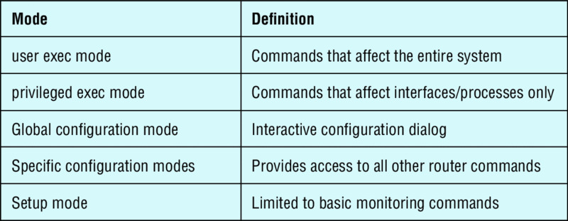
-
Using the given output, what type of interface is shown?
[output cut] Hardware is MV96340 Ethernet, address is 001a.2f55.c9e8 (bia 001a.2f55.c9e8) Internet address is 192.168.1.33/27 MTU 1500 bytes, BW 100000 Kbit, DLY 100 usec, reliability 255/255, txload 1/255, rxload 1/255- 10 Mb
- 100 Mb
- 1000 Mb
- 1000 MB
-
Which of the following commands will configure all the default VTY ports on a switch?
Switch#line vty 0 4Switch(config)#line vty 0 4Switch(config-if)#line console 0Switch(config)#line vty all
-
Which of the following commands sets the privileged mode password to Cisco and encrypts the password?
enable secret password Ciscoenable secret ciscoenable secret Ciscoenable password Cisco
-
If you wanted administrators to see a message when logging into the switch, which command would you use?
message banner motdbanner message motdbanner motdmessage motd
-
Which of the following prompts indicates that the switch is currently in privileged mode?
Switch(config)#Switch>Switch#Switch(config-if)
-
What command do you type to save the configuration stored in RAM to NVRAM?
Switch(config)#copy current to startingSwitch#copy starting to runningSwitch(config)#copy running-config startup-configSwitch#copy run start
-
You try to telnet into SF from router Corp and receive this message:
Corp#telnet SF
Trying SF (10.0.0.1)...Open

Password required, but none set
[Connection to SF closed by foreign host]
Corp#
Which of the following sequences will address this problem correctly?
-
Corp(config)#line console 0Corp(config-line)#password passwordCorp(config-line)#login -
SF config)#line console 0SF(config-line)#enable secret passwordSF(config-line)#login -
Corp(config)#line vty 0 4Corp(config-line)#password passwordCorp(config-line)#login -
SF(config)#line vty 0 4SF(config-line)#password passwordSF(config-line)#login
-
-
Which command will delete the contents of NVRAM on a switch?
delete NVRAMdelete startup-configerase flasherase startup-configerase start
-
What is the problem with an interface if you type
show interface g0/1and receive the following message?Gigabit 0/1 is administratively down, line protocol is down- The keepalives are different times.
- The administrator has the interface shut down.
- The administrator is pinging from the interface.
- No cable is attached.
-
Which of the following commands displays the configurable parameters and statistics of all interfaces on a switch?
show running-configshow startup-configshow interfacesshow versions
-
If you delete the contents of NVRAM and reboot the switch, what mode will you be in?
- Privileged mode
- Global mode
- Setup mode
- NVRAM loaded mode
-
You type the following command into the switch and receive the following output:
Switch#show fastethernet 0/1
            ^
% Invalid input detected at '^' marker.
Why was this error message displayed?
- You need to be in privileged mode.
- You cannot have a space between
fastethernetand0/1. - The switch does not have a FastEthernet 0/1 interface.
- Part of the command is missing.
-
You type
Switch#sh rand receive a% ambiguous commanderror. Why did you receive this message?- The command requires additional options or parameters.
- There is more than one
showcommand that starts with the letter r. - There is no
showcommand that starts with r. - The command is being executed from the wrong mode.
-
Which of the following commands will display the current IP addressing and the layer 1 and 2 status of an interface? (Choose two.)
show versionshow interfacesshow controllersshow ip interfaceshow running-config
-
At which layer of the OSI model would you assume the problem is if you type
show interface serial 1and receive the following message?Serial1 is down, line protocol is down- Physical layer
- Data Link layer
- Network layer
- None; it is a router problem.