Chapter 8
MPLS and L3VPNs
Lab 1: Configuring Label Distribution Protocol

This lab should be conducted on the Enterprise POD.
Lab Setup:
If you are using EVE-NG, and you have imported the EVE-NG topology from the EVE-NG-Topology folder, ignore the following tasks and use Lab-1- Configuring Label Distribution Protocol in the MPLS folder in EVE-NG.
To copy and paste the initial configurations, go to the Initial-config folder → MPLS folder → Lab-1.
Task 1
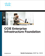
Configure OSPF Area 0 on all links in the previous topology except the Loopback1 interfaces. Configure the OSPF router IDs of these routers to be 0.0.0.x, where x is the router number.
Task 2
Configure Label Distribution Protocol on the links interconnecting the routers in this topology. Ensure that the LDP ID is based on the IP address assigned to the Loopback0 interfaces of these routers. You may override a command from the previous task to accomplish this task.
Task 3
Configure the interval for LDP neighbor discovery to be 15 seconds, with a hold timer of 45 seconds on all LSRs.
Task 4
Configure the session keepalives and hold timers of all routers to 30 and 90 seconds, respectively.
Task 5
Configure the LDP router ID of R1 to be its Loopback1 interface. You should not reload the router to accomplish this task.
Task 6
The MPLS label space on a router is platform dependent. By default, the routers begin numbering the labels from 16 up to 100,000. Change the MPLS label space such that the routers use the following label ranges:
Router | Label Range |
|---|---|
R1 | 100–199 |
R2 | 200–299 |
R3 | 300–399 |
R4 | 400–499 |
R5 | 500–599 |
R6 | 600–699 |
R7 | 700–799 |
Task 7
Examine and describe the control plane for the 7.7.7.7/32 prefix.
Task 8
Examine and describe the data plane for the 7.7.7.7/32 prefix, starting from R1.
Task 9
Configure LDP conditional label advertising to exclude the links that interconnect the routers in this topology.
Task 10
To test the effects of TTL propagation, remove the mpls ip command from the G0/6 interface of R7, the G0/7 interface of R6, the G0/2 interface of R1, and the G0/1 interface of R2. R1 and R7 will pose as customer routers that do not have MPLS enabled. From R7, you will test the connection to 1.1.1.1 by using a traceroute.
Task 11
Reconfigure the appropriate router/s such that a traceroute from R7 to 1.1.1.1 or from R1 to 7.7.7.7 will not display the links from the provider’s network.
Task 12
Remove the mpls ip command from all interfaces of the routers within the cloud—that is, R2, R3, R4, R5, and R6. Verify the configuration.
Task 13
Enable LDP on all the links connecting the routers to each other. Do not use the mpls ip interface configuration command or a global configuration command to accomplish this task.
Task 14
Configure a GigabitEthernet connection between R3 and R5, using the following parameters and policy:
R3: G0/5, 35.1.1.3 /24
R5: G0/3, 35.1.1.5 /24
These links should be included in OSPF Area 0.
Task 15
Configure the appropriate router/s such that a failure in one of the links between R3 and R5 does not tear down the LDP session between the two LSRs. Do not configure a GRE or an IPnIP tunnel to accomplish this task.
Task 16
Erase the startup configuration of the routers and reload the devices before proceeding to the next lab.
Lab 2: Static and RIPv2 Routing in a VPN
Lab Setup:
If you are using EVE-NG, and you have imported the EVE-NG topology from the EVE-NG-Topology folder, ignore the following tasks and use Lab-2- Static and RIPv2 Routing in a VPN in the MPLS folder in EVE-NG.
To copy and paste the initial configurations, go to the Initial-config folder → MPLS folder → Lab-2.
Task 1
Configure OSPF on the core MPLS routers, R2 through R6. Run OSPF Area 0 on the Lo0 interfaces and the links that connect these routers to each other. Configure the OSPF router IDs of R2, R3, R4, R5, and R6 as 0.0.0.2, 0.0.0.3, 0.0.0.4, 0.0.0.5, and 0.0.0.6, respectively.
Task 2
Configure LDP between the core routers (R2 through R6). Ensure that each of these routers uses its Loopback0 interface as its LDP router ID. The core MPLS routers (R2 through R6) should use the following label ranges:
R2: 200–299
R3: 300–399
R4: 400–499
R5: 500–599
R6: 600–699
Task 3
Configure MP-iBGP between R2 and R6 as they represent the provider edge routers in this topology in AS 100. Do not allow the BGP peers to share IPv4 routing information by default. The only BGP peering relationship should be VPNv4.
Task 4
Configure virtual routing and forwarding (VRF) instances on R2 and R6 with the following RD and RT values:
On R2, a VRF instance named CA for Customer A (R1)
Route distinguisher (RD): 1:10
Route target (RT): 1:100
On R6, a VRF instance named CB for Customer A (R2)
Route distinguisher (RD): 1:20
Route target (RT): 1:100
Task 5
Configure a static default route on each customer router located in VRF instances CA and CB. Configure these static routes to point to their respective PE router (R2 for R1 and R6 for R7). The PE routers (R2 and R6) should each be configured with a static route that reaches the loopback and the GigabitEthernet interface of the customer router. R2 and R6 should be able to see both static routes in their BGP tables.
Task 6
Remove the static routes and replace the current method of routing between the PEs and customers with the RIPv2 routing protocol.
Task 7
Erase the startup configuration of these routers and reload the devices before proceeding to the next lab.
Lab 3: EIGRP Routing in a VPN

Lab Setup:
If you are using EVE-NG, and you have imported the EVE-NG topology from the EVE-NG-Topology folder, ignore the following tasks and use Lab-3- EIGRP Routing in a VPN in the MPLS folder in EVE-NG.
To copy and paste the initial configurations, go to the Initial-config folder → MPLS folder → Lab-3.
Task 1
Configure OSPF on the core MPLS routers R2(PE-2), R3(P-3), and R4(PE-4). Run OSPF Area 0 on the:
G0/3 interface of R2
G0/3 interface of R4
G0/2 and G0/4 interfaces of R3
Loopback interfaces of these three routers
The OSPF router IDs of these routers should be set to 0.0.0.x, where x is the router number.
Task 2
Configure LDP between the core routers. These routers should use their Loopback0 interfaces as their LDP router IDs. The core MPLS routers (R2, R3, and R4) should use the following label ranges:
R2: 200–299
R3: 300–399
R4: 400–499
Task 3
Configure an MP-BGP peer session for AS 100 between R2 and R4 as they represent the provider edge routers in this topology. Do not allow the BGP peers to share IPv4 routing information by default. The only BGP peering relationship should be VPNv4.
Task 4
Configure VRF instances on R2 and R4 and enable VRF forwarding on the interfaces of these two routers based on the following chart:
PE | VRF | RD | RT | Interface |
|---|---|---|---|---|
R2 | 11 | 1:10 | 1:156 | G0/1 |
R4 | 55 66 | 1:50 1:60 | 1:156 1:156 | G0/5 G0/6 |
You should configure an address family when configuring VRF 66.
Task 5
Configure the following:
EIGRP AS 100 between R1 and R2 (PE-2)
EIGRP AS 100 between R4 (PE-4) and R5
EIGRP 600 between R4 (PE-4) and R6
Task 6
Configure the PE routers (R2 and R4) so the CE routers (R1, R5, and R6) can see EIGRP routes advertised from the other CE routers and have reachability to them.
Task 7
Erase the startup configuration of these routers and reload the devices before proceeding to the next lab.
Lab 4: EIGRP Site-of-Origin

Lab Setup:
If you are using EVE-NG, and you have imported the EVE-NG topology from the EVE-NG-Topology folder, ignore the following tasks and use Lab-4- EIGRP Site-of-Origin in the MPLS folder in EVE-NG.
To copy and paste the initial configurations, go to the Initial-config folder → MPLS folder → Lab-4.
Task 1
Configure OSPF Area 0 on the following interfaces:
R1: Lo0 and G0/2
R2: Lo0 and G0/1
Configure the OSPF router IDs of these two routers as 0.0.0.x, where x is the router number.
Configure EIGRP AS 100 in named mode on the following interfaces:
R3: Lo0 and G0/4
R4: Lo0 and G0/3
Task 2
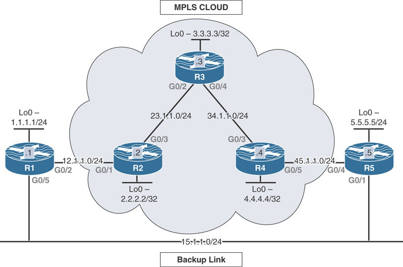
Configure the PE routers (R1 and R2) to support MPLS VPN using AS 65001 and using their Loopback0 interfaces. Use the following parameters for VRF configuration:
VRF name | TST |
RD on R1 | 1:10 |
RD on R2 | 1:20 |
Route target on both | 34:34 |
PE-CE routing protocol | EIGRP 100 |
Ensure full connectivity between the customer’s (R3 and R4) routes. You should configure named mode where possible.
Task 3
Configure the appropriate routers to prevent the local routes from being learned from the backbone. Do not configure R3 or R4, access lists, or prefix lists to accomplish this task.
Task 4
After configuring the previous task, it is obvious that there is no redundancy. If the CE routers (R3 and R4) lose their directly connected link, they will have no reachability to each other’s routes. Configure the appropriate router/s based on the following policy:
If the link between R3 and R4 is up, they should use each other as the next hop to reach the routes they are advertising.
If the link between R3 and R4 is down, they should go through the MPLS cloud to reach each other’s routes.
You should configure and test two different solutions to accomplish this task.
Task 5
Erase the startup configuration of the routers and reload the devices before proceeding to the next lab.
Lab 5: OSPF Routing in a VPN

Lab Setup:
If you are using EVE-NG, and you have imported the EVE-NG topology from the EVE-NG-Topology folder, ignore the following tasks and use Lab-5- OSPF Routing in a VPN in the MPLS folder in EVE-NG.
To copy and paste the initial configurations, go to the Initial-config folder → MPLS folder → Lab-5.
Task 1
Configure OSPF on the core MPLS routers (R2, R3, R4, R5, and R6). Run OSPF Area 0 on the following:
G0/3 interface of R2
G0/2 and G0/4 interfaces of R3
G0/3 and G0/5 interfaces of R4
G0/4 and G0/6 interfaces of R5
G0/5 interface of R6
Loopback0 interfaces of these routers
Configure the OSPF router IDs of these routers to be 0.0.0.x, where x is the router number.
Task 2
Configure LDP on the core routers. These routers should use their Loopback0 interfaces as their LDP router IDs. The core MPLS routers (R2, R3, R4, R5, and R6) should use the following label ranges:
R2: 200–299
R3: 300–399
R4: 400–499
R5: 500–599
R6: 600–699
Task 3
Configure MP-BGP peer session between R2 and R6 as they represent the provider edge routers in this topology in AS 100. Do not allow the BGP peers to share IPv4 routing information by default. The only BGP peering relationship should be VPNv4.
Task 4
Configure VRF instances on R2 and R6 and enable VRF forwarding on the interfaces of these two routers based on the following chart:
Router | VRF | RD | RT | Interface |
|---|---|---|---|---|
R2 | 99 11 | 1:90 1:10 | 1:100 1:100 | G0/0 G0/1 |
R6 | 88 77 | 1:80 1:70 | 1:100 1:100 | G0/8 G0/7 |
Task 5
Configure customers R1, R9, R7, and R8 with a VRF service that incorporates OSPF as the routing protocol. R2 should use OSPF process IDs 11 and 99 for R1 and R9, respectively. R6 should use process IDs 77 and 88 for R7 and R8, respectively.
All directly connected interfaces of R1 should be configured in Area 1 except R1’s Lo1 interface. R1 should redistribute its Lo1 interface in this routing domain.
All directly connected interfaces of R9 should be configured in Area 0.
All directly connected interfaces of R7 should be configured in Area 7.
All directly connected interfaces of R8 should be configured in Area 8.
Task 6
Erase the startup configuration of the routers and reload the devices before proceeding to the next lab.
Lab 6: Backdoor Links and OSPF
Lab Setup:
If you are using EVE-NG, and you have imported the EVE-NG topology from the EVE-NG-Topology folder, ignore the following tasks and use Lab-6- Backdoor Links and OSPF in the MPLS folder in EVE-NG.
To copy and paste the initial configurations, go to the Initial-config folder → MPLS folder → Lab-6.
Task 1
Configure OSPF on the core MPLS routers (R2, R3, and R4). Run OSPF Area 0 on the links and Lo0 interfaces interconnecting these routers. Configure the OSPF router IDs of these routers to be 0.0.0.x, where x is the router number.
Task 2
Configure LDP between the core routers. These routers should use their Loopback0 interfaces as their LDP router IDs. The core MPLS routers (R2, R3, and R4) should use the following label ranges:
R2: 200–299
R3: 300–399
R4: 400–499
Task 3
Configure MP-BGP peer session between R2 and R4 as they represent the provider edge routers in this topology in AS 100. Do not allow the BGP peers to share IPv4 routing information by default. The only BGP peering relationship should be VPNv4.
Task 4
Configure a virtual routing and forwarding (VRF) instance with the name aa, the route distinguisher (RD) 1:10, and the route target (RT) 1:100 for R1 (the customer) on R2 (the PE router). On R4, use the same route targets for the VRF instance but configure the RD to be 1:50 and the name of the VRF to be aa.
Task 5
Configure OSPF using the same process ID on the customer routers (R1 and R5). Configure MP-BGP such that the customer routers can see each other’s routes. Customer routers should advertise their Lo0 interfaces with the correct mask.
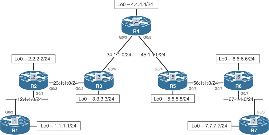
Task 6
Configure the G0/5 interface of the customer router R1 and the G0/1 interface of the customer router R5 as a backup link. Ensure that the MPLS service is preferred over the backup link.
Task 7
Provide another solution to the problem that is different from the one in the previous task.
Task 8
To satisfy the customer, who is complaining about two additional routes in their routing table, remove them. These are the IP addresses assigned to the Lo24 interface of R2 and Lo42 interface of R4.
Task 9
Erase the startup configuration of the routers and reload the devices before proceeding to the next lab.
Lab 7: BGP Routing in a VPN
Lab Setup:
If you are using EVE-NG, and you have imported the EVE-NG topology from the EVE-NG-Topology folder, ignore the following tasks and use Lab-7- BGP Routing in a VPN in the MPLS folder in EVE-NG.
To copy and paste the initial configurations, go to the Initial-config folder → MPLS folder → Lab-7.
Task 1
Configure OSPF on the core MPLS routers (R2, R3, and R4). Run OSPF Area 0 on the links and Lo0 interfaces interconnecting these routers. Configure the OSPF router IDs of these routers to be 0.0.0.x, where x is the router number.
Task 2
Configure LDP between the core routers. These routers should use their Loopback0 interfaces as their LDP router IDs. The core MPLS routers (R2, R3, and R4) should use the following label ranges:
R2: 200–299
R3: 300–399
R4: 400–499
Task 3
Configure MP-BGP peer session between R2 and R4 as they represent the provider edge routers in this topology in AS 100. Do not allow the BGP peers to share IPv4 routing information by default. The only BGP peering relationship should be VPNv4.
Task 4
Configure a virtual routing and forwarding (VRF) instance with the name aa, the route distinguisher (RD) 1:10, and the route target (RT) 1:100 for R1 (the customer) on R2 (the PE router). On R4, use the same route targets for the VRF instance but configure the RD to be 1:50 and the name of the VRF to be aa.
Task 5
Configure BGP as the MPLS routing protocol between the CEs (R1 and R5) and their respective PEs (R2 and R4). The customer AS of 65015 should be assigned to both customer sites.
Task 6
Erase the startup configuration of the routers and reload the devices before proceeding to the next lab.
Lab 8: MPLS and NAT

Lab Setup:
If you are using EVE-NG, and you have imported the EVE-NG topology from the EVE-NG-Topology folder, ignore the following tasks and use Lab-8- MPLS and NAT in the MPLS folder in EVE-NG.
To copy and paste the initial configurations, go to the Initial-config folder → MPLS folder → Lab-8.
Task 1
Configure OSPF on the core MPLS routers (R2, R3, and R4). Run OSPF Area 0 on the links and Lo0 interfaces interconnecting these routers. Configure the OSPF router IDs of these routers to be 0.0.0.x, where x is the router number. Configure the CE routers, R1 and R5, with a static default route pointing to their next hop router.
Task 2
Configure LDP between the core routers. These routers should use their Loopback0 interfaces as their LDP router IDs.
Task 3
Configure MP-BGP between R2 and R4 as they represent the provider edge routers in this topology in AS 100. The only BGP peering relationship should be VPNv4. These two neighbors should use their Lo0 interfaces for their peering.
Task 4
Configure the following VRF instances, RDs, and route targets on the PE routers, based on the following chart:
Router | VRF Name | RD | Route Target | Interface |
|---|---|---|---|---|
R2 | 111 | 1:10 | route-target both 1:100 | G0/1 |
R4 | 555 | 1:50 | route-target both 1:100 | G0/5 |
Task 5
Ensure that the hosts in Site-1 can access the server in Site-2 and vice versa. Configure NAT on the CE routers (R1 and R5). Use the following translation chart:
Router | Inside Local | Inside Global |
|---|---|---|
R1 | 10.1.1.1 10.1.1.2–10.1.1.5 | 100.1.1.1 100.1.1.2–100.1.1.5 |
R5 | 10.1.1.1 10.1.1.2–10.1.1.5 | 200.1.1.1 200.1.1.2–200.1.1.5 |
Task 6
Erase the startup configuration of the routers and reload the devices before proceeding to the next lab.
Lab 9: Route Targets, Import Maps, and Export Maps

Lab Setup:
If you are using EVE-NG, and you have imported the EVE-NG topology from the EVE-NG-Topology folder, ignore the following tasks and use Lab-9-Route-Targets-Import maps and Export maps in the MPLS folder in EVE-NG.
To copy and paste the initial configurations, go to the Initial-config folder → MPLS folder → Lab-9.
Task 1
Configure OSPF on the core MPLS routers (PE-1, PE-2, PE-3, PE-4, and P-5). Run OSPF Area 0 on the G0/5 interfaces of PE-1(R1), PE-2(R2), PE-3 (R3), and PE-4(R4), the G0/1, G0/2, G0/3, and G0/4 interfaces of P-5(R5), and the loopback interfaces of these routers. Configure the OSPF router IDs of these routers to be 0.0.0.x, where x is the router number.
Task 2
Configure LDP between the core routers. These routers should use their Loopback0 interfaces as their LDP router IDs. The core MPLS routers (PE-1, PE-2, PE-3, PE-4, and P-5) should use the following label ranges:
PE-1: 100–199
PE-2: 200–299
PE-3: 300–399
PE-4: 400–499
P-5: 500–599
Task 3
Configure MP-BGP peer session between all PE routers using AS 100. Do not allow the BGP peers to share IPv4 routing information by default. The only BGP peering relationship should be VPNv4.
Task 4
Configure VRF instances and RDs on the PE routers and enable VRF forwarding on the interfaces of these routers based on the following chart:
Router | VRF | RD | Interface |
|---|---|---|---|
PE-1 | 66 | 1:60 | G0/6 |
PE-2 | 77 | 1:70 | G0/7 |
PE-3 | 88 | 1:80 | G0/8 |
PE-4 | 99 | 1:90 | G0/0 |
Do not configure route targets.
Task 5
Configure routing between the CE and the PE routers, based on the following chart:
CE Router | PE Router | Routing Protocol |
|---|---|---|
R6 | PE-1 | EIGRP 100 |
R7 | PE-2 | OSPF area 0 |
R8 | PE-3 | RIPv2 |
R9 | PE-4 | BGP AS 200 |
Task 6
Configure the appropriate PE/s such that routers R6 and R7 can exchange routes and be in the same VPN.
Task 7
Configure the appropriate PE/s such that routers R7 and R9 can exchange routes and be in the same VPN.
Task 8
Configure the appropriate PE/s such that routers R8 and R9 can exchange routes and be in the same VPN.
Task 9
Configure the appropriate PE/s such that routers R6 and R8 can exchange routes and be in the same VPN.
Task 10
Configure PE-1 such that R6 only receives networks 7.7.7.7/32 and 8.8.8.0/24. This may affect the reachability achieved in some of the previous tasks.
Task 11
Configure the following loopback interfaces on R6, R7, and R8:
R6: Loopback200, 200.1.1.6/32
R7: Loopback200, 200.1.1.7/32
R8: Loopback200, 200.1.1.8/32
Task 12
Erase the startup configuration of the routers and reload the devices before proceeding to the next lab.
Lab 10: Internet Access Methods: Partial Internet Routes

Lab Setup:
If you are using EVE-NG, and you have imported the EVE-NG topology from the EVE-NG-Topology folder, ignore the following tasks and use Lab-10- Internet Access Methods Partial Internet Routes in the MPLS folder in EVE-NG.
To copy and paste the initial configurations, go to the Initial-config folder → MPLS folder → Lab-10.
Task 1
Configure the core routers (R3, R4, R5, and R6) to support MPLS VPN using AS 200.
R5 in AS 200 should be configured with an IPv4 peering to the physical interface of R7 in AS 300. R7 should advertise its Lo100 and Lo200 interfaces in this AS.
R3 in AS 200 should be configured with an IPv4 peering to the G0/0 interface of R1 in AS 100.
Task 2
Configure a VRF instance called aaa on R3 and R6 (the PE routers).
Apply this VRF instance to the G0/1 interface of R3 facing R1 and the G0/2 interface of R6 facing R2 (the CE routers).
Use the RD 1:10 and the route target 1:100 on R3 and the RD 1:20 with the same RT configured on R3.
Task 3
Ensure the customers R1 and R2 only receive partial Internet routes using the following policies:
Only R1 should receive the partial Internet routes.
R2 should go through R1 to reach the partial routes.
Task 4
Erase the startup configuration on all routers and reload the devices before proceeding to the next lab.