
Practice Lab 2 Solutions
Section 1: Perimeter Security
In Lab 1, you initialized perimeter security services and configured some fundamental features. This section adds more advanced features on the Cisco ASAs, including configuring IPv6, botnet traffic filtering and redundancy and management services. There is also an exercise using the Cisco IOS zone-based firewall (ZFW), which has replaced CBAC as the firewall solution on Cisco IOS routers. ZFW has been updated to allow support for Cisco TrustSec and security group tagging, and this will be incorporated into the exercise in this lab.
Solution and Verification for Exercise 1.1: Configure a Redundant Interface on ASA2
Skills Tested:
![]() Configuring high availability on the Cisco ASA using a redundant interface
Configuring high availability on the Cisco ASA using a redundant interface
Solution and Verification
There are several ways to implement high availability (HA) on the Cisco ASA. Redundant interface failover is one form of HA that provides link redundancy in a single device. The down side of this form of HA is that if there is a problem other than an interface issue on the ASA itself, or on any connected device (on the tracked interface), there will still be service disruption issues. The benefits of a redundant interface are that configuration is fairly simple, there is no need to provision a separate link to transfer state information between devices, and one MAC address is used on the redundant interface (taken from the first physical interface [the primary] added to the bundle, or user defined) that does not change as the interfaces change state. The use of one MAC address perpetually means upstream devices will not have to relearn IP-to-MAC address bindings, minimizing disruption to applications. This is also useful if, for example, a security technique such as IP source guard is configured on a switchport connecting the ASA.
The key change to the configuration of ASA2 when moving from physical interfaces to a logical interface is that the parameters associated with the physical interface in a non-HA deployment, such as nameif, IP addresses, and security level, are now configured on the redundant interface. Physical interfaces need to be defined only as member interfaces. Multiple member interfaces are associated with one redundant interface.
You must be sure to reapply all access lists, service policies, and anything else that had previously been applied to the outside interface. These policies are automatically removed when an interface nameif is deleted.
For all verification syntax that follows:
![]() Required output appears in red
Required output appears in red
![]() Variable syntax appears in green
Variable syntax appears in green
Verify whether the physical interfaces Gig0/0 and Gig0/1 are up and are members of the logical interface Redundant1. No interface parameters, such as an IP address, will be displayed because they are now defined on the redundant interface.
ASA2# show interface gig0/0
Interface GigabitEthernet0/0 "", is up, line protocol is up
Hardware is i82546GB rev03, BW 1000 Mbps, DLY 10 usec
Auto-Duplex(Full-duplex), Auto-Speed(1000 Mbps)
Input flow control is unsupported, output flow control is off
Active member of Redundant1
MAC address 0015.c695.c646, MTU not set
IP address unassigned
ASA2# show interface gig0/1
Interface GigabitEthernet0/1 "", is up, line protocol is up
Hardware is i82546GB rev03, BW 1000 Mbps, DLY 10 usec
Auto-Duplex(Full-duplex), Auto-Speed(1000 Mbps)
Input flow control is unsupported, output flow control is off
Standby member of Redundant1
MAC address 0015.c695.c647, MTU not set
IP address unassigned
Verify whether the redundant interface is up and has an IP address assigned. Note the MAC address used by the redundant interface. It is taken from the first physical interface member added to the grouping. This can be overridden by a user-defined MAC address via the mac-address mac_address command.
ASA2# show interface redundant 1
Interface Redundant1 "outside", is up, line protocol is up
Hardware is i82546GB rev03, BW 1000 Mbps, DLY 10 usec
Auto-Duplex(Full-duplex), Auto-Speed(1000 Mbps)
Input flow control is unsupported, output flow control is off
MAC address 0015.c695.c646, MTU 1500
IP address 10.50.50.20, subnet mask 255.255.255.0
Verify whether all interface parameters have now been correctly applied to the redundant interface:
ASA2# show nameif
Interface Name Security
GigabitEthernet0/2 inside 100
GigabitEthernet0/3 dmz 50
Redundant1 outside 0
Checking the routing table for completeness and being able to successfully ping the next hop router will verify protocol connectivity.
ASA2# show route
Codes: C - connected, S - static, I - IGRP, R - RIP, M - mobile, B - BGP
D - EIGRP, EX - EIGRP external, O - OSPF, IA - OSPF inter area
N1 - OSPF NSSA external type 1, N2 - OSPF NSSA external type 2
E1 - OSPF external type 1, E2 - OSPF external type 2, E - EGP
i - IS-IS, L1 - IS-IS level-1, L2 - IS-IS level-2, ia - IS-IS inter area
* - candidate default, U - per-user static route, o - ODR
P - periodic downloaded static route
Gateway of last resort is 10.50.50.5 to network 0.0.0.0
C 10.50.50.0 255.255.255.0 is directly connected, outside
S 10.3.3.0 255.255.255.0 [1/0] via 10.50.30.3, dmz
S 10.4.4.0 255.255.255.0 [1/0] via 10.50.30.4, dmz
O 10.7.7.7 255.255.255.255 [110/11] via 10.50.40.7, 0:00:18, inside
C 10.50.40.0 255.255.255.0 is directly connected, inside
C 10.50.30.0 255.255.255.0 is directly connected, dmz
O 10.50.9.0 255.255.255.0 [110/11] via 10.50.50.5, 0:00:18, outside
O E2 10.50.100.0 255.255.255.0 [110/20] via 10.50.50.5, 0:00:18, outside
O E2 10.50.90.0 255.255.255.0 [110/20] via 10.50.50.5, 0:00:18, outside
O 10.50.77.0 255.255.255.0 [110/11] via 10.50.50.5, 0:00:18, outside
O 10.50.70.0 255.255.255.0 [110/11] via 10.50.50.5, 0:00:18, outside
O E2 192.168.2.0 255.255.255.0 [110/20] via 10.50.50.5, 0:00:18, outside
O*E2 0.0.0.0 0.0.0.0 [110/1] via 10.50.50.5, 0:00:18, outside
ASA2# ping outside 10.50.50.5
Type escape sequence to abort.
Sending 5, 100-byte ICMP Echos to 10.50.50.5, timeout is 2 seconds:
!!!!!
Success rate is 100 percent (5/5), round-trip min/avg/max = 1/2/10 ms
Configuration
ASA2
hostname ASA2
interface Redundant1
member-interface GigabitEthernet0/0
member-interface GigabitEthernet0/1
nameif outside
security-level 0
ip address 10.50.50.20 255.255.255.0
ospf priority 0
Solution and Verification for Exercise 1.2: SSH Management Authentication and Local Command Authorization on ASA1
Skills Tested
![]() Configuring SSH server functionality on the Cisco ASA for management purposes
Configuring SSH server functionality on the Cisco ASA for management purposes
![]() Defining local command authorization policies per privilege level
Defining local command authorization policies per privilege level
![]() Manipulating session parameters for SSH
Manipulating session parameters for SSH
Solution and Verification
The Cisco ASA can be managed using several applications: Telnet, HTTPS, and SSH. In this exercise, SSH server functionality is required on ASA1. When the ASA is configured in multi-context mode, management services and functions are enabled in the admin context. When you enable SSH and define users for access, you can configure per-user command authorization. In this exercise, the command authorization is done via the local database, but it can also be done using TACACS+ to an external authentication server. Command authorization defines an explicit set of ASA commands that is mapped to a privilege level to limit access for users granted that same privilege level upon login to the ASA.
You also can tune SSH access and session parameters. You can change parameters, such as session idle timeouts, globally or set them explicitly for certain groups of users using the Modular Policy Frameword (MPF). The default idle timeout is 5 minutes, and it can be used for sessions sourced from IP addresses 192.168.1.0/24. You should use the ASA MPF configuration syntax to change the idle timeout for sessions sourced from 192.168.2.0/24.
For all verification syntax that follows:
![]() Required output appears in red
Required output appears in red
![]() Required tasks appear in indigo
Required tasks appear in indigo
![]() Variable syntax appears in green
Variable syntax appears in green
The first step to configuring SSH server is to define an RSA key pair for ASA1. The modulus to use is 768 bits. SSH clients will be prompted to accept this key the first time they connect to ASA1. Verify whether the SSH server key has been generated:
ASA1/admin# show crypto key mypubkey rsa
Key pair was generated at: 03:37:36 UTC Aug 21 2013
Key name: <Default-RSA-Key>
Usage: General Purpose Key
Modulus Size (bits): 768
Key Data:
307c300d 06092a86 4886f70d 01010105 00036b00 30680261 00bb8204 bdf8500e
7abf837d d9b2e0c9 a7e558c3 57e559b7 ea514afb ea1913f9 2cfdd0db fb944a53
23fd196f 38428fc2 26d2aeb9 e8060139 e0cb5f58 f089052a 8bdca9be a9357b46
a74067ee 164efd6f 898b504c f0da88af 695af6b1 7fd34458 0b020301 0001
Verify the global SSH server settings. The session idle timeout is 5 minutes by default. More granular control can be applied using the MPF:
ASA1/admin# show ssh
Timeout: 5 minutes
Versions allowed: 1 and 2
192.168.1.0 255.255.255.0 mgmt
192.168.2.0 255.255.255.0 mgmt
To verify the MPF policy created to apply the 1 minute idle timeout to SSH sessions sourced from 192.168.2.0/24, show the service policy applied to the management interface. The class map will identify the traffic of interest; namely, SSH sourced from 192.168.2.0/24. The policy map enforces actions on that traffic; in this case, the 1 minute idle timeout.
access-list ssh-acl extended permit tcp 192.168.2.0 255.255.255.0 any eq 22
class-map mgmt-class
match access-list ssh-acl
ASA1/admin# show service-policy int mgmt
Interface mgmt:
Service-policy: mgmt-policy
Class-map: mgmt-class
Set connection policy: drop 0
Set connection timeout policy:
idle 0:01:00
DCD: disabled, retry-interval 0:00:15, max-retries 5
DCD: client-probe 0, server-probe 0, conn-expiration 0
To verify the SSH configuration and command authorization policy, connect from SW1:
Step 1. Log in with the privilege level 15 account:
SW1# ssh -l cisco 192.168.1.20
Password: cisco
Type help or '?' for a list of available commands.
ASA1/admin>en
Password: *****
ASA1/admin# show running-config
: Saved
:
ASA Version 8.4(5) <context>
!
hostname ciscoasa
ASA1/admin# show ssh session
SID Client IP Version Mode Encryption Hmac State Username
0 192.168.1.5 2.0 IN aes128-cbc sha1 SessionStarted cisco
OUT aes128-cbc sha1 SessionStarted cisco
Step 2. Log in with the privilege level 5 account:
SW1# ssh -l support 192.168.1.20
Password: cisco
Type help or '?' for a list of available commands.
ASA1/admin>
ASA1/admin> en 5
Password: *****
ASA1/admin# show running-config
^
ERROR: % Invalid input detected at '^' marker.
ERROR: Command authorization failed
Verify whether the authorized commands succeed:
ASA1/admin# show xlate
0 in use, 0 most used
ASA1/admin# show route
Codes: C - connected, S - static, I - IGRP, R - RIP, M - mobile,
B - BGP
D - EIGRP, EX - EIGRP external, O - OSPF, IA - OSPF inter area
N1 - OSPF NSSA external type 1, N2 - OSPF NSSA external type 2
E1 - OSPF external type 1, E2 - OSPF external type 2, E - EGP
i - IS-IS, L1 - IS-IS level-1, L2 - IS-IS level-2, ia - IS-IS
inter area
* - candidate default, U - per-user static route, o - ODR
P - periodic downloaded static route
Gateway of last resort is 192.168.1.5 to network 0.0.0.0
C 192.168.1.0 255.255.255.0 is directly connected, mgmt
S* 0.0.0.0 0.0.0.0 [1/0] via 192.168.1.5, mgmt
ASA1/admin#
ASA1/admin# show ssh session
SID Client IP Version Mode Encryption Hma State Username
0 192.168.1.5 2.0 IN aes128-cbc sha1 SessionStarted support
OUT aes128-cbc sha1 SessionStarted support
Configuration
username support password cisco privilege 5
username cisco password cisco
aaa authentication ssh console LOCAL
ssh 192.168.1.0 255.255.255.0 mgmt
ssh 192.168.2.0 255.255.255.0 mgmt
object-group service ssh tcp
port-object eq ssh
access-list ssh-acl extended permit tcp 192.168.2.0 255.255.255.0 any object-group
ssh
class-map mgmt-class
match access-list ssh-acl
policy-map mgmt-policy
class mgmt-class
set connection timeout idle 0:01:00
!
service-policy mgmt-policy interface mgmt
enable password cisco level 5
enable password cisco
privilege show level 5 mode exec command xlate
privilege show level 5 mode exec command route
Tech Notes
The following are some tips regarding security contexts and command authorization:
![]() AAA settings are discrete per context, not shared among contexts. Make sure you verify the capabilities associated with specific versions of Cisco ASA software.
AAA settings are discrete per context, not shared among contexts. Make sure you verify the capabilities associated with specific versions of Cisco ASA software.
![]() When configuring command authorization, you must configure each security context separately, allowing the enforcement of different command authorizations per security context.
When configuring command authorization, you must configure each security context separately, allowing the enforcement of different command authorizations per security context.
![]() When switching between security contexts, administrators should be aware that the commands permitted for the username specified when they log in might be different in the new context session or that command authorization might not be configured at all in the new context.
When switching between security contexts, administrators should be aware that the commands permitted for the username specified when they log in might be different in the new context session or that command authorization might not be configured at all in the new context.
![]() New context sessions started with the changeto command always use the default enable_15 username as the administrator identity, regardless of which username was used in the previous context session. This behavior can lead to unexpected results if command authorization is not configured for the enable_15 user or if authorizations are different for the enable_15 user than for the user in the previous context session.
New context sessions started with the changeto command always use the default enable_15 username as the administrator identity, regardless of which username was used in the previous context session. This behavior can lead to unexpected results if command authorization is not configured for the enable_15 user or if authorizations are different for the enable_15 user than for the user in the previous context session.
Solution and Verification for Exercise 1.3: Configuring Advanced Network Protection on the ASA
Skills Tested
![]() Configuring botnet traffic filtering using blacklists, whitelists, and DNS snooping on the ASA
Configuring botnet traffic filtering using blacklists, whitelists, and DNS snooping on the ASA
![]() Using syslog to verify botnet traffic filtering
Using syslog to verify botnet traffic filtering
![]() Applying advanced features to the Cisco ASA’s threat detection feature
Applying advanced features to the Cisco ASA’s threat detection feature
![]() Implementing IP audit to provide basic IPS support on the Cisco ASA
Implementing IP audit to provide basic IPS support on the Cisco ASA
Solution and Verification
All the features covered in this exercise are less traditional firewall features available on the ASA. In general, the protection and monitoring provided by threat detection and IP audit would be implemented on an IPS platform. However, in certain scenarios, these features can be useful if they are run periodically to profile the traffic seen on the ASA and devise a deployment plan for an IPS system.
Botnet traffic filtering is an important feature that can protect the hosts in the network from attaching to known malware sites and in turn infecting other devices in the network. It is most useful when combined with a dynamic database service that contains the names of thousands of questionable Internet sites. This enhanced service is easily integrated with the static blacklist used in this exercise.
For all verification syntax that follows:
![]() Required output appears in red
Required output appears in red
![]() Required tasks appear in indigo
Required tasks appear in indigo
Task 1: Botnet Traffic Filtering on ASA1
R2 has been configured as the authoritative DNS server for the ccie.com domain. R6 is configured with R2 (10.50.100.2) as a name server. Telnet to the blacklisted server should fail, although the name should resolve to ensure the DNS query was snooped. The filters should be applied on the outside interface of ASA1/c2. Syslog output is a good way to verify whether the configuration is producing the expected results.
R6# telnet server.ccie.com
Translating "server.ccie.com"...domain server (10.50.100.2)
Translating "server.ccie.com"...domain server (10.50.100.2) [OK]
Trying server.ccie.com (10.10.130.1)...
% Connection timed out; remote host not responding
Verify whether the DNS request from R6 was snooped by ASA1:
ASA1/c2# show dynamic-filter dns-snoop detail
DNS Reverse Cache Summary Information:
1 addresses, 1 names
Next housekeeping scheduled at 19:23:50 UTC Sep 19 2013,
DNS reverse Cache Information:
[10.10.130.1] flags=0x2, type=2, unit=0 b:u:w=1:0:0, cookie=0x751dae80
[server.ccie.com] type=2, ttl=0
If logging was enabled on ASA1, you should see the following output (note the message levels):
%ASA-6-338301: Intercepted DNS reply for name server.ccie.com from
inside:10.50.100.2/53 to
outside:10.50.80.6/52007, matched blacklist
%ASA-6-302016: Teardown UDP connection 824265 for outside:10.50.80.6/52007 to
inside:10.50.100.2/53 duration 0:00:00 bytes 82
%ASA-4-338002: Dynamic Filter monitored blacklisted TCP traffic from
outside:10.50.80.6/16988
(10.50.80.6/16988) to inside:10.10.130.1/23 (10.10.130.1/23), destination
10.10.130.1 resolved
from local list: server.ccie.com, threat-level: very-high, category: admin-added
%ASA-4-338006: Dynamic Filter dropped blacklisted TCP traffic from
outside:10.50.80.6/16988
(10.50.80.6/16988) to inside:10.10.130.1/23 (10.10.130.1/23), destination
10.10.130.1 resolved
from local list: server.ccie.com, threat-level: very-high, category: admin-added
Access to the site server.ccie.com should be blocked because it has been designated a blacklisted site.
ASA1/c2# show dynamic-filter reports top malware-sites
Malware Sites (since last clear)
Site Connections Logged Dropped Threat-level Category
---------------------------------------------------------------------------------
10.10.130.1 (server.ccie.com) 4 4 very-high admin-added
Last clearing of the top sites report: Never
You can verify the whitelisted addresses as follows:
R6# telnet 10.10.110.1
Trying 10.10.110.1 ... Open
ASA1/c2# show dynamic-filter statistics
Enabled on interface outside
Total conns classified 57, ingress 17, egress 40
Total whitelist classified 1, ingress 1, egress 0
Total greylist classified 0, dropped 0, ingress 0, egress 0
Total blacklist classified 56, dropped 56, ingress 16, egress 40
Whitelisted sites are displayed in syslog outputs. The following log messages can help verify the configuration:
%ASA-6-338104: Dynamic Filter monitored whitelisted TCP traffic from
outside:10.50.80.6/52071
(10.50.80.6/52071) to inside:10.10.110.1/23 (10.10.110.1/23), destination
10.10.110.1 resolved
from local list: 10.10.0.0/255.255.0.0
Task 2: Threat Detection on ASA2
Enabling and verifying additional statistics categories is straightforward. Protocol statistics will display any non-UDP or non-TCP IP protocols:
ASA2# show threat-detection statistics protocol
Average(eps) Current(eps) Trigger Total events
OSPF * 89: tot-ses:0 act-ses:0
1-hour Sent byte: 0 0 0 592
1-hour Sent pkts: 0 0 0 7
Port statistics will display UDP and TCP ports for a more in-depth profile of the traffic seen on ASA2:
ASA2# show threat-detection statistics port
Average(eps) Current(eps) Trigger Total events
Isakmp 500: tot-ses:2070 act-ses:1
1-hour Sent byte: 0 0 0 328
1-hour Sent pkts: 0 0 0 2
1-hour Recv byte: 0 0 0 344
1-hour Recv pkts: 0 0 0 2
Task 3: IP Audit
To verify whether attacks are dropped on the outside interface of ASA1/c1, send a large ping that will trigger the fragmented ICMP signature:
R6# ping 192.168.2.5 size 2000
Type escape sequence to abort.
Sending 5, 2000-byte ICMP Echos to 192.168.2.5, timeout is 2 seconds:
.....
IP AUDIT INTERFACE COUNTERS: outside
2011 I ICMP Address Mask Request 0
2012 I ICMP Address Mask Reply 0
2150 A Fragmented ICMP 10
2151 A Large ICMP 0
2154 A Ping of Death 0
A normal-sized ping should register as an informational event on the inside interface of ASA1/c1. Note that the ECHO reply is matched.
R6# ping 192.168.2.5
Type escape sequence to abort.
Sending 5, 100-byte ICMP Echos to 192.168.2.5, timeout is 2 seconds:
!!!!!
Success rate is 100 percent (5/5), round-trip min/avg/max = 1/2/8 ms
IP AUDIT INTERFACE COUNTERS: inside
1100 A IP Fragment Attack 0
1102 A Impossible IP Packet 0
1103 A IP Teardrop 0
2000 I ICMP Echo Reply 5
2001 I ICMP Unreachable 0
Configuration
ASA2
threat-detection basic-threat
threat-detection statistics port
threat-detection statistics protocol
threat-detection statistics access-list
no threat-detection statistics tcp-intercept
ASA1/c1
ip audit name inside info action alarm
ip audit name outside attack action reset
ip audit interface outside outside
ip audit interface inside inside
ASA1/c2
dynamic-filter enable interface outside
dynamic-filter drop blacklist interface outside
dynamic-filter blacklist
name server.ccie.com
dynamic-filter whitelist
address 10.10.110.0 255.255.255.0
address 10.10.120.0 255.255.255.0
class-map dynamic-filter-dns-snoop
match port udp eq domain
policy-map dynamic-filter-dns-snoop
class dynamic-filter-dns-snoop
inspect dns dynamic-filter-snoop
service-policy dynamic-filter-dns-snoop interface outside
Tech Notes
Threat detection statistics can help analyze and manage threats to the Cisco ASA. This information can be used to help the administrator understand usage patterns and devise and configure an IPS policy on a separate sensor device. The threat defense feature can also be configured for scanning; however, this is a processor-intensive feature and should be used with care.
There are two levels of threat detection statistics:
![]() Basic threat detection statistics: Includes information about attack activity for the system as a whole. Basic threat detection statistics are enabled by default and have no performance impact.
Basic threat detection statistics: Includes information about attack activity for the system as a whole. Basic threat detection statistics are enabled by default and have no performance impact.
![]() Advanced threat detection statistics: Tracks activity at an object level, so the ASA can report activity for individual hosts, ports, protocols, or access lists. Advanced threat detection statistics can have a major performance impact, depending on the statistics gathered; only access list statistics are enabled by default.
Advanced threat detection statistics: Tracks activity at an object level, so the ASA can report activity for individual hosts, ports, protocols, or access lists. Advanced threat detection statistics can have a major performance impact, depending on the statistics gathered; only access list statistics are enabled by default.
A summary of IP audit attacks and informational events follows:
1000 I Bad IP Options List
1001 I Record Packet Route
1002 I Timestamp
1003 I Provide s,c,h,tcc
1004 I Loose Source Route
1005 I SATNET ID
1006 I Strict Source Route
1100 A IP Fragment Attack
1102 A Impossible IP Packet
1103 A IP Teardrop
2000 I ICMP Echo Reply
2001 I ICMP Unreachable
2002 I ICMP Source Quench
2003 I ICMP Redirect
2004 I ICMP Echo Request
2005 I ICMP Time Exceed
2006 I ICMP Parameter Problem
2007 I ICMP Time Request
2008 I ICMP Time Reply
2009 I ICMP Info Request
2010 I ICMP Info Reply
2011 I ICMP Address Mask Request
2012 I ICMP Address Mask Reply
2150 A Fragmented ICMP
2151 A Large ICMP
2154 A Ping of Death
3040 A TCP No Flags
3041 A TCP SYN & FIN Flags Only
3042 A TCP FIN Flag Only
3153 A FTP Improper Address
3154 A FTP Improper Port
4050 A Bomb
4051 A Snork
4052 A Chargen
6050 I DNS Host Info
6051 I DNS Zone Xfer
6052 I DNS Zone Xfer High Port
6053 I DNS All Records
6100 I RPC Port Registration
6101 I RPC Port Unregistration
6102 I RPC Dump
6103 A Proxied RPC
6150 I ypserv Portmap Request
6151 I ypbind Portmap Request
6152 I yppasswdd Portmap Request
6153 I ypupdated Portmap Request
6154 I ypxfrd Portmap Request
6155 I mountd Portmap Request
6175 I rexd Portmap Request
6180 I rexd Attempt
6190 A statd Buffer Overflow
Solution and Verification for Exercise 1.4: Configure IPv6 on ASA2
Skills Tested
![]() Basic IPv6 configuration on the Cisco ASA
Basic IPv6 configuration on the Cisco ASA
![]() Understanding IPv6 Neighbor Discovery Protocol
Understanding IPv6 Neighbor Discovery Protocol
Solution and Verification
This exercise requires a basic IPv6 interface configuration. The process of neighbor discovery begins after an IPv6 address is enabled on an interface. IPv6 hosts use Neighbor Discovery Protocol (NDP) to learn their own addresses (if autoconfiguration is required), as well as the addresses of their neighbors, including any gateways. Neighbors are learned through neighbor solicitation (NS) and neighbor advertisement (NA) ICMPv6 messages. Gateways/routers are learned on a segment by sending router solicitation (RS) ICMPv6 messages to which routers will send router advertisement (RA) messages indicating their link prefixes and hop counts. Attackers can use the information in an RA message to do reconnaissance on the network, so these ICMPv6 messages are often suppressed on interfaces where a specific device should not advertise information about itself—for example, on a public-facing interface. In this question, the routers on the same segments as the ASA IPv6 interfaces will advertise themselves as the IPv6 default gateways and the source of any autoconfiguration parameters. ASA2 does not perform this function and will not send RA messages.
For all verification syntax that follows:
![]() Required output appears in red
Required output appears in red
Verify the IPv6 addresses on the inside and DMZ interfaces:
ASA2# show ipv6 int inside
inside is up, line protocol is up
IPv6 is enabled, link-local address is fe80::215:c6ff:fe95:c648
Global unicast address(es):
2001:db8:40::20, subnet is 2001:db8:40::/64
Joined group address(es):
ff02::1
ff02::2
ff02::1:ff00:20
ff02::1:ff95:c648
ICMP error messages limited to one every 100 milliseconds
ICMP redirects are enabled
ND DAD is enabled, number of DAD attempts: 1
ND reachable time is 30000 milliseconds
Hosts use stateless autoconfig for addresses.
ASA2# show ipv6 int dmz
dmz is up, line protocol is up
IPv6 is enabled, link-local address is fe80::215:c6ff:fe95:c649
Global unicast address(es):
2001:db9:30::20, subnet is 2001:db9:30::/64
Joined group address(es):
ff02::1
ff02::2
ff02::1:ff00:20
ff02::1:ff95:c649
ICMP error messages limited to one every 100 milliseconds
ICMP redirects are enabled
ND DAD is enabled, number of DAD attempts: 1
ND reachable time is 30000 milliseconds
Hosts use stateless autoconfig for addresses.
Verify whether RA messages are being suppressed on the inside and DMZ interfaces:
ASA2# show run | begin interface GigabitEthernet0/2
interface GigabitEthernet0/2
nameif inside
security-level 100
ip address 10.50.40.20 255.255.255.0
ipv6 address 2001:db8:40::20/64
ipv6 enable
ipv6 nd suppress-ra
ospf message-digest-key 1 md5 *****
ospf authentication message-digest
ASA2# show run | begin interface GigabitEthernet0/3
interface GigabitEthernet0/3
nameif dmz
security-level 50
ip address 10.50.30.20 255.255.255.0
ipv6 address 2001:db9:30::20/64
ipv6 enable
ipv6 nd suppress-ra
Configuration
interface GigabitEthernet0/2
ipv6 address 2001:db8:40::20/64
ipv6 enable
ipv6 nd suppress-ra
ASA2# show run | begin interface GigabitEthernet0/3
interface GigabitEthernet0/3
ipv6 address 2001:db9:30::20/64
ipv6 enable
ipv6 nd suppress-ra
Tech Notes
IPv6 Addressing Review
IPv6 was created to meet the demand for more IP addresses than IPv4 could accommodate.
IPv6 provides a way to allocate address ranges in a more optimized way due to the large amount of addresses available.
IPv6 Addressing Notation
IPv6 addresses are 128 bits long, are represented in hexadecimal form, and use colon-separated fields of 16 bits as follows:
1234:5678:DEF0:1234:5678:9ABC:DEF0
A device can have more than one IPv6 address assigned to an interface, all of equal precedence. Each address consists of a network and host value referred to as the prefix and interface ID. In lieu of a subnet mask, IPv6 subnets use slash notation to identify the network portion of the address:
1234:5678:DEF0:1234:5678:9ABC:DEF0/64
Because IPv6 addresses are quite long, two abbreviation rules can be used when applicable:
![]() If one or more successive 16-bit groups of an IPv6 address consist of all 0s, that portion of the address can be omitted and replaced by two colons. This abbreviation can be used only once in an address.
If one or more successive 16-bit groups of an IPv6 address consist of all 0s, that portion of the address can be omitted and replaced by two colons. This abbreviation can be used only once in an address.
![]() If any 16-bit group in an IPv6 address begins with one or more 0s, these leading 0s may be omitted. This rule can be combined with the preceding rule for any IPv6 address.
If any 16-bit group in an IPv6 address begins with one or more 0s, these leading 0s may be omitted. This rule can be combined with the preceding rule for any IPv6 address.
The results of applying these abbreviation rules are illustrated using the following sample address:
2001:0001:0000:0000:00A1:0CC0:01AB:397A
This address can be abbreviated as any of the following:
2001:1:0:0:A1:CC0:1AB:397A
2001:0001::00A1:0CC0:01AB:397A
2001:1::A1:CC0:1AB:397A
IPv6 Address Types
As with IPv4, IPv6 requires the use of several address types to operate as a Layer 3 protocol. The types of addresses supported by IPv6 are unicast, multicast, and anycast. There is no broadcast address in IPv6. Table 2a-1 summarizes these address types and their application.
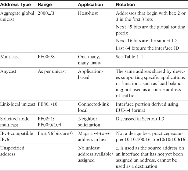
A special note must be made of IPv6 multicast addresses. Because there is no concept of a broadcast address in IPv6, multicast takes the place of all functions that would use broadcast in an IPv4 network.
As shown in Table 2a-1, an IPv6 multicast address always begins with FF as the first octet. The second octet specifies lifetime (permanent—0000 or temporary—0001) and scope:
0001 = Node
0010 = Link
0101 = Site
1000 = Organization
1110 = Global
Table 2a-2 shows several well-known IPv6 multicast group addresses and their functions.

IPv6 Address Allocation
To facilitate the administration of IPv6 addressing, a process called autoconfiguration was defined. An IPv6 host can configure its complete address or the interface ID portion of its address, depending on the method of autoconfiguration used:
![]() Stateful autoconfiguration: Assigns the entire 128-bit IPv6 address using DHCP.
Stateful autoconfiguration: Assigns the entire 128-bit IPv6 address using DHCP.
![]() Stateless autoconfiguration: Dynamic assignment of a 64-bit prefix to an interface. The remaining 64 bits of the interface ID are derived from the EUI-64 address format.
Stateless autoconfiguration: Dynamic assignment of a 64-bit prefix to an interface. The remaining 64 bits of the interface ID are derived from the EUI-64 address format.
With EUI-64, the interface ID is a locally configured globally unique value. Global uniqueness is ensured in Ethernet interfaces by the use of the MAC address of that interface, which is used with the IEEE EUI-64 standard. The following example illustrates how this is achieved:
Given the IPv6 prefix of 2001:128:1F:633 and a MAC address of 00:07:85:80:71:B8, the resulting EUI-64 address is
2001:128:1F:633:207:85FF:FE80:71B8/64
EUI-64 sets the seventh bit in the interface ID (universal/local scope set to global) and inserts a hex value of FFFE into the center of the MAC address to add the required 16 additional bits to the 48-bit MAC address to yield a 64-bit interface ID.
IPv6 Addressing Standards
The following standards are useful for further reading on IPv6 addressing:
![]() RFC 4291—IPv6 Addressing Architecture
RFC 4291—IPv6 Addressing Architecture
![]() RFC 3587—IPv6 Global Unicast Address Format
RFC 3587—IPv6 Global Unicast Address Format
![]() RFC 4862—IPv6 Stateless Address Autoconfiguration
RFC 4862—IPv6 Stateless Address Autoconfiguration
![]() RFC 4007—IPv6 Scoped Address Architecture
RFC 4007—IPv6 Scoped Address Architecture
Solution and Verification for Exercise 1.5: Cisco IOS Zone-Based Firewall with Support for Secure Group Tagging
Skills Tested
![]() Configuring Cisco ZFW with multi-zone application
Configuring Cisco ZFW with multi-zone application
![]() Defining firewall policy based on an understanding of traffic flows and network protocols in the network
Defining firewall policy based on an understanding of traffic flows and network protocols in the network
![]() Using secure group tags and a source identifier of interesting traffic to match
Using secure group tags and a source identifier of interesting traffic to match
Solution and Verification
When configuring ZFW, the Modular QoS CLI (MQC) style of syntax consisting of class maps, policy maps, and service policies is used with the inspect keyword. This command syntax is called Cisco Policy Language (CPL). Cisco IOS ZFW functionality is often referred to as ip inspect.
ZFW maps interface groupings to zones. Traffic passing between zones must be explicitly allowed. Zones are user-defined groups of interfaces. In addition, the addresses on the router itself form a special “self” zone. By default, traffic and protocols sourced from or destined to the self zone do not require explicit rules, although they can be applied to implement stateful firewalling or to explicitly deny flows between the self zone and the user-defined zones.
This question requires the administrator to have a clear understanding of the traffic traversing and terminating on R6. Traffic not explicitly allowed between user-defined zones is implicitly denied. ZFW will inspect at Layers 4 through 7 and track UDP and TCP connection state. IP protocols that cannot be inspected at Layer 4 or Layer 7 must be explicitly allowed between zones by using an access list; for example, Encapsulating Security Payload (ESP) traffic. DMVPN traffic is required to allow communication between hub and spokes, and ESP is encapsulated in UDP/4500 by virtue of NAT-T negotiation, which requires a firewall rule on R6.
R6 is a tunnel termination point for several virtual private network (VPN) tunnels, as well as being a Border Gateway Protocol (BGP) peer and Open Shortest Path First (OSPF) neighbor; all of these functions fall within the self zone, which in the exercise is supporting the default behavior of not requiring explicit ZFW policy to allow traffic to flow in and out of the self zone.
This exercise requires deep packet inspection (DPI) of HTTP, using the HTTP application inspection and control (AIC) engine, and the reset action must be used. A Layer 7 (DPI) policy map must be nested at the second level in a Layer 3 or Layer 4 inspect policy map; therefore, a Layer 7 policy map cannot be attached directly to a zone pair. You can specify the reset action only for TCP traffic.
ZFW also supports Security Group Tags (SGT) on specific platforms. In the case of the ISR G2 (used in this example), an SGT can be used to identify the source address of traffic within an ip inspect policy. The IP-to-SGT mappings are learned by R6 from SW2. These tags are then added to a class map to identify traffic sources of interest. SGTs will be propagated to R6 via SGT Exchange Protocol (SXP) and will be used as the source identifiers for the firewall match criteria.
To learn these mappings, R6 will take the role as an SXP local listener and peer with SW2 as the remote speaker as configured in Exercise 6.3.
For all verification syntax that follows:
![]() Required output appears in red
Required output appears in red
![]() Variable syntax appears in green
Variable syntax appears in green
This exercise required two user-defined zones. The output of the show zone security command will display each zone and its member interfaces. Note that the self zone, which is system-defined, will always be displayed in this output and contains no interfaces. All of the IP interfaces on the router are automatically made part of the self zone when ZFW is configured.
R6# show zone security
zone self
Description: System defined zone
zone outside
Member Interfaces:
Ethernet0/1
zone inside
Member Interfaces:
Ethernet0/0
Verification of the ZFW policy and its application on the router can be done for the most part using the show policy-map type inspect zone-pair sessions command. The names highlighted in green are user-defined names. The access control list (ACL) content itself is verified later in this section. Note the highlighted match-any and match-all usage. In the case of a single traffic match criteria in a class map or policy map, either match-all or match-any may be used. For multiple match criteria, match-all implies AND, match-any implies OR.
R6# show policy-map type inspect zone-pair sessions
policy exists on zp out-in
Zone-pair: out-in
Service-policy inspect : firewall-policy-in
Class-map: crypto (match-any)
Match: access-group 102
0 packets, 0 bytes
30 second rate 0 bps
Match: protocol isakmp
0 packets, 0 bytes
30 second rate 0 bps
Match: protocol gdoi
0 packets, 0 bytes
30 second rate 0 bps
Match: access-group 103
0 packets, 0 bytes
30 second rate 0 bps
Pass
0 packets, 0 bytes
Class-map: sgt4policy (match-all)
Match: class-map match-any sgt4
Match: security-group source tag 4
0 packets, 0 bytes
30 second rate 0 bps
Match: class-map match-any in-sgt-inspect
Match: protocol icmp
0 packets, 0 bytes
30 second rate 0 bps
Match: protocol udp
0 packets, 0 bytes
30 second rate 0 bps
Class-map: sgt5policy (match-all)
Match: class-map match-any sgt5
Match: security-group source tag 5
0 packets, 0 bytes
30 second rate 0 bps
Match: class-map match-any in-sgt-inspect
Match: protocol icmp
0 packets, 0 bytes
30 second rate 0 bps
Match: protocol udp
0 packets, 0 bytes
30 second rate 0 bps
Inspect
Class-map: in-inspect (match-any)
Match: protocol icmp
0 packets, 0 bytes
30 second rate 0 bps
Match: protocol telnet
0 packets, 0 bytes
30 second rate 0 bps
Match: protocol dns
0 packets, 0 bytes
30 second rate 0 bps
Match: protocol ntp
0 packets, 0 bytes
30 second rate 0 bps
Match: protocol radius
0 packets, 0 bytes
30 second rate 0 bps
Match: protocol tacacs
0 packets, 0 bytes
30 second rate 0 bps
Match: protocol http
0 packets, 0 bytes
30 second rate 0 bps
Match: protocol https
0 packets, 0 bytes
30 second rate 0 bps
Inspect
Class-map: class-default (match-any)
Match: any
Drop
0 packets, 0 bytes
policy exists on zp in-out
Zone-pair: in-out
Service-policy inspect : firewall-policy-out
Class-map: crypto (match-any)
Match: access-group 102
0 packets, 0 bytes
30 second rate 0 bps
Match: protocol isakmp
0 packets, 0 bytes
30 second rate 0 bps
Match: protocol gdoi
0 packets, 0 bytes
30 second rate 0 bps
Match: access-group 103
0 packets, 0 bytes
30 second rate 0 bps
Pass
0 packets, 0 bytes
Class-map: http (match-all)
Match: protocol http
Inspect
Class-map: out-inspect (match-any)
Match: access-group 101
0 packets, 0 bytes
30 second rate 0 bps
Inspect
Class-map: class-default (match-any)
Match: any
Drop
0 packets, 0 bytes
Verify ACLs are defined as follows:
R6# show access-list
Extended IP access list 101
10 permit ip any any
Extended IP access list 102
10 permit udp 10.50.0.0 0.0.255.255 10.50.0.0 0.0.255.255 eq non500-isakmp
20 permit esp 10.50.0.0 0.0.255.255 10.50.0.0 0.0.255.255
Extended IP access list 103
10 permit gre 10.50.0.0 0.0.255.255 10.50.0.0 0.0.255.255
The Layer 7 AIC engine for HTTP configuration may be verified using the following:
R6# show class-map type inspect http
Class Map type inspect http match-any httpDPI (id 2)
Match request port-misuse tunneling
R6# show policy-map type inspect http
Policy Map type inspect http resetportmisuse
Class httpDPI
Reset
Log
Support for SGTs as the source of traffic flows to be subject to ZFW inspection requires that R6 has knowledge of the mapping from an IP address to an SGT. Not all devices can natively use the tags added to packets by SGT-capable hardware. In this case, tags must be either manually defined or learned via SXP (covered in Lab 2, Exercises 6.2 and 6.3). If SXP is successfully configured between R6 (listener) and SW2 (speaker), the SGT tags 4 and 5 will appear in the output of show cts role-based sgt all. This is the preferred method for learning these dynamically created mappings because the IP addresses associated with the SGT values are DHCP issued and may not remain static.
R6# show cts role sgt all
Active IP-SGT Bindings Information
IP Address SGT Source
============================================
10.50.9.5 2 SXP
10.50.9.7 4 SXP
10.50.30.3 12 SXP
10.50.30.4 12 SXP
10.50.40.7 7 SXP
10.50.50.5 2 SXP
10.50.50.20 14 SXP
10.50.70.4 3 SXP
10.50.70.5 2 SXP
10.50.70.6 3 SXP
10.50.77.5 2 SXP
10.50.77.253 5 SXP
10.50.80.50 16 SXP
10.50.99.5 2 SXP
10.50.100.1 15 SXP
10.50.100.2 15 SXP
10.50.100.10 15 SXP
192.168.2.25 18 SXP
Configuration
R6
cts sxp enable
cts sxp connection peer 10.50.70.5 password none mode local listener
class-map type inspect match-any crypto
match access-group 102
match protocol isakmp
match protocol gdoi
match access-group 103
class-map type inspect match-any in-sgt-inspect
match protocol icmp
match protocol udp
class-map type inspect match-all http
match protocol http
class-map type inspect match-any out-inspect
match access-group 101
class-map type inspect http match-any httpDPI
match request port-misuse tunneling
class-map type inspect match-any sgt4
match security-group source tag 4
class-map type inspect match-all sgt4policy
match class-map sgt4
match class-map in-sgt-inspect
class-map type inspect match-any sgt5
match security-group source tag 5
class-map type inspect match-all sgt5policy
match class-map sgt5
match class-map in-sgt-inspect
class-map type inspect match-any in-inspect
match protocol icmp
match protocol telnet
match protocol dns
match protocol ntp
match protocol radius
match protocol tacacs
match protocol http
match protocol https!
!
policy-map type inspect http resetportmisuse
class type inspect http httpDPI
reset
!
policy-map type inspect firewall-policy-in
class type inspect crypto
pass
class type inspect sgt4policy
inspect
class type inspect sgt5policy
inspect
class type inspect in-inspect
inspect
class class-default
drop
!
policy-map type inspect firewall-policy-out
class type inspect crypto
pass
class type inspect http
inspect
service-policy http resetportmisuse
class type inspect out-inspect
inspect
class class-default
drop
!
zone security outside
zone security inside
zone-pair security out-in source outside destination inside
service-policy type inspect firewall-policy-in
zone-pair security in-out source inside destination outside
service-policy type inspect firewall-policy-out
!
interface Ethernet0/0
zone-member security inside
!
interface Ethernet0/1
zone-member security outside
access-list 101 permit ip any any
access-list 102 permit udp 10.50.0.0 0.0.255.255 10.50.0.0 0.0.255.255 eq
non500-isakmp
access-list 102 permit esp 10.50.0.0 0.0.255.255 10.50.0.0 0.0.255.255
access-list 103 permit gre 10.50.0.0 0.0.255.255 10.50.0.0 0.0.255.255
Tech Notes
The Cisco IOS Zone-Based Firewall is the successor to Context-Based Access Control (CBAC) and enables multiple router interfaces to be grouped into security zones. Configuration of ZFW involves three elements:
![]() Security Zone: A security zone is a group of interfaces to which a policy can be applied. By default, traffic flows freely between interfaces in the same zone, but traffic between zones is explicitly dropped. There is no concept of levels of security that dictate implicit behavior as with the Cisco ASA. The types of policies applied per zone dictate the level of security. All flows require a rule, even if it’s a simple pass ip any any. Flows between user-defined zones represent router transit traffic. Traffic sourced and destined to addresses on the router itself belongs to a system-defined zone known as the self zone. By default, traffic in and out of the self zone is not examined and flows freely.
Security Zone: A security zone is a group of interfaces to which a policy can be applied. By default, traffic flows freely between interfaces in the same zone, but traffic between zones is explicitly dropped. There is no concept of levels of security that dictate implicit behavior as with the Cisco ASA. The types of policies applied per zone dictate the level of security. All flows require a rule, even if it’s a simple pass ip any any. Flows between user-defined zones represent router transit traffic. Traffic sourced and destined to addresses on the router itself belongs to a system-defined zone known as the self zone. By default, traffic in and out of the self zone is not examined and flows freely.
![]() Zone Pair: A zone pair applies a unidirectional firewall policy between two zones. The zone pair specifies the source and destination zone and a traffic flow direction (for example, inside to outside or outside to inside). If traffic into and out of the self zone is to be processed by ZFW, the self zone must be specified as the source or destination zone in a zone pair; for example, self to outside.
Zone Pair: A zone pair applies a unidirectional firewall policy between two zones. The zone pair specifies the source and destination zone and a traffic flow direction (for example, inside to outside or outside to inside). If traffic into and out of the self zone is to be processed by ZFW, the self zone must be specified as the source or destination zone in a zone pair; for example, self to outside.
![]() Zone Policy: A zone policy defines traffic match criteria and the actions to be performed on it. The command syntax for ZFW is known as Cisco Policy Language (CPL), which is a form of MQC that introduces a special class map and policy map type inspect. Traffic that matches the interesting criteria is subject to the following actions: drop, pass, and inspect.
Zone Policy: A zone policy defines traffic match criteria and the actions to be performed on it. The command syntax for ZFW is known as Cisco Policy Language (CPL), which is a form of MQC that introduces a special class map and policy map type inspect. Traffic that matches the interesting criteria is subject to the following actions: drop, pass, and inspect.
![]() Drop: The default action for all traffic, as applied by the class class-default that terminates every inspect-type policy map. Other class maps within a policy map can also be configured to drop unwanted traffic. Traffic that is handled by the drop action is “silently” dropped (that is, no notification of the drop is sent to the relevant end host) by the ZFW, as opposed to an ACL’s behavior of sending an ICMP “host unreachable” message to the host that sent the denied traffic. The log option can be added with drop for syslog notification that traffic was dropped by the firewall.
Drop: The default action for all traffic, as applied by the class class-default that terminates every inspect-type policy map. Other class maps within a policy map can also be configured to drop unwanted traffic. Traffic that is handled by the drop action is “silently” dropped (that is, no notification of the drop is sent to the relevant end host) by the ZFW, as opposed to an ACL’s behavior of sending an ICMP “host unreachable” message to the host that sent the denied traffic. The log option can be added with drop for syslog notification that traffic was dropped by the firewall.
![]() Pass: Enables the router to forward traffic from one zone to another. The pass action does not track the state of connections or sessions within the traffic. Pass enables the traffic in only one direction. A corresponding policy must be applied to enable return traffic to pass in the opposite direction. The pass action is useful for protocols such as IPsec ESP, IPsec AH, ISAKMP, and other inherently secure protocols with predictable behavior. May be combined with the log option for syslog message generation.
Pass: Enables the router to forward traffic from one zone to another. The pass action does not track the state of connections or sessions within the traffic. Pass enables the traffic in only one direction. A corresponding policy must be applied to enable return traffic to pass in the opposite direction. The pass action is useful for protocols such as IPsec ESP, IPsec AH, ISAKMP, and other inherently secure protocols with predictable behavior. May be combined with the log option for syslog message generation.
![]() Inspect: The inspect action offers traffic selector (Layer 3), state-based (Layer 4), and application engine deep packet inspection (DPI) (Layer 7) traffic control. For example, if traffic from a private zone to an Internet zone is inspected, the router maintains connection or session information for TCP and UDP traffic. Therefore, the router permits return traffic sent from Internet-zone hosts in reply to private zone connection requests. Also, inspect can provide application inspection and control for certain service protocols that might carry vulnerable or sensitive application traffic. An audit trail can be applied with a parameter map to record connection/session start, stop, duration, the data volume transferred, and source and destination addresses.
Inspect: The inspect action offers traffic selector (Layer 3), state-based (Layer 4), and application engine deep packet inspection (DPI) (Layer 7) traffic control. For example, if traffic from a private zone to an Internet zone is inspected, the router maintains connection or session information for TCP and UDP traffic. Therefore, the router permits return traffic sent from Internet-zone hosts in reply to private zone connection requests. Also, inspect can provide application inspection and control for certain service protocols that might carry vulnerable or sensitive application traffic. An audit trail can be applied with a parameter map to record connection/session start, stop, duration, the data volume transferred, and source and destination addresses.
![]() Content Filter: Lets you configure HTTP content inspection (URL filtering) based on a WebFilter parameter map or a WebFilter policy map. This action is generally equivalent to a Web Filter rule; however, zone-based firewall rules support additional advanced options, such as HTTP DPI.
Content Filter: Lets you configure HTTP content inspection (URL filtering) based on a WebFilter parameter map or a WebFilter policy map. This action is generally equivalent to a Web Filter rule; however, zone-based firewall rules support additional advanced options, such as HTTP DPI.
Interesting traffic can be identified at various layers of the OSI model:
![]() Layer 3: Uses ACLs to identify specific flows. These can be used to identify IP protocols such as ESP and generic routing encapsulation (GRE), which are combined with the pass or drop actions because these encapsulated traffic flows cannot be inspected at Layer 4 or Layer 7. An ACL may also be combined with a Layer 4 protocol in a match-all class map for finer control.
Layer 3: Uses ACLs to identify specific flows. These can be used to identify IP protocols such as ESP and generic routing encapsulation (GRE), which are combined with the pass or drop actions because these encapsulated traffic flows cannot be inspected at Layer 4 or Layer 7. An ACL may also be combined with a Layer 4 protocol in a match-all class map for finer control.
Example:
Device(config)# class-map type inspect match-all c1
Device(config-cmap)# match access-group 101
Device(config-cmap)# match protocol http
Class maps can apply an ACL as one of the match criteria for policy application. If a class map’s only match criterion is an ACL, and the class map is associated with a policy map applying the inspect action, the router applies basic TCP or UDP inspection for all traffic allowed by the ACL as applicable, except that for which ZFW provides application-aware inspection.
If application-specific visibility into network activity is desired, you must configure inspection for services by application name (configure match protocol http, match protocol telnet, and so on).
![]() Layer 4: Defined using match protocol protocol in a class map and usually combined with an inspect action. If multiple protocols are to be inspected under one class map, care must be taken with match-all versus match-any types.
Layer 4: Defined using match protocol protocol in a class map and usually combined with an inspect action. If multiple protocols are to be inspected under one class map, care must be taken with match-all versus match-any types.
Example:
If the goal is to match ICMP or HTTP traffic, the following will not match any traffic because a packet cannot be both an HTTP and ICMP packet:
Device(config)# class-map type inspect match-all c1
Device(config-cmap)# match protocol http
Device(config-cmap)# match protocol icmp
The correct configuration is
Device(config)# class-map type inspect match-any c1
Device(config-cmap)# match protocol http
Device(config-cmap)# match protocol icmp
![]() Layer 7: DPI functionality is delivered through Layer 7 class maps and policy maps for specific applications using AIC engines. The list of support applications can vary with the version of Cisco IOS in use.
Layer 7: DPI functionality is delivered through Layer 7 class maps and policy maps for specific applications using AIC engines. The list of support applications can vary with the version of Cisco IOS in use.
Device(config)# class-map type inspect ?
aol Configure Firewall class-map for IM-AOL protocol
edonkey eDonkey
fasttrack FastTrack Traffic - KaZaA, Morpheus, Grokster...
gnutella Gnutella Version2 Traffic - BearShare, Shareeza, Morpheus ...
h323 Configure Firewall class-map for H323 protocol
http Configure Firewall class-map for HTTP protocol
icq Configure Firewall class-map for IM-ICQ protocol
imap Configure Firewall class-map for IMAP protocol
kazaa2 Kazaa Version 2
match-all Logical-AND all matching statements under this classmap
match-any Logical-OR all matching statements under this classmap
msnmsgr Configure Firewall class-map for IM-MSN protocol
pop3 Configure Firewall class-map for POP3 protocol
sip Configure Firewall class-map for SIP protocol
smtp Configure Firewall class-map for SMTP protocol
sunrpc Configure Firewall class-map for RPC protocol
winmsgr Configure Firewall class-map for IM-WINMSGR protocol
ymsgr Configure Firewall class-map for IM-YAHOO protocol
Separate Layer 4 class maps are defined for HTTP, Yahoo Messenger, and eDonkey because Layer 7 application inspection policy for these protocols must be applied to their respective Layer 4 policy maps as in the exercise; for example:
Define the Layer 4 match criteria:
R6(config)# class-map type inspect match-all http
R6(config-cmap)# match protocol http
Define the DPI requirements:
R6(config)# class-map type inspect http match-any httpDPI
R6(config-cmap)# match request port-misuse ?
any Any type of port misuse
im Instant Messaging
p2p Peer-to-peer application
tunneling Tunneling applications
R6(config-cmap)# match request port-misuse tunneling
R6(config-cmap)# exit
Define the actions to be performed on the DPI match criteria:
R6(config)# policy-map type inspect http resetportmisuse
R6(config-pmap)# class type inspect http httpDPI
R6(config-pmap-c)# reset
The final policy will identify HTTP traffic to be DPI inspected using the HTTP AIC engine to check for specific conditions.
R6(config)# policy-map type inspect firewall-policy
R6(config-pmap)# class type inspect remotes2
R6(config-pmap-c)# inspect
R6(config-pmap-c)# service-policy http resetportmisuse
Section 2: Intrusion Prevention and Content Security
This section covers more advanced tasks applicable to the Intrusion Prevention Sensor (IPS) and Web Services Appliance (WSA). Configuring custom signatures and defining event action overrides are important signature tuning techniques applicable to the Cisco IPS. In Lab 1, you initialized the WSA and configured Web Cache Communication Protocol (WCCP) Transparent proxy service using the ASA as the WCCP server. In this section, you add user authentication to this scenario, and then incorporate guest services.
Solution and Verification for Exercise 2.1: Configuring Custom Signatures on the Cisco IPS Sensor
Skills Tested
![]() IPS sensor custom signature configuration
IPS sensor custom signature configuration
![]() Understanding the components of attacks and vulnerabilities
Understanding the components of attacks and vulnerabilities
![]() Defining event actions and overrides and manipulating risk ratings
Defining event actions and overrides and manipulating risk ratings
![]() Applying signatures and event action rules to virtual sensors
Applying signatures and event action rules to virtual sensors
![]() Verifying whether signatures are working correctly with real-time traffic
Verifying whether signatures are working correctly with real-time traffic
![]() Understanding the functions and benefits of IPS sensor signature engines
Understanding the functions and benefits of IPS sensor signature engines
Solution and Verification
Implementing custom signatures requires a good understanding of the threats and vulnerabilities that impact specific network deployments. Signatures are customized based on the priorities of the network and go above and beyond the signature database that covers all types of well-known attacks. The purpose of this exercise is to illustrate the options available to the administrator in terms of signature engine selection, event actions, and alert severities and formulating signature trigger criteria. This criterion varies according to the requirements of the signature engine selected.
Signatures can also be customized in terms of how they are applied with respect to risk ratings. Although a trigger might be the same, the actions taken can differ depending on the risk to the hosts or subnets impacted. Event action rule sets are a way to override the general rules associated with a signature depending on the risk criteria. They are also an efficient way of applying a blanket policy to the groups of signatures assigned to a virtual sensor, eliminating the need to individually define actions and alerts.
Various show command outputs can provide custom signature configuration verification, including those that show events in real time.
For all verification syntax that follows:
![]() Required output appears in red
Required output appears in red
![]() Required tasks appear in indigo
Required tasks appear in indigo
![]() Variable syntax appears in green
Variable syntax appears in green
Custom Signature to Track OSPF TTL
All OSPF packets seen by vs0 should have a time to live (TTL) of 255. Vs0 is sensing traffic in OSPF Area 0 from the perspective of SW2. All neighbors are adjacent to SW2. In a real-world situation, the signature would trigger for any OSPF packet that has a TTL value less than the specific value.
The show events alert severity-level command displays a trigger packet in real time. In the following output, 0xFF is the TTL value 255 and 0x59 is IP protocol 89 (OSPF):
IPS# show events alert medium
evIdsAlert: eventId=1374345338767123448 severity=medium vendor=Cisco
originator:
hostId: ips
appName: sensorApp
appInstanceId: 414
time: 2013/08/27 21:42:25 2013/08/27 21:42:25 UTC
signature: description=OSPF TTL id=64000 created=20000101 type=other
version=custom
subsigId: 0
sigDetails: My Sig Info
marsCategory: Info/Misc
interfaceGroup: vs0
vlan: 70
participants:
attacker:
addr: locality=OUT 10.50.70.5
target:
addr: locality=OUT 224.0.0.5
os: idSource=unknown relevance=relevant type=unknown
triggerPacket:
000000 01 00 5E 00 00 05 C4 64 13 FC 2A 44 81 00 C0 32 ..^....d..*D...2
000010 08 00 45 C0 00 50 E0 C6 00 00 FF 59 A9 91 0A 32 ..E..P.....Y...2
000020 46 05 E0 00 00 05 02 01 00 30 02 02 02 02 00 00 F........0......
000030 00 00 3C 1B 00 00 00 00 00 00 00 00 00 00 FF FF ..<.............
000040 FF 00 00 0A 12 01 00 00 00 28 0A 32 46 06 0A 32 .........(.2F..2
000050 46 05 06 06 06 06 FF F6 00 03 00 01 00 04 00 00 F...............
000060 00 01 ..
riskRatingValue: attackRelevanceRating=relevant targetValueRating=medium 66
threatRatingValue: 66
interface: ge0_2
protocol: IP protocol 89
Custom Signature to Identify and Deny Large ICMP Packets
This signature is verified by sending an ICMP packet within the specified trigger range. The verbose alerts will display the packet dump. Values highlighted in green are the fragment-specific bits.
R6# ping 10.50.40.7 size 1500
IPS# show event alert high
evIdsAlert: eventId=1374345338767123402 severity=high vendor=Cisco
originator:
hostId: ips
appName: sensorApp
appInstanceId: 414
time: 2013/08/27 21:23:46 2013/08/27 21:23:46 UTC
signature: description=Large ICMP Attack id=65000 created=20000101 type=other
version=custom
subsigId: 0
sigDetails: My Sig Info
marsCategory: Info/Misc
interfaceGroup: vs0
vlan: 50
participants:
attacker:
addr: locality=OUT 10.50.70.6
target:
addr: locality=OUT 10.50.40.7
os: idSource=unknown relevance=relevant type=unknown
triggerPacket:
000000 00 15 C6 95 C6 46 C4 64 13 FC 2A 43 81 00 00 46 .....F.d..*C...F
000010 08 00 45 00 05 DC 00 A6 00 00 FE 01 34 0A 0A 32 ..E.........4..2
000020 46 06 0A 32 28 07 08 00 C0 2E 00 0A 00 01 00 00 F..2(...........
000030 00 00 0F B9 E7 F5 AB CD AB CD AB CD AB CD AB CD ................
riskRatingValue: attackRelevanceRating=relevant targetValueRating=medium 85
threatRatingValue: 85
interface: ge0_2
protocol: icmp
Custom Signature to Identify and Deny an ICMP Flood Attack
To verify the flood signature and event action rules, first ping the host that has been designated as mission critical. Note that initially the ping will succeed until the configured threshold is exceeded, which triggers the signature event actions. This host was assigned a target value rating of 100, which will meet the risk rating criteria defined in the event-action rules, forcing the event-action overrides as shown under actions in the following output:
R6# ping 192.168.2.25 rep 200
Type escape sequence to abort.
Sending 2000, 100-byte ICMP Echos to 192.168.2.25, timeout is 2 seconds:
!!!!!!!!!!!!!!!!!!!!!!!!!!!!!!!!!!!!!!!!!!!!!!!!!!!!!!!!!!!!!!!!!!!!!!
!!!!!!!!!!!!!!!!!!!!!!!!!!!!!.........................................
..
IPS# show events alert high
evIdsAlert: eventId=1374345338767164950 severity=high vendor=Cisco
originator:
hostId: ips
appName: sensorApp
appInstanceId: 414
time: 2013/09/21 01:34:31 2013/09/21 01:34:31 UTC
signature: description=My Sig id=62000 created=20000101 type=other
version=custom
subsigId: 0
sigDetails: My Sig Info
marsCategory: Info/Misc
interfaceGroup: vs1
vlan: 0
participants:
attacker:
addr: locality=OUT 10.50.80.6
target:
addr: locality=OUT 192.168.2.25
os: idSource=learned relevance=relevant type=windows-nt-2k-xp
actions:
logPacketsActivated: true
deniedPacket: true
deniedAttacker: true
logAttackerPacketsActivated: true
ipLogIds:
ipLogId: 1701736978
riskRatingValue: attackRelevanceRating=relevant targetValueRating=mission-
critical 100
threatRatingValue: 55
interface: ge0_0
protocol: icmp
Sending a ping to a host not defined as mission critical will not meet the risk rating range of 90–100, so event-action overrides are not applied. In this case, only those actions defined under the signature definition itself are taken.
R3# ping 192.168.2.50 rep 100
Type escape sequence to abort.
Sending 100, 100-byte ICMP Echos to 192.168.2.50, timeout is 2 seconds:
!!!!!!!!!!!!!!!!!!!!!!!!!!!!!!!!!!!!!!!!!!!!!!!!!!!!!!!!!!!!!!!!!!!!!!
!!!!!!!!!!!!!!!!!!!!!!!!!!!!!.
IPS# show events alert high
evIdsAlert: eventId=1374345338767164960 severity=high vendor=Cisco
originator:
hostId: ips
appName: sensorApp
appInstanceId: 414
time: 2013/09/21 01:40:50 2013/09/21 01:40:50 UTC
signature: description=My Sig id=62000 created=20000101 type=other
version=custom
subsigId: 0
sigDetails: My Sig Info
marsCategory: Info/Misc
interfaceGroup: vs1
vlan: 0
participants:
attacker:
addr: locality=OUT 10.50.30.3
target:
addr: locality=OUT 192.168.2.50
os: idSource=learned relevance=relevant type=bsd
actions:
deniedPacket: true
riskRatingValue: attackRelevanceRating=relevant targetValueRating=medium 85
threatRatingValue: 50
interface: ge0_0
protocol: icmp
Viewing statistics on a virtual sensor is a good way to see a report of traffic that has been mapped to signature triggers and what actions have been taken in response to that traffic. This output is very verbose, so only the information relevant to this question is shown.
IPS# show stat virtual-sensor vs1
Statistics for Virtual Sensor vs1
Name of current Signature-Defintion instance = sig1
Name of current Event-Action-Rules instance = rules1
.........
Denied Address Information
Number of Active Denied Attackers = 1
Number of Denied Attackers Inserted = 1
Number of Denied Attacker Victim Pairs Inserted = 0
Number of Denied Attacker Service Pairs Inserted = 0
Number of Denied Attackers Total Hits = 439
Number of times max-denied-attackers limited creation of new entry = 0
Number of exec Clear commands during uptime = 0
Denied Attackers and hit count for each.
10.50.80.6 = 439
Denied Attackers with percent denied and hit count for each
Attacker Address Victim Address Port Protocol Requested Percentage
Actual Percentage Hit Count Reputation Action
10.50.80.6 100 100
439 false
Actions Performed
deny-attacker-inline = 0
deny-attacker-victim-pair-inline = 0
deny-attacker-service-pair-inline = 0
deny-connection-inline = 0
deny-packet-inline = 48
modify-packet-inline = 1588
log-attacker-packets = 20
log-pair-packets = 0
log-victim-packets = 0
produce-alert = 37
produce-verbose-alert = 2
request-block-connection = 0
request-block-host = 0
request-snmp-trap = 0
Configuration
service event-action-rules rules1
overrides deny-attacker-inline
override-item-status Enabled
risk-rating-range 90-100
exit
overrides log-attacker-packets
override-item-status Enabled
risk-rating-range 90-100
exit
overrides produce-alert
override-item-status Enabled
exit
target-value mission-critical target-address 192.168.2.25
exit
service signature-definition sig0
signatures 64000 0
alert-severity medium
sig-description
sig-name OSPF TTL
exit
engine atomic-ip
event-action produce-verbose-alert
specify-l4-protocol yes
l4-protocol other-protocol
other-ip-protocol-id 89
exit
exit
specify-ip-ttl yes
ip-ttl 255
exit
exit
status
enabled true
exit
exit
signatures 65000 0
alert-severity high
sig-description
sig-name Large ICMP Attack
exit
engine atomic-ip
event-action produce-verbose-alert
specify-l4-protocol yes
l4-protocol icmp
exit
exit
specify-ip-payload-length yes
ip-payload-length 1000-5000
exit
specify-ip-addr-options yes
ip-addr-options rfc-1918-address
exit
exit
status
enabled true
exit
exit
exit
! ------------------------------
service signature-definition sig1
signatures 62000 0
alert-severity high
engine flood-host
event-action produce-alert|deny-packet-inline
rate 100
protocol icmp
icmp-type 8
exit
exit
status
enabled true
exit
exit
exit
service analysis-engine
virtual-sensor vs0
physical-interface GigabitEthernet0/2 subinterface-number 1
exit
virtual-sensor vs1
signature-definition sig1
event-action-rules rules1
logical-interface ipair
exit
virtual-sensor vs2
physical-interface GigabitEthernet0/3
exit
exit
Tech Notes
Risk Ratings
A risk rating (RR) is a value between 0 and 100 that represents a level of risk associated with a particular event on the network. It is configured on a per-signature basis using the attack severity rating and the signature fidelity rating, and on a per-server basis using the target value rating. The risk rating is calculated from several components, some of which are configured, some collected, and some derived. The risk rating is associated with alerts, not signatures.
Risk ratings are used to prioritize alerts. The following values are used to calculate the risk rating for a particular event:
![]() Signature fidelity rating (SFR): A weight associated with how well this signature might perform in the absence of specific knowledge of the target. The signature fidelity rating is configured per signature and indicates how accurately the signature detects the event or condition it describes.
Signature fidelity rating (SFR): A weight associated with how well this signature might perform in the absence of specific knowledge of the target. The signature fidelity rating is configured per signature and indicates how accurately the signature detects the event or condition it describes.
![]() Attack severity rating (ASR): A weight associated with the severity of a successful exploit of the vulnerability.
Attack severity rating (ASR): A weight associated with the severity of a successful exploit of the vulnerability.
![]() Target value rating (TVR): A weight associated with the perceived value of the target.
Target value rating (TVR): A weight associated with the perceived value of the target.
![]() Attack relevance rating (ARR): A weight associated with the relevancy of the targeted operating system.
Attack relevance rating (ARR): A weight associated with the relevancy of the targeted operating system.
![]() Promiscuous delta (PD): A weight associated with the promiscuous delta, which can be subtracted from the overall risk rating in promiscuous mode. Promiscuous delta is in the range of 0 to 30 and is configured per signature. If the trigger packet is not inline, the promiscuous delta is subtracted from the rating.
Promiscuous delta (PD): A weight associated with the promiscuous delta, which can be subtracted from the overall risk rating in promiscuous mode. Promiscuous delta is in the range of 0 to 30 and is configured per signature. If the trigger packet is not inline, the promiscuous delta is subtracted from the rating.
![]() Watch list rating (WLR): A weight associated with the CSA MC watch list in the range of 0 to 100. CSA MC only uses the range 0 to 35.
Watch list rating (WLR): A weight associated with the CSA MC watch list in the range of 0 to 100. CSA MC only uses the range 0 to 35.
The risk rating formula is as follows:
Understanding Threat Rating
Threat rating is risk rating that has been lowered by event actions that have been taken. Non-logging event actions have a threat rating adjustment. The largest threat rating from all the event actions taken is subtracted from the risk rating.
The event actions have the following threat ratings:
![]() Deny attacker inline: 45
Deny attacker inline: 45
![]() Deny attacker victim pair inline: 40
Deny attacker victim pair inline: 40
![]() Deny attacker service pair inline: 40
Deny attacker service pair inline: 40
![]() Deny connection inline: 35
Deny connection inline: 35
![]() Deny packet inline: 35
Deny packet inline: 35
![]() Modify packet inline: 35
Modify packet inline: 35
![]() Request block connection: 20
Request block connection: 20
![]() Reset TCP connection: 20
Reset TCP connection: 20
![]() Request rate limit: 20
Request rate limit: 20
Solution and Verification for Exercise 2.2: Enable Support for HTTPS on the Cisco WSA
Skills Tested
![]() WSA HTTPS proxy configuration
WSA HTTPS proxy configuration
![]() Configuring HTTP Secure Server on a Cisco IOS Router
Configuring HTTP Secure Server on a Cisco IOS Router
Solution and Verification
The configuration of WSA is completed using the GUI. To verify your solution, you will need to follow the steps that follow and compare your outputs.
For all verification syntax that follows:
![]() Required output appears in red
Required output appears in red
![]() Required tasks appear in indigo
Required tasks appear in indigo
Verify whether the HTTPS server is enabled and ready to accept connections.
R4# show ip http server secure status
HTTP secure server status: Enabled
HTTP secure server port: 443
HTTP secure server ciphersuite: 3des-ede-cbc-sha des-cbc-sha rc4-128-md5
rc4-128-sha
HTTP secure server client authentication: Disabled
HTTP secure server trustpoint:
HTTP secure server active session modules: ALL
Verify whether the WSA has generated its self-signed certificate under HTTP Proxy settings, as shown in Figure 2a-1.
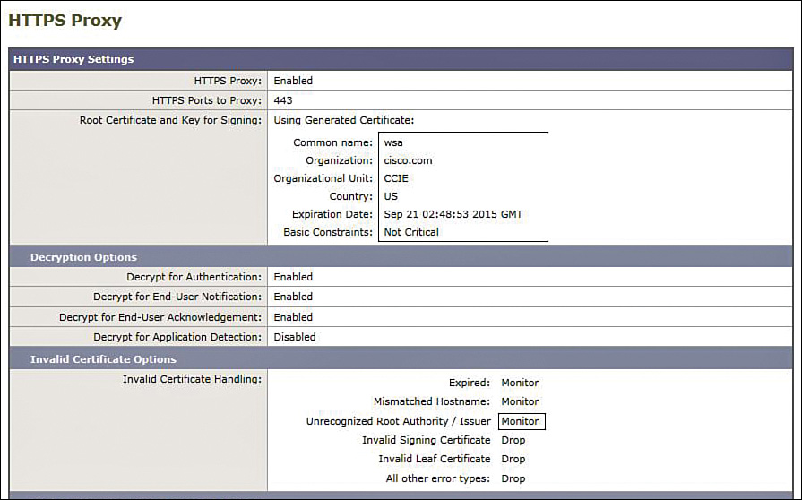
If there is an issue with the certificate timestamp, or the Invalid Certificate Handling > Unrecognized Root Authority/Issuer option was not set from Drop to Monitor, you will encounter the error shown in Figure 2a-2 when connecting to R4.

R4# sho ip http server history (note this must be completed after attempting a connection from a Test-PC using https://10.50.30.4 otherwise the history may be blank).
R4# show ip http server history
HTTP server history:
local-ipaddress:port remote-ipaddress:port in-bytes out-bytes end-time
10.50.30.4:443 192.168.2.50:28325 375 192 05:27:35
10.50.30.4:443 192.168.2.50:19583 371 2069 05:27:48
10.50.30.4:443 192.168.2.50:35418 324 137 05:27:48
10.50.30.4:443 192.168.2.50:50014 417 6043 05:29:08
10.50.30.4:443 192.168.2.50:55682 324 137 05:29:08
Configuration
R4 HTTPS Server
ip http secure-server
WSA
See Figure 2a-1
Solution and Verification for Exercise 2.3: Enable User Authentication for Transparent Proxy Using LDAP
Skills Tested
![]() Configuring user authentication for transparently redirected traffic on the Cisco WSA using LDAP
Configuring user authentication for transparently redirected traffic on the Cisco WSA using LDAP
![]() Creating users on an Active Directory server
Creating users on an Active Directory server
![]() Understanding how surrogate types impact user authentication
Understanding how surrogate types impact user authentication
Solution and Verification
The configuration of the WSA is completed using the GUI. To verify your solution, you will need to follow these steps and compare your outputs:
Step 1. Add a user, ccie, to the Active Directory server on 192.168.2.25, as shown in Figure 2a-3. These credentials will be referenced by the WSA during user authentication.

Step 2. Define an authentication realm using the information provided in Table 2-11 in Exercise 2-3 in Lab 2. After you configure the parameters, select the Start Test button at the bottom of the screen to verify whether you have connectivity with the AD server using LDAP and that your user credentials are correctly defined and accessed, as shown in Figure 2a-4.

Step 3. Ensure that your global authentication settings include enabling credential encryption, as shown in Figure 2a-5.
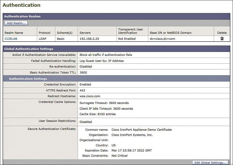
Step 4. Configure an authentication identity that outlines the policy to be applied to users authenticating via the CCIELAB realm defined in Step 2, as shown in Figure 2a-6.
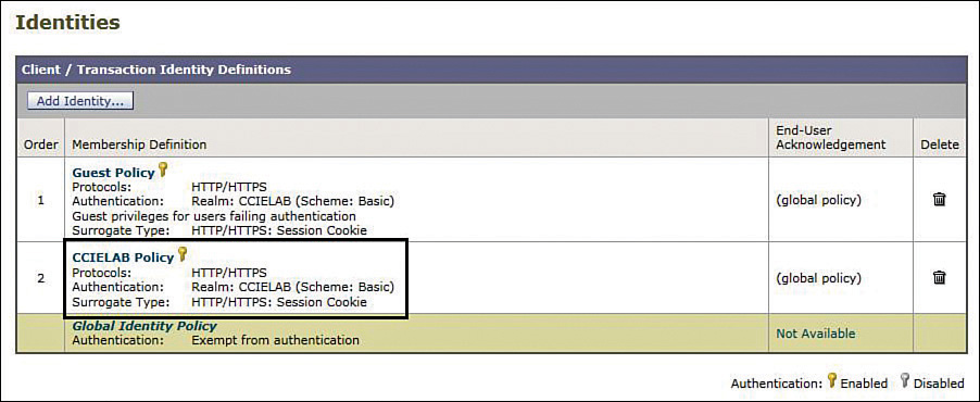
Step 5. To verify the solution, use the Test-PC browser to connect to any HTTP server in the network, and you should receive a prompt from the WSA for username/password credentials as shown in Figure 2a-7.

Step 6. Depending on the site chosen for your initial connection, you will have to enter a username/password for cut-through proxy authentication (for sites behind ASA2). If you wish to reauthenticate, close and reopen your browser. Using session cookies as the surrogate type means that the credentials used to authenticate initially will be applicable for all HTTP/HTTPS connections launched from the browser. Closing and reopening the browser clears the session cookie.
You may also check the user logs on the WSA to verify your connection history, as shown in Figure 2a-8.
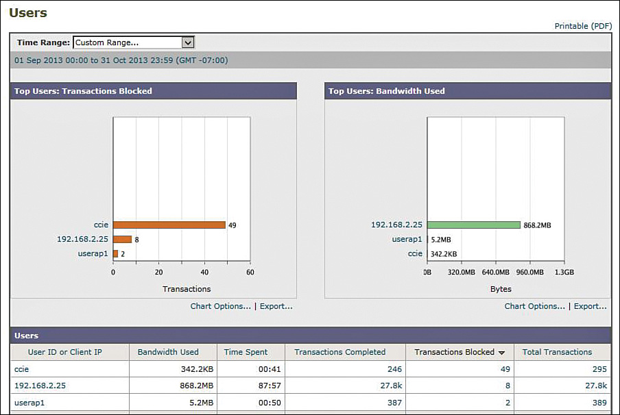
Solution and Verification for Exercise 2.4: Guest User Support on the Cisco WSA
Skills Tested
![]() Configuring a guest user identity with no authentication
Configuring a guest user identity with no authentication
![]() Defining and applying guest access policies
Defining and applying guest access policies
Solution and Verification
The configuration of WSA is completed using the GUI. To verify your solution, you will need to follow the steps outlined later, and compare your outputs.
For all verification syntax that follows:
![]() Required tasks appear in indigo
Required tasks appear in indigo
To verify your solution, close the browser on the Test-PC. Reopen the browser and connect to http://10.50.50.5. The WSA will prompt for username/password; enter guest. This will fail authentication but grant guest access. You should be able to connect to the SW2 website.
HTTP server history:
local-ipaddress:port remote-ipaddress:port in-bytes out-bytes end-time
10.50.50.5:80 192.168.2.50:64008 3547 251686 19:55:45 04/23
10.50.50.5:80 192.168.2.50:9612 4118 270121 19:55:45 04/23
Next, connect to any other 10.50.0.0 HTTP server. The connection should be blocked and a notification displayed as shown in Figure 2a-9.

WSA Configuration
Define a guest identity and an enforceable authentication policy as shown in Figure 2a-10.

Create a custom URL category that is applied to users satisfying the authentication policy criteria defined earlier; that is, 10.50.50.5/32. Also, define a URL category explicitly denying access to all other resources on 10.50.0.0/16 to guests. Ensure that your policies are applied in the correct order, as shown in Figure 2a-11.
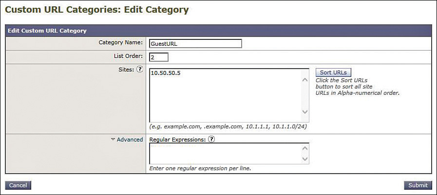
The access policy for guests will summarize the resource privileges granted to guest users as shown in Figure 2a-12. Because guests do not need to pass authentication, privileges are said to apply to those users failing authentication.
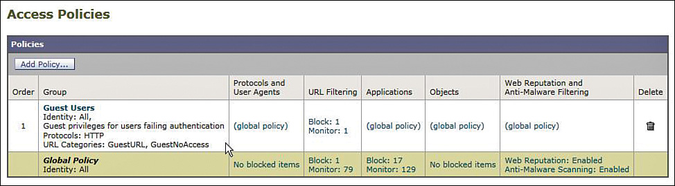
Section 3: Secure Access
This section presents some more-complex solutions for secure network access. The legacy remote access VPNs using IKEv1 in Lab 1 have been replaced with FlexVPN using IKEv2. In one exercise, we look at site-to-site remote access using RADIUS tunnel attributes and Cisco Secure ACS to provide the IKEv2 preshared key. Another FlexVPN scenario involves remote access client to server, which is the new version of EZVPN that uses IKEv2 for security association (SA) negotiation and remote attribute distribution (config mode). This section also covers the use of IPv6 with IPsec, IKEv1 using RSA signatures and dynamic routing over VTIs, SSL VPNs using both client and clientless connections terminating on the Cisco ASA, and GETVPN deployed with multicast rekeying.
Solution and Verification for Exercise 3.1: Configure and Troubleshoot IPsec Static VTI with IPv6
Skills Tested
![]() Configuring static IPsec VTIs for IPv6 traffic
Configuring static IPsec VTIs for IPv6 traffic
![]() Configuring Public Key Infrastructure (PKI) trustpoints and enrolling end entities with the Cisco Certificate Authority (CA) Server
Configuring Public Key Infrastructure (PKI) trustpoints and enrolling end entities with the Cisco Certificate Authority (CA) Server
![]() Deploying certificate maps with isakmp profiles
Deploying certificate maps with isakmp profiles
![]() Verifying IPv6 routing using EIGRPv6
Verifying IPv6 routing using EIGRPv6
![]() Troubleshooting IPsec VPNs
Troubleshooting IPsec VPNs
Solution and Verification
This exercise has several components:
![]() Certificates: Trustpoints, enrollment, cert maps
Certificates: Trustpoints, enrollment, cert maps
![]() IPsec static VTIs: IPv6
IPsec static VTIs: IPv6
![]() Routing: Verifying EIGRPv6
Routing: Verifying EIGRPv6
![]() Cisco ASA: Allowing access through ASA2 for traffic sourced from the DMZ interface and destined to the inside interface
Cisco ASA: Allowing access through ASA2 for traffic sourced from the DMZ interface and destined to the inside interface
The verification of this solution will follow an ideal ordering of the necessary tasks.
As specified in the question notes, Lab 2 Exercise 1.4 must be completed first. Unless the inside and DMZ interfaces of ASA2 are configured for IPv6, the IPsec VPN will not be established.
For all verification syntax that follows:
![]() Required output appears in red
Required output appears in red
![]() Required tasks appear in indigo
Required tasks appear in indigo
![]() Variable syntax appears in green
Variable syntax appears in green
Verify that ASA2 is configured to allow IPv6 traffic between the DMZ and inside interfaces:
ASA2# show ipv6 access-list
ipv6 access-list vpn line 1 permit esp 2001:DB9:30::4/64 2001:DB8:40::7/64
ipv6 access-list vpn line 3 permit udp 2001:DB9:30::4/64 2001:DB8:40::7/64 eq
isakmp
Ensure that R7 and R4 have a common, accurate time source; for example, add NTP server 10.50.70.6.
Define the PKI trustpoint on R4 and R7. Note that if Lab 2 Exercise 5.4 has been completed, the HTTP port number will be 8080; if not, the default port 80 is used.
crypto pki trustpoint ciscoca
enrollment retry count 5
enrollment retry period 3
enrollment url http://10.50.100.1:8080
revocation-check none
Generate RSA keys on each router:
R7(config)# crypto key gen rsa
Specify a modulus, this lab question uses 1024 bits.
Verify whether the key has been created; it will be used during end entity enrollment:
R7# show crypto key mypubkey rsa
% Key pair was generated at: 12:17:36 PST Sep 28 2013
Key name: R7.cisco.com
Key type: RSA KEYS
Storage Device: private-config
Usage: General Purpose Key
Key is not exportable.
Key Data:
30819F30 0D06092A 864886F7 0D010101 05000381 8D003081 89028181 00D495EA
395B6FDF 58DEB196 A46E8AC8 1336D428 5D450B4B 53695EC1 43DAF2FA 219689D7
5AB9245E B08D2958 B9F18189 B92A0FF1 EBD47E7B F5ED8D59 0C193191 5D25FCD2
DC45F474 675598F4 F24EF34F 68397297 D270BC5F 6C554876 AC7A39F5 6DCD42D6
F98D59CE CE189BFE 2C027C77 39F7ED96 784779E3 3A7EF457 F3DDB6BF 1F020301 0001
Obtain and authenticate the CA certificate, and then enroll the end entities (R4 and R7) with the CA ciscoca:
R4(config)# crypto pki authenticate ciscoca
Certificate has the following attributes:
Fingerprint MD5: 1F5A02E4 C2C8230A 56FC15BB CBDFBEF6
Fingerprint SHA1: 99D5D0AA 928B4DD8 7D9E6D98 B3831F1D 796C6A71
% Do you accept this certificate? [yes/no]: yes
R4(config)# crypto pki enroll ciscoca
%
% Start certificate enrollment ..
% Create a challenge password. You will need to verbally provide this
password to the CA Administrator in order to revoke your certificate.
For security reasons your password will not be saved in the configuration.
Please make a note of it.
Password: cisco
Re-enter password: cisco
% The subject name in the certificate will include: R4.cisco.com
% Include the router serial number in the subject name? [yes/no]: no
% Include an IP address in the subject name? [no]: no
Request certificate from CA? [yes/no]: yes
% Certificate request sent to Certificate Authority
% The 'show crypto pki certificate verbose ciscoca' command will show the
fingerprint.
R4(config)#
*Sep 29 01:17:00.529: CRYPTO_PKI: Certificate Request Fingerprint MD5: AC5647CD
4607D9DC 3819945F 12535ACC
*Sep 29 01:17:00.529: CRYPTO_PKI: Certificate Request Fingerprint SHA1: E01B51B5
B5F301AC 64B298FF D022E769 DA27D496
R4(config)#
*Sep 29 01:17:00.611: %PKI-6-CERTRET: Certificate received from Certificate
Authority
Verify receipt of the CA and end entity certificates. Ensure that the certificate validity dates and times are synchronized with the clock time on R4 and R7. If the certificate has not yet become valid due to a time issue, the IKE negotiation will fail; for example, ntp server 10.50.70.6.
R4# show cry pki certificates
Certificate
Status: Available
Certificate Serial Number (hex): 02
Certificate Usage: General Purpose
Issuer:
cn=ciscoca.cisco.com L=cisco C=US
Subject:
Name: R4.cisco.com
hostname=R4.cisco.com
Validity Date:
start date: 17:17:00 PST Sep 28 2013
end date: 17:17:00 PST Apr 16 2014
Associated Trustpoints: ciscoca
Storage: nvram:ciscocacisco#2.cer
CA Certificate
Status: Available
Certificate Serial Number (hex): 01
Certificate Usage: Signature
Issuer:
cn=ciscoca.cisco.com L=cisco C=US
Subject:
cn=ciscoca.cisco.com L=cisco C=US
Validity Date:
start date: 13:19:37 PST Aug 17 2013
end date: 13:19:37 PST Aug 17 2014
Associated Trustpoints: ciscoca
Storage: nvram:ciscocacisco#1CA.cer![]()
R7# show cry pki certificates
Certificate
Status: Available
Certificate Serial Number (hex): 0A
Certificate Usage: General Purpose
Issuer:
cn=ciscoca.cisco.com L=cisco C=US
Subject:
Name: R7.cisco.com
hostname=R7.cisco.com
Validity Date:
start date: 18:39:45 PST Sep 28 2013
end date: 18:39:45 PST Apr 16 2014
Associated Trustpoints: ciscoca
Storage: nvram:ciscocacisco#A.cer
CA Certificate
Status: Available
Certificate Serial Number (hex): 01
Certificate Usage: Signature
Issuer:
cn=ciscoca.cisco.com L=cisco C=US
Subject:
cn=ciscoca.cisco.com L=cisco C=US
Validity Date:
start date: 13:19:37 PST Aug 17 2013
end date: 13:19:37 PST Aug 17 2014
Associated Trustpoints: ciscoca
Storage: nvram:ciscocacisco#1CA.cer
Complete the configurations on R4 and R7, and verify whether the VPN tunnel has been established. This task requires some troubleshooting. The configuration section of this exercise highlights the missing configuration commands required to successfully bring up the static VTI.
R7# show crypto session
Interface: Tunnel2
Profile: ipv6
Session status: UP-ACTIVE
Peer: 2001:DB9:30::4 port 500
IKEv1 SA: local 2001:DB8:40::7/500
remote 2001:DB9:30::4/500 Active
IPSEC FLOW: permit ipv6 ::/0 ::/0
Active SAs: 2, origin: crypto map![]()
R4# show crypto session
Interface: Tunnel2
Profile: ipv6
Session status: UP-ACTIVE
Peer: 2001:DB8:40::7 port 500
IKEv1 SA: local 2001:DB9:30::4/500
remote 2001:DB8:40::7/500 Active
IPSEC FLOW: permit ipv6 ::/0 ::/0
Active SAs: 2, origin: crypto map
When the IPsec static VTI is up, check the IPv6 routing table and verify whether the Loopback1 interfaces have been advertised across the tunnel using EIGRPv6:
R7# show ipv6 route
IPv6 Routing Table - default - 9 entries
Codes: C - Connected, L - Local, S - Static, U - Per-user Static route
B - BGP, HA - Home Agent, MR - Mobile Router, R - RIP
H - NHRP, I1 - ISIS L1, I2 - ISIS L2, IA - ISIS interarea
IS - ISIS summary, D - EIGRP, EX - EIGRP external, NM - NEMO
ND - ND Default, NDp - ND Prefix, DCE - Destination, NDr - Redirect
l - LISP
O - OSPF Intra, OI - OSPF Inter, OE1 - OSPF ext 1, OE2 - OSPF ext 2
ON1 - OSPF NSSA ext 1, ON2 - OSPF NSSA ext 2
S ::/0 [1/0]
via 2001:DB8:40::20
C 1011::/64 [0/0]
via Loopback1, directly connected
L 1011::8A43:E1FF:FEB1:B380/128 [0/0]
via Loopback1, receive
C 2001:DB8:40::/64 [0/0]
via GigabitEthernet0/1, directly connected
L 2001:DB8:40::7/128 [0/0]
via GigabitEthernet0/1, receive
C 2001:DBA::/64 [0/0]
via Tunnel2, directly connected
L 2001:DBA::1:1/128 [0/0]
via Tunnel2, receive
EX 2011::/64 [170/27008000]
via FE80::A8BB:CCFF:FE00:7C00, Tunnel2
L FF00::/8 [0/0]
via Null0, receive![]()
R4# show ipv6 route
IPv6 Routing Table - default - 9 entries
Codes: C - Connected, L - Local, S - Static, U - Per-user Static route
B - BGP, HA - Home Agent, MR - Mobile Router, R - RIP
H - NHRP, I1 - ISIS L1, I2 - ISIS L2, IA - ISIS interarea
IS - ISIS summary, D - EIGRP, EX - EIGRP external, NM - NEMO
ND - ND Default, NDp - ND Prefix, DCE - Destination, NDr - Redirect
l - LISP
O - OSPF Intra, OI - OSPF Inter, OE1 - OSPF ext 1, OE2 - OSPF ext 2
ON1 - OSPF NSSA ext 1, ON2 - OSPF NSSA ext 2
S ::/0 [1/0]
via 2001:DB9:30::20
EX 1011::/64 [170/27008000]
via FE80::8A43:E1FF:FEB1:B380, Tunnel2
C 2001:DB9:30::/64 [0/0]
via Ethernet0/1, directly connected
L 2001:DB9:30::4/128 [0/0]
via Ethernet0/1, receive
C 2001:DBA::/64 [0/0]
via Tunnel2, directly connected
L 2001:DBA::1:2/128 [0/0]
via Tunnel2, receive
C 2011::/64 [0/0]
via Loopback1, directly connected
L 2011::A8BB:CCFF:FE00:7C00/128 [0/0]
via Loopback1, receive
L FF00::/8 [0/0]
via Null0, receive
Connections for IPv6 traffic between R4 (dmz) and R7 (inside) will be installed on ASA2:
ASA2# show conn
UDP dmz 2001:db9:30::4:500 inside 2001:db8:40::7:500, idle 0:00:08, bytes 336,
flags -
ESP dmz 2001:db9:30::4 inside 2001:db8:40::7, idle 0:00:03, bytes 7776
Configuration
Syntax highlighted in cyan needs to be added or modified.
R7
ipv6 unicast-routing
crypto pki certificate map certmap 1
issuer-name co cisco.com
unstructured-subject-name co r4.cisco.com
crypto pki trustpoint ciscoca
enrollment retry count 5
enrollment retry period 3
enrollment url http://10.50.100.1:8080
revocation-check none
crypto isakmp policy 2
group 5
crypto isakmp identity dn
crypto isakmp profile ipv6
ca trust-point ciscoca
match certificate certmap
crypto ipsec transform-set 3des esp-3des esp-md5-hmac
!
crypto ipsec profile profilev6
set transform-set 3des
set isakmp-profile ipv6
interface Loopback1
ip address 10.7.7.7 255.255.255.0
ipv6 address 1011::/64 eui-64
interface Tunnel2
no ip address
ipv6 address 2001:DBA::1:1/64
ipv6 enable
ipv6 eigrp 1
tunnel source GigabitEthernet0/1
tunnel mode ipsec ipv6
tunnel destination 2001:DB9:30::4
tunnel protection ipsec profile profilev6
interface GigabitEthernet0/1
ip address 10.50.40.7 255.255.255.0
ip flow ingress
ip ospf authentication message-digest
ip ospf message-digest-key 1 md5 cisco
duplex auto
speed auto
ipv6 address 2001:DB8:40::7/64
ipv6 enable
ipv6 route ::/0 2001:DB8:40::20
ipv6 router eigrp 1
distribute-list prefix-list loopback out
redistribute connected
!
!
!
ipv6 prefix-list loopback seq 5 permit 1011::/64
!
ntp server 10.50.70.6
R4
ipv6 unicast-routing
crypto pki certificate map certmap 1
issuer-name co cisco.com
unstructured-subject-name co r7.cisco.com
crypto isakmp policy 2
group 5
crypto pki trustpoint ciscoca
enrollment retry count 5
enrollment retry period 3
enrollment url http://10.50.100.1:8080
revocation-check none
crypto isakmp identity dn
crypto isakmp profile ipv6
ca trust-point ciscoca
match certificate certmap
crypto ipsec transform-set 3des esp-3des esp-md5-hmac
!
crypto ipsec profile profilev6
set transform-set 3des
set isakmp-profile ipv6
interface Loopback1
ip address 10.4.4.4 255.255.255.0
ipv6 address 2011::/64 eui-64
interface Tunnel2
no ip address
ipv6 address 2001:DBA::1:2/64
ipv6 enable
ipv6 eigrp 1
tunnel source Ethernet0/1
tunnel mode ipsec ipv6
tunnel destination 2001:DB8:40::7
tunnel protection ipsec profile profilev6
interface Ethernet0/1
ip address 10.50.30.4 255.255.255.0
ipv6 address 2001:DB9:30::4/64
ipv6 enable
ipv6 route ::/0 2001:DB9:30::20
ipv6 router eigrp 1
distribute-list prefix-list loopback out
redistribute connected
!
!
!
ipv6 prefix-list loopback seq 5 permit 2011::/64
!
ntp server 10.50.70.6
ASA2
ipv6 access-list vpn permit udp 2001:DB9:30::4/64 2001:DB8:40::7/64 eq 500
ipv6 access-list vpn permit esp 2001:DB9:30::4/64 2001:DB8:40::7/64
access-group vpn in interface dmz
Tech Notes
Tip and Tricks
![]() A redistribute list is required for EIGRPv6 to prevent recursive routing if the tunnel interface address is advertised back into the tunnel. This causes an EIGRPv6 route flap, and the tunnel interface will continuously bounce.
A redistribute list is required for EIGRPv6 to prevent recursive routing if the tunnel interface address is advertised back into the tunnel. This causes an EIGRPv6 route flap, and the tunnel interface will continuously bounce.
![]() If you change an interface IPv6 address, be sure to explicitly remove the old IPv6 addresses because IPv6 addresses append on the interface. This can lead to invalid local address errors during IPsec VPN negotiation.
If you change an interface IPv6 address, be sure to explicitly remove the old IPv6 addresses because IPv6 addresses append on the interface. This can lead to invalid local address errors during IPsec VPN negotiation.
![]() If invalid local address errors are seen during IPsec negotiation and the addresses are correct, you might need to remove all IPv6 addresses from the interfaces and reapply them.
If invalid local address errors are seen during IPsec negotiation and the addresses are correct, you might need to remove all IPv6 addresses from the interfaces and reapply them.
Static VTIs for IPv6 Using Preshared Keys
If preshared keys are to be used in lieu of certificates, the configuration of this question will change on R4 and R6 as follows:
crypto isakmp identity address
crypto keyring ipv6keys
pre-shared-key address ipv6 ::/0 key cisco123
! preceding line uses a match-all address,a specific IPv6 address per peer can
also be used and is preferred when applicable.
crypto isakmp profile ipv6
keyring ipv6keys
match identity address ipv6 2001:DB9:30::4/64
Solution and Verification for Exercise 3.2: Troubleshoot and Configure GETVPN
Skills Tested
![]() GETVPN configuration using cooperative key servers (COOP KS)
GETVPN configuration using cooperative key servers (COOP KS)
![]() Key servers behind an ASA firewall
Key servers behind an ASA firewall
![]() Multicast rekeying
Multicast rekeying
![]() Understanding antireplay mechanisms for GETVPN
Understanding antireplay mechanisms for GETVPN
Solution and Verification
GETVPN enables secure, IPsec protected connectivity between registered group members (GM). After GETVPN is enabled on a GM, it will immediately attempt to register with its configured KS. Registration involves an IKE negotiation (via UDP/848) that results in authentication of the peers (KS and GM) and the establishment of a secure control channel. The key encryption key (KEK), traffic encryption key (TEK), and IPsec policy (including access lists that define traffic which must be secured) is pulled from the KS to the authenticated GM. The TEK is used to protect traffic on the IPsec SAs between GMs. The KEK is used to protect rekey and other control messages pushed from the KS. These rekey messages can be sent unicast to each GM or multicast to all GMs that have joined the multicast group.
In this exercise, multicast rekeying is required. This involves configuring IP multicast routing using Protocol-Independent Multicast (PIM) on all interfaces that join the GM to the KS. A special consideration in the network topology is that ASA1 in multiple context mode is between the KSs and the GMs. In multiple context mode, IP multicast cannot be forwarded on the ASA. To pass multicast traffic through ASA/c2, GRE tunnels are required between the GMs and KSs.
A loopback interface (10.50.60.6) is used as the local address for the GETVPN crypto map on R6. The crypto map itself is applied on the interface facing the other GM. If the crypto map is applied on the KS facing the interface, R6 will register with the KS; however, traffic defined in the downloaded ACL will not be encrypted and the IPsec policy is defined on the correct interface. If a local address is not set, R6 will register twice (via both physical interfaces) with the KSs and appear as two GMs.
Knowledge of the following components of GETVPN is key to implementing a solution to meet the requirements of this question:
![]() Multicast rekeying: The KS will distribute refreshed keying material using unicast or multicast. In unicast mode, each GM is individually contacted and the key is provided. In multicast mode, the KS just announces the key information to a multicast address. All GMs joined to the multicast group receive the key information. If a GM does not receive the rekey, it will reregister with the KS. The current SA and key will be downloaded as part of the registration. Using multicast rekey is more scalable compared to the unicast method but it needs an IP multicast infrastructure deployed on the core.
Multicast rekeying: The KS will distribute refreshed keying material using unicast or multicast. In unicast mode, each GM is individually contacted and the key is provided. In multicast mode, the KS just announces the key information to a multicast address. All GMs joined to the multicast group receive the key information. If a GM does not receive the rekey, it will reregister with the KS. The current SA and key will be downloaded as part of the registration. Using multicast rekey is more scalable compared to the unicast method but it needs an IP multicast infrastructure deployed on the core.
![]() Cooperative key server: The key server is an essential component in a GETVPN deployment. If the KS becomes unavailable, the GMs will not be able to register or get new rekeys when the existing IPsec SA expires. Also, in large deployments, one KS might not be sufficient to handle the registration load of all the GMs. A cooperative key server (COOP KS) model solves these problems. Multiple key servers can be deployed to ensure redundancy, high availability, and fast recovery if one key server fails. Cooperative key servers jointly manage the Group Domain of Interpretation (GDOI) registrations for the group, sharing the registration load. The GMs can be configured to register with any one of the key servers. If more than one KS is configured on a GM, it will register with the first KS unless that KS is unreachable. Although all KSs accept registration from GMs, only one KS will be responsible for the rekey operation. This KS is called the primary KS. The primary KS is decided through an election process among all the cooperative KSs. To aid this process, a priority number should be configured on each KS. If KSs have the same priority, the one with highest IP address will be selected.
Cooperative key server: The key server is an essential component in a GETVPN deployment. If the KS becomes unavailable, the GMs will not be able to register or get new rekeys when the existing IPsec SA expires. Also, in large deployments, one KS might not be sufficient to handle the registration load of all the GMs. A cooperative key server (COOP KS) model solves these problems. Multiple key servers can be deployed to ensure redundancy, high availability, and fast recovery if one key server fails. Cooperative key servers jointly manage the Group Domain of Interpretation (GDOI) registrations for the group, sharing the registration load. The GMs can be configured to register with any one of the key servers. If more than one KS is configured on a GM, it will register with the first KS unless that KS is unreachable. Although all KSs accept registration from GMs, only one KS will be responsible for the rekey operation. This KS is called the primary KS. The primary KS is decided through an election process among all the cooperative KSs. To aid this process, a priority number should be configured on each KS. If KSs have the same priority, the one with highest IP address will be selected.
![]() RSA signatures for keying message authentication: GETVPN uses RSA signatures to authenticate GETVPN keying information, so both R1 and R2 must use the same private/public keys for signing. To accomplish this, export the keys from the first KS and import them in the second.
RSA signatures for keying message authentication: GETVPN uses RSA signatures to authenticate GETVPN keying information, so both R1 and R2 must use the same private/public keys for signing. To accomplish this, export the keys from the first KS and import them in the second.
To generate RSA keys for a single KS, enter the following:
crypto key generate rsa modulus 1024 label REKEYRSA
To verify whether the keys exist on the router, execute the following command at the enable prompt:
show crypto key mypubkey rsa
If more than one key server must be configured in coop mode, the RSA key should be made exportable at the time of key generation:
crypto key generate rsa modulus 1024 label REKEYRSA exportable
These keys can then be exported from the initial KS and imported on other KSs.
For example, considering R1 was configured as the first KS, the following commands can be used to export/import RSA keys using IOS CLI from R1 to R2 (encryption method and passphrases are user defined).
To export keys at R1:
crypto key export rsa GETVPN_KEYS pem terminal 3des CISCO1234
crypto key import rsa GETVPN_KEYS pem exportable terminal CISCO1234
Antireplay is an important feature in a data encryption protocol such as IPsec (RFC 2401). Antireplay prevents a third party from eavesdropping on an IPsec conversation, stealing packets, and injecting those packets into a session at a later time. GETVPN for groups with more than two GMs, particularly in a multisender scenario, must use the time-based Synchronous Antireplay (SAR) mechanism, not counter-based antireplay. The KS is responsible for sending the pseudotime value and window size to a GM during registration. The KS then uses the TEK payload pushed to GMs for refreshing the SAR attributes: pseudotime and window size, to ensure all members have a synchronized clock source.
When a key server serves multiple GDOI groups, key server authorization is required to prevent a GM in one group from requesting keys and policies from another group. GETVPN group member authorization can be done using preshared keys or PKI. It is a best practice to turn on GETVPN authorization and is required in this question.
For all verification syntax that follows:
![]() Required output appears in red
Required output appears in red
![]() Nonzero/nonnull syntax appears in violet
Nonzero/nonnull syntax appears in violet
![]() Variable syntax appears in green
Variable syntax appears in green
Verify Network Connectivity
One of the first considerations for this exercise is identifying the devices and traffic flows involved with the GETVPN solution. Examination of the topology in Diagram 2 and Diagram 8 in Part I shows two Cisco ASAs in the path of the GETVPN traffic flows. The necessary traffic must be permitted to pass through ASA1/c2 and ASA2.

Using a redundant COOP KS model, GRE and GDOI traffic should be permitted to both KSs to ensure a seamless failover.
Support for the necessary protocols is verified as follows (only currently active connections will display):
ASA1/c2# show conn
16 in use, 19 most used
GRE outside 10.50.40.7:0 inside 10.50.100.2:0, idle 0:00:01, bytes 42384, flags E
GRE outside 10.50.80.6:0 inside 10.50.100.2:0, idle 0:00:03, bytes 42806, flags E
GRE outside 10.50.80.6:0 inside 10.50.100.1:0, idle 0:00:01, bytes 50952, flags E
GRE outside 10.50.40.7:0 inside 10.50.100.1:0, idle 0:00:18, bytes 56334, flags E
UDP outside 10.50.70.6:848 inside 10.50.100.1:848, idle 0:00:07, bytes 2136, flags –
UDP outside 10.50.40.7:848 inside 10.50.100.1:848, idle 0:00:07, bytes 2136, flags -
ASA2(config)# show conn
26 in use, 41 most used
GRE outside 10.50.100.2:0 inside 10.50.40.7:0, idle 0:00:12, bytes 75060, flags E
GRE outside 10.50.100.1:0 inside 10.50.40.7:0, idle 0:00:12, bytes 65186, flags E
ESP outside 10.7.6.6 inside 10.7.7.7, idle 0:00:04, bytes 700
Configure and Verify the COOP Key Servers
Verify whether RSA keys have been created on one of the key servers in the pair and successfully imported to the second KS. The public key values displayed must be identical between R1 and R2:
R1# show crypto key mypubkey rsa
% Key pair was generated at: 11:36:29 PST Jul 29 2013
Key name: getvpn
Key type: RSA KEYS
Storage Device: private-config
Usage: General Purpose Key
Key is exportable.
Key Data:
30819F30 0D06092A 864886F7 0D010101 05000381 8D003081 89028181 00A57770
FFC46D29 D6D0FE28 7259CBD1 83F5B482 DBF15346 58703712 1406DA48 7D9D086D
DBAC7CEC 96CD0949 9922CE00 3B1A0A02 FB162E85 0D30EC6C 7E429954 51075365
4789E22E 53A18AE7 7A3D97DF 81DDAFB7 3C80762D 562FF7C9 A5E62918 863197C2
8782477C 32B10548 E7609536 EA37BE76 87AE3056 B10E0784 53695702 BB020301 0001
R2# show crypto key mypubkey rsa
% Key pair was generated at: 11:49:34 PST Jul 29 2013
Key name: getvpn
Key type: RSA KEYS
Storage Device: private-config
Usage: General Purpose Key
Key is exportable.
Key Data:
30819F30 0D06092A 864886F7 0D010101 05000381 8D003081 89028181 00A57770
FFC46D29 D6D0FE28 7259CBD1 83F5B482 DBF15346 58703712 1406DA48 7D9D086D
DBAC7CEC 96CD0949 9922CE00 3B1A0A02 FB162E85 0D30EC6C 7E429954 51075365
4789E22E 53A18AE7 7A3D97DF 81DDAFB7 3C80762D 562FF7C9 A5E62918 863197C2
8782477C 32B10548 E7609536 EA37BE76 87AE3056 B10E0784 53695702 BB020301 0001
When GMs register to a KS, the COOP KS model will ensure GM information is shared between all KSs in the COOP grouping. R1 (secondary KS) and R2 (primary KS) should show two GMs.
R2# show crypto gdoi ks
Total group members registered to this box: 2
Key Server Information For Group getvpn:
Group Name : getvpn
Group Identity : 1
Group Members : 2
IPSec SA Direction : Both
ACL Configured:
access-list VPNA
Redundancy : Configured
Local Address : 10.50.100.2
Local Priority : 175
Local KS Status : Alive
Local KS Role : Primary
Local KS Version : 1.0.2![]()
R1# show crypto gdoi ks
Total group members registered to this box: 2
Key Server Information For Group getvpn:
Group Name : getvpn
Group Identity : 1
Group Members : 2
IPSec SA Direction : Both
ACL Configured:
access-list VPNA
Redundancy : Configured
Local Address : 10.50.100.1
Local Priority : 100
Local KS Status : Alive
Local KS Role : Secondary
Local KS Version : 1.0.2
Verify that R2 is also updated with the registered GM information. Note that as the primary KS, R2 will be responsible for sending rekeying information to the registered GMs. Multicast rekeying configuration will enable R2 to send rekeys that are simultaneously received by all members of the multicast group. In the case of unicast rekeying, R2 would have to send rekey messages to all registered GMs using their unicast IP addresses. In the event of a failure of R1, R2 would need to assume responsibility for all group members, which is why it is important to ensure there is communication between all KSs in a COOP deployment.
R2# show cry gdoi ks members
Group Member Information :
Number of rekeys sent for group getvpn : 4868
Group Member ID : 10.50.40.7 GM Version: 1.0.2
Group ID : 1
Group Name : getvpn
Key Server ID : 10.50.100.1
Group Member ID : 10.50.60.6 GM Version: 1.0.2
Group ID : 1
Group Name : getvpn
Key Server ID : 10.50.100.1
R1# show crypto gdoi ks members
Group Member Information :
Number of rekeys sent for group getvpn : 0 <- will be zero if there has been
No failovers in the COOP group.
Group Member ID : 10.50.40.7 GM Version: 1.0.2
Group ID : 1
Group Name : getvpn
Key Server ID : 10.50.100.1
Group Member ID : 10.50.60.6 GM Version: 1.0.2
Group ID : 1
Group Name : getvpn
Key Server ID : 10.50.100.1
The following outputs from show crypto gdoi will summarize the complete GETVPN policies configured on the key servers R1 and R2:
R1# show crypto gdoi
GROUP INFORMATION
Group Name : getvpn (Multicast)
Group Identity : 1
Group Members : 2
IPSec SA Direction : Both
Redundancy : Configured
Local Address : 10.50.100.1
Local Priority : 100
Local KS Status : Alive
Local KS Role : Secondary
Local KS Version : 1.0.2
Group Rekey Lifetime : 900 secs
Group Rekey
Remaining Lifetime : 512 secs
Rekey Retransmit Period : 10 secs
Rekey Retransmit Attempts: 3
Group Retransmit
Remaining Lifetime : 0 secs
IPSec SA Number : 1
IPSec SA Rekey Lifetime: 600 secs
Profile Name : profile1
Replay method : Count Based
Replay Window Size : 64
SA Rekey
Remaining Lifetime : 214 secs
ACL Configured : access-list VPNA
Group Server list : Local![]()
R2# show crypto gdoi
GROUP INFORMATION
Group Name : getvpn (Multicast)
Group Identity : 1
Group Members : 2
IPSec SA Direction : Both
Redundancy : Configured
Local Address : 10.50.100.2
Local Priority : 175
Local KS Status : Alive
Local KS Role : Primary
Local KS Version : 1.0.2
Group Rekey Lifetime : 900 secs
Group Rekey
Remaining Lifetime : 438 secs
Rekey Retransmit Period : 10 secs
Rekey Retransmit Attempts: 3
Group Retransmit
Remaining Lifetime : 0 secs
IPSec SA Number : 1
IPSec SA Rekey Lifetime: 600 secs
Profile Name : profile1
Replay method : Count Based
Replay Window Size : 64
SA Rekey
Remaining Lifetime : 139 secs
ACL Configured : access-list VPNA
Group Server list : Local
When verifying crypto sessions, which will display all active IKEv1 SAs, there must be an IKEv1 SA between R1 and R2 (unless one of these KSs is down). This protected communications channel is used to exchange GETVPN control information, such as GM registration and withdrawal.
The number of IKEv1 SAs active for a given GM will vary depending on the state of the GM and the role of the KS. The ordering of KSs in the GETVPN group list on each GM will determine the KS that accepts the GM registration. The port number for IKE for GETVPN is UDP/848 (for the GDOI protocol).
R1# show crypto session
Interface: Ethernet0/0
Session status: UP-IDLE
Peer: 10.50.100.2 port 848
IKEv1 SA: local 10.50.100.1/848 remote 10.50.100.2/848 Active
Interface: Ethernet0/0
Session status: UP-IDLE
Peer: 10.50.60.6 port 848
IKEv1 SA: local 10.50.100.1/848 remote 10.50.60.6/848 Active
Interface: Ethernet0/0
Session status: UP-IDLE
Peer: 10.50.40.7 port 848
IKEv1 SA: local 10.50.100.1/848 remote 10.50.40.7/848 Active
As the primary KS, R2 is responsible for rekeying all GMs. In this case, multicast rekeying requires only one IKEv1 SA that will service all GMs that are also members of the multicast group. The PIM protocol was preconfigured to facilitate multicast routing and group joining in the network topology.
R2# show crypto session
Crypto session current status
Interface: (unknown)
Session status: UP-IDLE
Peer: 239.192.1.190 port 848
IKEv1 SA: local 10.50.100.2/848 remote 239.192.1.190/848 Active
Interface: Ethernet0/0.1
Session status: UP-IDLE
Peer: 10.50.100.1 port 848
IKEv1 SA: local 10.50.100.2/848 remote 10.50.100.1/848 Active
Configure and Verify the Group Members
When verifying the configuration of the GMs R6 and R7, one of the main policy considerations is what traffic needs to be protected between all members of the GETVPN group. The KS will push an ACL that will be installed on the GM. Note that any locally defined ACLs that overlap with any KS pushed ACLs will take precedence.
The default IPsec antireplay mechanism is window-based and works well for single sender GETVPN groups with a low number of members. This exercise required a method be implemented that allows support for a group with multiple senders. It is recommended that time-based antireplay be implemented in this type of scenario, or in fact any group with more than two GMs. Antireplay is enforced on the group IPsec SA and is defined on the KS under the IPsec SA policy. The default window size is 100, which is also the max value and should be tuned in a real-world deployment. The following syslog messages indicate that an adjustment to the window size might be required:
%GDOI-3-PSEUDO_TIME_LARGE
%GDOI-3-PSEUDO_TIME_TOO_OLD
R7# show crypto gdoi ipsec sa
SA created for group getvpn:
GigabitEthernet0/1:
protocol = ip
local ident = 10.7.0.0/16, port = 0
remote ident = 10.7.0.0/16, port = 0
direction: Both, replay(method/window): Time/5 sec
The state of the group antireplay mechanism can be checked as follows:
R7# show crypto gdoi group getvpn gm replay
Anti-replay Information For Group getvpn:
Timebased Replay:
Replay Value : 1301905.18 secs
Input Packets : 0 Output Packets : 0
Input Error Packets : 0 Output Error Packets : 0
Time Sync Error : 0 Max time delta : 0.00 secs
The configuration and state of the GMs is displayed via show crypto gdoi. This command output includes both existing GETVPN policy on the GM (that is, server list) as well as configuration parameters pushed by the KSs. In this output, R7 and R6 have registered with R1 but receive rekeying messages from R2 (as the primary KS).
R7# show crypto gdoi
GROUP INFORMATION
Group Name : getvpn
Group Identity : 1
Rekeys received : 3
IPSec SA Direction : Both
Group Server list : 10.50.100.1
10.50.100.2
Group member : 10.50.40.7 vrf: None
Version : 1.0.2
Registration status : Registered
Registered with : 10.50.100.1
Re-registers in : 208 sec
Succeeded registration: 29
Attempted registration: 49
Last rekey from : 10.50.100.2
Last rekey seq num : 0
Multicast rekey rcvd : 19
allowable rekey cipher: any
allowable rekey hash : any
allowable transformtag: any ESP
Rekeys cumulative
Total received : 3
After latest register : 1
Rekey Rcvd(hh:mm:ss) : 00:05:35
ACL Downloaded From KS 10.50.100.2:
access-list permit ip 10.7.0.0 0.0.255.255 10.7.0.0 0.0.255.255
KEK POLICY:
Rekey Transport Type : Multicast
Lifetime (secs) : 564
Encrypt Algorithm : 3DES
Key Size : 192
Sig Hash Algorithm : HMAC_AUTH_SHA
Sig Key Length (bits) : 1024
TEK POLICY for the current KS-Policy ACEs Downloaded:
GigabitEthernet0/1:
IPsec SA:
spi: 0xDB7B4CCA(3682290890)
transform: esp-256-aes esp-sha-hmac
sa timing:remaining key lifetime (sec): (452)
Anti-Replay(Time Based) : -1 sec interval
IPsec SA:
spi: 0xA220289A(2720016538)
transform: esp-256-aes esp-sha-hmac
sa timing:remaining key lifetime (sec): (530)
Anti-Replay(Time Based) : 5 sec interval![]()
R6# show crypto gdoi
GROUP INFORMATION
Group Name : getvpn
Group Identity : 1
Rekeys received : 4
IPSec SA Direction : Both
Group Server list : 10.50.100.1
10.50.100.2
Group member : 10.50.60.6 vrf: None
Version : 1.0.2
Registration status : Registered
Registered with : 10.50.100.1
Re-registers in : 178 sec
Succeeded registration: 18
Attempted registration: 18
Last rekey from : 10.50.100.2
Last rekey seq num : 1
Multicast rekey rcvd : 27
allowable rekey cipher: any
allowable rekey hash : any
allowable transformtag: any ESP
Rekeys cumulative
Total received : 4
After latest register : 2
Rekey Rcvd(hh:mm:ss) : 00:02:31
ACL Downloaded From KS 10.50.100.2:
access-list permit ip 10.7.0.0 0.0.255.255 10.7.0.0 0.0.255.255
KEK POLICY:
Rekey Transport Type : Multicast
Lifetime (secs) : 267
Encrypt Algorithm : 3DES
Key Size : 192
Sig Hash Algorithm : HMAC_AUTH_SHA
Sig Key Length (bits) : 1024
TEK POLICY for the current KS-Policy ACEs Downloaded:
Ethernet0/1:
IPsec SA:
spi: 0xDB7B4CCA(3682290890)
transform: esp-256-aes esp-sha-hmac
sa timing:remaining key lifetime (sec): (452)
Anti-Replay(Time Based) : -1 sec interval
IPsec SA:
spi: 0xA220289A(2720016538)
transform: esp-256-aes esp-sha-hmac
sa timing:remaining key lifetime (sec): (530)
Anti-Replay(Time Based) : 5 sec interval
Each GM will use an IKEv1 SA for registration and another IKEv1 SA for multicast rekeying. The IPsec SA will be maintained between GMs only. The IKE SA used for registration might periodically expire depending on SA lifetimes in a real-world scenario:
R7# show crypto session
Crypto session current status
Interface: GigabitEthernet0/1
Session status: UP-ACTIVE
Peer: 0.0.0.0 port 848
IKEv1 SA: local 10.50.40.7/848 remote 10.50.100.1/848 Active
IKEv1 SA: local 239.192.1.190/0 remote 10.50.100.2/848 Active
IPSEC FLOW: permit ip 10.7.0.0/255.255.0.0 10.7.0.0/255.255.0.0
Active SAs: 2, origin: crypto map![]()
R6# show crypto session
Crypto session current status
Interface: Ethernet0/1
Session status: UP-ACTIVE
Peer: 0.0.0.0 port 848
IKEv1 SA: local 239.192.1.190/0 remote 10.50.100.1/848 Active
IKEv1 SA: local 10.50.60.6/848 remote 10.50.100.1/848 Active
IPSEC FLOW: permit ip 10.7.0.0/255.255.0.0 10.7.0.0/255.255.0.0
Active SAs: 2, origin: crypto map
To verify whether the IPsec connectivity between the GMs has been established, send a ping using the traffic selectors defined in the IPsec ACL pushed from the KS.
R6# ping 10.7.7.7 so lo1
Type escape sequence to abort.
Sending 5, 100-byte ICMP Echos to 10.7.7.7, timeout is 2 seconds:
Packet sent with a source address of 10.7.6.6
!!!!!
Success rate is 100 percent (5/5), round-trip min/avg/max = 5/5/6 ms
Configure and Verify DPD and Authorization
There are two additional requirements to verify. Dead Peer Detection (DPD) is implemented between R1 and R2 to help facilitate failover. Because traffic between KSs is not consistent, on-demand DPD will not be optimal for ascertaining a failure, and periodic keepalives should be configured. Negotiation of DPD between peers during IKEv1 SA establishment is indicated as follows:
R2# show crypto session detail
Code: C - IKE Configuration mode, D - Dead Peer Detection
K - Keepalives, N - NAT-traversal, T - cTCP encapsulation
X - IKE Extended Authentication, F - IKE Fragmentation
Crypto session current status
Interface: Ethernet0/0.1
Session status: UP-IDLE
Peer: 10.50.100.1 port 848 fvrf: (none) ivrf: (none)
Phase1_id: 10.50.100.1
Desc: (none)
IKEv1 SA: local 10.50.100.2/848 remote 10.50.100.1/848 Active
Capabilities:D connid:1072 lifetime:22:53:36
A GM authorization list is required on both R1 and R2 and should contain an IP address for each GM permitted into the GETVPN group:
R1# show run | include authorization address
authorization address ipv4 10
R1# show access-list 10
Standard IP access list 10
10 permit 10.50.60.6
20 permit 10.50.40.7
Configuration
Syntax highlighted in cyan needs to be added or modified.
R1—COOP KS
ip multicast-routing
crypto isakmp policy 10
encr aes 192
authentication pre-share
group 5
crypto isakmp key cisco address 10.50.0.0
crypto isakmp keepalive 60 periodic
crypto ipsec profile profile1
set security-association lifetime seconds 600
set transform-set aes256
crypto gdoi group getvpn
identity number 1
server local
rekey address ipv4 getvpn-rekey
rekey lifetime seconds 900
rekey retransmit 10 number 3
rekey authentication mypubkey rsa getvpn
authorization address ipv4 10
sa ipsec 1
profile profile1
match address ipv4 VPNA
replay time
address ipv4 10.50.100.1
redundancy
local priority 100
peer address ipv4 10.50.100.2
interface Tunnel6
ip address 10.50.101.1 255.255.255.0
ip pim sparse-dense-mode
tunnel source Ethernet0/0
tunnel destination 10.50.60.6
!
interface Tunnel7
ip address 10.50.102.1 255.255.255.0
ip pim sparse-dense-mode
tunnel source Ethernet0/0
tunnel destination 10.50.40.7
interface Ethernet0/0
ip address 10.50.100.1 255.255.255.0
ip pim sparse-mode
ip pim accept-rp auto-rp
ip pim send-rp-announce Ethernet0/0 scope 10 group-list 1
ip pim send-rp-discovery Ethernet0/0 scope 10
ip access-list extended VPNA
permit ip 10.7.0.0 0.0.255.255 10.7.0.0 0.0.255.255
ip access-list extended getvpn-rekey
permit ip any host 239.192.1.190
!
access-list 1 permit 239.192.1.190
access-list 10 permit 10.50.60.6
access-list 10 permit 10.50.40.7
R2 COOP KS—Primary
crypto isakmp policy 10
encr aes 192
authentication pre-share
group 5
crypto isakmp key cisco address 10.50.0.0
crypto isakmp keepalive 60 periodic
crypto ipsec profile profile1
set security-association lifetime seconds 600
set transform-set aes256
!
crypto gdoi group getvpn
identity number 1
server local
rekey address ipv4 getvpn-rekey
rekey lifetime seconds 900
rekey retransmit 10 number 3
rekey authentication mypubkey rsa getvpn
authorization address ipv4 10
sa ipsec 1
profile profile1
match address ipv4 VPNA
replay time
address ipv4 10.50.100.2
redundancy
local priority 175
peer address ipv4 10.50.100.1
interface Tunnel8
ip address 10.50.201.1 255.255.255.0
ip pim sparse-dense-mode
tunnel source Ethernet0/0.1
tunnel destination 10.50.60.6
!
interface Tunnel9
ip address 10.50.202.1 255.255.255.0
ip pim sparse-dense-mode
tunnel source Ethernet0/0.1
tunnel destination 10.50.40.7
interface Ethernet0/0.1
encapsulation dot1Q 100
ip address 10.50.100.2 255.255.255.0
ip pim sparse-mode
ip pim rp-address 10.50.100.2
ip pim send-rp-announce Ethernet0/0.1 scope 10 group-list 1
ip pim send-rp-discovery Ethernet0/0.1 scope 10
ip route 0.0.0.0 0.0.0.0 10.50.100.20
!
ip access-list extended VPNA
permit ip 10.7.0.0 0.0.255.255 10.7.0.0 0.0.255.255
ip access-list extended getvpn-rekey
permit ip any host 239.192.1.190
!
access-list 1 permit 239.192.1.190
access-list 10 permit 10.50.60.6
access-list 10 permit 10.50.40.7
R7 GM
ip multicast-routing
crypto keyring getvpn
pre-shared-key address 10.50.100.1 key cisco
pre-shared-key address 10.50.100.2 key cisco
crypto gdoi group getvpn
identity number 1
server address ipv4 10.50.100.1
server address ipv4 10.50.100.2
crypto map getvpn 1 gdoi
set group getvpn
interface Loopback1
ip address 10.7.7.7 255.255.255.0
ipv6 address 1011::/64 eui-64
!
interface Tunnel7
ip address 10.50.102.7 255.255.255.0
ip pim sparse-dense-mode
tunnel source GigabitEthernet0/1
tunnel destination 10.50.100.1
!
interface Tunnel9
ip address 10.50.202.7 255.255.255.0
ip pim sparse-dense-mode
tunnel source GigabitEthernet0/1
tunnel destination 10.50.100.2
interface GigabitEthernet0/1
ip address 10.50.40.7 255.255.255.0
ip pim sparse-mode
ip flow ingress
ip ospf authentication message-digest
ip ospf message-digest-key 1 md5 cisco
duplex auto
speed auto
ipv6 address 2001:DB8:40::7/64
ipv6 enable
crypto map getvpn
ip pim rp-address 10.50.100.1
ip mroute 10.50.100.1 255.255.255.255 Tunnel7
ip mroute 10.50.100.2 255.255.255.255 Tunnel9
R6 GM
ip multicast-routing
crypto keyring getvpn
pre-shared-key address 10.50.100.1 key cisco
pre-shared-key address 10.50.100.2 key cisco
crypto gdoi group getvpn
identity number 1
server address ipv4 10.50.100.1
server address ipv4 10.50.100.2
crypto map getvpn local-address Loopback6
crypto map getvpn 1 gdoi
set group getvpn
interface Loopback1
ip address 10.7.6.6 255.255.255.0
ipv6 address 2010::/64 eui-64
!
interface Loopback6
ip address 10.50.60.6 255.255.255.0
ip pim sparse-mode
interface Tunnel6
ip address 10.50.101.6 255.255.255.0
ip pim sparse-dense-mode
tunnel source Loopback6
tunnel destination 10.50.100.1
!
interface Tunnel8
ip address 10.50.201.6 255.255.255.0
ip pim sparse-dense-mode
tunnel source Loopback6
tunnel destination 10.50.100.2
!
interface Ethernet0/0
ip address 10.50.80.6 255.255.255.0
ip pim sparse-mode
!
interface Ethernet0/1
ip address 10.50.70.6 255.255.255.0
ip pim sparse-mode
crypto map getvpn
ip pim rp-address 10.50.100.1
ip mroute 10.50.100.1 255.255.255.255 Tunnel6
ip mroute 10.50.100.2 255.255.255.255 Tunnel8
ASA1/c2
access-list 101 extended permit udp any any eq 848
access-group 101 in interface dmz
ASA1/c2 & ASA2
access-list 101 permit GRE any any
Tech Notes
Key Server Design Considerations for IKE
The KS should be configured for AES encryption using at least 128-bit keys to provide high security with computational efficiency.
The lifetime of IKE sessions on the KS is recommended to be the default lifetime of 24 hours.
The KSs need an active IKE session to transmit COOP messages. This is a persistent database synchronization process, so the IKE session is always required.
At press time, GETVPN supports only the use of IKEv1.
Example:
crypto isakmp policy 10
encryption aes
hash sha256
lifetime 86400
Verify:
show crypto isakmp policy
IKE periodic dead peer detection (DPD) should be configured on all KSs so the primary COOP server can keep track of the state of the secondary KSs.
crypto isakmp keepalive 15 periodic
Verify:
show crypto session detail
Key Server Design Considerations for IPsec
AES encryption is recommended for the IPsec traffic encryption.
Example:
crypto ipsec transform-set AES_SHA esp-aes esp-sha-hmac
!
crypto ipsec profile gdoi1
set security-association lifetime seconds 7200
set transform-set AES_SHA
!
crypto gdoi group dgvpn1
identity number 61440
server local
rekey lifetime seconds 86400
rekey retransmit 40 number 3
rekey authentication mypubkey rsa getkey
rekey transport unicast
sa ipsec 1
profile gdoi1
match address ipv4 172.16.4.2
Verify:
show crypto gdoi ks policy
Key Server Design Considerations for Traffic Encryption Key Lifetime
It is recommended that the traffic encryption key (TEK) lifetime should be not less than the default 3600 seconds in real deployments to avoid creating a large number of key rollovers that must be synchronized among all GMs. If the KS has insufficient time to complete key distribution during a rekey cycle, before the next TEK rekey, the system operates in an unstable state. The longer lifetime improves network stability and avoids rekey overlap. A TEK lifetime of 2 hours (7200 seconds) is a recommended value.
To change the lifetime, use the following configuration:
crypto ipsec profile gdoi1
set security-association lifetime seconds 7200
show crypto gdoi ks policy
Note
The actual time at which the KS sends rekeys depends on the number of GMs, retransmission values, and a maximum of 10% or 90-second head start value. The following formula can calculate the actual rekey time:
Lifetime − [max (10% of lifetime or 90 sec) + (required retransmission time) + (5 × number of GMs/50)]
For example, for 1000 GMs, a configured TEK lifetime of 7200 seconds and two retransmissions (60 seconds apart), the KS sends rekeys every 6260 seconds:
7200 − [720 (10% lifetime) + 120 (60×2 retransmissions) + 100 (additional time to cover 1000 GMs)]
The example provided leads to a TEK lifetime overlap of 940 seconds. The new TEK is prepositioned 940 seconds prior to the expiration of the previous TEK. The GMs will start encrypting with the new TEK when 30 seconds remain in the previous TEK’s lifetime.
Key Server Design Considerations for ACLs in a Traffic Encryption Policy
The permit entries in the ACL for encryption policy include the subnets/protocols/applications that must be encrypted. The maximum number of lines in a traffic ACL is 100. Note that each permit statement in the KS ACL results in an SA on the GM, so the number of permit entries should be limited to minimize the SA database (SADB) on the GM. As mentioned, it is possible to add a single permit ip any any entry in the ACL to encrypt all traffic. Explicit deny entries should be configured in the ACL to exclude control traffic (for example, routing protocols) from encryption. The following protocols, which are commonly denied in encryption policy, are provided for reference:
![]() deny tcp any eq bgp any: When GMs use BGP for Provider Edge-Customer Edge (PE-CE) adjacency
deny tcp any eq bgp any: When GMs use BGP for Provider Edge-Customer Edge (PE-CE) adjacency
![]() deny ospf any any: When GMs use OSPF for PE-CE adjacency
deny ospf any any: When GMs use OSPF for PE-CE adjacency
![]() deny eigrp any any: When GMs use EIGRP for PE-CE adjacency
deny eigrp any any: When GMs use EIGRP for PE-CE adjacency
For example:
deny pim any 224.0.0.0 0.0.0.255
deny udp any any eq ntp
deny udp any any eq dns
deny tcp any eq 443 any
deny udp any eq isakmp any eq isakmp
deny udp any any eq 848
permit ip any any
Note
A recommended best practice is to ensure that any bootstrap management and control protocols are denied encryption on the local GM during early deployment phases. A global deny policy can be constructed for all GMs and deployed from the KS to ensure that all management and control bootstrap protocols are never encrypted.
Key Server Design Considerations for Key Encryption Key Lifetime
The key encryption key lifetime should be left at the default of 86,400 seconds. Because the KEK is used to encrypt the control plane messages between the KS and GM, changing the KEK value frequently subjects the GM to possible rekey misses and subsequently requires the GM to reregister more frequently than is necessary. It is recommended that the KEK lifetime should always be at least double the TEK lifetime.
To change the value:
crypto gdoi group dgvpn1
identity number 61440
server local
rekey lifetime seconds 24400
Verify:
show crypto gdoi ks policy
Rekey Retransmit Interval
Rekey retransmits should be configured using one of the following schemes:
![]() Two retransmissions at 60-second intervals
Two retransmissions at 60-second intervals
![]() Three retransmissions at 40-second intervals
Three retransmissions at 40-second intervals
Configure:
crypto gdoi group dgvpn1
identity number 61440
server local
rekey retransmit 40 number 3
Verify:
show crypto gdoi ks rekey
Time-Based Antireplay
Time-Based Antireplay (TBAR) should be configured on all platforms for multicast rekeying. Counter-based antireplay is an option only for unicast rekeying with fewer than three GMs.
GETVPN uses a synchronous antireplay (SAR) mechanism to provide antireplay protection for multisender traffic. SAR is independent of real-world Network Time Protocol (NTP) clock or sequential-counter mechanisms (which guarantee packets are received and processed in order). A SAR clock advances regularly. The time tracked by this clock is called pseudotime, and it is maintained on the key server and sent periodically to the group members within a rekey message as a timestamp field called pseudoTimeStamp. Group members must be resynchronized to the pseudotime of the key server periodically. The pseudotime of the key server starts ticking when the first group member registers. Initially, the key server sends the current pseudotime value of the key server and window size to group members during the registration process. New attributes, such as time-based replay-enabled information, window size, and the pseudotime of the key server, is sent under the SA payload (TEK).
By default, counter-based antireplay is configured:
crypto gdoi group dgvpn1
identity number 61440
server local
<..>
sa ipsec 1
<..>
replay time window-size 5
Verify:
show crypto gdoi
Key Server Design Considerations for Authentication Policies for GM Registration
GMs can authenticate to the KS at registration time using Pre-Shared Key (PSK) or PKI. PSKs are easy to deploy but must be managed proactively. It is recommended to deploy a peer-based PSK instead of defining a default key (the key defined with an address of 0.0.0.0) for all the devices in the network.
Note
A PSK can be updated on a KS-GM peer basis without affecting the crypto data plane or control plane because rekeys are secured using the KEK. It is important to ensure that a GM can reregister to each ordered set of KSs using the newly created key. For added security, GETVPN also supports GM authorization that is based on the ISAKMP identity sent by the GM.
Implementing Rekeying Mechanisms
The following configuration examples can be used as a reference for rekeying mechanisms not covered in this question.
crypto gdoi group getvpn
identity number 1
server local
rekey lifetime seconds 900
rekey retransmit 10 number 2
rekey authentication mypubkey rsa getvpn
rekey transport unicast
sa ipsec 1
profile profile1
match address ipv4 VPNA
replay counter window-size 64
address ipv4 10.50.100.2
redundancy
local priority 175
peer address ipv4 10.50.100.1
Implementing Multicast Rekeying with No ASA Considerations
The following configuration is an example of multicast rekeying for GETVPN when there is no ASA in the path between KSs and GMs. This example can be used only if multicast routing is enabled on the rest of the network and uses Source Specific Multicast (SSM) for multicast and the address 239.192.1.190. The configuration might need to be changed according to any existing multicast mechanism deployed in the network.
! Key Server Configuration
! Enable multi-cast routing
ip multi-cast routing
! Enable SSM mode
ip pim ssm range 1
!
! ACL list used in SSM range command
access-list 1 permit 239.192.1.190 0.0.0.0
!
interface GigabitEthernet0/1
! Interface connecting to the WAN network
ip address 10.0.0.2 255.255.255.0
ip pim sparse-mode
ip igmp version 3
!
crypto gdoi group GDOI-GROUP1
server local
! Default rekey method is multicast
no rekey transport unicast
! Multicast group for re-keying. This is specified as a ACL
rekey address ipv4 getvpn-rekey-multicast-group
rekey retransmit 10 number 3
!
! Add these ACEs in getvpn-acl
ip access-list extended getvpn-acl
deny ip any 224.0.0.0 0.255.255.255
deny pim any host 224.0.0.13
!
ip access-list extended getvpn-rekey-multicast-group
permit ip any host 239.192.1.190![]()
! Group Member Configuration
ip multicast-routing
! Enable SSM
ip igmp ssm-map enable
ip pim ssm range 1
! ACL used in ssm range command
access-list 1 permit 239.192.1.190 0.0.0.0
interface FastEthernet4
! Interface where crypto map is applied
ip pim sparse-mode
ip igmp version 3
! Join for each KS serving the group
ip igmp join-group 239.192.1.190 source <IP-Addr-of-KS-1>
ip igmp join-group 239.192.1.190 source <IP-Addr-of-KS-2>
Implementing Multicast Rekeying Through the ASA in Routed Mode
Unlike the ASA in multiple-context mode, which requires GRE tunnels to pass multicast traffic through the ASA, routed mode will support IP multicast natively. However, it is not the same level of support as Cisco IOS.
multicast-routing
!
pim rp-address <KS-IP>
!
interface e0/1
name inside
pim
!
interface e0/0
name outside
pim
ACL_IN
none
ACL_OUT
access-list OUTSIDE_IN permit udp h <GM-IP> eq 848 h <KS-IP> eq 848
Solution and Verification for Exercise 3.3: SSL Client and Clientless VPNs
Skills Tested
![]() Configuration of client-based SSL VPN support on the Cisco ASA with basic identity firewalling using the local database
Configuration of client-based SSL VPN support on the Cisco ASA with basic identity firewalling using the local database
![]() Configuration of clientless SSL VPN support on the Cisco ASA
Configuration of clientless SSL VPN support on the Cisco ASA
Solution and Verification
Configuring SSL VPN support on the Cisco ASA uses the same constructs as IPsec VPN support; group policies, tunnel group policies, and usernames. The Cisco ASA will allow a mix of simultaneous VPN connection types selected based on the tunnel group name, which maps to a group-policy definition, which in turn identifies the protocol required for the connection. All connection types can use specific tunnel group and policy attributes, whereas some attributes are specific to the connection protocol. This exercise focuses on defining the configuration required for connection establishment and applies some basic attributes. The administrator is encouraged to do further reading on the plethora of attributes and policy parameters, keeping in mind these can vary according to the version of Cisco ASA software that is being used.
For this exercise, two tunnel protocol types are required:
![]() ssl-client: Client type—AnyConnect Secure Mobility Client using SSL
ssl-client: Client type—AnyConnect Secure Mobility Client using SSL
![]() ssl-clientless: Client type—HTTPS/SSL from browser
ssl-clientless: Client type—HTTPS/SSL from browser
The key components to verify are as follows:
![]() The generation and use of the self-issued certificate on ASA2
The generation and use of the self-issued certificate on ASA2
![]() Whether the SSL VPN Service homepage group drop-down shows two groups: SSL and anySSL
Whether the SSL VPN Service homepage group drop-down shows two groups: SSL and anySSL
![]() Whether user login credentials are authenticated against the local database
Whether user login credentials are authenticated against the local database
![]() The integration of user-based identity firewalling with the AnyConnect client SSL sessions
The integration of user-based identity firewalling with the AnyConnect client SSL sessions
![]() Whether group policies are locally defined
Whether group policies are locally defined
For all verification syntax that follows:
![]() Required output appears in red
Required output appears in red
![]() Required tasks appear in indigo
Required tasks appear in indigo
1. Generating and installing the self-signed certificate on ASA2
Verify whether the ASA has a domain name defined and a reliable clock source/time is set to avoid issues with certificate validity:
domain-name cisco.com
ASA2# show ntp status
Clock is synchronized, stratum 3, reference is 192.168.2.5
Generate an SSL key pair using a modulus of 1024 bits. The public key value will be used by clients to verify the authenticity of the server and will be propagated to the clients via the server-side certificate.
crypto key generate rsa label sslvpnkeypair modulus 1024
ASA2(config)# show cry key mypubkey rsa
Key pair was generated at: 05:15:40 UTC Aug 21 2013
Key name: sslvpnkeypair
Usage: General Purpose Key
Modulus Size (bits): 1024
Key Data:
30819f30 0d06092a 864886f7 0d010101 05000381 8d003081 89028181 008f1541
4434bd1e f55ee0b3 91968c50 f2686d8d 3d70d8e9 1f46b0d1 fee04f35 54843579
0715f4e5 5403566e b4621a4b 632f7bc7 01883e4a b34e1b96 57152e34 3e2cfc60
f8e4435d 2985c034 3e2cc276 f5de5fe7 b0cba2e4 39cf90c9 e2c6b9ee 921e628f
bbf20662 1fe3073c 020cc34d b590115e 047ce393 2edc6e68 3d00a3f7 f9020301
0001
Configure your SSL trustpoint, ensuring a self-signed certificate will be generated. The FQDN used is sslvpn.cisco.com. Trustpoints enable an ASA to support different identities for different roles (SSL VPN versus IKE/IPsec, for example).
crypto ca trustpoint localtrust
enrollment self
fqdn sslvpn.cisco.com
subject-name CN=sslvpn.cisco.com
keypair sslvpnkeypair
Create the certificate and install it for use:
ASA2(config-ca-trustpoint)# crypto ca enroll localtrust noconfirm
ASA2# show crypto ca certificate
Certificate
Status: Available
Certificate Serial Number: 8b7ef551
Certificate Usage: General Purpose
Public Key Type: RSA (1024 bits)
Signature Algorithm: SHA1 with RSA Encryption
Issuer Name:
hostname=sslvpn.cisco.com
cn=sslvpn.cisco.com
Subject Name:
hostname=sslvpn.cisco.com
cn=sslvpn.cisco.com
Validity Date:
start date: 05:18:57 UTC Aug 21 2013
end date: 05:18:57 UTC Aug 19 2023
Associated Trustpoints: localtrust
Apply the new certificate to the interface adjacent to the SSL clients:
ssl trust-point localtrust outside
The client’s browsers should reference the FQDN defined in the certificate. Ensure that this name is added to the DNS server on 192.168.2.25 and that the certificate is added to the trusted root store to avoid being prompted each time to accept the certificate, as shown in Figure 2a-13.
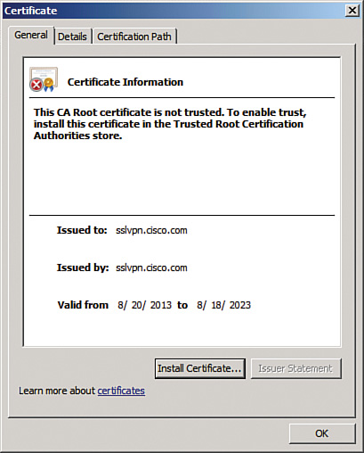
2. Verify whether the SSL VPN service home page displays both SSL groups, as shown in Figure 2a-14.

3. Verify that group selection and entry of usernames and passwords provide the correct access for the clientless group.
Group: SSL
Username: user1
Result: Redirect to the R3 home page
The login prompt to access the HTTP server of R3 should appear, as shown in Figure 2a-15.
On ASA2, this SSL session will appear as Clientless:
ASA2# show vpn-sessiondb
---------------------------------------------------------------------------
VPN Session Summary
---------------------------------------------------------------------------
Active : Cumulative : Peak Concur : Inactive
----------------------------------------------
AnyConnect Client : 0 : 1 : 1 : 0
SSL/TLS/DTLS : 0 : 1 : 1 : 0
Clientless VPN : 2 : 2 : 2
Browser : 2 : 2 : 2
---------------------------------------------------------------------------
Total Active and Inactive : 2 Total Cumulative : 3
Device Total VPN Capacity : 750
Device Load : 0%
---------------------------------------------------------------------------
---------------------------------------------------------------------------
Tunnels Summary
---------------------------------------------------------------------------
Active : Cumulative : Peak Concurrent
----------------------------------------------
Clientless : 2 : 3 : 2
SSL-Tunnel : 0 : 1 : 1
DTLS-Tunnel : 0 : 1 : 1
---------------------------------------------------------------------------
Totals : 2 : 5
---------------------------------------------------------------------------
To verify the correct group was selected for this connection, use the following output. Note that this session should clear after 1 minute of inactivity, although the inactivity timer in the output is not incrementing.
ASA2# sho vpn-sessiondb webvpn
Session Type: WebVPN
Username : user1 Index : 17
Public IP : 192.168.2.25
Protocol : Clientless
License : AnyConnect Premium
Encryption : RC4 Hashing : SHA1
Bytes Tx : 2401236 Bytes Rx : 233208
Group Policy : SSL Tunnel Group : SSL
Login Time : 16:29:31 UTC Fri Oct 4 2013
Duration : 0h:04m:43s
Inactivity : 0h:00m:00s
NAC Result : Unknown
VLAN Mapping : N/A VLAN : none
ASA2# show runn | begin group-policy SSL attributes
group-policy SSL attributes
vpn-idle-timeout 1
vpn-tunnel-protocol ssl-clientless
webvpn
homepage value http://r3.cisco.com
4. Verify that group selection and entry of usernames and passwords provide the correct access for the anyconnect group
Group: anySSL
Username: user2
Result: Use identity firewall to permit access to 10.50.40.0/24 only from 192.168.100.0/24. This subnet contains addresses assigned via IP address pool anyssl-clients.
ASA2# show vpn-sessiondb anyconnect
Session Type: AnyConnect
Username : user2 Index : 19
Assigned IP : 192.168.100.100 Public IP : 192.168.2.25
Protocol : Clientless SSL-Tunnel DTLS-Tunnel
License : AnyConnect Premium
Encryption : RC4 RC4 AES128 Hashing : SHA1 SHA1 SHA1
Bytes Tx : 58736 Bytes Rx : 38825
Group Policy : anySSL Tunnel Group : anySSL
Login Time : 19:20:04 UTC Fri Oct 4 2013
Duration : 0h:06m:34s
Inactivity : 0h:00m:00s
NAC Result : Unknown
VLAN Mapping : N/A VLAN : none
When user2 has been authenticated, the identity FW access list (vpn-filter) should be enforced by associating this vpn-filter with user2 as follows:
username user2 attributes
vpn-filter value user2
Any activity sourced from an address pool assigned IP destined to 10.50.40.0/24 will pass through the SSL VPN tunnel.
The vpn-filter command requires that return flows be explicitly defined; otherwise, traffic will not be sent back through the SSL tunnel to the client due to implicit deny conditions. Note that the LOCAL domain will ensure that user credentials are referenced locally on the ASA:
ASA2# show access-list
access-list user2 line 1 extended permit ip user LOCALuser2 192.168.100.0
255.255.255.0 10.50.40.0 255.255.255.0 (hitcnt=6) 0x91a6b0d4
access-list user2 line 2 extended permit ip any 10.50.40.0 255.255.255.0
(hitcnt=1) 0x4bb1a95b
Routes to the SSL client hosts are automatically created based on the assigned IP address:
ASA2# show route
S 192.168.100.100 255.255.255.255 [1/0] via 10.50.50.5, outside
Note
AnyConnect assigns the first address in a subnet mapping to an address pool to the default gateway. In this case, 192.168.100.1/24 is automatically assumed to be the default gateway for the SSL client on the Test-PC. To ensure there will be actual connectivity for this assignment, VLAN192 was created on SW1 using 192.168.100.1/24. A static route should be added to ASA/c1 and R6 to advertise this new subnet. R6 will propagate the route into the OSPF AS:
ASA1/c1# show route
Codes: C - connected, S - static, I - IGRP, R - RIP, M - mobile, B - BGP
D - EIGRP, EX - EIGRP external, O - OSPF, IA - OSPF inter area
N1 - OSPF NSSA external type 1, N2 - OSPF NSSA external type 2
E1 - OSPF external type 1, E2 - OSPF external type 2, E - EGP
i - IS-IS, L1 - IS-IS level-1, L2 - IS-IS level-2, ia - IS-IS inter area
* - candidate default, U - per-user static route, o - ODR
P - periodic downloaded static route
Gateway of last resort is 10.50.80.6 to network 0.0.0.0
C 10.50.80.0 255.255.255.0 is directly connected, outside
C 192.168.2.0 255.255.255.0 is directly connected, inside
S 192.168.100.0 255.255.255.0 [1/0] via 192.168.2.5, inside
S* 0.0.0.0 0.0.0.0 [1/0] via 10.50.80.6, outside