
Configuration
access-list user2 extended permit ip user LOCALuser2 any 10.50.40.0 255.255.255.0
access-list user2 extended permit ip any 10.50.0.0 255.255.0.0
ip local pool anyssl-clients 192.168.100.100-192.168.100.200
user-identity default-domain LOCAL
crypto ca trustpoint localtrust
enrollment self
fqdn sslvpn.cisco.com
subject-name CN=sslvpn.cisco.com
keypair sslvpnkeypair
crl configure
crypto ca certificate chain localtrust
certificate 8b7ef551
308201ef 30820158 a0030201 0202048b 7ef55130 0d06092a 864886f7 0d010105...
ssl trust-point localtrust outside
webvpn
enable outside
anyconnect image disk0:/anyconnect-win-3.0.11042-k9.pkg 1
anyconnect enable
tunnel-group-list enable
group-policy SSL internal
group-policy SSL attributes
vpn-idle-timeout 1
webvpn
homepage value http://r3.cisco.com
vpn-tunnel-protocol ssl-clientless
group-policy anySSL internal
group-policy anySSL attributes
dns-server value 192.168.2.25
vpn-tunnel-protocol ssl-client
default-domain value cisco.com
address-pools value anyssl-clients
username user1 password mbO2jYs13AXlIAGa encrypted
username user2 password mbO2jYs13AXlIAGa encrypted
username user2 attributes
vpn-filter value user2
service-type remote-access
tunnel-group anySSL type remote-access
tunnel-group anySSL general-attributes
default-group-policy anySSL
tunnel-group anySSL webvpn-attributes
group-alias AnySSL enable
tunnel-group SSL type remote-access
tunnel-group SSL general-attributes
default-group-policy SSL
tunnel-group SSL webvpn-attributes
group-alias SSL enable
Tech Notes
Importing Third-Party Trusted CA Certificates
This exercise covered the use of a self-signed certificate, but in reality, certificates authenticated and issued by trusted certificate authority servers will be used. The following is an example of using the VeriSign certificate service with the Cisco ASA using a manual enrollment method. This procedure can be followed for other certificate services when using the ASA CLI. The Cisco ASA will support multiple CA servers and identities through the use of unique trustpoints. This example uses a manual method because not all CA services support the Cisco Simple Certificate Enrollment Protocol (SCEP). Additionally, trusted CA servers that support thousands of end entity credentials are governed by very strict security policies that often mandate these servers not be accessible by the outside world.
1. Create the key pair to be used for the specific role and trustpoint on the ASA, and generate the PKCS #10 end entity certificate request to be sent (generally via email) to the CA server administrator:
ciscoasa# conf t
ciscoasa(config)# crypto key generate rsa label my.verisign.key modulus 1024
! Generates 1024 bit RSA key pair. "label" defines
! the name of the Key Pair.
INFO: The name for the keys will be: my.verisign.key
Keypair generation process begin. Please wait...
ciscoasa(config)# crypto ca trustpoint my.verisign.trustpoint
ciscoasa(config-ca-trustpoint)# subject-name CN=webvpn.cisco.com,OU=TSWEB,
O=Cisco Systems,C=US,St=North Carolina,L=Raleigh
ciscoasa(config-ca-trustpoint)# keypair my.verisign.key
ciscoasa(config-ca-trustpoint)# fqdn webvpn.cisco.com
ciscoasa(config-ca-trustpoint)# enrollment terminal
ciscoasa(config-ca-trustpoint)# exit
ciscoasa(config)# crypto ca enroll my.verisign.trustpoint
% Start certificate enrollment ..
% The subject name in the certificate will be: CN=webvpn.cisco.com,OU=TSWEB,
O=Cisco Systems,C=US,St=North Carolina,L=Raleigh
% The fully-qualified domain name in the certificate will be:
webvpn.cisco.com
% Include the device serial number in the subject name? [yes/no]: no
Display Certificate Request to terminal? [yes/no]: yes
! Displays the PKCS#10 enrollment request to the terminal.
! You will need to copy this from the terminal to a text
! file or web text field to submit to the 3rd party CA.
Certificate Request follows:
MIICHjCCAYcCAQAwgaAxEDAOBgNVBAcTB1JhbGVpZ2gxFzAVBgNVBAgTDk5vcnRo
IENhcm9saW5hMQswCQYDVQQGEwJVUzEWMBQGA1UEChMNQ2lzY28gU3lzdGVtczEO
MAwGA1UECxMFVFNXRUIxGzAZBgNVBAMTEmNpc2NvYXNhLmNpc2NvLmNvbTEhMB8G
CSqGSIb3DQEJAhYSY2lzY29hc2EuY2lzY28uY29tMIGfMA0GCSqGSIb3DQEBAQUA
A4GNADCBiQKBgQCmM/2VteHnhihS1uOj0+hWa5KmOPpI6Y/MMWmqgBaB9M4yTx5b
Fm886s8F73WsfQPynBDfBSsejDOnBpFYzKsGf7TUMQB2m2RFaqfyNxYt3oMXSNPO
m1dZ0xJVnRIp9cyQp/983pm5PfDD6/ho0nTktx0i+1cEX0luBMh7oKargwIDAQAB
oD0wOwYJKoZIhvcNAQkOMS4wLDALBgNVHQ8EBAMCBaAwHQYDVR0RBBYwFIISY2lz
Y29hc2EuY2lzY28uY29tMA0GCSqGSIb3DQEBBAUAA4GBABrxpY0q7SeOHZf3yEJq
po6wG+oZpsvpYI/HemKUlaRc783w4BMO5lulIEnHgRqAxrTbQn0B7JPIbkc2ykkm
bYvRt/wiKc8FjpvPpfOkjMK0T3t+HeQ/5QlKx2Y/vrqs+Hg5SLHpbhj/Uo13yWCe
0Bzg59cYXq/vkoqZV/tBuACr
---End - This line not part of the certificate request---
2. Request and verify the CA server’s base 64–encoded certificate. This certificate can be cut and pasted using the ASA CLI. Note that a write memory is required to save this certificate for later use.
ciscoasa(config)# crypto ca authenticate my.verisign.trustpoint
Enter the base 64 encoded CA certificate.
End with the word "quit" on a line by itself
-----BEGIN CERTIFICATE-----
MIIEwDCCBCmgAwIBAgIQY7GlzcWfeIAdoGNs+XVGezANBgkqhkiG9w0BAQUFADCB
jDELMAkGA1UEBhMCVVMxFzAVBgNVBAoTDlZlcmlTaWduLCBJbmMuMTAwLgYDVQQL
EydGb3IgVGVzdCBQdXJwb3NlcyBPbmx5LiAgTm8gYXNzdXJhbmNlcy4xMjAwBgNV
BAMTKVZlcmlTaWduIFRyaWFsIFNlY3VyZSBTZXJ2ZXIgVGVzdCBSb290IENBMB4X
DTA1MDIwOTAwMDAwMFoXDTE1MDIwODIzNTk1OVowgcsxCzAJBgNVBAYTAlVTMRcw
FQYDVQQKEw5WZXJpU2lnbiwgSW5jLjEwMC4GA1UECxMnRm9yIFRlc3QgUHVycG9z
ZXMgT25seS4gIE5vIGFzc3VyYW5jZXMuMUIwQAYDVQQLEzlUZXJtcyBvZiB1c2Ug
YXQgaHR0cHM6Ly93d3cudmVyaXNpZ24uY29tL2Nwcy90ZXN0Y2EgKGMpMDUxLTAr
BgNVBAMTJFZlcmlTaWduIFRyaWFsIFNlY3VyZSBTZXJ2ZXIgVGVzdCBDQTCCASIw
DQYJKoZIhvcNAQEBBQADggEPADCCAQoCggEBALsXGt1M4HyjXwA+/NAuwElv6IJ/
DV8zgpvxuwdaMv6fNQBHSF4eKkFDcJLJVnP53ZiGcLAAwTC5ivGpGqE61BBD6Zqk
d85lPl/6XxK0EdmrN7qVMmvBMGRsmOjje1op5f0nKPqVoNK2qNUB6n451P4qoyqS
E0bdru16quZ+II2cGFAG1oSyRy4wvY/dpVHuZOZqYcIkK08yGotR2xA1D/OCCmZO
5RmNqLLKSVwYHhJ25EskFhgR2qCxX2EQJdnDXuTw0+4tlqj97ydk5iDoxjKfV6sb
tnp3TIY6S07bTb9gxJCk4pGbcf8DOPvOfGRu1wpfUUZC8v+WKC20+sK6QMECAwEA
AaOCAVwwggFYMBIGA1UdEwEB/wQIMAYBAf8CAQAwSwYDVR0gBEQwQjBABgpghkgB
hvhFAQcVMDIwMAYIKwYBBQUHAgEWJGh0dHBzOi8vd3d3LnZlcmlzaWduLmNvbS9j
cHMvdGVzdGNhLzAOBgNVHQ8BAf8EBAMCAQYwEQYJYIZIAYb4QgEBBAQDAgEGMB0G
A1UdDgQWBBRmIo6B4DFZ3Sp/q0bFNgIGcCeHWjCBsgYDVR0jBIGqMIGnoYGSpIGP
MIGMMQswCQYDVQQGEwJVUzEXMBUGA1UEChMOVmVyaVNpZ24sIEluYy4xMDAuBgNV
BAsTJ0ZvciBUZXN0IFB1cnBvc2VzIE9ubHkuICBObyBhc3N1cmFuY2VzLjEyMDAG
A1UEAxMpVmVyaVNpZ24gVHJpYWwgU2VjdXJlIFNlcnZlciBUZXN0IFJvb3QgQ0GC
ECCol67bggLewTagTia9h3MwDQYJKoZIhvcNAQEFBQADgYEASz5v8s3/SjzRvY2l
Kqf234YROiL51ZS111oUZ2MANp2H4biw4itfsG5snDDlwSRmiH3BW/SU6EEzD9oi
Ai9TXvRIcD5q0mB+nyK9fB2aBzOiaiHSiIWzAJeQjuqA+Q93jNew+peuj4AhdvGN
n/KK/+1Yv61w3+7g6ukFMARVBNg=
-----END CERTIFICATE-----
quit
After manually pasting the certificate into CLI, verify the certificate fingerprint display with the fingerprint, which should be supplied by the CA authority via an out-of-band mechanism.
INFO: Certificate has the following attributes:
Fingerprint: 8de989db 7fcc5e3b fdde2c42 0813ef43
Do you accept this certificate? [yes/no]: yes
Trustpoint 'my.verisign.trustpoint' is a subordinate CA and
holds a non self-signed certificate.
Trustpoint CA certificate accepted.
% Certificate successfully imported
ciscoasa(config)#
ciscoasa(config-ca-trustpoint)# exit
3. After the end entity certificate for the Cisco ASA has been received, it must be imported and saved. This is done from the ASA CLI as follows.
ciscoasa(config)# crypto ca import my.verisign.trustpoint certificate
! Initiates prompt to paste the base64 identity
! certificate provided by the 3rd party vendor.
% The fully-qualified domain name in the certificate will be: webvpn.cisco.com
Enter the base 64 encoded certificate.
End with the word "quit" on a line by itself
-----BEGIN CERTIFICATE-----
MIIFZjCCBE6gAwIBAgIQMs/oXuu9K14eMGSf0mYjfTANBgkqhkiG9w0BAQUFADCB
yzELMAkGA1UEBhMCVVMxFzAVBgNVBAoTDlZlcmlTaWduLCBJbmMuMTAwLgYDVQQL
EydGb3IgVGVzdCBQdXJwb3NlcyBPbmx5LiAgTm8gYXNzdXJhbmNlcy4xQjBABgNV
BAsTOVRlcm1zIG9mIHVzZSBhdCBodHRwczovL3d3dy52ZXJpc2lnbi5jb20vY3Bz
L3Rlc3RjYSAoYykwNTEtMCsGA1UEAxMkVmVyaVNpZ24gVHJpYWwgU2VjdXJlIFNl
cnZlciBUZXN0IENBMB4XDTA3MDcyNjAwMDAwMFoXDTA3MDgwOTIzNTk1OVowgbox
CzAJBgNVBAYTAlVTMRcwFQYDVQQIEw5Ob3J0aCBDYXJvbGluYTEQMA4GA1UEBxQH
UmFsZWlnaDEWMBQGA1UEChQNQ2lzY28gU3lzdGVtczEOMAwGA1UECxQFVFNXRUIx
OjA4BgNVBAsUMVRlcm1zIG9mIHVzZSBhdCB3d3cudmVyaXNpZ24uY29tL2Nwcy90
ZXN0Y2EgKGMpMDUxHDAaBgNVBAMUE2Npc2NvYXNhMS5jaXNjby5jb20wgZ8wDQYJ
KoZIhvcNAQEBBQADgY0AMIGJAoGBAL56EvorHHlsIB/VRKaRlJeJKCrQ/9kER2JQ
9UOkUP3mVPZJtYN63ZxDwACeyNb+liIdKUegJWHI0Mz3GHqcgEkKW1EcrO+6aY1R
IaUE8/LiAZbA70+k/9Z/UR+v532B1nDRwbx1R9ZVhAJzA1hJTxSlEgryosBMMazg
5IcLhgSpAgMBAAGjggHXMIIB0zAJBgNVHRMEAjAAMAsGA1UdDwQEAwIFoDBDBgNV
HR8EPDA6MDigNqA0hjJodHRwOi8vU1ZSU2VjdXJlLWNybC52ZXJpc2lnbi5jb20v
U1ZSVHJpYWwyMDA1LmNybDBKBgNVHSAEQzBBMD8GCmCGSAGG+EUBBxUwMTAvBggr
BgEFBQcCARYjaHR0cHM6Ly93d3cudmVyaXNpZ24uY29tL2Nwcy90ZXN0Y2EwHQYD
VR0lBBYwFAYIKwYBBQUHAwEGCCsGAQUFBwMCMB8GA1UdIwQYMBaAFGYijoHgMVnd
Kn+rRsU2AgZwJ4daMHgGCCsGAQUFBwEBBGwwajAkBggrBgEFBQcwAYYYaHR0cDov
L29jc3AudmVyaXNpZ24uY29tMEIGCCsGAQUFBzAChjZodHRwOi8vU1ZSU2VjdXJl
LWFpYS52ZXJpc2lnbi5jb20vU1ZSVHJpYWwyMDA1LWFpYS5jZXIwbgYIKwYBBQUH
AQwEYjBgoV6gXDBaMFgwVhYJaW1hZ2UvZ2lmMCEwHzAHBgUrDgMCGgQUS2u5KJYG
DLvQUjibKaxLB4shBRgwJhYkaHR0cDovL2xvZ28udmVyaXNpZ24uY29tL3ZzbG9n
bzEuZ2lmMA0GCSqGSIb3DQEBBQUAA4IBAQAnym4GVThPIyL/9ylDBd8N7/yW3Ov3
bIirHfHJyfPJ1znZQXyXdObpZkuA6Jyu03V2CYNnDomn4xRXQTUDD8q86ZiKyMIj
XM2VCmcHSajmMMRyjpydxfk6CIdDMtMGotCavRHD9Tl2tvwgrBock/v/54o02lkB
SmLzVV7crlYJEuhgqu3Pz7qNRd8N0Un6c9sbwQ1BuM99QxzIzdAo89FSewy8MAIY
rtab5F+oiTc5xGy8w7NARAfNgFXihqnLgWTtA35/oWuy86bje1IWbeyqj8ePM9Td
0LdAw6kUU1PNimPttMDhcF7cuevntROksOgQPBPx5FJSqMiUZGrvju5O
-----END CERTIFICATE-----
quit
INFO: Certificate successfully imported
ciscoasa(config)#
ciscoasa(config)# show crypto ca certificates
! Display the certificates installed on the ASA.
Certificate
Status: Available
Certificate Serial Number: 32cfe85eebbd2b5e1e30649fd266237d
Certificate Usage: General Purpose
Public Key Type: RSA (1024 bits)
Issuer Name:
cn=VeriSign Trial Secure Server Test CA
ou=Terms of use at https://www.verisign.com/cps/testca ©)05
ou=For Test Purposes Only. No assurances.
o=VeriSign, Inc.
c=US
Subject Name:
cn=webvpn.cisco.com
ou=Terms of use at www.verisign.com/cps/testca ©)05
ou=TSWEB
o=Cisco Systems
l=Raleigh
st=North Carolina
c=US
OCSP AIA:
URL: http://ocsp.verisign.com
CRL Distribution Points:
[1] http://SVRSecure-crl.verisign.com/SVRTrial2005.crl
Validity Date:
start date: 00:00:00 UTC Jul 19 2007
end date: 23:59:59 UTC Aug 2 2007
Associated Trustpoints: my.verisign.trustpoint
CA Certificate
Status: Available
Certificate Serial Number: 63b1a5cdc59f78801da0636cf975467b
Certificate Usage: General Purpose
Public Key Type: RSA (2048 bits)
Issuer Name:
cn=VeriSign Trial Secure Server Test Root CA
ou=For Test Purposes Only. No assurances.
o=VeriSign, Inc.
c=US
Subject Name:
cn=VeriSign Trial Secure Server Test CA
ou=Terms of use at https://www.verisign.com/cps/testca ©)05
ou=For Test Purposes Only. No assurances.
o=VeriSign, Inc.
c=US
Validity Date:
start date: 00:00:00 UTC Feb 9 2005
end date: 23:59:59 UTC Feb 8 2015
Associated Trustpoints: my.verisign.trustpoint
Default Group Policy and Attribute Inheritance
The ASA is configured with a default group policy. You can modify this default group policy, but you cannot delete it. The default group policy, named DfltGrpPolicy, always exists on the ASA but does not take effect unless the ASA is configured to use it. When you configure other named group policies, any attribute not explicitly specified takes its value from the default group policy. To view the default group policy, enter the following command:
hostname# show run all group-policy DfltGrpPolicy
Solution and Verification for Exercise 3.4: Configure and Troubleshoot FlexVPN Site-to-Site Using RADIUS Tunnel Attributes
Skills Tested
![]() Configuring IKEv2 on a Cisco IOS Router
Configuring IKEv2 on a Cisco IOS Router
![]() Understanding the concepts of FlexVPN in a dynamic site-to-site model using dynamic routing
Understanding the concepts of FlexVPN in a dynamic site-to-site model using dynamic routing
![]() Implementing AAA integration for IKEv2 using RADIUS to the CiscoSecure ACS authentication server
Implementing AAA integration for IKEv2 using RADIUS to the CiscoSecure ACS authentication server
Solution and Verification
FlexVPN is an umbrella term used to describe VPN solutions that use IKEv2 for tunnel negotiation and control and IPsec-protected virtual interfaces for data transport.
IKEv2 is the IETF standards-based successor to IKEv1. It was originally defined in RFC 4306, which has most recently been replaced by RFC 5996. The reader should be familiar with the implementation of both versions of IKE and the key differences from a protocol perspective. Table 2a-4 summarizes the major changes.

To complete this solution, the IKEv2 policy, profiles, and other constructs such as the name-mangler must be completed using the partial configurations defined on R7 and R6 as well as the outputs provided in the question itself. The IKEv2 implementation in Cisco IOS provides support for IKEv2 smart defaults. In this exercise, user-defined policies overrule these default parameters. The IKEv2 name-mangler is a function that takes the value of the IKE ID type passed by the remote peer to create a “username” that will index the AAA database for authorization requests. This exercise uses the FQDN value sent by R7; however, any portion of the IKE ID, based on any ID type, can be referenced when using this command. RADIUS AAA authorization for service “network” will use the IKEv2 name-mangler created username (R7.cisco.com) and the default password cisco. All Cisco IOS authorization requests use service=outbound send password cisco.
RIPv2 is being used for dynamic routing across the FlexVPN and will act as the tunnel initiation mechanism.
The configuration section that follows highlights the commands required to complete the configuration. When a virtual-template interface is used on R6, it implies that R6 will not initiate the FlexVPN.
For all verification syntax that follows:
![]() Required output appears in red
Required output appears in red
![]() Required tasks appear in indigo
Required tasks appear in indigo
Verify whether R6 (via a virtual-access interface) and R7 (via interface Tunnel1) should be reporting ACTIVE SAs:
R7# show crypto session
Crypto session current status
Interface: Tunnel1
Session status: UP-ACTIVE
Peer: 10.50.70.6 port 500
IKEv2 SA: local 10.50.40.7/500 remote 10.50.70.6/500 Active
IPSEC FLOW: permit ip 0.0.0.0/0.0.0.0 0.0.0.0/0.0.0.0
Active SAs: 2, origin: crypto map
R6# show crypto session
Crypto session current status
Interface: Virtual-Access1
Session status: UP-ACTIVE
Peer: 10.50.40.7 port 500
IKEv2 SA: local 10.50.70.6/500 remote 10.50.40.7/500 Active
IPSEC FLOW: permit ip 0.0.0.0/0.0.0.0 0.0.0.0/0.0.0.0
Active SAs: 2, origin: crypto map
The show crypto ikev2 session detailed command displays the IKEv2 and IPsec (child) SA policies negotiated between R6 and R7. This verifies whether the user-defined policy and profile configuration was correctly completed:
R6# show crypto ikev2 session detailed
IPv4 Crypto IKEv2 Session
Session-id:18, Status:UP-ACTIVE, IKE count:1, CHILD count:1
Tunnel-id Local Remote fvrf/ivrf Status
1 10.50.70.6/500 10.50.40.7/500 none/none READY
Encr: AES-CBC, keysize: 256, Hash: SHA256, DH Grp:5, Auth sign: PSK, Auth
verify: PSK
Life/Active Time: 86400/1014 sec
CE id: 1008, Session-id: 18
Status Description: Negotiation done
Local spi: D60B62C207327A3D Remote spi: 609E382CB11281D3
Local id: r6.cisco.com
Remote id: r7.cisco.com
Local req msg id: 0 Remote req msg id: 2
Local next msg id: 0 Remote next msg id: 2
Local req queued: 0 Remote req queued: 2
Local window: 5 Remote window: 5
DPD configured for 0 seconds, retry 0
NAT-T is not detected
Cisco Trust Security SGT is disabled
Child sa: local selector 0.0.0.0/0 - 255.255.255.255/65535
remote selector 0.0.0.0/0 - 255.255.255.255/65535
ESP spi in/out: 0x88B600C5/0xDE40CB3B
AH spi in/out: 0x0/0x0
CPI in/out: 0x0/0x0
Encr: AES-CBC, keysize: 128, esp_hmac: SHA96
ah_hmac: None, comp: IPCOMP_NONE, mode tunnel
The predefined RIP-2 configuration should be correctly propagating routing information between R6 and R7:
R7# show ip route
R 172.17.60.0/24 [120/1] via 172.16.70.6, 00:00:07, Tunnel1
R6# show ip route
R 172.17.70.0/24 [120/1] via 172.16.70.7, 00:00:21, Virtual-Access1
Verify whether AAA was correctly referenced and configured with respect to the CiscoSecure ACS server by checking the RADIUS authentication logs on 192.168.2.18, as shown in Figure 2a-16.

R6
aaa new-model
!
!
aaa authorization network list1 group radius
!
crypto ikev2 proposal 1
encryption aes-cbc-256
integrity sha256
group 5
!
crypto ikev2 policy lan2lan
match fvrf any
proposal 1
crypto ikev2 name-mangler identities
fqdn all
!
crypto ikev2 profile flexvpn
match identity remote fqdn domain cisco.com
identity local fqdn r6.cisco.com
authentication local pre-share
authentication remote pre-share
keyring aaa list1 name-mangler identities
virtual-template 1
!
crypto ipsec profile flexvpn
set ikev2-profile flexvpn
!
interface Loopback3
ip address 172.16.70.6 255.255.255.0
!
interface Ethernet0/1
ip address 10.50.70.6 255.255.255.0
interface Virtual-Template1 type tunnel
ip unnumbered Loopback3
tunnel source Ethernet0/1
tunnel mode ipsec ipv4
tunnel protection ipsec profile flexvpn
!
radius-server host 192.168.2.18 key cisco
!
router rip
version 2
passive-interface Ethernet0/0
network 172.16.0.0
network 172.17.0.0
no auto-summary
R7
crypto ikev2 proposal 1
encryption aes-cbc-256
integrity sha256
group 5
!
crypto ikev2 policy lan2lan
match fvrf any
proposal 1
!
!
crypto ikev2 keyring flexvpn
peer r6
identity fqdn r6.cisco.com
pre-shared-key cisco
!
!
!
crypto ikev2 profile flexvpn
match identity remote fqdn r6.cisco.com
identity local fqdn r7.cisco.com
authentication local pre-share
authentication remote pre-share
keyring local flexvpn
!
crypto ipsec profile flexvpn
set ikev2-profile flexvpn
interface Tunnel1
ip address 172.16.70.7 255.255.255.0
tunnel source GigabitEthernet0/1
tunnel mode ipsec ipv4
tunnel destination 10.50.70.6
tunnel protection ipsec profile flexvpn
router rip
version 2
network 172.16.0.0
network 172.17.0.0
no auto-summary
Tech Notes
IKEv2 Smart Defaults
The Cisco IOS IKEv2 implementation includes policy and proposal smart defaults that eliminate the necessity for the user to add lines of configuration to facilitate various combinations of attributes that might be negotiated between peers. The benefit is reduced configuration and policy management overhead. One of the disadvantages of using smart defaults is that uniform policy enforcement might not occur as expected if one peer (without smart defaults) is misconfigured and negotiates a lower level of security. If both peers support smart defaults, the first policy match will be applied, which again might not be optimal. The other issue is in terms of performance and number of proposals sent by the initiator. Like an EZVPN client, which sends all combinations of proposal elements (auth method, encryption algorithm, and so on), the smart default–based initiator will send all combinations of proposals defined in the default protection suite with the expectation that the peer will accept one, even if it is the last combination!
The default IKEv2 policy and proposal suites can be displayed using the following commands:
show crypto ikev2 policy default
IKEv2 policy : default
Match fvrf : any
Match address local : any
Proposal : default
show crypto ikev2 proposal default
IKEv2 proposal: default
Encryption : AES-CBC-256 AES-CBC-192 AES-CBC-128
Integrity : SHA512 SHA384 SHA256 SHA96 MD596
PRF : SHA512 SHA384 SHA256 SHA1 MD5
DH Group : DH_GROUP_1536_MODP/Group 5 DH_GROUP_1024_MODP/Group 2
IKEv2 Anti-Clogging Cookie
In IKEv2, cookies serve two purposes. First, they are used as IKE SA identifiers in the headers of IKE messages. As with ESP and AH, in IKEv2 the recipient of a message chooses an IKE SA identifier that uniquely defines that SA to that recipient. The IKE SA identifier is then used as part of a security association database (SADB) index.
Cookies in IKEv2 have a second function. To reduce the potential of IKE protocol-based DoS attacks, the IKEv2 anti-clogging cookie feature is available in Cisco IOS. Receipt of a request to start an SA can consume substantial resources. A likely denial-of-service attack using the IKE protocol is to overwhelm a system with large numbers of SA requests from forged IP addresses. Upon receipt of an IKE_SA_init, a responder can either proceed with setting up the SA or can tell the initiator to send another IKE_SA_init, this time providing a supplied cookie. If the initiator was not a legitimate sender of an initiation message, it will not respond to the cookie exchange and the responder will not proceed with the original IKE request.
To prevent adding the overhead of this extra IKE exchange for each SA request, the anti-clogging cookie is a user-configurable option that enables an IKEv2 cookie challenge for incoming requests only when the number of half-open SAs exceeds a configured number. The command syntax is as follows:
crypto ikev2 cookie-challenge number of half-opened SAs
RADIUS Tunnel Attributes and IKEv2
As with IKEv1, RADIUS may be used to retrieve a preshared key and other authorization attributes from an AAA server for IKEv2. The following debug snapshot shows AAA integration with IKEv2.
R6 receives the IKE_AUTH(i) message from R7 and will use the IKE ID type and its value to build a username R7.cisco.com with default password cisco, to be used as the RADIUS user credentials to fetch the preshared key for R7.
IKEv2:(SA ID = 1):Stopping timer to wait for auth message
IKEv2:(SA ID = 1):Checking NAT discovery
IKEv2:(SA ID = 1):NAT not found
IKEv2:(SA ID = 1):Searching policy based on peer's identity 'r7.cisco.com' of
type 'FQDN'
IKEv2:found matching IKEv2 profile 'flexvpn'
IKEv2:Searching Policy with fvrf 0, local address 10.50.70.6
IKEv2:Found Policy 'lan2lan'
IKEv2:(SA ID = 1):Verify peer's policy
IKEv2:(SA ID = 1):Peer's policy verified
IKEv2:(SA ID = 1):Get peer's authentication method
IKEv2:(SA ID = 1):Peer's authentication method is 'PSK'
IKEv2:(SA ID = 1):Get peer's preshared key for r7.cisco.com
IKEv2:(SA ID = 1):[IKEv2 -> AAA] Password request sent
RADIUS/ENCODE(00000045):Orig. component type = VPN IPSEC
RADIUS(00000045): Config NAS IP: 0.0.0.0
RADIUS(00000045): Config NAS IPv6: ::
RADIUS/ENCODE(00000045): acct_session_id: 58
RADIUS(00000045): sending
RADIUS/ENCODE: Best Local IP-Address 10.50.80.6 for Radius-Server 192.168.2.18
RADIUS(00000045): Send Access-Request to 192.168.2.18:1645 id 1645/2, len 76
RADIUS: authenticator 7E 27 B9 E8 5E 69 3C 5F - 40 16 FD 66 AF DE ED 10
RADIUS: User-Name [1] 14 "r7.cisco.com"
RADIUS: User-Password [2] 18 *
R6#
RADIUS: Calling-Station-Id [31] 12 "10.50.40.7"
RADIUS: Service-Type [6] 6 Outbound [5]
RADIUS: NAS-IP-Address [4] 6 10.50.80.6
RADIUS(00000045): Sending a IPv4 Radius Packet
RADIUS(00000045): Started 5 sec timeout
RADIUS: Received from id 1645/2 192.168.2.18:1645, Access-Accept, len 184
RADIUS: authenticator C4 1C B7 E9 52 87 19 3E - 3C 66 05 77 D7 1D 25 C3
RADIUS: User-Name [1] 14 "r7.cisco.com"
RADIUS: Class [25] 22
RADIUS: 43 41 43 53 3A 61 63 73 2F 31 36 34 31 35 34 37 [CACS:acs/1641547]
RADIUS: 31 35 2F 32 [ 15/2]
RADIUS: Tunnel-Type [64] 6 01:ESP [9]
RADIUS: Tunnel-Medium-Type [65] 6 01:IPv4 [1]
RADIUS: Vendor, Cisco [26] 35
RADIUS: Cisco AVpair [1] 29 "ipsec:tunnel-password=cisco"
RADIUS: Vendor, Cisco [26] 40
RADIUS: Cisco AVpair [1] 34 "ipsec:ikev2-password-local=cisco"
RADIUS: Vendor, Cisco [26] 41
RADIUS: Cisco AVpair [1] 35 "ipsec:ikev2-password-remote=cisco"
RADIUS(00000045): Received from id 1645/2
IKEv2:(SA ID = 1):[AAA -> IKEv2] Received password response
IKEv2:unsupported attr type 445
IKEv2:unsupported attr type 437
IKEv2:unsupported attr type 438
IKEv2:unsupported attr type 473
IKEv2:unsupported attr type 474
IKEv2:(SA ID = 1):Verify peer's authentication data
IKEv2:(SA ID = 1):Use preshared key for id r7.cisco.com, key len 5
IKEv2:[IKEv2 -> Crypto Engine] Generate IKEv2 authentication data
IKEv2:[Crypto Engine -> IKEv2] IKEv2 authentication data generation PASSED
IKEv2:(SA ID = 1):Verification of peer's authentication data PASSED
The RADIUS attributes seen in the preceding debug output are configured on the Cisco Secure ACS as shown in Figure 2a-17.

Solution and Verification for Exercise 3.5: Configure and Troubleshoot FlexVPN Remote Access (Client to Server)
Skills Tested
![]() Configuring IKEv2 with remote access client support on a Cisco IOS Router
Configuring IKEv2 with remote access client support on a Cisco IOS Router
![]() Understanding the concepts of FlexVPN in a client/server model
Understanding the concepts of FlexVPN in a client/server model
![]() Implementing IKEv2 integrated static route support
Implementing IKEv2 integrated static route support
Solution and Verification
This solution requires the FlexVPN client configuration on R4 to be completed and a VPN tunnel be successfully established with the FlexVPN server on R2. This client/server implementation of FlexVPN using IKEv2 is the alternative to the IKEv1-based EZVPN solution. IKEv2 for remote-access clients uses mode configuration and extended authentication (XAUTH) capabilities in the form of IKEv2 protocol integrated Configuration (CFG) payloads and support for Extensible Authentication Protocol (EAP). This differs from IKEv1, which added a Phase 1.5 between IKE (Phase 1) and IPsec (Phase 2) negotiation to support remote access VPN clients. Mode configuration and XAUTH were added to IKEv1 as extensions that were not supported by all vendors. In this question, preshared keys will be used for peer authentication. If EAP was required, it would be specified as the client authentication method and the server must then use rsa-signatures.
Server-defined attributes will be sent using IKEv2 config payloads and can be configured locally on the router or remotely on a AAA server accessible via RADIUS. This solution uses locally configured attributes using the crypto ikev2 authorization policy syntax that can also be used to incorporate other policy attributes, as defined in an aaa attribute list. This replaces the IKEv1-based crypto isakmp client configuration group syntax.
This solution also requires the use of new IKEv2 constructs to propagate address/mask information between peers that will be used to create static routes to control the forwarding of traffic requiring protection. The functionality of reverse route injection (RRI) is replaced by the route set and route accept commands.
Finally, in EZVPN with IKEv1, configuration mode functionality was explicitly configured in an ISAKMP profile. When defining an IKEv2 profile, configuration mode functionality is on by default via the following commands that are not displayed in the configuration:
![]() config-exchange set send
config-exchange set send
![]() config-exchange set accept
config-exchange set accept
![]() config-exchange request
config-exchange request
For all verification syntax that follows:
![]() Required output appears in red
Required output appears in red
![]() Required tasks appear in indigo
Required tasks appear in indigo
![]() Nonzero/nonnull syntax appears in violet
Nonzero/nonnull syntax appears in violet
![]() Variable syntax appears in green
Variable syntax appears in green
Verification of this solution requires the VPN tunnel to be established and ACTIVE. R4 must also receive all policy attributes from the server, which will be “pushed” in response to a client CONFIG-REQUEST.
Initiate the client connection from R4:
R4# crypto ikev2 client flexvpn connect
Check that the VPN connection state is ACTIVE using Tunnel0 as the logical interface and that an address has been assigned from the address pool defined on R2. Using ip address negotiated on T0 will ensure the assigned address is installed.
R4# show crypto ikev2 client flex
Profile : flex
Current state:ACTIVE
Peer : 10.50.100.2
Source : Ethernet0/1
ivrf : IP DEFAULT
fvrf : IP DEFAULT
Backup group: Default
Tunnel interface : Tunnel0
Assigned ip address: 172.17.100.55 <- should be between .50 and .60
Verify whether the IKEv2 proposals and IPsec transform set were correctly defined on R4. These negotiated algorithms are displayed in the show crypto ikev2 session detail command.
The protection suites were explicitly defined on R2 in lieu of using IKEv2 smart defaults. If both peers were configured to use smart defaults, the most secure supported (hardware dependent) protection suite match would be applied.
R4# show crypto ikev2 session detail
IPv4 Crypto IKEv2 Session
Session-id:2, Status:UP-ACTIVE, IKE count:1, CHILD count:1
Tunnel-id Local Remote fvrf/ivrf Status
1 10.50.30.4/500 10.50.100.2/500 none/none READY
Encr: AES-CBC, keysize: 256, Hash: SHA512, DH Grp:5, Auth sign: PSK, Auth
verify: PSK
Life/Active Time: 86400/277 sec
CE id: 1032, Session-id: 2
Status Description: Negotiation done
Local spi: 0696C6F582787B23 Remote spi: 49C2BF63CF74F456
Local id: R4.cisco.com
Remote id: 10.50.100.2
Local req msg id: 2 Remote req msg id: 0
Local next msg id: 2 Remote next msg id: 0
Local req queued: 2 Remote req queued: 0
Local window: 5 Remote window: 5
DPD configured for 0 seconds, retry 0
NAT-T is not detected
Cisco Trust Security SGT is disabled
Pushed IP address: 172.17.100.55
DNS Primary: 192.168.2.25
Child sa: local selector 0.0.0.0/0 - 255.255.255.255/65535
remote selector 0.0.0.0/0 - 255.255.255.255/65535
ESP spi in/out: 0xEEF6B847/0x81642A80
AH spi in/out: 0x0/0x0
CPI in/out: 0x0/0x0
Encr: 3DES, esp_hmac: MD596
ah_hmac: None, comp: IPCOMP_NONE, mode tunnel
The other key functionality to be verified is that routing information has been propagated between peers. If routes are not sent and accepted, data might not correctly be forwarded via the secure VPN.
The crypto ikev2 profile defined by the user must contain the following command syntax. Note that the use of flex as the AAA username will be a pointer to the locally configured authorization policy.
aaa authorization network list1 local
aaa authorization group psk list list1 flex
R4# show crypto ikev2 authorization policy
IKEv2 Authorization Policy : flex
route set interface
route set acl: routes <- this is a pointer to a pre-defined ACL that will form
the basis of a static route created on R2
route accept any tag : 1 distance : 1
Verify whether the route information was sent to R2 via a config-set. R2 will respond with a config-accept. Ping the Loopback0 interface of R4, and check IPsec counters to verify the VPN tunnel is being used to transport data.
R2# show ip route
S 172.17.100.55/32 is directly connected, Virtual-Access1
172.18.0.0/24 is subnetted, 1 subnets
S 172.18.34.0 is directly connected, Virtual-Access1
R2# ping 172.18.34.4
Type escape sequence to abort.
Sending 5, 100-byte ICMP Echos to 172.18.34.4, timeout is 2 seconds:
!!!!!
Success rate is 100 percent (5/5), round-trip min/avg/max = 5/5/6 ms
R2# show crypto ipsec sa
......
interface: Virtual-Access1
Crypto map tag: Virtual-Access1-head-0, local addr 10.50.100.2
protected vrf: (none)
local ident (addr/mask/prot/port): (0.0.0.0/0.0.0.0/0/0)
remote ident (addr/mask/prot/port): (0.0.0.0/0.0.0.0/0/0)
current_peer 10.50.30.4 port 500
PERMIT, flags={origin_is_acl,}
#pkts encaps: 5, #pkts encrypt: 5, #pkts digest: 5
#pkts decaps: 5, #pkts decrypt: 5, #pkts verify: 5
#pkts compressed: 0, #pkts decompressed: 0
#pkts not compressed: 0, #pkts compr. failed: 0
#pkts not decompressed: 0, #pkts decompress failed: 0
R4# show ip route
S 172.17.100.2/32 is directly connected, Tunnel0
C 172.17.100.55/32 is directly connected, Tunnel0
Configuration
Syntax highlighted in cyan needs to be added or modified.
R4
aaa authorization network list1 local
crypto ikev2 authorization policy flex
route set interface
route set access-list routes
crypto ikev2 keyring key
peer flexserver
address 0.0.0.0 0.0.0.0
pre-shared-key cisco
!
!
!
crypto ikev2 profile prof
match identity remote address 10.50.100.2 255.255.255.255
identity local fqdn R4.cisco.com
authentication local pre-share
authentication remote pre-share
keyring local key
aaa authorization group psk list list1 flex
config-exchange set send
config-exchange set accept
config-exchange request
!
crypto ikev2 client flexvpn flex
peer 1 10.50.100.2
connect manual
client connect Tunnel0
crypto ipsec profile ipsecprof
set transform-set 3des
set ikev2-profile prof
!
interface Loopback2
ip address 172.18.34.4 255.255.255.0
interface Tunnel0
ip address negotiated
tunnel source Ethernet0/1
tunnel mode ipsec ipv4
tunnel destination dynamic
tunnel protection ipsec profile ipsecprof
ip access-list standard routes
permit 172.18.34.0 0.0.0.255
R2
aaa authorization network local-list local
!
aaa attribute list ikev2ra
attribute type ipsec-backup-gateway "R1.cisco.com"
attribute type interface-config "ip mtu 1100"
!
!
!
crypto ikev2 name-mangler group-name
fqdn domain
!
!
crypto ikev2 authorization policy cisco.com
pool flex
dns 192.168.2.25
aaa attribute list ikev2ra
route set interface
route accept any
!
!
crypto ikev2 keyring key
peer flexclient
address 0.0.0.0 0.0.0.0
pre-shared-key cisco
!
!
crypto ikev2 profile prof
match identity remote fqdn domain cisco.com
authentication local pre-share
authentication remote pre-share
config-exchange set send
config-exchange set accept
config-exchange request
keyring local key
aaa authorization group psk list local-list name-mangler group-name
virtual-template 1
!
crypto ipsec profile ipsecprof
set transform-set 3des
set ikev2-profile prof
!
interface Virtual-Template1 type tunnel
ip unnumbered Loopback0
tunnel source Ethernet0/0
tunnel mode ipsec ipv4
tunnel protection ipsec profile ipsecprof
!
ip local pool flex 172.17.100.50 172.17.100.60
Tech Notes
Debugging FlexVPN
Configuring client to server–based remote access using FlexVPN is fairly complex, and as such, the following debugging example is included as a reference.
Manually initiate the connection:
R4# crypto ikev2 client flexvpn connect
R4#
IKEv2:% Getting preshared key from profile keyring key
IKEv2:% Matched peer block 'flexserver'
IKEv2:Searching Policy with fvrf 0, local address 10.50.30.4
IKEv2:Using the Default Policy for Proposal
IKEv2:Found Policy 'default'
IKEv2:(SA ID = 1):[IKEv2 -> Crypto Engine] Computing DH public key, DH Group 5
IKEv2:(SA ID = 1):[Crypto Engine -> IKEv2] DH key Computation PASSED
IKEv2:(SA ID = 1):Request queued for computation of DH key
IKEv2:IKEv2 initiator - no config data to send in IKE_SA_INIT exch
IKEv2:(SA ID = 1):Generating IKE_SA_INIT message
IKEv2:(SA ID = 1):IKE Proposal: 1, SPI size: 0 (initial negotiation),
Num. transforms: 15
AES-CBC AES-CBC AES-CBC SHA512 SHA384 SHA256 SHA1 MD5 SHA512
SHA384 SHA256
SHA96 MD596 DH_GROUP_1536_MODP/Group 5 DH_GROUP_1024_MODP/Group 2
IKEv2:(SA ID = 1):Sending Packet [To 10.50.100.2:500/From 10.50.30.4:500/VRF
i0:f0]
Initiator SPI : 5863E01AB3750C92 - Responder SPI : 0000000000000000 Message id: 0
IKEv2 IKE_SA_INIT Exchange REQUEST
Payload contents:
SA KE N VID VID NOTIFY(NAT_DETECTION_SOURCE_IP) NOTIFY(NAT_DETECTION_DESTINATION_
IP)
IKEv2:(SA ID = 1):Insert SA
IKEv2:(SA ID = 1):Received Packet [From 10.50.100.2:500/To 10.50.30.4:500/VRF
i0:f0]
Initiator SPI : 5863E01AB3750C92 - Responder SPI : A5EAB51958821403 Message id: 0
IKEv2 IKE_SA_INIT Exchange RESPONSE
Payload contents:
SA KE N VID VID NOTIFY(NAT_DETECTION_SOURCE_IP) NOTIFY(NAT_DETECTION_DESTINATION_
IP) CERTREQ NOTIFY(HTTP_CERT_LOOKUP_SUPPORTED)
IKEv2:(SA ID = 1):Processing IKE_SA_INIT message
IKEv2:(SA ID = 1):Verify SA init message
IKEv2:(SA ID = 1):Processing IKE_SA_INIT message
IKEv2:(SA ID = 1):Checking NAT discovery
IKEv2:(SA ID = 1):NAT not found
IKEv2:(SA ID = 1):[IKEv2 -> Crypto Engine] Computing DH secret key, DH Group 5
IKEv2:(SA ID = 1):[Crypto Engine -> IKEv2] DH key Computation PASSED
IKEv2:(SA ID = 1):Request queued for computation of DH secret
IKEv2:(SA ID = 1):[IKEv2 -> Crypto Engine] Calculate SKEYSEED and create rekeyed
IKEv2 SA
IKEv2:(SA ID = 1):[Crypto Engine -> IKEv2] SKEYSEED calculation and creation of
rekeyed IKEv2 SA PASSED
IKEv2:(SA ID = 1):Completed SA init exchange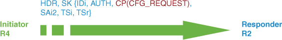
IKEv2:Config data to send:
Config-type: Config-request
Attrib type: ipv4-addr, length: 0
Attrib type: ipv4-netmask, length: 0
Attrib type: ipv4-dns, length: 0
Attrib type: ipv4-dns, length: 0
Attrib type: ipv4-nbns, length: 0
Attrib type: ipv4-nbns, length: 0
Attrib type: app-version, length: 259, data: Cisco IOS Software, Linux Software
(I86BI_LINUX-ADVENTERPRISEK9-M), Version 15.2(2)T2.3, DEVELOPMENT TEST SOFTWARE
Technical Support: http://www.cisco.com/techsupport
Copyright (c) 1986-2012 by Cisco Systems, Inc.
Compiled Thu 08-Nov-12 06:59 by prod_rel_team
Attrib type: ipv4-subnet, length: 0
Attrib type: split-dns, length: 0
Attrib type: banner, length: 0
Attrib type: config-url, length: 0
Attrib type: config-ver, length: 0
Attrib type: backup-gateway, length: 0
Attrib type: def-domain, length: 0
IKEv2:(SA ID = 1):Have config mode data to send
IKEv2:(SA ID = 1):Generate my authentication data
IKEv2:(SA ID = 1):Use preshared key for id R4.cisco.com, key len 5
IKEv2:[IKEv2 -> Crypto Engine] Generate IKEv2 authentication data
IKEv2:[Crypto Engine -> IKEv2] IKEv2 authentication data generation PASSED
IKEv2:(SA ID = 1):Get my authentication method
IKEv2:(SA ID = 1):My authentication method is 'PSK'
IKEv2:(SA ID = 1):Generating IKE_AUTH message
IKEv2:(SA ID = 1):Constructing IDi payload: 'R4.cisco.com' of type 'FQDN'
IKEv2:(SA ID = 1):ESP Proposal: 1, SPI size: 4 (IPSec negotiation),
Num. transforms: 2
3DES Don't use ESN
IKEv2:(SA ID = 1):Building packet for encryption.
Payload contents:
VID IDi AUTH CFG SA TSi TSr NOTIFY(INITIAL_CONTACT) NOTIFY(SET_WINDOW_SIZE) NOTIFY(ESP_TFC_NO_SUPPORT) NOTIFY(NON_FIRST_FRAGS)
IKEv2:(SA ID = 1):Sending Packet [To 10.50.100.2:500/From 10.50.30.4:500/VRF
i0:f0]
Initiator SPI : 5863E01AB3750C92 - Responder SPI : A5EAB51958821403 Message id: 1
IKEv2 IKE_AUTH Exchange REQUEST
Payload contents:
ENCR
IKEv2:(SA ID = 1):Received Packet [From 10.50.100.2:500/To 10.50.30.4:500/VRF
i0:f0]
Initiator SPI : 5863E01AB3750C92 - Responder SPI : A5EAB51958821403 Message id: 1
IKEv2 IKE_AUTH Exchange RESPONSE
Payload contents:
VID IDr AUTH CFG SA TSi TSr NOTIFY(SET_WINDOW_SIZE) NOTIFY(ESP_TFC_NO_SUPPORT)
NOTIFY(NON_FIRST_FRAGS)
IKEv2:(SA ID = 1):Process auth response notify
IKEv2:(SA ID = 1):Searching policy based on peer's identity '10.50.100.2' of type
'IPv4 address'
IKEv2:Searching Policy with fvrf 0, local address 10.50.30.4
IKEv2:Using the Default Policy for Proposal
IKEv2:Found Policy 'default'
IKEv2:(SA ID = 1):Verify peer's policy
IKEv2:(SA ID = 1):Peer's policy verified
IKEv2:(SA ID = 1):Get peer's authentication method
IKEv2:(SA ID = 1):Peer's authentication method is 'PSK'
IKEv2:(SA ID = 1):Get peer's preshared key for 10.50.100.2
IKEv2:(SA ID = 1):Verify peer's authentication data
IKEv2:(SA ID = 1):Use preshared key for id 10.50.100.2, key len 5
IKEv2:[IKEv2 -> Crypto Engine] Generate IKEv2 authentication data
IKEv2:[Crypto Engine -> IKEv2] IKEv2 authentication data generation PASSED
IKEv2:(SA ID = 1):Verification of peer's authenctication data PASSED
IKEv2:Using mlist list1 and username flex for group author request
IKEv2:(SA ID = 1):[IKEv2 -> AAA] Authorisation request sent
IKEv2:(SA ID = 1):[AAA -> IKEv2] Received AAA authorisation response
IKEv2:(SA ID = 1):Received valid config mode data
IKEv2:Config data received:
Config-type: Config-reply
Attrib type: ipv4-addr, length: 4, data: 172.17.100.55
Attrib type: ipv4-subnet, length: 8, data: 172.17.100.2 255.255.255.255
Attrib type: ipv4-dns, length: 4, data: 192.168.2.25
Attrib type: app-version, length: 259, data: Cisco IOS Software, Linux Software (I86BI_LINUX-ADVENTERPRISEK9-M), Version 15.2(2)T2.3, DEVELOPMENT TEST SOFTWARE
Technical Support: http://www.cisco.com/techsupport
Copyright (c) 1986-2012 by Cisco Systems, Inc.
Compiled Thu 08-Nov-12 06:59 by prod_rel_team
Attrib type: backup-gateway, length: 12, data: R1.cisco.com
IKEv2:(SA ID = 1):Set received config mode data
IKEv2:(SA ID = 1):Processing IKE_AUTH message
IKEv2:KMI/verify policy/sending to IPSec:
prot: 3 txfm: 3 hmac 0 flags 8177 keysize 0 IDB 0x0
IKEv2:(SA ID = 1):IKEV2 SA created; inserting SA into database. SA lifetime timer
(86400 sec) started
IKEv2:IKEv2 MIB tunnel started, tunnel index 1
IKEv2:(SA ID = 1):Load IPSEC key material
IKEv2:(SA ID = 1):Checking for duplicate IKEv2 SA
IKEv2:(SA ID = 1):No duplicate IKEv2 SA found
Config-type: Config-set
Attrib type: ipv4-subnet, length: 8, data: 172.17.100.55 255.255.255.255
Attrib type: ipv4-subnet, length: 8, data: 172.18.34.0 255.255.255.0
Attrib type: app-version, length: 259, data: Cisco IOS Software, Linux Software (I86BI_LINUX-ADVENTERPRISEK9-M), Version 15.2(2)T2.3, DEVELOPMENT TEST SOFTWARE
Technical Support: http://www.cisco.com/techsupport
Copyright (c) 1986-2012 by Cisco Systems, Inc.
Compiled Thu 08-Nov-12 06:59 by prod_rel_team
IKEv2:(SA ID = 1):Sending info exch config
IKEv2:(SA ID = 1):Building packet for encryption.
Payload contents:
CFG
IKEv2:(SA ID = 1):Checking if request will fit in peer window
IKEv2:(SA ID = 1):Sending Packet [To 10.50.100.2:500/From 10.50.30.4:500/VRF
i0:f0]
Initiator SPI : 5863E01AB3750C92 - Responder SPI : A5EAB51958821403 Message id: 2
IKEv2 INFORMATIONAL Exchange REQUEST
Payload contents:
ENCR
%LINEPROTO-5-UPDOWN: Line protocol on Interface Tunnel0, changed state to up
%FLEXVPN-6-FLEXVPN_CONNECTION_UP: FlexVPN(flex) Client_public_addr = 10.50.30.4
Server_public_addr = 10.50.100.2 Assigned_Tunnel_addr = 172.17.100.55
R4#
*Oct 28 21:15:58.500: IKEv2:(SA ID = 1):Received Packet [From 10.50.100.2:500/To
10.50.30.4:500/VRF i0:f0]
Initiator SPI : E9514C2B78FD144B - Responder SPI : FEB010A8A5E13415 Message id: 2
IKEv2 INFORMATIONAL Exchange RESPONSE
Payload contents:
CFG
IKEv2:(SA ID = 1):Processing ACK to informational exchange
IKEv2:Config data received:
Config-type: Config-ack
Attrib type: ipv4-subnet, length: 0
IKEv2:(SA ID = 1):Set received config mode data
Understanding IKEv2 Routing Options
FlexVPN supports several VPN types that use dynamic routing protocols to forward traffic that requires IPsec protection. In legacy VPN implementations that used crypto maps, or with some EZVPN deployments, RRI was used to create static routes based on IPsec source and destination proxies (addresses/masks). FlexVPN uses new IKEv2 constructs route set and route accept as described in Table 2a-5.

Section 4: System Hardening and Availability
System or device hardening involves implementing techniques that protect against compromise, resulting in either specific device/system failures or disruption to other network services. The goal of enabling protection and monitoring features on a system is performance predictability and network availability. This section requires implementing and troubleshooting specific hardening features such as control and management plane policing. Features that focus on network availability, such as routing protocol security, monitoring traffic transiting a switch, and securing wireless infrastructure, are also covered.
Solution and Verification for Exercise 4.1: BGP TTL-Security through the Cisco ASA
Skills Tested
![]() Configuring BGP security features; specifically, TTL-Security in Cisco IOS
Configuring BGP security features; specifically, TTL-Security in Cisco IOS
![]() Configuring the Cisco ASA to manipulate TTL values and appear as a hop in the network
Configuring the Cisco ASA to manipulate TTL values and appear as a hop in the network
![]() Understanding basic BGP show commands to aid in troubleshooting and verification
Understanding basic BGP show commands to aid in troubleshooting and verification
Solution and Verification
In this exercise, the eBGP multihop command must be replaced with the newer TTL-Security command, and ASA2 must be configured to appear as an actual routed hop between R6 and R7.
TTL-Security is based on RFC 5082, “Generalized TTL Security Mechanism (GTSM).” eBGP multihop does not protect against attackers spoofing BGP packets with the TTL specifically set so that the BGP peer will see a TTL = 1 and process the packet. This can lead to DoS attacks that target the router CPU. TTL-Security inverts the TTL check so that only BGP packets with a TTL of 255 less the number of hops specified in the TTL-Security command are processed.
Configuring ASA2 to function as a routed hop in the path of IP packets means that ASA2 will decrement the TTL field of those packets. This behavior will have an impact on the hop count requirements of BGP TTL-Security. To determine how to tune this BGP command, you can use traceroute between the BGP neighbors as follows:
R7# traceroute 10.50.70.6
Type escape sequence to abort.
Tracing the route to r6.cisco.com (10.50.70.6)
VRF info: (vrf in name/id, vrf out name/id)
1 10.50.40.20 4 msec * 0 msec
2 10.50.50.5 0 msec 4 msec 8 msec
3 r6.cisco.com (10.50.70.6) 0 msec * 0 msec
With TTL-Security, the BGP packet is sent with a TTL = 255. With two hops in the path between R7 and R6 (ASA2 and SW2), BGP packets will be processed only if the IP packet TTL is 255 − 2 >= 253. Therefore, the hop count parameter used with TTL-Security is configured as
neighbor ip-address ttl-security hops 2
For all verification syntax that follows:
![]() Required output appears in red
Required output appears in red
Verify that ASA2 has been correctly configured to decrement the TTL in IP packets:
R7# traceroute 10.50.70.6
Type escape sequence to abort.
Tracing the route to r6.cisco.com (10.50.70.6)
VRF info: (vrf in name/id, vrf out name/id)
1 10.50.40.20 4 msec * 0 msec
2 10.50.50.5 0 msec 4 msec 8 msec
3 r6.cisco.com (10.50.70.6) 0 msec * 0 msec
The ASA2 service policy should specify the following:
ASA2# show service-policy
. . .
Class-map: set-ttl
Set connection policy: drop 0
Set connection decrement-ttl
To verify whether the TTL-Security hop count is set correctly and BGP packets are being processed, check the state of the BGP connection and that BGP routes have been installed in the BGP route tables on R6 and R7:
R7# show ip bgp neighbors 10.50.70.6 | include state
BGP state = Established, up for 1d21h
Connection state is ESTAB, I/O status: 1, unread input bytes: 0
R7# show ip bgp
BGP table version is 15, local router ID is 172.18.107.7
Status codes: s suppressed, d damped, h history, * valid, > best, i - internal,
r RIB-failure, S Stale, m multipath, b backup-path, x best-external,
f RT-Filter, a additional-path
Origin codes: i - IGP, e - EGP, ? - incomplete
Network Next Hop Metric LocPrf Weight Path
*> 172.18.106.0/24 10.50.70.6 0 0 106 ?
*> 172.18.107.0/24 0.0.0.0 0 32768 ?
R6# show ip bgp
BGP table version is 3, local router ID is 172.18.106.6
Status codes: s suppressed, d damped, h history, * valid, > best, i - internal,
r RIB-failure, S Stale, m multipath, b backup-path, x best-external,
f RT-Filter, a additional-path
Origin codes: i - IGP, e - EGP, ? - incomplete
Network Next Hop Metric LocPrf Weight Path
*> 172.18.106.0/24 0.0.0.0 0 32768 ?
*> 172.18.107.0/24 10.50.40.7 0 0 107 ?
Configuration
Replace
neighbor 10.50.40.7 ebgp-multihop 2
neighbor 10.50.70.6 ebgp-multihop 2
R6
router bgp 106
bgp log-neighbor-changes
redistribute connected route-map bgp
neighbor 10.50.40.7 remote-as 107
neighbor 10.50.40.7 password cisco
neighbor 10.50.40.7 ttl-security hops 2
R7
router bgp 107
bgp log-neighbor-changes
redistribute connected route-map bgp
neighbor 10.50.70.6 remote-as 106
neighbor 10.50.70.6 password cisco
neighbor 10.50.70.6 ttl-security hops 2
ASA2
class-map set-ttl
Match any
policy-map global_policy
class set-ttl
set connection decrement-ttl
Tech Notes
By default, Cisco IOS sends BGP messages to EBGP neighbors with an IP time-to-live (TTL) of 1, implying the BGP peers are adjacent. This restriction can be adjusted with the ebgp-multihop command. With this command, BGP packets can be sent with the TTL at a higher number than 1. Sending BGP messages with a TTL of 1 requires the peer to be directly connected, or the packets will expire in transit. Likewise, a BGP router will only accept incoming BGP messages with a TTL of 1 (or whatever value is specified by ebgp-multihop), which can help mitigate spoofing attacks. However, it is still possible for a remote attacker to adjust the TTL of sent packets so that they appear to originate from a directly connected peer. Spoofing legitimate-looking packets to a BGP router at high volume can lead to a DoS attack.
The solution to this, as discussed in RFC 5082, is to invert the direction in which the TTL is counted. The maximum value of the 8-bit TTL field in an IP packet is 255. Instead of accepting only packets with a TTL set to 1, the BGP router can accept only packets with a TTL of 255 to ensure that the originator really is exactly one hop away. This is accomplished in Cisco IOS with the TTL-Security feature. Only BGP messages with an IP TTL greater than or equal to 255 minus the specified hop count will be accepted. TTL security and EBGP multihop are mutually exclusive; ebgp-multihop is no longer needed when TTL security is in use.
Solution and Verification for Exercise 4.2: Configure and Troubleshoot Control Plane Protection
Skills Tested
![]() Control Plane Protection (CPPr) options
Control Plane Protection (CPPr) options
![]() Understanding how to identify closed-ports on a Cisco IOS device
Understanding how to identify closed-ports on a Cisco IOS device
Solution and Verification
To prevent the unnecessary processing of packets destined to closed ports, CPPr can be tuned to track open and closed ports on the control plane. Control plane protection techniques are applied to the control plane subinterfaces (host, transit, CEF exception). In this case, because we are focusing on the ports that are open and closed on the router itself, the CPPr policy is applied to the host subinterface. It is important that only traffic destined to closed ports be dropped. This requires knowledge of the features and services running on the router. The commands show control-plane host open-ports and show udp are useful for determining the ports currently being used by the host. Note that not all ports appear in the open-ports list. As new applications are added to Cisco IOS, there could be a time lag with respect to adding them to the list of known ports. As such, this exercise requires the administrator to compare the open-ports list against the actual list of services supported by the host. When defining the CPPr policy, the MQC syntax is used with the service policy being applied to the control-plane host subinterface and the port-filter type specified on class maps and policy maps.
For all verification syntax that follows:
![]() Required output appears in red
Required output appears in red
![]() Variable syntax appears in green
Variable syntax appears in green
Determine the ports on R1 that are open and listening:
R1# show control-plane host open-ports
Active internet connections (servers and established)
Prot Local Address Foreign Address Service State
tcp *:22 *:0 SSH-Server LISTEN
tcp *:23 *: Telnet LISTEN
tcp *:8080 *:0 HTTP CORE LISTEN
tcp *:8080 *:0 HTTP CORE LISTEN
udp *:123 *:0 NTP LISTEN
udp *:4500 *:0 ISAKMP LISTEN
udp *:500 *:0 ISAKMP LISTEN
As the preceding output displays, the show control-plane host open-ports command is not displaying UDP/848 for GDOI, which is running as a result of the configuration of GETVPN in Exercise 3.2 in this lab.
Knowing that some ports might be missing from the show control-plane host open-ports output, verify the UDP-based services listening on R1. Note that UDP/848 is an open port that was not displayed by show control-plane host open-ports.
R1# show udp
Proto Remote Port Local Port In Out Stat TTY OutputIF
17 --listen-- 10.50.100.1 123 0 0 1001001 0
17(v6) --listen-- FE80::1 123 0 0 1020001 0
17 --listen-- 10.50.100.1 848 0 0 1001011 0
17(v6) --listen-- FE80::1 848 0 0 1020011 0
17 --listen-- 10.50.100.1 4500 0 0 1001011 0
17(v6) --listen-- FE80::1 4500 0 0 1020011 0
17 --listen-- 10.50.100.1 500 0 0 1001011 0
17(v6) --listen-- FE80::1 500 0 0 1020011 0
17 --listen-- 10.50.100.1 4500 0 0 1001011 0
17(v6) --listen-- FE80::1 4500 0 0 1020011 0
Knowing UDP/848 is not being classified as an open port, and will in fact be deemed a closed port, the traffic of interest defined in the class map must be all closed ports except UDP/848:
R1# show class-map type port-filter
Class Map type port-filter match-all pf-class
Match not port udp 848
Match closed-ports
R1# show policy-map type port-filter
Policy Map type port-filter pf-policy
Class pf-class
drop
R1# show run | section control-plane host
control-plane host
service-policy type port-filter input pf-policy
Configuration
R1
class-map type port-filter match-all pf-class
match not port udp 848
match closed-ports
!
!
policy-map type port-filter pf-policy
class pf-class
drop
control-plane host
service-policy type port-filter input pf-policy
Tech Notes
Specific map (class, policy) types are available for enhancing CPPr.
![]() The port-filtering feature provides for policing/dropping of packets going to closed or nonlistening TCP/UDP ports.
The port-filtering feature provides for policing/dropping of packets going to closed or nonlistening TCP/UDP ports.
![]() Queue thresholding limits the number of packets for a specified protocol that will be allowed in the control plane IP input queue.
Queue thresholding limits the number of packets for a specified protocol that will be allowed in the control plane IP input queue.
The Cisco IOS CLI options are as follows:
class-map type
port-filter Class map for port filter
queue-threshold Class map for queue threshold
policy-map type
port-filter Control-plane tcp/udp port filtering
queue-threshold Control-plane protocol queue limiting
Solution and Verification for Exercise 4.3: Control Plane Protection for IPv6 Cisco IOS
Skills Tested
![]() Control Plane Protection options applied to IPv6 traffic
Control Plane Protection options applied to IPv6 traffic
Solution and Verification
CPPr is applicable to all IP traffic processed by the router control plane. In this question, the policy requirements are to police ICMPv6 traffic that is seen by the CPU, and to apply policing to the default class.
As discussed in Exercise 1.4 of this lab, ICMPv6 messages play an important role in the management of an IPv6 network. When a network supports IPv6 (RFC 2460), the Internet Control Message Protocol version 6 (ICMPv6) (RFC 4443) plays a fundamental role, including being an essential component in establishing and maintaining communications both at the interface level and for sessions to remote nodes. ICMPv6 is to IPv6 what ARP is to IPv4. This is a key point that can be used to identify which control-plane subinterface requires the CPPr service policy. Services such as ARP and ICMPv6 are handled by the CEF-exception subinterface.
This exercise calls for CPPr on essential ICMPv6 messages. Several messages must be allowed on the network. These are discussed in RFC 4890, “Recommendations for Filtering ICMPv6 Messages in Firewall.” Overly aggressive filtering of ICMPv6 by firewalls can have a detrimental effect on the establishment and maintenance of IPv6 communications. This document outlines the messages that should not be filtered and instead will be processed by hosts that are a part of the IPv6 network.
The interesting traffic for the class map comprises all recommended ICMPv6 messages that can be seen by the router. A match of all ICMP types can also be used; however, for purposes of this guide, the administrator should be familiar with specific ICMPv6 message types.
For all verification syntax that follows:
![]() Required output appears in red
Required output appears in red
![]() Variable syntax appears in green
Variable syntax appears in green
Verify the contents of the ICMPv6 access list that will be referenced by the CPPr class map:
R4# show access-list RFC4890
IPv6 access list RFC4890
permit icmp any any echo-reply sequence 10
permit icmp any any echo-request sequence 20
permit icmp any any destination-unreachable sequence 30
permit icmp any any port-unreachable sequence 40
permit icmp any any packet-too-big sequence 50
permit icmp any any time-exceeded sequence 60
permit icmp any any parameter-problem sequence 70
permit icmp any any mld-query sequence 80
permit icmp any any mld-reduction sequence 90
permit icmp any any mld-report sequence 100
permit icmp any any nd-na (23776 matches) sequence 110
permit icmp any any nd-ns (12962 matches) sequence 120
permit icmp any any router-solicitation sequence 130
permit icmp any any router-advertisement sequence 140
Verify whether policing rate, conform and exceed actions, and the CEF exception subinterface have been configured correctly:
R4# show policy-map control-plane cef-exception
Control Plane Cef-exception
Service-policy input: COPPRv6
Class-map: ICMPv6 (match-all)
25142 packets, 2038444 bytes
5 minute offered rate 0 bps, drop rate 0 bps
Match: access-group name RFC4890
police:
cir 8000 bps, bc 1500 bytes
conformed 25142 packets, 2038444 bytes; actions:
transmit
exceeded 0 packets, 0 bytes; actions:
drop
conformed 0000 bps, exceeded 0000 bps
Class-map: class-default (match-any)
264174 packets, 29538421 bytes
5 minute offered rate 0 bps, drop rate 0 bps
Match: any
police:
cir 10000 bps, bc 1500 bytes
conformed 264163 packets, 29536519 bytes; actions:
transmit
exceeded 11 packets, 1902 bytes; actions:
transmit
conformed 0000 bps, exceeded 0000 bps
Configuration
R4
class-map match-all ICMPv6
match access-group name RFC4890
policy-map COPPRv6
class ICMPv6
police 8000 conform-action transmit exceed-action drop
class class-default
police 10000 conform-action transmit exceed-action transmit
ipv6 access-list RFC4890
permit icmp any any echo-reply
permit icmp any any echo-request
permit icmp any any destination-unreachable
permit icmp any any port-unreachable
permit icmp any any packet-too-big
permit icmp any any time-exceeded
permit icmp any any parameter-problem
permit icmp any any mld-query
permit icmp any any mld-reduction
permit icmp any any mld-report
permit icmp any any nd-na
permit icmp any any nd-ns
permit icmp any any router-solicitation
permit icmp any any router-advertisement
control-plane cef-exception
service-policy input COPPRv6
Section 5: Threat Identification and Mitigation
This section requires the implementation of threat identification and mitigation techniques on different Cisco platforms. On a Cisco IOS Router, NetFlow is used to identify possible attack patterns, and this information is then used to build a Flexible Packet Matching (FPM) policy. DHCP activities can be manipulated to launch attacks that are mitigated by methods configured on Cisco Catalyst switches. This section also covers application-specific attack mitigation features on the Cisco ASA.
Solution and Verification for Exercise 5.1: Preventing IP Address Spoofing on the Cisco ASA
Skills Tested
![]() Understanding and configuring mitigation techniques for IP address spoofing
Understanding and configuring mitigation techniques for IP address spoofing
Solution and Verification
Several methods are available on the Cisco ASA to protect against IP address spoofing. You should apply an access list, based on recommendations in RFC 2827, “Network Ingress Filtering”; however, this exercise specifically states that access lists cannot be used to solve the problem.
The simplest solution is to implement Unicast RPF (uRPF) on those interfaces of ASA2 that are likely to be targeted by attackers; namely, the dmz and outside interfaces. uRPF prevents IP address spoofing by accepting only IP packets that arrive on an interface with a source address that is routable via the interface on which the packet was received. The IP routing table is consulted to match the source address to a route and a next-hop interface. If the actual route to the source address of an IP packet is via a different interface than the one on which the packet was received, it is dropped.
For all verification syntax that follows:
![]() Required output appears in red
Required output appears in red
![]() Required tasks appear in indigo
Required tasks appear in indigo
![]() Nonzero/nonnull syntax appears in violet
Nonzero/nonnull syntax appears in violet
To verify whether uRPF has been correctly configured, initiate a ping using the source address of 10.50.50.4 from R4:
R3# ping 10.50.40.7 so lo10
Type escape sequence to abort.
Sending 5, 100-byte ICMP Echos to 10.50.40.7, timeout is 2 seconds:
Packet sent with a source address of 10.50.50.4
When this packet reaches ASA2 on the dmz interface, the IP routing table will be consulted. The route table shows that the route to 10.50.50.0/24 is via the outside interface, not the dmz interface.
C 10.50.50.0 255.255.255.0 is directly connected, outside
If uRPF is enabled on the dmz interface (as well as the outside as another possible attack target), RPF drop counters should be incrementing.
ASA2# show ip verify statistics
interface outside: 0 unicast rpf drops
interface dmz: 9 unicast rpf drops
Configuration
ASA2
ip verify reverse-path int dmz
ip verify reverse-path int outside
Tech Notes
Understanding Unicast Reverse Path Forwarding in Cisco IOS: Technology Overview
Unicast RPF works in one of three different modes: strict mode, loose mode, or VRF mode. Note that not all network devices support all three modes of operation.
When implementing uRPF in strict mode, the packet must be received on the interface that the router would use to forward the return packet. uRPF configured in strict mode can drop legitimate traffic that is received on an interface that was not the router’s choice for sending return traffic. Dropping this legitimate traffic could occur when asymmetric routing paths are present in the network.
When implementing uRPF in loose mode, the source address must appear in the routing table. Administrators can change this behavior by using the allow-default option, which enables the use of the default route in the source verification process. Additionally, a packet that contains a source address for which the return route points to the Null 0 interface will be dropped. An access list can also be specified that permits or denies certain source addresses in uRPF loose mode. Care must be taken when allowing the default route to factor into permitting packets because any route not explicitly mapping the source address of the incoming packet will be covered by the default route. If the allow-default option must be used, it should be combined with an access list to at least block RFC 1918 and bogon addresses as described in RFC 5735 (replaces RFC 3330).
Understanding Unicast Reverse Path Forwarding: Deployment Guidelines
Administrators should use uRPF in strict mode on network interfaces for which all packets received are guaranteed to originate from the subnet assigned to the interface. A subnet composed of end stations or network resources fulfills this requirement. Such a design would be in place for an access layer network or a branch office where there is only one path into and out of the branch network. No other traffic originating from the subnet is allowed, and no other routes are available past the subnet.
uRPF loose mode can be used on an uplink network interface that has a default route associated with it.
uRPF is supported on the Cisco ASA in addition to Cisco IOS; however, there are some differences in configuration and behavior:
![]() Cisco IOS Support: Unicast RPF is enabled on a per-interface basis. The ip verify unicast source reachable-via rx command enables uRPF in strict mode. To enable loose mode, administrators can use the any option to enforce the requirement that the source IP address for a packet must appear in the routing table. The allow-default option may be used with either the rx or any option to include IP addresses not specifically contained in the routing table. The allow-self-ping option should not be used because it could create a denial of service condition. An access list, such as the one that follows, can also be configured to specifically permit or deny a list of addresses through uRPF:
Cisco IOS Support: Unicast RPF is enabled on a per-interface basis. The ip verify unicast source reachable-via rx command enables uRPF in strict mode. To enable loose mode, administrators can use the any option to enforce the requirement that the source IP address for a packet must appear in the routing table. The allow-default option may be used with either the rx or any option to include IP addresses not specifically contained in the routing table. The allow-self-ping option should not be used because it could create a denial of service condition. An access list, such as the one that follows, can also be configured to specifically permit or deny a list of addresses through uRPF:
interface FastEthernet 0/0
ip verify unicast source reachable-via {rx | any} [allow-default]
[allow-self-ping] [list]
Addresses that should never appear on a network can be dropped by entering a route to a null interface. The following command will cause all traffic received from the 10.0.0.0/8 network to be dropped even if uRPF is enabled in loose mode with the allow-default option: ip route 10.0.0.0 255.0.0.0 Null0.
![]() Cisco ASA: uRPF can be configured on the ASA Security Appliance on a per-interface basis with the following global command: ip verify reverse-path interface interface_name.
Cisco ASA: uRPF can be configured on the ASA Security Appliance on a per-interface basis with the following global command: ip verify reverse-path interface interface_name.
Normally, the ASA looks at the destination address only when determining where to forward the packet. uRPF instructs the ASA to also look at the source address; this is why it is called reverse path forwarding.
Unicast RPF is implemented as follows:
![]() ICMP packets are sessionless, so each packet is checked.
ICMP packets are sessionless, so each packet is checked.
![]() UDP and TCP have sessions, so the initial packet requires a reverse route lookup. Subsequent packets arriving during the session are checked using an existing state maintained as part of the session. Noninitial packets are checked to ensure they arrived on the same interface used by the initial packet.
UDP and TCP have sessions, so the initial packet requires a reverse route lookup. Subsequent packets arriving during the session are checked using an existing state maintained as part of the session. Noninitial packets are checked to ensure they arrived on the same interface used by the initial packet.
Understanding Unicast Reverse Path Forwarding: Other Guidelines
Unallocated IP addresses, IP addresses for private internets as mentioned in RFC 1918, and special-use IP addresses as mentioned in RFC 3330(5735) can be a problem when they are used to route packets on the Internet. These addresses can be used to source attacks that could make it difficult or impossible to trace back to the source. Filtering these addresses at the network boundary will provide another layer of security.
Two IETF best current practices (BCP) describe methods for limiting the risk and impact to the network and infrastructure from attacks using spoofed source addresses:
![]() Network Ingress Filtering: Defeating Denial of Service Attacks which employ IP Source Address Spoofing (BCP38)
Network Ingress Filtering: Defeating Denial of Service Attacks which employ IP Source Address Spoofing (BCP38)
![]() Ingress Filtering for Multihomed Networks (BCP84)
Ingress Filtering for Multihomed Networks (BCP84)
Solution and Verification for Exercise 5.2: Monitor and Protect Against Wireless Intrusion Attacks
Skills Tested
![]() Configuring the Cisco Wireless LAN Controller (WLC) to receive the addresses of wireless clients that should be shunned under the instruction of the Cisco IPS sensor (operating as an Intrusion Detection Sensor (IDS)
Configuring the Cisco Wireless LAN Controller (WLC) to receive the addresses of wireless clients that should be shunned under the instruction of the Cisco IPS sensor (operating as an Intrusion Detection Sensor (IDS)
![]() Enabling TLS service on the Cisco IPS sensor
Enabling TLS service on the Cisco IPS sensor
Solution and Verification
This exercise requires the configuration of the Cisco WLC and Cisco IPS sensor. These two devices form a secure client (WLC) to server (IPS) connection using Transport Layer Security (TLS).
The Cisco Intrusion Detection System/Intrusion Prevention System (CIDS/CIPS) instructs controllers to block certain clients from accessing the wireless network when attacks involving these clients are detected at Layer 3 through Layer 7. You can configure IDS sensors to detect various types of IP-level attacks in your network. When the sensors identify an attack, they can alert the controller to shun the offending client. When you add a new IDS sensor, you register the controller with that IDS sensor so that the controller can query the sensor to get the list of shunned clients.
When an IDS sensor detects a suspicious client, it alerts the controller to shun this client.
For all verification syntax that follows:
![]() Required output appears in red
Required output appears in red
![]() Variable syntax appears in green
Variable syntax appears in green
After TLS is enabled on the sensor, hash values derived from the TLS certification on the sensor are calculated. The SHA-1 fingerprint must be manually added to the WLC configuration; it is used to verify the validity of the sensor:
IPS# show tls fingerprint
MD5: D9:DF:83:E4:00:19:68:59:04:DA:B4:CB:6D:77:73:CA
SHA1: 35:AB:35:7C:BA:58:21:24:1D:BC:1F:3A:8A:CB:2E:06:B0:BB:3F:EE
Verify whether fingerprints match and the communications connection is up. The query state should be enabled and the query result should display success. Queries are sent periodically for liveliness.
(WLC) >show wps cids-sensor detail 1
IP Address....................................... 192.168.2.100
Port............................................. 443
Query Interval................................... 60
Username......................................... wlc
Cert Fingerprint................................. SHA1:
35:AB:35:7C:BA:58:21:24:1D:BC:1F:3A:8A:CB:2E:06:B0:BB:3F:EE
Query State...................................... Enabled
Last Query Result................................ Success
Number of Queries Sent........................... 1
Configuration
WLC
config wps cids-sensor add 1 192.168.2.100 wlc 123cisco123
config wps cids-sensor fingerprint 1 sha1 fingerprint -> taken from IPS and will
vary
config wps cids-sensor enable 1
IPS
service web-server
enable-tls true
port 443
exit
ASA1/c1—Must Allow HTTPS (ACL Name Can Be Anything)
access-list 101 permit tcp any any eq 443
access-group 101 in interface outside
Solution and Verification for Exercise 5.3: Identifying and Protecting Against SYN Attacks
Skills Tested
![]() Configuring connection limits on the Cisco ASA to protect against TCP SYN attacks
Configuring connection limits on the Cisco ASA to protect against TCP SYN attacks
![]() Understanding what methods of setting connection limits are available across ASA software versions
Understanding what methods of setting connection limits are available across ASA software versions
Solution and Verification
The solution to this exercise will vary depending on the version of Cisco ASA software being used. In post-8.3 software, maximum connections can no longer be applied on NAT statements (including identity NATs). Class maps, policy maps, and service policies must be used to configure what is also known as TCP-Intercept on the Cisco ASA.
Setting embryonic and max connection limits per client on ASA1 can protect R1 from potential TCP SYN attacks. This type of DoS attack is prevented by rate limiting TCP connections and not allowing incomplete TCP handshakes to consume resources on R1.
For all verification syntax that follows:
![]() Required output appears in red
Required output appears in red
![]() Variable syntax appears in green
Variable syntax appears in green
Verify by checking that the embryonic-conn-max and per-client-max are set on a sample flow from ANY host to the web server 10.50.100.1 on both TCP 80 and 443 ports:
ASA1/c2# show service-policy flow tcp host 0.0.0.0 host 10.50.100.1 eq 80
Global policy:
Service-policy: global_policy
Class-map: protectCAServer
Match: access-list CAServer
Access rule: permit tcp any host 10.50.100.1 eq www
Action:
Input flow: set connection embryonic-conn-max 100 per-client-max 5
ASA1/c2# show service-policy flow tcp host 0.0.0.0 host 10.50.100.1 eq 443
Global policy:
Service-policy: global_policy
Class-map: protectCAServer
Match: access-list CAServer
Access rule: permit tcp any host 10.50.100.1 eq https
Action:
Input flow: set connection embryonic-conn-max 100 per-client-max 5
Configuration
ASA1/c2
access-list CAServer extended permit tcp any host 10.50.100.1 eq www
access-list CAServer extended permit tcp any host 10.50.100.1 eq https
<...>
class-map protectCAServer
match access-list CAServer
<...>
policy-map global_policy
<...>
class protectCAServer
set connection embryonic-conn-max 100 per-client-max 5
!
service-policy global_policy global
Tech Notes
Configuring Maximum Connections
In pre version-8.3, connection limits can be set on service policy flows or using a NAT translation. The following example shows how to migrate a pre-8.3–based configuration to a post-8.3 command format:
! Old Configuration
static (inside,outside) 172.20.1.10 192.168.100.10 netmask 255.255.255.255 tcp 10
20 norandomseq nailed
! Migrated Configuration
access-list acl-conn-param-tcp-01 extended permit tcp host 192.168.100.10 any
class-map class-conn-param-tcp-01
match access-list acl-conn-param-tcp-01
policy-map policy-conn-param-inside
class class-conn-param-tcp-01
set connection per-client-max 10 per-client-embryonic-max 20
random-sequence-number disable
set connection advanced-options tcp-state-bypass
service-policy policy-conn-param-inside interface inside
TCP Intercept and Limiting Embryonic Connections
Limiting the number of embryonic connections protects a device from a potential DoS attack. The ASA uses the per-client limits and the embryonic connection limit to trigger TCP Intercept, which protects inside systems from a DoS attack perpetrated by flooding an interface with TCP SYN packets. An embryonic connection is a connection request that has not finished the necessary three-way handshake between source and destination. TCP Intercept uses the SYN cookies algorithm to prevent TCP SYN-flooding attacks. A SYN-flooding attack consists of a series of SYN packets usually originating from spoofed IP addresses. The constant flood of SYN packets keeps the server SYN queue full, which prevents it from servicing connection requests. When the embryonic connection threshold of a connection is crossed, the ASA acts as a proxy for the server and generates a SYN-ACK response to the client SYN request. When the ASA receives an ACK back from the client, it can then authenticate the client and allow the connection to the server.
Solution and Verification for Exercise 5.4: Using NBAR for Inspection of HTTP Traffic with PAM and Flexible NetFlow
Skills Tested
![]() Configuring NBAR for application inspection
Configuring NBAR for application inspection
![]() Interpreting Cisco IOS debug output for the purpose of identifying NBAR policy parameters
Interpreting Cisco IOS debug output for the purpose of identifying NBAR policy parameters
![]() Configuring basic PKI trustpoints on a Cisco IOS Router
Configuring basic PKI trustpoints on a Cisco IOS Router
![]() Understanding PAM in Cisco IOS
Understanding PAM in Cisco IOS
![]() Configuring NetFlow v9 to track NBAR classification
Configuring NetFlow v9 to track NBAR classification
Solution and Verification
Network-Based Application Recognition (NBAR) is a classification engine that recognizes many protocols and applications, allowing for the enforcement of packet-handling policies at the application level. HTTP traffic can be deep packet inspected, classifying packets by URL, host, or Multipurpose Internet Mail Extension (MIME) type or a combination of these options.
For all verification syntax that follows:
![]() Required output appears in red
Required output appears in red
![]() Required tasks appear in indigo
Required tasks appear in indigo
![]() Nonzero/nonnull syntax appears in violet
Nonzero/nonnull syntax appears in violet
![]() Variable syntax appears in green
Variable syntax appears in green
From the crypto pki debug output, three HTTP fields were identified as the NBAR match criteria; all fields must match, requiring a match-all policy:
Host: 10.50.100.1
Server: cisco-IOS
Content-Type: application/x-x509-ca-cert
These must be included in the class map definition. The class map identifies interesting traffic that is to be policed to ensure bandwidth on R1 is not consumed by any potential attack on R1. The policy map will apply actions to the HTTP fields of interest; in this case, a QoS policy.
SCEP traffic uses TCP/80 as its transport; however, this port should be mapped to TCP/8080. End entities must use this port (defined in the PKI trustpoint URL) for SCEP communications. This port-to-application mapping (PAM) is only one configuration task required to facilitate TCP/8080. The Cisco IOS HTTP server must be running on the CA server and accepting requests on TCP/8080. Additionally, there must be access to R1 through ASA/c2 on TCP/8080.
The final requirement of this exercise is to enable Flexible NetFlow to provide a breakdown of the devices accessing R1. The NetFlow record must contain the following fields:
IPV4 SOURCE ADDRESS
IPV4 DESTINATION ADDRESS
TRNS SOURCE PORT
TRNS DESTINATION PORT
IP PROTOCOL
APPLICATION NAME
interface input
interface output
counter bytes long
counter packets long
ip fragmentation flags
Capitalized fields must be included in the record and are defined by “match” entries. Noncapitalized fields should be included if data is available and are defined by “collect” entries.
This record is then applied to a NetFlow flow monitor along with the requirement to set the cache inactive timeout to 60. The record field application name is used to reference the NBAR applications defined on the router; in this case, HTTP.
NetFlow statistics can be exported to an external NetFlow collector; however, in this case, the internal cache will be used to verify the NetFlow configuration.
Verify the configuration of the HTTP server on R1. End entities will be sending SCEP transactions to TCP/8080 and the HTTP server must be enabled and running on this port.
R1# show ip http server status
HTTP server status: Enabled
HTTP server port: 8080
The PAM mapping can be verified as follows:
R1# show ip port-map http detail
IP port-map entry for application 'http':
tcp 80 Hypertext Transfer Protocol system defined
tcp 8080 user defined
Access to the CA server on R1 must not be blocked by the ASA. Verify whether TCP/8080 traffic is allowed through ASA1/c2:
ASA1/c2# show access-list
access-list 101 line 15 extended permit tcp any host 10.50.100.1 eq 8080
In Exercise 5.3, a policy was configured on ASA1/c2 that limited connections destined to the CA server. This policy must be updated to enforce max connections on TCP/8080; otherwise, SYN attack protection will not be afforded to connections using TCP/8080:
ASA1/c2# show service-policy flow tcp host 0.0.0.0 host 10.50.100.1 eq 8080
Global policy:
Service-policy: global_policy
Class-map: protectCAServer
Match: access-list CAServer
Access rule: permit tcp any host 10.50.100.1 eq 8080
Action:
Input flow: set connection embryonic-conn-max 100 per-client-max 5
Class-map: class-default
Match: any
Action:
Output flow:
Now that access to the CA server is verified, the crypto pki auth ciscoca command should succeed:
R6(config)# crypto pki auth ciscoca
Certificate has the following attributes:
Fingerprint MD5: 1F5A02E4 C2C8230A 56FC15BB CBDFBEF6
Fingerprint SHA1: 99D5D0AA 928B4DD8 7D9E6D98 B3831F1D 796C6A71
% Do you accept this certificate? [yes/no]: no
Verify the R1 NBAR configuration by checking for increasing packet counts on the required match criteria in both directions on Ethernet0/0:
R1# show policy-map int e0/0
Ethernet0/0
Service-policy input: scep
Class-map: scep (match-all)
8 packets, 480 bytes
5 minute offered rate 0 bps, drop rate 0 bps
Match: protocol http mime "application/x-x509-ca-cert"
Match: protocol http server "cisco-IOS"
Match: protocol http host "10.50.100.1"
police:
cir 10000 bps, bc 1500 bytes
conformed 4 packets, 240 bytes; actions:
transmit
exceeded 0 packets, 0 bytes; actions:
drop
conformed 0000 bps, exceeded 0000 bps
Class-map: class-default (match-any)
487 packets, 106808 bytes
5 minute offered rate 0 bps, drop rate 0 bps
Match: any
Service-policy output: scep
Class-map: scep (match-all)
21 packets, 7960 bytes
5 minute offered rate 0 bps, drop rate 0 bps
Match: protocol http mime "application/x-x509-ca-cert"
Match: protocol http server "cisco-IOS"
Match: protocol http host "10.50.100.1"
police:
cir 10000 bps, bc 1500 bytes
conformed 6 packets, 2042 bytes; actions:
transmit
exceeded 0 packets, 0 bytes; actions:
drop
conformed 0000 bps, exceeded 0000 bps
Class-map: class-default (match-any)
520675 packets, 50074219 bytes
5 minute offered rate 0 bps, drop rate 0 bps
Match: any
Verify the Flexible NetFlow configuration as follows:
R1# show flow monitor name SCEP cache format record
Cache type: Normal
Cache size: 4096
Current entries: 7
High Watermark: 7
Flows added: 93
Flows aged: 86
- Active timeout ( 1800 secs) 0
- Inactive timeout ( 60 secs) 86
- Event aged 0
- Watermark aged 0
- Emergency aged 0
IPV4 SOURCE ADDRESS: 10.50.80.6
IPV4 DESTINATION ADDRESS: 10.50.100.1
TRNS SOURCE PORT: 19689
TRNS DESTINATION PORT: 8080
IP PROTOCOL: 6
APPLICATION NAME: port http
interface input: Et0/0
interface output: Null
counter flows: 1
counter bytes long: 273
counter packets long: 3
ip fragmentation flags: 0x00
Configuration
R1
flow record SCEP
match ipv4 protocol
match ipv4 source address
match ipv4 destination address
match transport source-port
match transport destination-port
match application name
collect ipv4 fragmentation flags
collect interface input
collect interface output
collect counter bytes long
collect counter packets long
!
!
flow monitor SCEP
cache timeout inactive 60
record SCEP
ip port-map http port tcp 8080
ip http server
ip http port 8080
class-map match-all scep
match protocol http mime "application/x-x509-ca-cert"
match protocol http server "cisco-IOS"
match protocol http host "10.50.100.1"
policy-map scep
class scep
police 10000 conform-action transmit exceed-action drop
interface Ethernet0/0
service-policy output scep
service-policy input scep
ip flow monitor SCEP input
R6
crypto key gen rsa
crypto pki trustpoint ciscoca
enrollment url http://10.50.100.1:8080
ASA1/c2
access-list 101 extended permit tcp any host 10.50.100.1 eq 8080
access-list CAServer extended permit tcp any host 10.50.100.1 eq 8080
Tech Notes
Configuring a NetfFlow Exporter
In this exercise, we collected NetFlow statistics and cached them making them viewable from the CLI. In practice, NetFlow information should be collected and exported to a flow collector, reducing the resources consumed by the service on the Cisco IOS device.
The following configuration outlines how to configure a flow exporter and apply it to a flow monitor:
flow exporter export-to-scrutinizer*
destination 192.168.2.25
source Ethernet0/0
transport udp 2055
template data timeout 60
flow monitor SCEP
record SCEP
exporter export-to-scrutinizer*
cache timeout active 60
Note
*Scrutinizer is a Cisco certified NetFlow, IPFix, and AVC engine.
Comparing NetFlow Types
NetFlow v5 is the most popular and most basic of all four formats. It displays the classic source and destination IP addresses, source and destination ports, and the bytes count of transferred data. NetFlow v5 added BGP autonomous system information and flow sequence numbers over previous versions. One limitation of NetFlow v5 is that you can only enable ingress flow export on an interface.
NetFlow v9 is an upgrade to NetFlow v5. On top of the traditional flow record of v5, it adds support for technologies such as multicast, IPsec, and Multi-Protocol Label Switching (MPLS). These enhancements are mostly due to the support for templates, which enable the content of the flows to change based on the needs of the user. For example, due to the routers’ capability to perform deep packet inspection, Layer 7 application details can be exported through the use of NBAR. Also, Voice over IP and video traffic metrics, such as jitter, packet loss, and round-trip time, can also be exported. It also added IPv6 support as well as egress flow collection. v9 is supported in Cisco IOS 12.4 and above.
IPFIX is the Cisco proposed standard for IP Flow Information eXport and was designed based on NetFlow v9. It adds support for variable-length strings, which can be used for application visibility and control (AVC) exports (for example, netflix.com, youtube.com, and facebook.com).
Flexible NetFlow is the configuration interface on the router or switch that enables the user to take advantage of NetFlow v9 and IPFIX. Flexible NetFlow (FnF) enables the user to define the elements required in the flow export. Most of the latest Cisco IOS releases support FnF, which can be used to export NetFlow v5, v9, and IPFIX.
Migrating from Traditional Netflow to Flexible Netflow
The following configurations demonstrate NetFlow v5 and Flexible NetFlow:
! Netflow Version 5
interface FastEthernet 0/1
ip flow [ingress|egress]
exit
ip flow-export destination 192.168.9.101 9996
ip flow-export source FastEthernet 0/1
ip flow-export version 5
ip flow-cache timeout active 1
ip flow-cache timeout inactive 15![]()
! Flexible NetFlow
flow exporter FlowExporter1
destination 192.168.9.101
transport udp 9996
export-protocol netflow-v5
source FastEthernet 0/1
flow monitor FlowMonitor1
record netflow ipv4 original-input
exporter FlowExporter1
cache timeout active 1
cache timeout inactive 15
interface FastEthernet 0/1
ip flow monitor FlowMonitor1 [input|output]
Section 6: Identity Management
In this section, you configure the Cisco Identity Services Engine (ISE) and Cisco Secure Access Control Server (ACS) to support identity-based network access and device management using RADIUS and TACACS+. Device command authorization on a Cisco IOS Router is an important method for restricting device access and limiting the potential for attack or inadvertent misconfiguration. Identity-based network access is implemented using Cut-Through Proxy on the Cisco ASA triggered by HTTP traffic. Cisco TrustSec is applied on the Cisco Catalyst switch with the Cisco ISE through the use of MAC Authentication Bypass (MAB) and 802.1X authentication methods enforced on a switch port.
This section covers the Cisco TrustSec (CTS) solution. You will be working with SW1 (10.50.70.4) and SW2 (10.50.70.5) and the Cisco ISE (192.168.2.15). SW1 and SW2 are connected via interface gig1/0/23; this is used for CTS connectivity purposes only.
Solution and Verification for Exercise 6.1: Cisco TrustSec—Dynamically Assigning Secure Group Tagging and SGACLs: 802.1X and MAB
Skills Tested
![]() Enabling 802.1X authentication on the Cisco WLC-managed Cisco AP
Enabling 802.1X authentication on the Cisco WLC-managed Cisco AP
![]() Configuring 802.1X authentication support on the Cisco ISE and Cisco Catalyst switch
Configuring 802.1X authentication support on the Cisco ISE and Cisco Catalyst switch
![]() Defining SGTs and SGACLs on the Cisco ISE
Defining SGTs and SGACLs on the Cisco ISE
![]() Enabling dynamic SGT assignment using authorization profiles on the Cisco ISE
Enabling dynamic SGT assignment using authorization profiles on the Cisco ISE
Solution and Verification
Much of this exercise requires configuration on the ISE in its role as the authentication server.
The Catalyst switch is the authenticator using the Dot1X RADIUS configuration already enabled on SW2 in Lab 1. The authentication mechanism for the IP Phone is still MAB; however, the content of its authorization profile is modified to push the SGT value, which the switch logic uses to identify the IP Phone. Similarly, the Cisco AP (in the role of supplicant) will be authenticated by the ISE using the 802.1X credentials (pushed to the AP from the WLC). The AP’s authorization profile includes an SGT value that is dynamically allocated at successful authorization.
The switch SW2 will use the SGTs to make forwarding decisions based on the SGT values in the security group ACLs (SGACL) that it received dynamically from the ISE. The DACLs per identity used in Lab 1 have been replaced with SGTs and SGACLs.
The solution to this exercise is verified by checking whether the AP and IP Phone have received their SGTs from the ISE. The SGTs and SGACLs are verified by looking at the ISE GUI. In later questions, the actual distribution and enforcement of the SGTs and SGACLs is examined.
For all verification syntax that follows:
![]() Required output appears in red
Required output appears in red
![]() Variable syntax appears in green
Variable syntax appears in green
Part A: Configuring SGTs on the Cisco ISE
Before any Security Group Access (SGA) configuration begins on the Cisco ISE, make sure it is configured as an SGA AAA server, as shown in Figure 2a-18.

Verify the security group list on the Cisco ISE. The unknown group matches all traffic that arrives untagged and cannot be modified. The ISE will assign the actual tag values in ascending order, as shown in Figure 2a-19.

Part B: Dynamically Assigning SGT’s via 802.1X and MAB
After adding the 802.1X credentials on the WLC, verify whether the APs are still associated and the credentials are now displayed in the AP summary; the password will not be displayed.
(WLC) >show ap summ
Number of APs.................................... 2
Global AP User Name.............................. cisco
Global AP Dot1x User Name........................ ciscoAP
AP Name Slots AP Model Ethernet MAC Location Port Country Priority
---------------- ----- ----------------- ----------------- ---------------- ----
AP1cdf.0f94.8063 2 AIR-CAP3502I-A-K9 1c:df:0f:94:80:63 default location 1
AP588d.0959.4921 2 AIR-LAP1262N-A-K9 58:8d:09:59:49:21 default location 1
The following output can be used to verify that authentication and authorization of the AP and IP Phone have been successful. The command clear authentication session interface interface will force reauthentication. Because traffic permissions for the phone are dictated by SGACLs, the DACLs defined in Lab 1 are not required.
SW2# show authentication session int g1/0/14
Interface: GigabitEthernet1/0/14
MAC Address: 0023.eb54.1109
IP Address: Unknown
User-Name: 00-23-EB-54-11-09
Status: Authz Success
Domain: VOICE
Security Policy: Should Secure
Security Status: Unsecure
Oper host mode: multi-auth
Oper control dir: both
Authorized By: Authentication Server
Vlan Policy: 9
SGT: 0004-0
Session timeout: 3600s (local), Remaining: 3509s
Timeout action: Reauthenticate
Idle timeout: N/A
Common Session ID: C0A842420000002E003D9546
Acct Session ID: 0x00000030
Handle: 0x3C00002F
Runnable methods list:
Method State
mab Authc Success
dot1x Not run
SW2# show auth sess int g1/0/18
Interface: GigabitEthernet1/0/18
MAC Address: 588d.0959.4921
IP Address: Unknown
User-Name: ciscoAP
Status: Authz Success
Domain: DATA
Security Policy: Should Secure
Security Status: Unsecure
Oper host mode: multi-auth
Oper control dir: both
Authorized By: Authentication Server
Vlan Policy: N/A
SGT: 0005-0
Session timeout: 3600s (local), Remaining: 3394s
Timeout action: Reauthenticate
Idle timeout: N/A
Common Session ID: 0A3209050000D66D035B9D5E
Acct Session ID: 0x0000D67F
Handle: 0xF10007B5
Runnable methods list:
Method State
dot1x Authc Success
The configuration of the Cisco ISE authorization outputs for the Cisco AP and Cisco IP Phone are shown in Figure 2a-20.
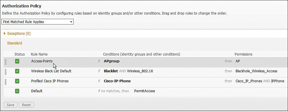
Part C: Create the SGA Egress Policy
Verify whether the SGA egress policies are correctly defined on the ISE. An egress policy will specify what traffic (based on SGACLs) can flow from the source SGT to a destination SGT.
The SGA egress policy matrix should contain two policies. Within each policy, only the protocols and services explicitly defined in the SGACLs should be permitted. All other traffic is denied. The AP and IPPhone to NET70 egress policy is shown in Figure 2a-21. The content of the SGACL applied to the AP and IP Phone is shown in Figure 2a-22.
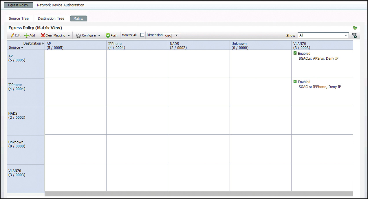

Note that we have defined access policies sourced from the IP Phone and AP switchports; policies can also be explicitly defined for traffic destined to these ports. For this particular question, return traffic will be handled by the default rule, which is permit IP any any, as shown in Figure 2a-23. Changing this rule could impact all policies in the matrix. The default rule is overridden by explicitly defining inbound and outbound egress policies for each combination of source and destination SGTs.

Configuration
WLC
config ap 802.1Xuser add username ciscoAP password CCie123 all
SW2
ip device tracking
interface GigabitEthernet1/0/14
switchport access vlan 99
switchport mode access
switchport voice vlan 9
ip device tracking maximum 2
ip access-group ACL_DEFAULT in
authentication host-mode multi-auth
authentication open
authentication order mab dot1x
authentication priority dot1x mab
authentication port-control auto
authentication periodic
mab
dot1x pae authenticator
spanning-tree portfast
interface GigabitEthernet1/0/18
switchport access vlan 77
switchport mode access
ip device tracking maximum 1
ip access-group ACL_DEFAULT in
authentication host-mode multi-auth
authentication open
authentication port-control auto
authentication periodic
dot1x pae authenticator
Tech Notes
IP Device Tracking
When configuring a static cts enforcement vlan-list, or dynamically assigning SGTs on a port, IP device tracking must be configured globally and on the port where dynamic assignment is being applied. When active hosts are detected, the switch adds the following entries to an IP device tracking table:
![]() IP address of host
IP address of host
![]() MAC address of host
MAC address of host
![]() VLAN of the host
VLAN of the host
![]() The interface on which the switch detected the host
The interface on which the switch detected the host
![]() The state of the host (Active or Inactive)
The state of the host (Active or Inactive)
The host added to the IP device tracking table is monitored with periodic ARP probes. Hosts that fail to respond are removed from the table.
Solution and Verification for Exercise 6.2: Cisco TrustSec—NDAC and MACsec
Skills Tested
![]() Implementing NDAC
Implementing NDAC
![]() Configuring seed and nonseed devices for NDAC
Configuring seed and nonseed devices for NDAC
![]() Configuring MACsec between Catalyst switches using 802.1X and SAP
Configuring MACsec between Catalyst switches using 802.1X and SAP
![]() Creating an NDAC authorization policy on the Cisco ISE
Creating an NDAC authorization policy on the Cisco ISE
![]() Configuring the Cisco Catalyst switch for AAA/RADIUS to create a Cisco TrustSec domain
Configuring the Cisco Catalyst switch for AAA/RADIUS to create a Cisco TrustSec domain
Solution and Verification
This exercise covers setting up the network to support a Cisco TrustSec (CTS) domain. In Exercise 6.1, the basis for SGA was configured on the ISE, and two network devices were provisioned with SGTs. To apply and distribute TrustSec policy elements, such as SGTs and SGACLs, CTS-capable devices such as switches first must be admitted into the CTS domain. This is the purpose of Network Device Admission Control (NDAC). The first switch to be provisioned in the domain is known as the seed device. It must have access to the RADIUS server and will act as a relay for nonseed devices. A nonseed device does not need to have a specific configuration to locate the AAA servers to use with NDAC. Instead, the list is downloaded from the seed device. However, the nonseed device still must be added to the ISE as a TrustSec network access device. In production networks, the seed device is generally a Nexus 7k or Cat 6500; nonseed devices are access switches like the 3750-X or Cisco IOS routers like the ISR G2s and ASRs. The seed switches push SGA policy elements to the nonseed devices dynamically, eliminating the need to manually define access policies on every network device.
In this lab topology, 3750-X switches are both seed and nonseed devices. At press time, the 3k series does not support full SGA functionality; specifically, IP to SGT mappings cannot be dynamically pushed to these switches. For this reason, we are dynamically assigning SGTs at the port (see Exercise 6.1) and manually defining secure group mappings manually on the switches (see Exercise 6.3).
The other important note about this exercise is that SW1 is being configured for NDAC and, although it will receive policy from SW2, due to the layout of the lab topology, we will not be using the policy on SW1. The interface between SW1 and SW2 is solely to illustrate how to implement CTS. In a customer environment, the nonseed switches would be downstream from the seed. The connection between SW1 and SW2 for CTS is simulating a downstream relationship.
For all verification syntax that follows:
![]() Required output appears in red
Required output appears in red
![]() Required tasks appear in indigo
Required tasks appear in indigo
![]() Nonzero/nonnull syntax appears in violet
Nonzero/nonnull syntax appears in violet
1. Configure SW1 and SW2 as network access devices on the ISE, as illustrated in Figure 2a-24. Note the addresses being used on SW1 and SW2. SW2 will have a route to the ISE (192.168.2.15). SW1 does not require direct access to, or a RADIUS configuration for, the ISE because it will send requests via SW2.
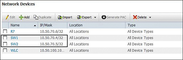
2. Configure SW1 and SW2 for SGA and NDAC.
The SGA settings will enable SGT and SGACL information to be pushed to the devices. The SGA Protected Access Credential (PAC) is used to provide protected access credentials to a member of the CTS domain; without authorized credentials, devices cannot be admitted to the CTS domain. PAC file provisioning is shown in Figure 2a-25. The device ID and password must match those added on the device itself using the cts device-id command, which is illustrated later in this solution.

Note there is the ability to manually generate the PAC file on the ISE and distribute it to NDAC devices out of band. This is not required here because the PAC will automatically be distributed securely using Extensible Authentication Protocol-Flexible Authentication through Secure Tunnelling (EAP-FAST).
EAP-FAST comprises three basic phases:
a. Phase 0: The PAC is initially distributed to the client.
b. Phase 1: Using the PAC, a secure tunnel is established.
c. Phase 2: The client is authenticated via the secure tunnel.
Figure 2a-26 shows the configuration required for provisioning the static IP-SGT mapping list from ISE to the network device. At press time, this feature was not supported on the 3750-X switch, so this figure is included for future reference.

3. Create a network authorization policy for the switches on the ISE, as illustrated in Figure 2a-27.
SW1 and SW2 must be assigned an SGT and authorized to join the NDAC trusted domain. The switches get assigned a SGT so that packets originating from the device are tagged and can also be subject to SGACL filtering.
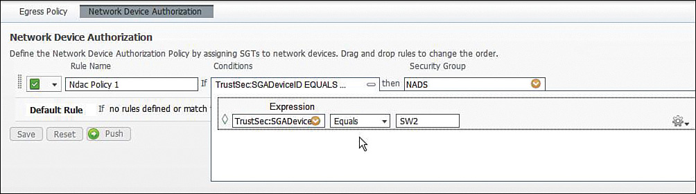
4. Prepare SW1 and SW2 to receive the PAC using AAA.
The AAA support for CTS involves using RADIUS over TLS. This “secure” RADIUS uses automatic PAC provisioning as a low overhead method to send PAC metadata and control information to clients. PAC provisioning is used with EAP-FAST to establish a TLS tunnel in which client credentials are verified.
On the seed device, ensure that RADIUS is correctly configured; both SW1 and SW2 require the AAA commands listed:
Configure AAA authentication for 802.1X using the following command:
aaa authentication dot1x default group radius
Configure AAA accounting for 802.1X using the following command:
aaa accounting dot1x default group radius
Configure AAA network authorization:
aaa authorization network MLIST group radius
SW2 as the seed also must be configured to point to the RADIUS server (ISE):
radius-server host 192.168.2.15 auth-port 1812 acct-port 1813 pac key
cisco123
SW2 also requires
cts authorization list MLIST
On both the seed and nonseed devices, enter the cts device id name command and password cisco123 to immediately begin the PAC file download from the switch exec prompt (the command format can vary depending on the device platform):
cts device-id SW2 password cisco123
cts device-id SW1 password cisco123
Verify whether SW2 has received the PAC files. SW1 has been bootstrapped to receive its credentials from the ISE; however, before this can occur, a MACsec protected and 802.1X authenticated connection must be established between SW1 and SW2 (see Step 6 that follows).
SW2# show cts pac
AID: E716C410120149EFB247059C52D745D0
PAC-Info:
PAC-type = Cisco Trustsec
AID: E716C410120149EFB247059C52D745D0
I-ID: SW2
A-ID-Info: Identity Services Engine
Credential Lifetime: 02:52:52 UTC Nov 24 2013
PAC-Opaque: 000200A80003000100040010E716C410120149EFB247059C52D745D00006008C0003010097E3F0A137617E7D755A
8EA45EE33B73000000135217589B00093A80EF958D003DD12E00CA36774CD161C3CEBA98A8D1C71BF4ADE26FBB21
73B45E219072916142E2332A5A84C2679B628DE62224AB8E4F6449074773E914E0B5F4CD684557A6748A09E75045
D0D7544E74AF085E6D35F3A1BBBC2AFFD5DDC28FA0185BF67A7708F2AF0DC22B241E
Refresh timer is set for 2y34w
5. The supplicant SW1 receives its PAC.
When the link between the supplicant (SW1) and authenticator (SW2) comes up, the ISE will authenticate SW1 using EAP-FAST. SW1 receives a PAC from the ISE containing a shared key and an encrypted token to be used for future secure communications with the authentication server.
Verify whether SW1 has received its PAC file from the ISE:
SW1# show cts pac
AID: E716C410120149EFB247059C52D745D0
PAC-Info:
PAC-type = Cisco Trustsec
AID: E716C410120149EFB247059C52D745D0
I-ID: SW1
A-ID-Info: Identity Services Engine
Credential Lifetime: 22:03:34 UTC Nov 24 2013
PAC-Opaque: 000200A80003000100040010E716C410120149EFB247059C52D745D00006008C00030100236058BADC2408055D44
558F6023ABC6000000135217589B00093A80EF958D003DD12E00CA36774CD161C3CE4FA82A29C82F2D1FCFA79CCA
91BFBA8759EAE57250386392FDE86B896EBEF0CB68713C84E178D962F6C77A484E580BBF4726F4094DE7F945FB4E
1D528B10D7598C1428E458CD1D87530F390D46D749C05E1A2C1D95024BDC2BB35D1D
Refresh timer is set for 2y34w
6. Verify the secured connection between SW1 and SW2.
Based on the identity of the authenticated device, in this case SW2, the ISE can provide authorization policies to each of the devices linked to SW2. The ISE provides the identity of each peer to the other, and each peer then applies the appropriate policy for the link. Verify whether each switch has been authenticated using DOT1X. Also, check whether SGTs have been assigned. When both sides of the link support encryption, Security Association Protocol (SAP) is used to negotiate policy parameters to establish a secure connection between the authenticator (SW2) and the supplicant (SW1).
SW2# show cts interface
Global Dot1x feature is Enabled
Interface GigabitEthernet1/0/23:
CTS is enabled, mode: DOT1X
IFC state: OPEN
Authentication Status: SUCCEEDED
Peer identity: "SW1"
Peer's advertised capabilities: "sap"
802.1X role: Authenticator
Reauth period configured: 240 (locally configured)
Reauth period per policy: 86400 (server configured)
Reauth period applied to link: 86400 (server configured)
Reauth starts in approx. 0:23:54:45 (dd:hr:mm:sec)
Authorization Status: SUCCEEDED
Peer SGT: 2:NADS
Peer SGT assignment: Trusted
SAP Status: SUCCEEDED
Version: 2
Configured pairwise ciphers:
gcm-encrypt
null
no-encap
Replay protection: enabled
Replay protection mode: STRICT
Selected cipher: gcm-encrypt
Propagate SGT: Enabled
Cache Info:
Cache applied to link : NONE
Statistics:
authc success: 17
authc reject: 1
authc failure: 1
authc no response: 0
authc logoff: 0
sap success: 17
sap fail: 0
authz success: 3
authz fail: 1
port auth fail: 0
L3 IPM: disabled.
Dot1x Info for GigabitEthernet1/0/23
-----------------------------------
PAE = AUTHENTICATOR
QuietPeriod = 60
ServerTimeout = 0
SuppTimeout = 30
ReAuthMax = 2
MaxReq = 2
TxPeriod = 30![]()
SW1# show cts interface
Global Dot1x feature is Enabled
Interface GigabitEthernet1/0/23:
CTS is enabled, mode: DOT1X
IFC state: OPEN
Authentication Status: SUCCEEDED
Peer identity: "SW2"
Peer's advertised capabilities: "sap"
802.1X role: Supplicant
Reauth period applied to link: Not applicable to Supplicant role
Authorization Status: SUCCEEDED
Peer SGT: 2:NADS
Peer SGT assignment: Trusted
SAP Status: SUCCEEDED
Version: 2
Configured pairwise ciphers:
gcm-encrypt
null
no-encap
Replay protection: enabled
Replay protection mode: STRICT
Selected cipher: gcm-encrypt
Propagate SGT: Enabled
Cache Info:
Cache applied to link : NONE
Statistics:
authc success: 1
authc reject: 1
authc failure: 1
authc no response: 0
authc logoff: 0
sap success: 1
sap fail: 0
authz success: 4
authz fail: 0
port auth fail: 0
L3 IPM: disabled.
Dot1x Info for GigabitEthernet1/0/23
-----------------------------------
PAE = SUPPLICANT
StartPeriod = 30
AuthPeriod = 30
HeldPeriod = 60
MaxStart = 3
Credentials profile = CTS-ID-profile
EAP profile = CTS-EAP-profile
SGA policies are propagated over the secure link, protected by MACsec. Verify
counters are incrementing.
SW1# show cts macsec counters int g1/0/23
CTS Security Statistic Counters:
rxL2UntaggedPkts = 0
rxL2NotagPkts = 23
rxL2SCMissPkts = 0
rxL2CTRLPkts = 0
rxL3CTRLPkts = 0
rxL3UnknownSAPkts = 0
rxL2BadTagPkts = 0
txL2UntaggedPkts = 0
txL2CtrlPkts = 0
txL3CtrlPkts = 0
txL3UnknownSA = 0
SA Index : 0
rxL2ReplayfailPkts = 0
rxL2AuthfailPkts = 0
rxL2PktsOK = 3220
rxL3AuthCheckFail = 0
rxL3ReplayCheckFail = 0
rxL2SAMissPkts = 23
rxL3EspGcm_Pkts = 0
rxL3InverseCheckfail = 0
txL3Protected = 0
SW2# show cts macsec counters interface g1/0/23
CTS Security Statistic Counters:
rxL2UntaggedPkts = 0
rxL2NotagPkts = 186
rxL2SCMissPkts = 0
rxL2CTRLPkts = 0
rxL3CTRLPkts = 0
rxL3UnknownSAPkts = 0
rxL2BadTagPkts = 0
txL2UntaggedPkts = 0
txL2CtrlPkts = 0
txL3CtrlPkts = 0
txL3UnknownSA = 0
SA Index : 0
rxL2ReplayfailPkts = 0
rxL2AuthfailPkts = 0
rxL2PktsOK = 4367
rxL3AuthCheckFail = 0
rxL3ReplayCheckFail = 0
rxL2SAMissPkts = 186
rxL3EspGcm_Pkts = 0
rxL3InverseCheckfail = 0
txL3Protected = 0
txL2Protected = 2816
To verify whether both SW1 and SW2 have been authorized into the CTS domain, and also to verify the policies created on the ISE in Exercise 6.1 part A and C, the environment-data output should display the SGT list:
SW2# show cts environment-data
CTS Environment Data
====================
Current state = COMPLETE
Last status = Successful
Local Device SGT:
SGT tag = 2-00:NADS
Server List Info:
Installed list: CTSServerList1-0001, 1 server(s):
*Server: 192.168.2.15, port 1812, A-ID E716C410120149EFB247059C52D745D0
Status = ALIVE
auto-test = TRUE, keywrap-enable = FALSE, idle-time = 60 mins, deadtime
= 20 secs
Security Group Name Table:
0-00:Unknown
2-00:NADS
3-00:NET70
4-00:IPPhone
5-00:AP
Environment Data Lifetime = 120 secs
The cat3k does not support the downloading of the IP to SGT mapping table (other switches, such as the Nexus 7k and Cat 6k, can dynamically receive this table from the ISE). To provide the mapping table to the 3750-X, the IP-SGT bindings are created using a combination of manual configured mappings and mappings learned via SGT assignment during device authentication and the IP tracking mechanism. The mapping table can then be verified as follows:
SW2# show cts role-based sgt all
Active IP-SGT Bindings Information
IP Address SGT Source
============================================
10.50.9.5 2 INTERNAL
10.50.9.6 4 LOCAL
10.50.40.7 7 VLAN
10.50.50.5 2 INTERNAL
10.50.70.4 3 VLAN
10.50.70.5 2 INTERNAL
10.50.70.6 3 VLAN
10.50.77.5 2 INTERNAL
10.50.77.8 5 LOCAL
10.50.99.5 2 INTERNAL
The SGT source values in the output list are defined as follows:
![]() INTERNAL: Any IP address on the switch receives the same SGT assigned to the switch by the NDAC authorization policy.
INTERNAL: Any IP address on the switch receives the same SGT assigned to the switch by the NDAC authorization policy.
![]() LOCAL: SGTs assigned to devices via port authorization, such as 802.1X and MAB, are mapped to the IP addresses of those devices. If a device disconnects from the switchport, this change in state must be reflected in the IP-SGT binding table; this required IP device tracking is enabled on those ports.
LOCAL: SGTs assigned to devices via port authorization, such as 802.1X and MAB, are mapped to the IP addresses of those devices. If a device disconnects from the switchport, this change in state must be reflected in the IP-SGT binding table; this required IP device tracking is enabled on those ports.
![]() VLAN: These bindings are created as a result of the cts enforcement command with the vlan-list option. IP device tracking monitors information, such as IP addresses, of devices seen on each VLAN in the list. This ensures the IP-SGT bindings are dynamically maintained.
VLAN: These bindings are created as a result of the cts enforcement command with the vlan-list option. IP device tracking monitors information, such as IP addresses, of devices seen on each VLAN in the list. This ensures the IP-SGT bindings are dynamically maintained.
![]() CLI: Manually defined static device bindings.
CLI: Manually defined static device bindings.
![]() SXP: Bindings learned from an SXP speaker peer.
SXP: Bindings learned from an SXP speaker peer.
Finally, SGACL information downloaded from the ISE (as defined in Part C of Exercise 6.1 in this lab) can be inspected on SW2. Note that the default permission of permit ip as shown in Figure 2a-23 has also been downloaded.
SW2# show cts role-based permission
IPv4 Role-based permissions default:
Permit IP-00
IPv4 Role-based permissions from group 4:IPPhone to group 3:NET70:
IPPhone-30
Deny IP-00
IPv4 Role-based permissions from group 5:AP to group 3:NET70:
APSrvs-40
Deny IP-00
SW2# show access-list
Role-based IP access list APSrvs-40 (downloaded)
10 permit icmp
20 permit udp dst eq 5246
30 permit udp dst eq 5247
Role-based IP access list Deny IP-00 (downloaded)
10 deny ip
Role-based IP access list IPPhone-30 (downloaded)
10 permit tcp dst eq 2000
20 permit tcp dst eq www
30 permit udp dst eq bootps
40 permit udp dst eq domain
50 permit tcp src eq www
60 permit icmp
70 permit udp dst eq tftp
Role-based IP access list Permit IP-00 (downloaded)
10 permit ip
To verify SGACL enforcement on the switchports, check for incrementing counters:
SW2# show cts role-based counters
Role-based IPv4 counters
# '-' in hardware counters field indicates sharing among cells with identical
policies
From To SW-Denied HW-Denied SW-Permitted HW-Permitted
4 3 0 107 0 71
5 3 0 0 0 40
* * 0 0 8595 14282
Configuration
SW1
aaa authentication dot1x default group radius
aaa authorization network MLIST group radius
!
!
dot1x system-auth-control
interface GigabitEthernet1/0/23
switchport trunk encapsulation dot1q
switchport mode trunk
cts dot1x
sap mode-list gcm-encrypt null no-encap
radius-server vsa send authentication
SW2
aaa authentication dot1x default group radius
aaa authorization network MLIST group radius
aaa accounting dot1x default start-stop group radius
dot1x system-auth-control
aaa server radius dynamic-author
client 192.168.2.15
server-key cisco123
cts authorization list MLIST
cts role-based enforcement
cts role-based enforcement vlan-list 9,70,77
interface GigabitEthernet1/0/23
switchport trunk encapsulation dot1q
switchport mode trunk
cts dot1x
sap mode-list gcm-encrypt null no-encap
radius-server attribute 44 include-in-access-req default-vrf
radius-server attribute 6 on-for-login-auth
radius-server attribute 8 include-in-access-req
radius-server attribute 25 access-request include
radius-server dead-criteria time 10 tries 5
radius-server host 192.168.2.15 auth-port 1812 acct-port 1813 pac key cisco123
radius-server vsa send accounting
radius-server vsa send authentication
Tech Notes
Protected Access Credential
The PAC is a unique shared credential used to mutually authenticate client and server. It is associated with a specific client username and a server A-ID. A PAC removes the need for Public Key Infrastructure (PKI) and digital certificates.
Creating a PAC consists of the following steps:
1. Server A-ID maintains a local key (master key) that is known only by the server.
2. When a client identity (I-ID) requests a PAC from the server, the server generates a randomly unique PAC key and PAC-Opaque field for this client.
3. The PAC-Opaque field contains the randomly generated PAC key along with other information, such as user identity and key lifetime.
4. PAC Key, I-ID, and Lifetime in the PAC-Opaque field are encrypted with the master key.
5. A PAC-Info field that contains the A-ID is created.
6. The PAC is distributed or imported to the client automatically or manually.
MACsec Overview
MACsec provides Layer 2 encryption on the LAN. It also encapsulates and protects the metadata field that carries the SGT.
Currently, two keying mechanisms are available: Security Association Protocol (SAP) and MAC Security Key Agreement (MKA). SAP is a proprietary Cisco keying protocol used between Cisco switches. MKA is an industry standard and is currently used between endpoints and Cisco switches. Both use 128-bit AES-GCM (Galois/Counter Mode) symmetric encryption, and provide replay attack protection of every frame.
Downlink MACsec describes the encrypted link between an endpoint and the switch. The encryption between the endpoint and the switch is handled by the MKA keying protocol. This requires a MACsec-capable switch and a MACsec-capable supplicant on the endpoint (such as the Cisco AnyConnect Network Access Manager). The encryption on the endpoint can be handled in hardware (if the endpoint possesses the correct hardware) or in software using the main CPU for the encryption and decryption.
To configure the switch for Downlink MACsec, enter the following:
interface X
switchport access vlan 10
switchport mode access
switchport voice vlan 99
ip access-group ACL-ALLOW in
authentication event fail action next-method
authentication event server dead action authorize vlan 2274
authentication event server alive action reinitialize
authentication event linksec fail action next-method
authentication host-mode multi-domain
authentication open
authentication order dot1x mab
authentication priority dot1x mab
authentication port-control auto
authentication violation restrict
macsec mka default-policy
mab
dot1x pae authenticator
dot1x timeout tx-period 10
spanning-tree portfast
end
Uplink MACsec is the term used to describe encrypting the link between the switches with 802.1AE. At the time this guide was written, the switch-to-switch encryption uses Cisco’s proprietary SAP instead of MKA, which is used with the Downlink MACsec. The encryption is still the same AES-GCM-128 encryption used with both Uplink and Downlink MACsec.
Uplink MACsec can be achieved manually or dynamically. Dynamic MACsec requires 802.1X between the switches and is covered in this question.
Manual configuration will encrypt the interswitch links without requiring the entire domain of trust, the way that NDAC does. It also removes the dependency on ISE for the link keying, similar to how an IPSec tunnel can be built using preshared keys.
To configuring the switch for Manual Uplink MACsec, enter the following:
interface TenGigabitEthernet1/1/1
description Cat6K Ten1/5
no switchport
ip address 10.1.48.2 255.255.255.252
ip authentication mode eigrp 1 md5
ip authentication key-chain eigrp 1 EIGRP
load-interval 60
cts manual
policy static sgt 2 trusted
sap pmk 0000000000000000000000000000000000000000000000000000000000000026
mode-list
gcm-encrypt
MACsec Sequence in an NDAC Domain
When the link between a supplicant and an authenticator first comes up, the following sequence of events typically occurs:
1. Authentication: Using NDAC, ISE authenticates a device using EAP-FAST before allowing it to join the network. During the EAP-FAST exchange, ISE creates and sends a unique PAC to the supplicant switch (the switch attempting to join the NDAC domain). That PAC contains a shared key and an encrypted token to be used for future secure communications with the authentication server.
2. Authorization: Based on the identity information of the supplicant switch, ISE provides authorization policies to each of the linked peers. The authentication server provides the identity of each peer to the other, and each peer then applies the appropriate policy for the link.
3. Security Association Protocol (SAP) negotiation: When both sides of a link support encryption, the supplicant and the authenticator negotiate the necessary parameters to establish a security association (SA) and encrypt the traffic.
When all three steps are complete, the authenticator changes the state of the link from the unauthorized (blocking) state to the authorized state, and the supplicant switch becomes a member of the NDAC trusted domain.
Solution and Verification for Exercise 6.3: Cisco TrustSec—SGT Exchange Protocol over TCP
Skills Tested
![]() Manual definition of SGTs per host and per VLAN on the Cisco Catalyst switch
Manual definition of SGTs per host and per VLAN on the Cisco Catalyst switch
![]() Configuring Secure Group Tag Exchange Protocol over TCP (SXP) on switches and Cisco IOS routers
Configuring Secure Group Tag Exchange Protocol over TCP (SXP) on switches and Cisco IOS routers
![]() Enabling SXP on the Cisco WLC
Enabling SXP on the Cisco WLC
Solution and Verification
SXP connections are required to forward SGT to IP address bindings to devices that do not use NDAC to join the CTS domain and do not support native SGT tagging. SXP is a peering protocol that uses TCP as its transport. Peers form a relationship in which one takes the role of the speaker and pushes bindings to the listener peer. The listener can then use the binding information in its own policies. For example, when an SXP connection is established between SW2 and R6, the zone-based firewall configuration in Exercise 1.5 can be completed. SXP connections can be formed between adjacent (next hop) peers, or the TCP-transported information can be routed to other devices.
In Exercise 6.2, the IP-SGT table on SW2 comprised different binding types: VLAN, LOCAL, and INTERNAL. This exercise requires CLI bindings to be created on SW2. These are manually defined static bindings that, along with the other binding types, can be distributed to SXP peers listening to SW2.
For all verification syntax that follows:
![]() Required output appears in red
Required output appears in red
Verify whether SW2 is the designated speaker for the SXP connections between the WLC, SW1, and R6.
Options are available for a default password and default source IP address. If a password is set, it must match the password configured on the peer device.
SW2# show cts sxp connection
SXP : Enabled
Highest Version Supported: 3
Default Password : Not Set
Default Source IP: Not Set
Connection retry open period: 120 secs
Reconcile period: 120 secs
Retry open timer is not running
----------------------------------------------
Peer IP : 10.50.70.4
Source IP : 10.50.70.5
Conn status : On
Conn version : 3
Local mode : SXP Speaker
Connection inst# : 1
TCP conn fd : 2
TCP conn password: none
Duration since last state change: 1:15:43:12 (dd:hr:mm:sec)
----------------------------------------------
Peer IP : 10.50.70.6
Source IP : 10.50.70.5
Conn status : On
Conn version : 2
Local mode : SXP Speaker
Connection inst# : 1
TCP conn fd : 1
TCP conn password: none
Duration since last state change: 911:12:20:18 (dd:hr:mm:sec)
Total num of SXP Connections = 2
Devices SW1 and R6 are listeners receiving IP-SGT binding from SW2. Additional bindings may be configured on SW1 and R6; however, they will not be propagated to SW2. If SW1 and R6 take the role of an SXP speaker, binding can be propagated to a listener. In addition, R6 is listening to the WLC, which can propagate bindings for wireless clients as they are authorized.
SW1# show cts sxp connection
SXP : Enabled
Highest Version Supported: 3
Default Password : Not Set
Default Source IP: 10.50.70.4
Connection retry open period: 120 secs
Reconcile period: 120 secs
Retry open timer is not running
----------------------------------------------
Peer IP : 10.50.70.5
Source IP : 10.50.70.4
Conn status : On
Conn version : 3
Local mode : SXP Listener
Connection inst# : 1
TCP conn fd : 1
TCP conn password: none
Duration since last state change: 1:15:42:01 (dd:hr:mm:sec)
Total num of SXP Connections = 1
R6# show cts sxp connection
SXP : Enabled
Default Password : Set
Default Source IP: Not Set
Connection retry open period: 120 secs
Reconcile period: 120 secs
Retry open timer is not running
----------------------------------------------
Peer IP : 10.50.70.5
Source IP : 10.50.70.6
Conn status : On
Conn version : 2
Local mode : SXP Listener
Connection inst# : 2
TCP conn fd : 1
TCP conn password: none
Duration since last state change: 1:22:48:33 (dd:hr:mm:sec)
----------------------------------------------
Peer IP : 10.50.100.10
Source IP : 10.50.80.6
Conn status : On
Conn version : 2
Local mode : SXP Listener
Connection inst# : 1
TCP conn fd : 2
TCP conn password: default SXP password
Duration since last state change: 0:00:10:14 (dd:hr:mm:sec)
Total num of SXP Connections = 2
The WLC can only take on the role as an SXP speaker, as shown in Figure 2a-28.
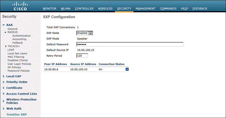
SXP status on the WLC is also displayed using the CLI.
(WLC) >show cts sxp connections
Total num of SXP Connections..................... 1
SXP State........................................ Enable
Peer IP Source IP Connection Status
--------------- --------------- -----------------
10.50.80.6 10.50.100.10 On
The status of the SXP connections has been verified as enabled. The last task in this exercise required the definition of manual static entries on SW2. Check that all entries outlined in Task 4 have been added to the IP-SGT binding table.
SW2# show cts role-based sgt all
Active IP-SGT Bindings Information
IP Address SGT Source
============================================
10.50.9.5 2 INTERNAL
10.50.9.6 4 LOCAL
10.50.30.3 12 CLI
10.50.30.4 12 CLI
10.50.40.7 7 VLAN
10.50.50.5 2 INTERNAL
10.50.50.20 14 CLI
10.50.70.4 2 CLI
10.50.70.5 2 INTERNAL
10.50.70.6 3 VLAN
10.50.77.5 2 INTERNAL
10.50.77.8 5 LOCAL
10.50.80.50 16 CLI
10.50.99.5 2 INTERNAL
10.50.100.1 15 CLI
10.50.100.2 15 CLI
10.50.100.10 15 CLI
192.168.2.25 18 CLI
IP-SGT Active Bindings Summary
============================================
Total number of VLAN bindings = 2
Total number of CLI bindings = 9
Total number of LOCAL bindings = 2
Total number of INTERNAL bindings = 5
Total number of active bindings = 18
All entries learned from SW2 will be of type SXP. The manually defined entry for 10.50.70.4 will be overridden by the internal binding on SW1.
SW1# sho cts role-based sgt all
Active IP-SGT Bindings Information
IP Address SGT Source
============================================
10.50.9.5 2 SXP
10.50.9.6 4 SXP
10.50.30.3 12 SXP
10.50.30.4 12 SXP
10.50.40.7 7 SXP
10.50.50.5 2 SXP
10.50.50.20 14 SXP
10.50.70.4 2 INTERNAL
10.50.70.5 2 SXP
10.50.70.6 3 SXP
10.50.77.5 2 SXP
10.50.77.8 5 SXP
10.50.80.50 16 SXP
10.50.99.5 2 SXP
10.50.100.1 15 SXP
10.50.100.2 15 SXP
10.50.100.10 15 SXP
192.168.1.5 2 INTERNAL
192.168.2.5 2 INTERNAL
192.168.2.25 18 SXP
192.168.100.1 2 INTERNAL
IP-SGT Active Bindings Summary
============================================
Total number of SXP bindings = 17
Total number of INTERNAL bindings = 4
Total number of active bindings = 21
Ensure that R6 has all bindings from SW2. The SGTs will be used in the ZFW configuration in Exercise 1.5.
R6# show cts role-based sgt all
Active IP-SGT Bindings Information
IP Address SGT Source
============================================
10.50.9.5 2 SXP
10.50.9.6 4 SXP
10.50.30.3 12 SXP
10.50.30.4 12 SXP
10.50.40.7 7 SXP
10.50.50.5 2 SXP
10.50.50.20 14 SXP
10.50.70.4 2 SXP
10.50.70.5 2 SXP
10.50.70.6 3 SXP
10.50.77.5 2 SXP
10.50.77.8 5 SXP
10.50.80.50 16 SXP
10.50.99.5 2 SXP
10.50.100.1 15 SXP
10.50.100.2 15 SXP
10.50.100.10 15 SXP
192.168.2.25 18 SXP
IP-SGT Active Bindings Summary
============================================
Total number of SXP bindings = 18
Total number of active bindings = 18
Configuration
SW2
cts role-based sgt-map 10.50.30.3 sgt 12
cts role-based sgt-map 10.50.30.4 sgt 12
cts role-based sgt-map 10.50.50.20 sgt 14
cts role-based sgt-map 10.50.70.4 sgt 2
cts role-based sgt-map 10.50.80.50 sgt 16
cts role-based sgt-map 10.50.100.1 sgt 15
cts role-based sgt-map 10.50.100.2 sgt 15
cts role-based sgt-map 10.50.100.10 sgt 15
cts role-based sgt-map 192.168.2.25 sgt 18
cts role-based sgt-map vlan-list 70 sgt 3
cts role-based sgt-map vlan-list 40 sgt 7
cts role-based enforcement
cts role-based enforcement vlan-list 9,40,70,77
cts sxp enable
cts sxp connection peer 10.50.70.6 password none mode local
cts sxp connection peer 10.50.70.4 password none mode local
!
SW1
cts sxp enable
cts sxp default source-ip 10.50.70.4
cts sxp connection peer 10.50.70.5 password none mode local listener
R6
cts sxp enable
cts sxp connection peer 10.50.70.5 password none mode local listener
WLC
config cts sxp enable
config cts sxp default password cisco
config cts sxp connection peer 10.50.80.6
Tech Notes
SXP on the Cisco WLC
SXP is supported only in centrally switched networks that have central authentication.
![]() By default, SXP is supported for APs that work in local mode only.
By default, SXP is supported for APs that work in local mode only.
![]() The controller always operates in the speaker mode.
The controller always operates in the speaker mode.
![]() The configuration of the default password should be consistent for both controller and the switch.
The configuration of the default password should be consistent for both controller and the switch.
![]() Fault tolerance is not supported because fault tolerance requires local switching on APs.
Fault tolerance is not supported because fault tolerance requires local switching on APs.
![]() SXP is supported for both IPv4 and IPv6 clients.
SXP is supported for both IPv4 and IPv6 clients.
![]() Static IP-SGT mapping for local authentication of users is not supported.
Static IP-SGT mapping for local authentication of users is not supported.
![]() IP-SGT mapping requires authentication with external identity servers.
IP-SGT mapping requires authentication with external identity servers.
![]() SXP is supported on the following security policies only:
SXP is supported on the following security policies only:
![]() WPA2-dot1x
WPA2-dot1x
![]() WPA-dot1x
WPA-dot1x
![]() 802.1x (Dynamic WEP)
802.1x (Dynamic WEP)
![]() MAC filtering using RADIUS servers
MAC filtering using RADIUS servers
![]() Web authentication using RADIUS servers for user authentication
Web authentication using RADIUS servers for user authentication
Summary of Secure Group Access Features
![]() 802.1AE Encryption (MACsec): Protocol for 802.1AE-based wire-rate hop-to-hop Layer 2 encryption. Between MACsec-capable devices, packets are encrypted on egress from the sending device, decrypted on ingress to the receiving device, and in the clear within the devices. This feature is available only between 802.1AE-capable devices.
802.1AE Encryption (MACsec): Protocol for 802.1AE-based wire-rate hop-to-hop Layer 2 encryption. Between MACsec-capable devices, packets are encrypted on egress from the sending device, decrypted on ingress to the receiving device, and in the clear within the devices. This feature is available only between 802.1AE-capable devices.
![]() Network Device Admission Control (NDAC): NDAC is an authentication process by which each network device in the TrustSec domain can verify the credentials and trustworthiness of its peer device. NDAC uses an authentication framework based on IEEE 802.1x port-based authentication and uses EAP-FAST as its EAP method. Authentication and authorization by NDAC results in SAP negotiation for 802.1AE encryption.
Network Device Admission Control (NDAC): NDAC is an authentication process by which each network device in the TrustSec domain can verify the credentials and trustworthiness of its peer device. NDAC uses an authentication framework based on IEEE 802.1x port-based authentication and uses EAP-FAST as its EAP method. Authentication and authorization by NDAC results in SAP negotiation for 802.1AE encryption.
![]() Security Association Protocol (SAP): SAP is a Cisco proprietary key exchange protocol between switches. After NDAC switch-to-switch authentication, SAP automatically negotiates keys and the cipher suite for subsequent switch-to-switch MACsec encryption between TrustSec peers. The protocol description is available under a nondisclosure agreement.
Security Association Protocol (SAP): SAP is a Cisco proprietary key exchange protocol between switches. After NDAC switch-to-switch authentication, SAP automatically negotiates keys and the cipher suite for subsequent switch-to-switch MACsec encryption between TrustSec peers. The protocol description is available under a nondisclosure agreement.
![]() Security Group Tag (SGT): An SGT is a 16-bit single label showing the security classification of a source in the TrustSec domain. It is appended to an Ethernet frame or an IP packet.
Security Group Tag (SGT): An SGT is a 16-bit single label showing the security classification of a source in the TrustSec domain. It is appended to an Ethernet frame or an IP packet.
![]() SGT Exchange Protocol (SXP), including SXPv2: With SXP, devices that are not TrustSec-hardware capable can receive SGT attributes for authenticated users or devices from the Cisco Access Control System (ACS). The devices then forward the source IP-to-SGT binding to a TrustSec-hardware capable device for tagging and security group ACL (SGACL) enforcement.
SGT Exchange Protocol (SXP), including SXPv2: With SXP, devices that are not TrustSec-hardware capable can receive SGT attributes for authenticated users or devices from the Cisco Access Control System (ACS). The devices then forward the source IP-to-SGT binding to a TrustSec-hardware capable device for tagging and security group ACL (SGACL) enforcement.