Chapter 5
Open Shortest Path First (OSPF)
THE CCNP ENCOR EXAM OBJECTIVES COVERED IN THIS CHAPTER INCLUDE THE FOLLOWING: Most importantly, you'll learn how to configure OSPF and several key features, including authentication, passive interfaces, default route injection, inter-area summarization, and route filtering. The exercises at the conclusion of the chapter align with the examples in the chapter. I recommend reading the chapter first, and then performing the exercises on your own, falling back on the chapter text as your guide in case you get stuck. Regardless of how you approach the exercises, be sure to complete them in your own Cisco lab. When it comes to understanding routing protocols, there's no substitute for hands-on configuring and troubleshooting. OSPF is a link-state protocol, meaning that all routers in an autonomous system (AS) share the states of their local network links—their link-state information—with one another using link-state advertisements (LSAs). An LSA includes but isn't limited to the following key pieces of information: Using the LSAs it receives, each router builds its own link-state database (LSDB), which it uses to form a map of the entire network. Using this network map, the router uses the Dijkstra Shortest Path First (SPF) algorithm to calculate the best path to each IP prefix. Assuming all OSPF routers receive the same LSAs, they'll all end up with identical copies of the LSDB, and the end result is that all routers arrive at the same routing decisions. But that's a big assumption. And in a large network with potentially thousands of routers, this doesn't sound very scalable in terms of bandwidth and memory. For example, if you had just 100 routers, and a single interface on one of those routers went down, it would require flooding link-state updates to the other 99 routers. The size of the LSDB grows exponentially with the number of interfaces, and that just doesn't scale. To deal with this, OSPF lets you create a two-level routing hierarchy by breaking the AS up into areas. Within an area, or intra-area, routers exchange full link-state information with one another, giving each router the flexibility to choose the truly shortest path to any prefix in the area. However, between areas, or inter-area, the link-state information that's shared is limited, in terms of both size and frequency. OSPF area numbers can be written in 32-bit dotted decimal notation like an IP address, but they usually are just integers to avoid confusion with RIDs and IP addresses. Area 0 (or Area 0.0.0.0), also known as the backbone area, always exists in every AS. It sits at the top of the routing hierarchy and connects to all other non-backbone areas. Routers in non-backbone areas can't route directly to one another but must always go through Area 0. Also, Area 0 can't be split—that is, links in Area 0 must follow a continuous path with no other areas in between. Nonzero areas must border Area 0. For example, a router may have an interface in Area 1 (or Area 0.0.0.1), another interface in Area 20 (or Area 0.0.0.20), and yet another interface in Area 0. As long as the router borders Area 0, it can have multiple interfaces in nonzero areas. OSPFv2 (RFC 2328) is the version of OSPF for IPv4. To control the frequency of LSAs and to keep each router's LSDB manageable, OSPFv2 includes six LSA types: You need to know only types 1 through 3 for the ENCOR exam. Types 4, 5, and 7 are beyond the scope of this book; however, I'm going to briefly cover types 4 and 5 because you're likely to see them in other exams or on a lab. Router LSAs contain the IP prefix of each connected interface. Each OSPF router always generates type 1 Router LSAs and floods them to all OSPF routers in the area. When you have more than two routers connected to a broadcast network, Router LSAs become redundant, if not problematic. For example, suppose the following three routers are connected to one another: R1 would send three LSAs each to R2 and R3—one LSA for each router. R2 would likewise send three LSAs each to R1 and R3, and so on. This is ridiculously wasteful because they're all connected to the same broadcast segment! And you can imagine how much worse the problem would become if you were to add a few more routers. To deal with this, OSPF includes another LSA type: the type 2 Network LSA. OSPF avoids the aforementioned absurd problem by using type 2 Network LSAs. These come into play when routers are connected to a broadcast (or multiaccess) network. Simply put, the type 2 Network LSA describes the subnet they're connected to. A designated router (DR) collects type 1 LSAs from other OSPF routers on the broadcast segment and combines them into a type 2 Network LSA that describes all the routers on the segment. It then sends the type 2 Network LSA to its OSPF neighbors. Suppose that R1 from the preceding example is the DR. Instead of every router flooding a type 1 LSA to every other router, R2 and R3 instead send their type 1 LSAs only to R1, the DR. R1 generates a type 2 network LSA that advertises the 192.168.1.0/24 subnet, and it sends this LSA to R2 and R3. When OSPF routers in a broadcast domain form an adjacency, they elect a DR. Each router interface has a configurable priority value, which is 1 by default. The router with the highest interface priority on the segment becomes the DR. If there's a tie, the router with the highest RID wins. We'll cover the election process in more detail—and how you can manipulate it—a bit later in this chapter. Whether routers attempt to elect a DR depends on the configured interface network type. The network type describes the nature of the interface and can be one of the following: OSPF intelligently chooses the network type based on the interface type. An Ethernet interface by default will be broadcast, whereas a serial link will be point-to-point. However, you can manually configure an interface as point-to-point or broadcast. Make sure both ends are configured with the same network type. Network types don't have to match in order to form an adjacency, but they do need to match in order for the routers to exchange routes. If you enable OSPF on a loopback interface, OSPF considers it a loopback network type, and always advertises the loopback IPv4 address with a /32 subnet mask. If you want to advertise the loopback interface with its configured subnet mask, change the network type to point-to-point. A type 3 Summary LSA includes inter-area prefixes—prefixes from other areas. The purpose of the summary LSA is to summarize the type 1 and type 2 LSAs from an area and repackage them in a single summary LSA to share with other areas. This reduces the amount of inter-area flooding. A router that's connected to two or more areas is called an area border router (ABR). ABRs are responsible for generating type 3 summary LSAs. When traffic moves inter-area—that is, from one OSPF area to another—it must pass through an ABR. This is the two-tier hierarchical design in action. It does create suboptimal routing in which inter-area routing isn't necessarily going to take the shortest path, but the benefit is that OSPF becomes more scalable. For example, take a look at the layer 3 topology in Figure 5.1. R2 connects Areas 0 and 23, making it an ABR. R2 takes the type 1 and 2 LSAs from Area 0 and creates a type 3 network summary LSA that it floods into Areas 23 and 27. Figure 5.1 An OSPF topology An ASBR redistributes routes between OSPF and another routing protocol, such as EIGRP or Border Gateway Protocol (BGP). An ASBR may also redistribute static or connected routes. The routes the ASBR redistributes into OSPF are called external routes, and the ASBR advertises them using type 5 AS External LSAs. The type 5 LSA describes the external prefix and the address of the next hop to reach it. The type 4 ASBR Summary LSA is generated by an ABR and tells routers in other areas how to reach the next hop listed in the type 5 AS External LSA. Unlike type 1, 2, and 3 LSAs that remain within an area, type 5 AS External LSAs get flooded across all normal OSPF areas. A Cisco router or layer 3 switch can have multiple OSPF processes, each with its own link-state database and routing topology. Each OSPF process has a process number that's locally significant to the router. One router can use OSPF process number 1, whereas its adjacent neighbor can use process number 2. Internal to the router, OSPF processes are separate. Different OSPF processes on a router don't share an LSDB, but it is possible to configure redistribution between them. Before two OSPF routers can exchange LSAs, they need to form an adjacency. Each OSPF router has an RID, which is formatted like an IPv4 address, even though it's not. You can configure the RID to be any 32-bit dotted-decimal number between 0.0.0.1 and 255.255.255.255. OSPF routers communicate using IP protocol number 89, so they don't use TCP or UDP. When you enable OSPF on an interface, the router sends Hello messages to the multicast address 224.0.0.5, which is the All OSPF Routers multicast address. These Hello messages are how OSPF routers discover each other, and they also function as keepalives to detect a down OSPF neighbor. On broadcast and point-to-point interfaces, routers send Hello packets every 10 seconds by default. The Hello timer determines the frequency at which the Hellos are sent. If an OSPF router doesn't receive a Hello from a neighbor, it will wait four times the Hello timer before it considers the neighbor down and drops the adjacency. This is determined by the dead time, which by default is 40 seconds (four times the Hello interval of 10 seconds). Hello and Dead timers must match in order for routers to form and maintain an adjacency. The MTUs on both routers’ interfaces must match as well. When two OSPF routers establish an adjacency over a point-to-point interface, they exchange LSAs with each other by sending them to the multicast address 224.0.0.5. However, if the routers are connected to a broadcast network, they elect a DR and send their LSAs to the DR by sending them to the DR multicast address 224.0.0.6. The DR will then get the LSAs to the other routers by sending them to the 224.0.0.5 address. Again, this limits flooding of redundant LSAs. An OSPF adjacency can take one of seven states: In the following example, we'll configure OSPF on routers R1, R2, and R3, shown in Figure 5.1. Area 0 includes the interfaces in the 10.0.12.0/30 subnet on both R1 and R2. Area 23 includes the link between R2 and R3 in the 10.0.23.0/29 subnet. In order for a pair of routers to form an OSPF adjacency, their interfaces need to be in the same subnet. Let's start with R1: We'll turn on debugging so we can see Hello messages. Let's enable the OSPF process using process number 1. We'll set the RID to 1.1.1.1. The RID doesn't have to be an IP address, but it must be between 0.0.0.1 and 255.255.255.255. Next, let's enable OSPF on the GigabitEtherneti0/0 interface which has the address 10.0.12.1, placing it in area 0. The 0.0.0.0 wildcard mask is like an inverse subnet mask, matching only the given IP. address. This ensures OSPF isn't enabled on any other interfaces. Moving on to R2: You can manually view all OSPF neighbor adjacencies using the show ip ospf neighbor command, which will show you the DR status for each neighbor. Because both routers have Ethernet interfaces, they participate in a DR election, even though they're the only two routers on the subnet. This adds a negligible amount of time to the time it takes to form an adjacency. In this case, R1 is listed as the backup DR (BDR). By process of elimination, we can infer that R2 is the DR. Notice that the remaining Dead Time is listed as 35 seconds, which just happens to be where the timer was when the show command was run. Recall that the Dead Time interval is 40 seconds (four times the Hello interval). This is how long R2 will wait for a Hello from R1 before considering the adjacency down. Because the Hello timer is 10 seconds, the Dead Time value should never drop below 30 seconds. It would be more appropriate to call the DR election process a game of musical chairs. The first OSPF router to become active on a subnet becomes the DR for the subnet. The second OSPF router on the subnet becomes the BDR. The election process comes into play when the DR disappears. When that happens, the router with the highest OSPF interface priority will be elected the new DR. By default, all routers have an interface priority of 1, with an allowable range of 0 to 255. If the priorities are tied, the router with the highest RID will be elected the new DR, with the next lowest RID becoming the BDR. The interface priority is configurable per interface, letting you control which router on a subnet is elected as the DR. For example, in the 10.0.12.0/30 subnet you have R1 and R2. If you prefer R2 as the DR for the subnet, you can configure it with the highest priority of 255, as shown here: You can verify the priority as follows: Keep in mind that this doesn't ensure that R2 will always be the DR. If R1 comes up first, it will elect itself as the DR (musical chairs, remember?). However, there is a way to make sure R2 always becomes the DR. If a router has an interface priority of 0, it will never be elected as a DR. Hence, we can configure R1 with an interface priority of 0, ensuring that R2 is always the DR. To test this, we'll clear the OSPF process on R2, forcing it to momentarily drop its adjacency with R1: R2 advertises itself as the DR, but it waits 40 seconds (the Dead Time interval) for another router to advertise itself as the BDR. Because R1 doesn't advertise itself as a DR or a BDR, it will take 40 seconds for R1 and R2 to form a full adjacency. Let's verify that R2 is the DR: The last line of the output indicates that there's no BDR. That's because R1 has a priority of 0, so it will never advertise itself as a DR or BDR. R2 is the DR, and R1 is listed as DROTHER, indicating it's neither a DR nor a BDR, but just an OSPF router that has an adjacency with the DR. Remember that non-DRs don't exchange LSAs with one another. LSAs carry a lot of redundant information, so before we dig into the individual LSA details, let's first get a bird's-eye view of R2's entire LSDB. Refer to Figure 5.1 as you read through the output. R2 is connected to Area 0 and Area 23, making it an ABR, so it's going to have quite a few LSAs. The output is broken down into LSA types by area. The link ID uniquely identifies each LSA, and ADV Router indicates the RID of the router that generated the LSA. Let's view the type 1 Router LSAs for area 0. Remember that at this point, we have only two routers, each with a single connected interface, so we should expect to see only two Router LSAs, one from R1 and another from R2. On a broadcast network, the DR generates and sends a type 2 Network LSA describing the IP subnet as well as the routers attached to it. Now let's configure the adjacency between R2 and R3 in Area 23. To illustrate what a point-to-point adjacency looks like, we'll configure the interfaces connecting R2 and R3 as the OSPF point-to-point network type. This will prevent R2 and R3 from attempting to elect a DR. Now let's configure R3. Let's view the type 1 Router LSAs in R3's LSDB. Keep in mind that it contains type 1 Router LSAs only from R2 and R3 since they're the only routers in Area 23. In a bizarre twist, you'll notice that each router actually generates and sends two Router LSAs into Area 23. The reason for this is convoluted and well beyond the scope of the ENCOR exam, but I'll touch on it in a moment. Historically, point-to-point links were serial links that used HDLC or PPP. An interface connected to such a link didn't even need an address. One router would just drop data onto the wire, and it would come out the other end. However, most connections today are Ethernet, which requires using MAC addresses, even if only between two directly connected routers. So, we have to assign an IP subnet to every Ethernet link, even if it's physically point-to-point. OSPF calls this subnet a stub network, and it advertises it using a type 2 Network LSA. Summary LSAs are generated by an ABR, in this case R2. Therefore, from R2 we can view the Summary LSAs it advertises into Area 0 and Area 23. To put it all together, let's take a look at R3's LSDB. It has only one Summary LSA. R3 funnels this information to the IP routing table to generate the router's RIB. Without seeing the IP routing table, you can figure out from the Summary LSA what the route will look like. The destination subnet is 10.0.12.0/30 and the next hop will be R2's interface address. Notice that the route has an administrative distance (AD) of 110. All OSPF-learned routes, whether inter-area, intra-area, or external, have the same AD. Let's run a traceroute to R1's interface address (10.0.12.1). As we expected, the path goes through R2 to R1. Because the traceroute worked, we can also conclude that R1 has learned a Summary LSA for R3's interface subnet (10.0.23.0/29). However, it's always a good idea to verify your configurations. Let's check R1: R1 has a Summary LSA for the 10.0.23.0/29 subnet that it learned from R2. It uses this to build its router RIB, as shown: OSPF offers two ways to control which routers become part of an OSPF topology: These two methods aren't mutually exclusive. You can use either or both. The primary goal of authentication is to prevent OSPF routers from being accidentally or maliciously added to a network. OSPF offers three types of authentication: Configuring interface authentication requires configuring a shared key on both routers. If both routers don't have the same authentication type and password, they won't form an adjacency. In this example, we'll configure R2 and R7 to use interface authentication using the MD5 authentication type, starting with R2: Cryptographic authentication is a cryptic reference to MD5 authentication. Now let's configure R7: Finally, let's verify that R7 is receiving Router and Network LSAs from R2: Area authentication is just a shortcut way to enable authentication on all interfaces in an area. However, it doesn't save you much typing because you still have to specify a shared secret on each interface. Configuring area authentication is a lot like configuring interface authentication. To illustrate, let's configure area 0 authentication on R1 and R2 using MD5, beginning with R1: And R2: The adjacency comes up immediately. To verify that area authentication is enabled, do the following: It's always a good idea to make sure the new configurations didn't break anything, so let's verify that R2 still has all the adjacencies it's supposed to have: There are instances where you want an OSPF router to advertise a prefix for a subnet but don't want the router to form an OSPF adjacency on that subnet. A common example of this is if you have a subnet that's dedicated to servers or clients. None of these host devices should be running OSPF, but someone accidentally launching some open source OSPF software or putting a router in the wrong VLAN could cause an undesired adjacency to form. To avoid this dilemma, you can configure an OSPF interface to be passive. As a passive interface, OSPF will advertise the prefix for that interface but will not form an adjacency with other routers on the subnet. Let's configure R1's Gi0/1 interface facing R4 as a passive interface. This is done not under the interface configuration itself but under the OSPF router configuration. R1 does generate a Router LSA containing the 10.0.14.0/29 network as a stub network. Other routers in Area 0 will thus learn about the subnet. To illustrate, let's look at R2's routing table: You're already familiar with default routes. Often, they're manually configured as static routes. But in a large, dynamic routing topology, manually configuring static routes can be a nightmare, not just because it's a lot of work, but because it can bring about all sorts of unintended consequences, including routing loops. Having OSPF advertise a default route into a normal area is simple. The first step is to create a static default route. As a rule, a router must have a route in its IP routing table to advertise it. We'll configure a static default route on R1 pointing to 203.0.113.2 as the next hop: Next, we instruct OSPF to inject this static default route: Notice that there's no indication of an area. In fact, it's not possible to specify an area because an injected default route is advertised as a type 5 External LSA, which is flooded to all normal areas. A brief view of the LSDB confirms this: To further confirm, let's check R3's routing table: Once again, R1 must have the static default route configured in order to advertise it. If we were to remove the route, it would cease advertising the type 5 External LSAs, and the other OSPF routers in the topology would likewise lose the injected default route. Earlier I mentioned that type 3 Summary LSAs don't refer to summarizing multiple IP prefixes into a larger prefix. However, you can configure an ABR to summarize inter-area routes. R2 is an ABR bordering Area 0 and Area 23. It's advertising three type 3 Summary LSAs into Area 23: These three subnets are generated from Router LSAs in Area 0. R2 packages them as type 3 Summary LSAs and advertises them into Area 23. We'll configure R2 to summarize these three subnets as 10.0.0.0/19 and advertise only the summary route. Notice that the command specifies Area 0 rather than Area 23. That's because the command specifies the source of the routes to summarize rather than the destination. This means that R2 will summarize the routes from Area 0 into Area 23, but it will not summarize the routes from Area 23 into Area 23. Let's verify that R2 is now advertising only the summary into Area 23: Consequently, R3 in Area 23 should have the summarized route but none of the component routes: Let's configure R2 not to advertise any prefixes that fall in the 10.0.0.0/19 range: R2 should cease sending any type 3 Summary LSAs into Area 23. The best way to verify this is from R3: R3 has no Summary LSAs. Consequently, it doesn't have a route for any of the prefixes in the 10.0.0.0/19 range: If you want more granular control over what prefixes are advertised inter-area, you can use a prefix list. Let's configure R2 not to advertise into Area 0 a Summary LSA for the 10.0.23.0/29 prefix. At this point, R2 shouldn't be advertising any Summary LSAs into Area 0 or Area 23. Hence, there should be no Summary LSAs in its LSDB. You've learned how to perform inter-area filtering at an ABR, but there are times when you may want to filter prefixes within an area. OSPF is a link-state protocol, so every router in an area must have an identical copy of the LSDB. However, there's no requirement that every router must install every LSA in its routing table! You can use distribute lists to prevent a router from installing an OSPF-learned route. R3 is learning a default route via a type 5 External LSA. We'll use a distribute list to prevent it from installing a default route. R3 is still learning the prefix from R2, and it still exists in the LSDB, but it's not installed in the IP routing table: Not only that, if we were to later add another router to Area 23, R3 would continue to share this External LSA. Link-state advertisements are the currency of OSPF. Not only do they carry router and prefix information, but also each OSPF router uses them to independently form a map of the network. OSPF routers form adjacencies at layer 2 and exchange LSAs. LSA types 1–4 remain in an area, whereas LSA type 5 is flooded to all normal areas. On a broadcast network, one router is elected as the DR and is responsible for receiving type 1 Router LSAs and using them to generate type 2 Network LSAs. On a point-to-point network, routers exchange type 1 Router LSAs directly. Configuring OSPF requires placing an interface into an area using the network statement. Rather than specifying the interface directly, you specify the subnet that the link resides in. This makes it easy to enable OSPF on a single interface or all interfaces. You can enable OSPF Area 0 on all interfaces using the network 0.0.0.0 0.0.0.0 area 0 command. Know how OSPF adjacencies form. How adjacencies form depends on the network type, which can be broadcast or point-to-point. Know how to configure the network type and understand how it impacts LSA exchanges and neighbor states. Understand the purposes of the various LSA types. The variety of OSPF LSA types isn't to make your life difficult, but to make OSPF more scalable. Understand what information each LSA type carries and why it exists. Be able to configure OSPF. You should be able to configure OSPF and its key features from scratch. A crucial part of configuration is verification, so be able to confirm that your configuration works as expected. Know how to read the LSDB. Each router uses its LSDB to build the IP routing table. Being able to read and understand the link-state database on a router is an important troubleshooting skill. Exercise 5.1 Configure the layer 2 topology shown in Figure 5.2. Address the interfaces according to the layer 3 topology in Figure 5.1. Figure 5.2 Layer 2 topology Exercise 5.2 Configure OSPF Area 0 between R1 and R2 and Area 23 according to the IPv4 topology diagram in Figure 5.1. Don't enable OSPF on any other interfaces. Use the following RIDs: Exercise 5.3 Configure OSPF Area 0 between R2 and R7 according to the IPv4 topology diagram in Figure 5.1. Assign R7 the RID 7.7.7.7. Configure interface authentication between R2 and R7. Exercise 5.4 Configure area authentication for OSPF Area 0. Remember to configure it on all interfaces in Area 0. You can find the answers in the appendix. How can you ensure that a router becomes a DR for a specific subnet? Which command will ensure a router never becomes a DR or a BDR? What's the administrative distance of OSPF inter-area routes? What IP address and protocol number does OSPF use to send Hello packets? Which of the following must match for OSPF routers to form an adjacency? What LSA type is advertised to all normal areas? An OSPF router has one interface in Area 51 and no interfaces in any other areas. Which of the following areas can it not have another interface in? Which of the following LSAs reduces flooding in a broadcast domain? Which of the following suggests the absence of a type 2 Network LSA? Which of the following is true of a type 3 Summary LSA? An OSPF router bordering areas 0 and 1 redistributes EIGRP routes into OSPF. Which two of the following describe this router? OSPF router R1 has a single interface with the IP address 1.0.0.1/24. It has two full adjacencies: one with a DR with a RID of 1.0.0.2 and another with a BDR with a RID of 1.0.0.3. Which of the following values can you configure for the OSPF RID on R1? Which of following must match for two routers to form a full OSPF adjacency? Router R1 has interfaces in Area 0, Area 7, and Area 12. Router R2 is connected to Area 7, and router R3 is connected to Area 12. The routers have no other connected interfaces. Which of the following is true of this topology? Assuming everything is properly configured for a broadcast network, which state do OSPF neighbors stay in if neither is a DR or a BDR? In which OSPF state do routers first exchange full link-state information? What hashing algorithm does OSPF cryptographic authentication use? Which of the following OSPF router commands enables MD5 authentication for all router interfaces in Area 2? Which of the following is not a valid OSPF authentication type? Which two commands make Gi0/3 an OSPF passive interface?
 OSPF is one of the most popular interior gateway protocols (IGPs) in use today. It was originally designed as a replacement for the simple Router Information Protocol (RIP), but it scales better and converges faster. OSPF is without a doubt the most complex IGP you'll use. In this chapter, we'll start by covering the basics of OSPF, including
Link-State Advertisements
OSPF Areas
![]() An OSPF area is a collection of links, not a collection of routers. Instead of having an entire router in one area, a single router may have interfaces in different areas.
An OSPF area is a collection of links, not a collection of routers. Instead of having an entire router in one area, a single router may have interfaces in different areas.LSA Types
Type 1—Router LSA
Type 2—Network LSA
Network Types
![]() There are two other network types: stub network and virtual link. These types are for OSPF extensions (sometimes affectionately called kluges) and are beyond the scope of this book. Translation: you should never have to use them.
There are two other network types: stub network and virtual link. These types are for OSPF extensions (sometimes affectionately called kluges) and are beyond the scope of this book. Translation: you should never have to use them.Type 3—Summary LSA
![]() Despite the name, the term Summary LSA doesn't imply a route summary in the sense of supernetting or collapsing many smaller IP subnets into a single large subnet. Rather, it refers to summarizing the type 1 and type 2 LSAs from an area.
Despite the name, the term Summary LSA doesn't imply a route summary in the sense of supernetting or collapsing many smaller IP subnets into a single large subnet. Rather, it refers to summarizing the type 1 and type 2 LSAs from an area.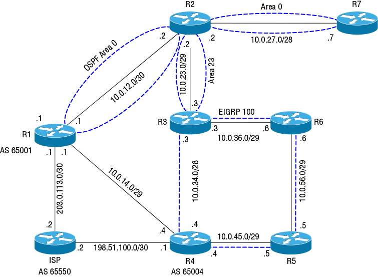
Type 4—Autonomous System Boundary Router (ASBR) Summary LSA and Type 5—AS External LSA
Neighbor Operations
Configuring OSPF
Configuring Area 0 on a Broadcast Network
R1#debug ip ospf hello
OSPF hello debugging is on
R1#conf t
Enter configuration commands, one per line. End with CNTL/Z.R1(config)#router ospf 1R1(config-router)#router-id 1.1.1.1R1(config-router)#network 10.0.12.1 0.0.0.0 area 0
R1(config-router)#
! OSPF begins sending Hellos out looking for another router to form an adjacency ! with.
OSPF-1 HELLO Gi0/0: Send hello to 224.0.0.5 area 0 from 10.0.12.1R2#debug ip ospf hello
OSPF hello debugging is on
R2#conf t
Enter configuration commands, one per line. End with CNTL/Z.
R2(config)#router ospf 1
R2(config-router)#router-id 2.2.2.2
R2(config-router)#network 10.0.12.2 0.0.0.0 area 0
R2(config-router)#
OSPF-1 HELLO Gi0/0: Send hello to 224.0.0.5 area 0 from 10.0.12.2
! R2 receives a Hello from R1 and responds
OSPF-1 HELLO Gi0/0: Rcv hello from 1.1.1.1 area 0 10.0.12.1
OSPF-1 HELLO Gi0/0: Send immediate hello to nbr 1.1.1.1, src address 10.0.12.1
OSPF-1 HELLO Gi0/0: Send hello to 10.0.12.1 area 0 from 10.0.12.2
R2(config-router)#
! R1 and R2 exchange LSAs and form a full adjacency
%OSPF-5-ADJCHG: Process 1, Nbr 1.1.1.1 on GigabitEthernet0/0 from LOADING to FULL, Loading DoneViewing Neighbor Adjacencies
R2#show ip ospf neighbor
! R1 and R2 have a full adjacency, and R2 is the DR
Neighbor ID     Pri   State           Dead Time   Address         Interface
1.1.1.1 1 FULL/BDR 00:00:35 10.0.12.1 GigabitEthernet0/0Rigging the Designated Router Election
R2#conf t
Enter configuration commands, one per line.  End with CNTL/Z.
R2(config)#int gi0/0
R2(config-if)#ip ospf priority 255R2#show ip ospf interface gigabitEthernet 0/0
GigabitEthernet0/0 is up, line protocol is up
Internet Address 10.0.12.2/30, Area 0, Attached via Network Statement
Process ID 1, Router ID 2.2.2.2, Network Type BROADCAST, Cost: 1
Topology-MTID Cost Disabled Shutdown Topology Name
0 1 no no Base
Transmit Delay is 1 sec, State DR, Priority 255
! Output truncatedR1#conf t
Enter configuration commands, one per line. End with CNTL/Z.
R1(config)#int gi0/0
R1(config-if)#ip ospf priority 0![]() If you set the priority of a DR or BDR to 0, it will immediately relinquish its role, triggering a new election.
If you set the priority of a DR or BDR to 0, it will immediately relinquish its role, triggering a new election.R2#clear ip ospf process
Reset ALL OSPF processes? [no]: y
R2#
%OSPF-5-ADJCHG: Process 1, Nbr 1.1.1.1 on GigabitEthernet0/0 from FULL to DOWN, Neighbor Down: Interface down or detached
R2#show ip ospf interface gi0/0
GigabitEthernet0/0 is up, line protocol is up
Internet Address 10.0.12.2/30, Area 0, Attached via Network Statement
Process ID 1, Router ID 2.2.2.2, Network Type BROADCAST, Cost: 1
Topology-MTID Cost Disabled Shutdown Topology Name
0 1 no no Base
Transmit Delay is 1 sec, State WAITING, Priority 255%OSPF-5-ADJCHG: Process 1, Nbr 1.1.1.1 on GigabitEthernet0/0 from LOADING to FULL, Loading DoneR2#show ip ospf interface
GigabitEthernet0/0 is up, line protocol is up
Internet Address 10.0.12.2/30, Area 0, Attached via Network Statement
Process ID 1, Router ID 2.2.2.2, Network Type BROADCAST, Cost: 1
Topology-MTID Cost Disabled Shutdown Topology Name
0 1 no no Base
Transmit Delay is 1 sec, State DR, Priority 255
Designated Router (ID) 2.2.2.2, Interface address 10.0.12.2
No backup designated router on this network
! Output truncatedR2#show ip ospf neighbor
Neighbor ID Pri State Dead Time Address Interface
! R1 has a priority of 0 and is neither a DR nor a BDR
1.1.1.1 0 FULL/DROTHER 00:00:31 10.0.12.1 GigabitEthernet0/0
3.3.3.3 0 FULL/ - 00:00:39 10.0.23.3 GigabitEthernet0/1Viewing and Understanding LSAs
R2#show ip ospf database

            OSPF Router with ID (2.2.2.2) (Process ID 1)
! Type 1 Router LSAs for Area 0 are listed first.

               Router Link States (Area 0)

Link ID         ADV Router      Age         Seq#       Checksum Link count
1.1.1.1         1.1.1.1         381         0x80000006 0x007581 1
2.2.2.2         2.2.2.2         304         0x80000006 0x003AB2 1
! Next we have Type 2 Network LSAs for Area 0. These are generated by the DR (R2) and
! describe the IP subnet for the segment (in this case, the link between R1 and R2).

               Net Link States (Area 0)

Link ID         ADV Router      Age         Seq#       Checksum
10.0.12.2       2.2.2.2         304         0x80000005 0x00A468
! Here we have Type 3 Summary LSAs advertised into Area 0. The 10.0.23.0 subnet is in
! Area 23, and R2 is the ABR, so it generates this LSA and advertises it into Area 0
! to tell routers in Area 0 how to reach the subnet.

               Summary Net Link States (Area 0)

Link ID         ADV Router      Age         Seq#       Checksum
10.0.23.0       2.2.2.2         304         0x80000005 0x00A471

! Remember that Type 1 Router LSAs never leave an area, so these LSAs in Area 23 are
! different than the ones in Area 0.

               Router Link States (Area 23)

Link ID         ADV Router      Age         Seq#       Checksum Link count
2.2.2.2         2.2.2.2         304         0x80000006 0x00D4EE 2
3.3.3.3         3.3.3.3         317         0x80000031 0x001B79 2

! R2 generates a complementary Type 3 Summary LSA for Area 23, telling those routers
! how to reach the 10.0.12.0 subnet in Area 0.

               Summary Net Link States (Area 23)

Link ID         ADV Router      Age         Seq#       Checksum
10.0.12.0       2.2.2.2         304         0x8000002E 0x00E310
Viewing Type 1 Router LSAs
R2#show ip ospf database router

            OSPF Router with ID (2.2.2.2) (Process ID 1)

               Router Link States (Area 0)

  LS age: 493
  Options: (No TOS-capability, DC)
  LS Type: Router Links
! The Link state ID uniquely describes the Router LSA, and it's always identified by
! the router RID. This is a good reason to deliberately configure the RID to be
! something that helps you easily identify the router.

  Link State ID: 1.1.1.1
! The following LSA was generated by R1

  Advertising Router: 1.1.1.1
  LS Seq Number: 80000002
  Checksum: 0x7D7D
  Length: 36
! As expected, R1 has only one configured link (to R2).

  Number of Links: 1
! This LSA describes this link as connected to a transit network, OSPF parlance for a
! multi-access network. Notice that it has no IP subnet information, but it does
! reference the interface address (10.0.12.1). The subnet information is contained in
! a separate Network LSA that we'll look at in a moment.

    Link connected to: a Transit Network
! Notice that this LSA lists the DR for the segment, which is R2.

     (Link ID) Designated Router address: 10.0.12.2
     (Link Data) Router Interface address: 10.0.12.1
      Number of MTID metrics: 0
       TOS 0 Metrics: 1

! The second Router LSA describing R2 begins here.

  LS age: 492
  Options: (No TOS-capability, DC)
  LS Type: Router Links
  Link State ID: 2.2.2.2
! This LSA was generated by R2. It's almost a mirror image of the preceding LSA
! generated by R1.

  Advertising Router: 2.2.2.2
  LS Seq Number: 80000002
  Checksum: 0x42AE
  Length: 36
  Number of Links: 1
    Link connected to: a Transit Network
     (Link ID) Designated Router address: 10.0.12.2
     (Link Data) Router Interface address: 10.0.12.2
      Number of MTID metrics: 0
       TOS 0 Metrics: 1
Viewing Type 2 Network LSAs
R2#show ip ospf database network

            OSPF Router with ID (2.2.2.2) (Process ID 1)

               Net Link States (Area 0)

  LS age: 1762
  Options: (No TOS-capability, DC)
  LS Type: Network Links
! R2 is the DR, so it generates and sends the Network LSA

  Link State ID: 10.0.12.2 (address of Designated Router)
  Advertising Router: 2.2.2.2
  LS Seq Number: 80000029
  Checksum: 0x5C8C
  Length: 32
! The Network LSA describes the subnet (10.0.12.0/30) and the routers attached to it:
! R2 and R1.

  Network Mask: /30
       Attached Router: 2.2.2.2
Attached Router: 1.1.1.1![]() A transit network can't span multiple OSPF areas. All OSPF interfaces connected to the same subnet must be in the same area.
A transit network can't span multiple OSPF areas. All OSPF interfaces connected to the same subnet must be in the same area.Configuring Area 23 on a Point-to-Point Network
R2(config)#interface gi0/1
R2(config-if)#ip ospf network ?
  broadcast            Specify OSPF broadcast multi-access network
  non-broadcast        Specify OSPF NBMA network
  point-to-multipoint  Specify OSPF point-to-multipoint network
  point-to-point       Specify OSPF point-to-point network

R2(config-if)#ip ospf network point-to-point
R2(config-if)#router ospf 1
R2(config-router)#network 10.0.23.2 0.0.0.0 area 23R3(config)#interface gi0/1
R3(config-if)#ip ospf network
R3(config-if)#ip ospf network point-to-point
R3(config-if)#router ospf 1
R3(config-router)#router-id 3.3.3.3
R3(config-router)#network 10.0.23.3 0.0.0.0 area 23
R3(config-router)#
%OSPF-5-ADJCHG: Process 1, Nbr 2.2.2.2 on GigabitEthernet0/1 from LOADING to FULL, Loading Done
R3(config-router)#exit
R3(config)#exit
%SYS-5-CONFIG_I: Configured from console by console
R3#show ip ospf neighbor
! There's no DR because this is a point-to-point link.
Neighbor ID Pri State Dead Time Address Interface
2.2.2.2 0 FULL/ - 00:00:35 10.0.23.2 GigabitEthernet0/1R3#show ip ospf database router
OSPF Router with ID (3.3.3.3) (Process ID 1)
Router Link States (Area 23)
LS age: 40
Options: (No TOS-capability, DC)
LS Type: Router Links
Link State ID: 2.2.2.2
Advertising Router: 2.2.2.2
LS Seq Number: 80000004
Checksum: 0xD8EC
Length: 48
! R2 is an ABR because it's connected to area 0 and area 23.
Area Border Router
Number of Links: 2
! This first LSA describes the link connected to R3.
Link connected to: another Router (point-to-point)
(Link ID) Neighboring Router ID: 3.3.3.3
(Link Data) Router Interface address: 10.0.23.2
Number of MTID metrics: 0
TOS 0 Metrics: 1
! This next LSA describes the 10.0.23.0/29 subnet.
Link connected to: a Stub Network
(Link ID) Network/subnet number: 10.0.23.0
(Link Data) Network Mask: 255.255.255.248
Number of MTID metrics: 0
TOS 0 Metrics: 1
! Following are the Router LSAs generated by R3. Notice that R3 is not listed as
! an ABR because it has interfaces only in Area 23.
LS age: 39
Options: (No TOS-capability, DC)
LS Type: Router Links
Link State ID: 3.3.3.3
Advertising Router: 3.3.3.3
LS Seq Number: 80000002
Checksum: 0x794A
Length: 48
Number of Links: 2
Link connected to: another Router (point-to-point)
(Link ID) Neighboring Router ID: 2.2.2.2
(Link Data) Router Interface address: 10.0.23.3
Number of MTID metrics: 0
TOS 0 Metrics: 1
Link connected to: a Stub Network
(Link ID) Network/subnet number: 10.0.23.0
(Link Data) Network Mask: 255.255.255.248
Number of MTID metrics: 0
TOS 0 Metrics: 1![]() Intriguingly, the subnet masks on point-to-point interfaces don't have to match in order for OSPF neighbors to form an adjacency or exchange routes.
Intriguingly, the subnet masks on point-to-point interfaces don't have to match in order for OSPF neighbors to form an adjacency or exchange routes.Viewing Type 3 Summary LSAs
R2#show ip ospf database summary

            OSPF Router with ID (2.2.2.2) (Process ID 1)
! This Summary LSA is advertised into Area 0 and describes the 10.0.23.0/29 subnet
! in Area 23

               Summary Net Link States (Area 0)

  LS age: 1253
  Options: (No TOS-capability, DC, Upward)
  LS Type: Summary Links(Network)
Link State ID: 10.0.23.0 (summary Network Number)

  Advertising Router: 2.2.2.2
  LS Seq Number: 80000005
  Checksum: 0xA471
  Length: 28
Network Mask: /29

       MTID: 0        Metric: 1

! This one is advertised into Area 23 and describes the 10.0.12.0/30 subnet in area 0.

               Summary Net Link States (Area 23)

  LS age: 1253
  Options: (No TOS-capability, DC, Upward)
  LS Type: Summary Links(Network)
Link State ID: 10.0.12.0 (summary Network Number)

  Advertising Router: 2.2.2.2
  LS Seq Number: 8000002E
  Checksum: 0xE310
  Length: 28
Network Mask: /30

MTID: 0 Metric: 1R3#show ip ospf database summary
OSPF Router with ID (3.3.3.3) (Process ID 1)
Summary Net Link States (Area 23)
LS age: 1130
Options: (No TOS-capability, DC, Upward)
LS Type: Summary Links(Network)
! The IP subnet is 10.0.12.0/30
Link State ID: 10.0.12.0 (summary Network Number)
! R2 advertised this Summary LSA, so it's logically the next hop to reach the
! 10.0.12.0/30 subnet
Advertising Router: 2.2.2.2
LS Seq Number: 80000001
Checksum: 0x3EE2
Length: 28
Network Mask: /30
MTID: 0 Metric: 1R3#show ip route ospf
! Output truncated
Gateway of last resort is not set
10.0.0.0/8 is variably subnetted, 7 subnets, 4 masks
! This is an OSPF inter-area (IA) route. The next hop is R2's interface address.
O IA 10.0.12.0/30 [110/2] via 10.0.23.2, 00:08:28, GigabitEthernet0/1R3#traceroute 10.0.12.1 source 10.0.23.3
Type escape sequence to abort.
Tracing the route to 10.0.12.1
VRF info: (vrf in name/id, vrf out name/id)
1 10.0.23.2 8 msec 4 msec 4 msec ! R2
2 10.0.12.1 9 msec 7 msec 10 msec ! R1R1#show ip ospf database summary
OSPF Router with ID (1.1.1.1) (Process ID 1)
Summary Net Link States (Area 0)
LS age: 1761
Options: (No TOS-capability, DC, Upward)
LS Type: Summary Links(Network)
Link State ID: 10.0.23.0 (summary Network Number)
Advertising Router: 2.2.2.2
LS Seq Number: 80000005
Checksum: 0xA471
Length: 28
Network Mask: /29
MTID: 0 Metric: 1R1#show ip route ospf
! Output truncated
Gateway of last resort is not set
10.0.0.0/8 is variably subnetted, 5 subnets, 3 masks
O IA 10.0.23.0/29 [110/2] via 10.0.12.2, 02:45:05, GigabitEthernet0/0Authentication
Authentication Types
Configuring Interface Authentication
R2(config)#int gi0/2
! We'll assign the key an ID of 1. The key ID must match on both ends.

R2(config-if)#ip ospf message-digest-key 1 md5 secretpassword
! Here are the options for configuring the different authentication types

R2(config-if)#ip ospf authentication ?
  key-chain       Use a key-chain for cryptographic authentication keys
! MD5 authentication. This is the one we want.

  message-digest  Use message-digest authentication
! Null authentication

  null            Use no authentication
! Simply hitting enter without further keywords will give you
! clear text authentication

  <cr>
R2(config-if)#ip ospf authentication message-digest
R2(config-if)#router ospf 1
R2(config-router)#network 10.0.27.2 0.0.0.0 area 0
! Verify that the interface is configured to use authentication

R2(config-router)#do show ip ospf interface gi0/2 | b Crypto
  Cryptographic authentication enabled
Youngest key id is 1R7(config)#int gi0/2
! Configure the same key ID and shared secret
R7(config-if)#ip ospf message-digest-key 1 md5 secretpassword
R7(config-if)#ip ospf authentication message-digest
R7(config-if)#router ospf 1
R7(config-router)#network 10.0.27.7 0.0.0.0 area 0
R7(config-router)#
! Because the keys match, R2 and R7 immediately form a full adjacency
%OSPF-5-ADJCHG: Process 1, Nbr 2.2.2.2 on GigabitEthernet0/2 from LOADING to FULL, Loading Done![]() Don't confuse the ip ospf message-digest-key interface command with the ip ospf authentication-key command. The latter is for clear-text authentication only.
Don't confuse the ip ospf message-digest-key interface command with the ip ospf authentication-key command. The latter is for clear-text authentication only.R7#show ip route ospf
! Output truncated
Gateway of last resort is not set
10.0.0.0/8 is variably subnetted, 4 subnets, 4 masks
! The route to the 10.0.12.0/30 prefix (between R1 and R2) is an inter-area
! route, designated by an "O".
O 10.0.12.0/30 [110/2] via 10.0.27.2, 00:02:43, GigabitEthernet0/2
! The prefix from the 10.0.23.0/29 subnet between R2 and R3 is an inter-area (IA) route.
O IA 10.0.23.0/29 [110/2] via 10.0.27.2, 00:02:43, GigabitEthernet0/2Configuring Area Authentication
! Gi0/0 is the interface facing R2. We'll configure the shared secret
! "oursecret" using MD5

R1(config-router)#int gi0/0
R1(config-if)#ip ospf message-digest-key 1 md5 oursecret
! Enable area 0 authentication using MD5

R1(config-router)#area 0 authentication message-digest
R1(config-router)#
! Because R2's interface facing R1 isn't yet configured for authentication,
! the Dead Timer
! expires and the adjacency drops

%OSPF-5-ADJCHG: Process 1, Nbr 2.2.2.2 on GigabitEthernet0/0 from FULL to DOWN, Neighbor Down: Dead timer expiredR2(config)#int gi0/0
R2(config-if)#ip ospf message-digest-key 1 md5 oursecret
R2(config-if)#router ospf 1
R2(config-router)#area 0 authentication message-digest
R2(config-router)#
%OSPF-5-ADJCHG: Process 1, Nbr 1.1.1.1 on GigabitEthernet0/0 from LOADING to FULL, Loading DoneR2#show ip ospf | s Area
Area BACKBONE(0)
Number of interfaces in this area is 2
! Area 0 has MD5 authentication enabled. Incidentally, the incomplete sentence
! "Area ranges are" is strange looking, but normal.
Area has message digest authentication
Area ranges are
Area 23
Number of interfaces in this area is 1
! Area 23 isn't configured to use authentication
Area has no authentication
Area ranges areR2#show ip ospf interface brief
Interface PID Area IP Address/Mask Cost State Nbrs F/C
Gi0/2 1 0 10.0.27.2/28 1 DR 1/1
Gi0/0 1 0 10.0.12.2/30 1 DR 1/1
Gi0/1 1 23 10.0.23.2/29 1 P2P 1/1Passive Interfaces
R1(config)#router ospf 1
R1(config-router)#passive-interface gi0/1
! Now let's advertise the subnet 10.0.14.0/29 into area 0.

R1(config-router)#network 10.0.14.1 0.0.0.0 area 0
! Verify

R1(config-router)#do show ip ospf int gi0/1
GigabitEthernet0/1 is up, line protocol is up
  Internet Address 10.0.14.1/29, Area 0, Attached via Network Statement
  Process ID 1, Router ID 1.1.1.1, Network Type BROADCAST, Cost: 1
  Topology-MTID    Cost    Disabled    Shutdown      Topology Name
        0           1         no          no            Base
  Transmit Delay is 1 sec, State DR, Priority 1
  Designated Router (ID) 1.1.1.1, Interface address 10.0.14.1
  No backup designated router on this network
  Timer intervals configured, Hello 10, Dead 40, Wait 40, Retransmit 5
    oob-resync timeout 40
! R1 doesn't send Hellos out of this interface because it's passive

No Hellos (Passive interface)R1#show ip ospf database router 1.1.1.1
OSPF Router with ID (1.1.1.1) (Process ID 1)
Router Link States (Area 0)
LS age: 301
Options: (No TOS-capability, DC)
LS Type: Router Links
Link State ID: 1.1.1.1
Advertising Router: 1.1.1.1
LS Seq Number: 80000021
Checksum: 0x5960
Length: 48
Number of Links: 2
Link connected to: a Stub Network
(Link ID) Network/subnet number: 10.0.14.0
(Link Data) Network Mask: 255.255.255.248
Number of MTID metrics: 0
TOS 0 Metrics: 1
! Output truncatedR2#show ip route 10.0.14.0
Routing entry for 10.0.14.0/29
Known via "ospf 1", distance 110, metric 2, type intra area
Last update from 10.0.12.1 on GigabitEthernet0/0, 00:08:44 ago
Routing Descriptor Blocks:
* 10.0.12.1, from 1.1.1.1, 00:08:44 ago, via GigabitEthernet0/0
Route metric is 2, traffic share count is 1Injecting a Default Route
R1(config)#ip route 0.0.0.0 0.0.0.0 203.0.113.2
R1(config)#do show ip route static
! Output truncated

S*    0.0.0.0/0 [1/0]
via 203.0.113.2R1(config-router)#default-information originateR1#show ip ospf database external
OSPF Router with ID (1.1.1.1) (Process ID 1)
Type-5 AS External Link States
LS age: 139
Options: (No TOS-capability, DC, Upward)
LS Type: AS External Link
Link State ID: 0.0.0.0 (External Network Number )
Advertising Router: 1.1.1.1
LS Seq Number: 80000001
Checksum: 0x1D91
Length: 36
Network Mask: /0
Metric Type: 2 (Larger than any link state path)
MTID: 0
Metric: 1
Forward Address: 0.0.0.0
External Route Tag: 1R3#show ip route ospf
! Output truncated
! The default route is an external (E2) route, indicating that it was learned from a
! type 5 External LSA
O*E2 0.0.0.0/0 [110/1] via 10.0.23.2, 00:02:49, GigabitEthernet0/1
10.0.0.0/8 is variably subnetted, 9 subnets, 4 masks
O IA 10.0.12.0/30 [110/2] via 10.0.23.2, 02:34:19, GigabitEthernet0/1
O IA 10.0.14.0/29 [110/3] via 10.0.23.2, 00:20:37, GigabitEthernet0/1
O IA 10.0.27.0/28 [110/2] via 10.0.23.2, 03:37:51, GigabitEthernet0/1Inter-Area Summarization
R2#show ip ospf database
! Output truncated
               Summary Net Link States (Area 23)

Link ID         ADV Router      Age         Seq#       Checksum
10.0.12.0       2.2.2.2         1998        0x8000000D 0x0026EE
10.0.14.0       2.2.2.2         1998        0x80000004 0x00140B
10.0.27.0 2.2.2.2 1998 0x8000000A 0x003ED6R2#conf t
R2(config)#router ospf 1
R2(config-router)#area 0 range 10.0.0.0 255.255.224.0R2#show ip ospf database
! Output truncated
Summary Net Link States (Area 23)
Link ID ADV Router Age Seq# Checksum
10.0.0.0 2.2.2.2 15 0x80000001 0x003910R3#show ip route ospf
! Output truncated
O*E2 0.0.0.0/0 [110/1] via 10.0.23.2, 01:46:58, GigabitEthernet0/1
10.0.0.0/8 is variably subnetted, 7 subnets, 4 masks
O IA 10.0.0.0/19 [110/2] via 10.0.23.2, 00:01:18, GigabitEthernet0/1Route Filtering
R2(config-router)#area 0 range 10.0.0.0 255.255.224.0 not-advertiseR3#show ip ospf database summary
OSPF Router with ID (3.3.3.3) (Process ID 1)R3#show ip route ospf
! Output truncated
O*E2 0.0.0.0/0 [110/1] via 10.0.23.2, 02:22:35, GigabitEthernet0/1! Create the prefix list to deny only the 10.0.23.0/29 prefix, while allowing
! all others.
R2(config)#ip prefix-list no-23 deny 10.0.23.0/29
R2(config)#ip prefix-list no-23 permit 0.0.0.0/0 le 32
R2(config)#router ospf 1
! Any prefixes that match the no-23 prefix list will not be advertised into area 0
R2(config-router)#area 0 filter-list prefix no-23 inR2#show ip ospf database summary
OSPF Router with ID (2.2.2.2) (Process ID 1)Distribute Lists
! Create a prefix list to match only the default route

R3(config)#ip prefix-list nodefault deny 0.0.0.0/0
R3(config)#ip prefix-list nodefault permit 0.0.0.0/0 le 32
R3(config)#router ospf 1
! R3 will refuse to install in its routing table any prefix denied by the
! nodefault prefix list

R3(config-router)#distribute-list prefix nodefault in
R3(config-router)#do show ip route 0.0.0.0
% Network not in tableR3(config-router)#do show ip ospf database external
OSPF Router with ID (3.3.3.3) (Process ID 1)
Type-5 AS External Link States
LS age: 1916
Options: (No TOS-capability, DC, Upward)
LS Type: AS External Link
Link State ID: 0.0.0.0 (External Network Number )
Advertising Router: 1.1.1.1
LS Seq Number: 80000005
Checksum: 0x1595
Length: 36
Network Mask: /0
Metric Type: 2 (Larger than any link state path)
MTID: 0
Metric: 1
Forward Address: 0.0.0.0
External Route Tag: 1Summary
Exam Essentials
Exercises

Review Questions