
Chapter 5. Dynamic Multipoint Virtual Private Network (DMVPN)
This chapter covers the following subjects:
• DMVPN Overview: This section provides an overview of the advantages DMVPN provides and compares DMVPN to the legacy site-to-site crypto map solution.
• Network Components: This section examines the components of DMPVN and how they work together to create a dynamic solution.
• DMVPN Design Considerations: This section discusses design issues that must be considered before deploying a DMVPN solution as well as the differences between DMVPN Phase 2 and DMVPN phase 3 configuration.
• DMVPN Hub-and-Spoke Implementation (IPv4 and IPv6): This section steps through a basic DMVPN hub-and-spoke (IPv4/IPv6) configuration. Examples demonstrate how the DMVPN components interact to provide a comprehensive three-router solution.
• DMVPN Troubleshooting: This section discusses how to troubleshoot DMVPN components and provides potential solutions.
“If you read someone else’s diary, you get what you deserve.”
—David Sedaris
This chapter covers the following exam objectives:
• 1.0 Site-to-site Virtual Private Networks on Routers and Firewalls
• 1.2 Describe DMVPN
• 3.0 Troubleshooting using ASDM and CLI
• 3.1 Troubleshoot IPsec
• 3.2 Troubleshoot DMVPN
• 4.0 Secure Communications Architectures
• 4.1 Describe functional components of GETVPN, FlexVPN, DMVPN, and IPsec for site-to-site VPN solutions
• 4.3 Recognize VPN technology based on configuration output for site-to-site VPN solutions
• 4.6 Design site-to-site VPN solutions
In earlier chapters of this book, you have seen that secure VPN technology varies and has been adapted to be used in many different architectures by vastly different organizations. This chapter explores a dynamic adaptation of the site-to-site VPN solution. Traditional site-to-site VPNs did not scale easily, and Dynamic Multipoint Virtual Private Network (DMVPN) was designed to dynamically establish connections with minimal administrative overhead. Furthermore, traditional site-to-site VPNs had various challenges in supporting dynamic routing protocols, voice over IP (VoIP), and streaming video. All of these technologies are needed to support large-scale telecommuter and remote branch networks. In addition, the dynamic nature of DMVPN enables optimization of network paths, which in turn reduces latency and jitter, which are detrimental to VoIP and video. Organizations are finding that dedicated WAN circuits are no longer necessary for remote connectivity. In its place, organizations are using the Internet and secure communication through VPN technology to achieve the same benefits at a fraction of the cost.
A short summary of the value of DMVPN is that it can lower capital and operation expenses, simplify branch communications, reduce deployment complexity, and improve business resiliency. This is why DMVPN is a widely used VPN option and one you will need to master before attempting the SVPN exam. The SVPN exam expects you to be able to describe the components within a DMVPN deployment, recognize DMVPN configuration components, and troubleshoot a DMVPN deployment.
Note
On the exam, you might see a configuration that includes a misconfigured or broken DMVPN solution. In such a situation, you will need to be able to determine what is wrong, and you will need to know the proper commands to fix the configuration. One of the best ways to learn and prepare for the exam is by getting hands-on experience. Reading this book and working with three routers to try out the examples shown in this chapter is a good way to prepare for the exam.
Learning beyond the SVPN concepts:
• DMVPN Overview
• DMVPN Foundational Concepts
• DMVPN Design Considerations
“Do I Know This Already?” Quiz
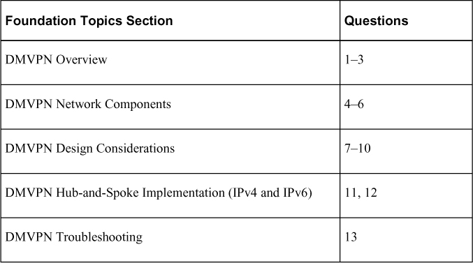
The “Do I Know This Already?” quiz enables you to assess whether you should read the entire chapter. If you miss no more than one of these self-assessment questions, you might want to move ahead to the “Exam Preparation Tasks” section of the chapter. Table 5-1 lists the major headings in this chapter and the “Do I Know This Already?” quiz questions related to the material in each of those sections to help you assess your knowledge of these specific areas. The answers to the “Do I Know This Already?” quiz appear in Appendix A, “Answers to the ‘Do I Know This Already?’ Quizzes.”
Table 5-1 “Do I Know This Already?” Foundation Topics Section-to-Question Mapping
1. What are some of the benefits of DMVPN technology compared to legacy site-to-site VPN solutions? (Choose three.)
a. Multicast support
b. Crypto map enhancement
c. QoS support
d. Dynamic routing protocol capabilities
e. Complex administrative overhead
2. What is the primary reason companies select DMVPN over a legacy crypto map VPN solution?
a. Static Internet addresses
b. Dynamic Internet addresses
c. Complex configuration overhead
d. GRE support
3. What advantages does DMVPN offer that a crypto map–based VPN does not? (Choose two.)
a. Scalability
b. Lack of routing protocol support
c. Reduced configuration overhead
d. Increased bandwidth requirements
4. What are the key components of DMVPN? (Choose all that apply.)
a. mGRE
b. OSPF
c. NHRP
d. Static routes
e. IPsec
f. Routing protocols
5. Which DMVPN component is responsible for mapping the tunnel IP address to an external IP address?
a. OSPF
b. NHRP
c. ISAKMP
d. mGRE
6. Which DMPVN component enables the use of dynamic routing protocols across an IPsec tunnel?
a. OSPF
b. NHRP
c. IPsec
d. GRE
7. Which of the routing protocols used with DMVPN face a split-horizon issue? (Choose two.)
a. OSPF
b. EIGRP
c. BGP
d. RIP
8. Which routing protocol for use with DMVPN faces a non-broadcast multiple-access (NBMA) challenge that must be addressed?
a. OSPF
b. EIGRP
c. BGP
d. RIP
9. Which design considerations must you consider for DMVPN? (Choose two.)
a. The number of IP address ranges
b. The number of remote sites
c. External IP addresses
d. The need for quality of service (QoS) in applications
10. What is the difference between DMVPN Phase 2 and DMVPN Phase 3?
a. There is no difference; they both support only hub-and-spoke solutions.
b. DMVPN Phase 2 supports hub-and-spoke solutions, and DMVPN Phase 3 also supports spoke-to-spoke.
c. DMVPN Phase 2 has smaller routing tables.
d. DMVPN Phase 3 has smaller routing tables.
11. What key word on a hub router enables connections from any remote spokes?
a. multicast
b. dynamic
c. host
d. map
12. Which command for EIGRP prevents a hub router from setting the router advertisement out to a spoke to its own IP address?
a. no ip split-horizon eigrp 1
b. ip eigrp 1 non-broadcast
c. no ip broadcast eigrp 1
d. no ip next-hop-self eigrp 1
13. Which command would show whether the spoke router is registered with the NHS?
a. show ip nhrp detail
b. show ip nhs detail
c. show ip nhrp nhs detail
d. show ip nhrp client
Foundation Topics
Dynamic Multipoint Virtual Private Network (DMVPN) enables different branch locations to communicate in a direct and secure manner using either a public or a private network. DMVPN accomplishes this by utilizing a centralized architecture to ease implementation and management. This enables branch locations to communicate directly with one another, such as when using voice or video between offices, while also not requiring a permanent VPN tunnel between offices.
DMVPN creates a mesh VPN network that is applied selectively based on the connections being utilized by the organization. Each different location, or “spoke,” can connect to any another location in a secure manner. The components involved include GRE tunnel interfaces, IPsec tunnel endpoint discovery, routing protocols for dynamically building the network, and NHRP for locating spokes. We dive into all these topics in this chapter, including supporting both IPv4 and IPv6 as well as troubleshooting your deployment.
The following highlight some of the key benefits of using DMVPN compared to a traditional MPLS network.
• It has the potential for high-performance Internet speed and reliable performance.
• It reduces the cost of secure communications and connections between branch locations by integrating VPN with communication technology (voice and video).
• The centralized system simplifies branch-to-branch connections.
• It reduces the risk of downtime by securing routing with IPsec technology.
DMVPN Overview
Many companies use DMVPN for their wide area network connectivity for one primary reason: It enables remote sites to have dynamic Internet addressing and yet still cryptographically access corporate data. In legacy VPN solutions, companies had to order static IP addresses at each remote site, thereby incurring an extra charge from the ISP and adding to the overall cost of the solution. Furthermore, as you added remote sites to such a solution, the hub router configuration grew exponentially. The days of configuring crypto maps, access control lists (ACLs), policies, and generic routing encapsulation (GRE) tunnels for each remote site have been replaced by the use of more mature and flexible VPN solutions. DMVPN specifically resolved the issues of static routing and cumbersome configuration with the use of an IPsec profile. In the legacy VPN configurations shown in Chapter 3, “Site-to-Site VPNs,” you had to configure one crypto map with multiple policies, each with its own ACL, to indicate which traffic was permitted to go to which destination through the tunnel and what transform set was configured. Each time you added another site-to-site VPN, you added to the policy and, potentially, to the non-NAT ACL.
Legacy Crypto Map VPN Solutions
Figure 5-1 shows an example of a legacy crypto map VPN tunnel solution. This solution requires specific configuration for each site; DMVPN does not require this much configuration. In addition, the legacy solution does not support spoke-to-spoke communication, whereas DMVPN does.

Figure 5-1 Legacy VPN Tunnels
Modern VPN Needs
As shown in Figure 5-2, companies today are using VPNs for a variety of services. In this diagram you can see a mobile user who may be using a video conferencing software package on a laptop in order to communicate. In addition, you can see a remote office that might have multiple users that all have VoIP phones behind the main router; they might need to be able to use the DMVPN solution for not only data but voice and video conferencing. We could expand this diagram by adding another remote office on the DMVPN network, and users from one office would be able to call users in another office by using VoIP rather than traditional dedicated phone circuits from the local provider.
Figure 5-2 A Telecommuter and a Remote Office with VoIP
DMVPN Risks
Although DMVPN provides secure connectivity, it does not make you immune to attacks. Simply adding remote sites to a corporate network increases your organization’s security risk. For example, if a teleworker’s remote machine is infected with ransomware, it might be possible for that ransomware to find other clients to infect through the network. In a fully meshed DMVPN solution, such an attack could cripple an organization’s capability to run its business (see Figure 5-3). So, as you are building out a VPN security solution, you should consider best practices for restricting, monitoring, and policing VPN traffic. Some examples of best practices would be to establish east–west access control and to monitor using traffic capture or NetFlow. In terms of packet monitoring security, implementing breach detection capabilities such as IPS/IDS technology should be considered essential.
Figure 5-3 Ransomware Infection
DMVPN Core Concepts
The features available in a DMVPN solution are similar to those available with both GETVPN and FlexVPN. However, like those types of VPN architectures, DMVPN has its own components and terminology. For example, you need to know and understand GRE tunnels and Next Hop Resolution Protocol (NHRP), which enable DMVPN to scale up to thousands of remote connections and reduce the need for complex administration.
DMVPN Example
Figure 5-4 shows an example of a DMVPN solution where each spoke can communicate with the hub router. In addition, Spoke1 and Spoke2 establish a VPN tunnel directly between themselves.

Figure 5-4 A Full-Mesh DMVPN Tunnel
A critical piece of this solution is that GRE and NHRP work together to resolve the peer destination IP address. In essence, the NHRP configuration on a spoke router forces a registration process that maps the GRE tunnel IP address to the Internet destination IP address for the spoke on the hub NHRP database. Another critical piece of this solution is multipoint Generic Routing Encapsulation (mGRE). We will look more closely at these two components in the next section.
DMVPN, as its name implies, also supports IPsec. The configuration combinations for IPsec are quite extensive, and this chapter covers only some of the key ones; in other chapters, you will see many other configurations that include IPsec. Let’s look at the components of a DMVPN deployment.
Network Components
As mentioned in the last section of this chapter, DMVPN uses several components to achieve either a hub-and-spoke or a spoke-to-spoke solution: mGRE, NHRP, and IPsec. This section examines these components as well as the routing protocols that DMVPN supports. Make sure you are familiar with each of these components before moving to the next part of this chapter. First, we need to understand mGRE.
mGRE
mGRE enables routers to support multiple GRE tunnels on a single interface. This single interface can receive inbound GRE connections from dynamically addressed remote site locations and simultaneously support dynamic routing protocols, IP Multicast, and non-IP protocols. Both GRE and mGRE have a 24-bit header; in some situations, this header can impact application functionality. (We will examine this later in this chapter.) The advantage of using mGRE is that it enables the DMVPN network to replicate the function of a non-broadcast multiple-access (NBMA) multipoint Frame Relay solution (see Figure 5-5). Such solutions were more common in the past, when companies would purchase a Frame Relay WAN architecture from a telephone company and request that it be configured as multipoint. In Figure 5-5, which provides an example of the components in a DMVPN configuration, you can see that, in addition to a VPN tunnel, there are also GRE tunnels configured between sites.
Figure 5-5 GRE Tunnels
GRE and mGRE Advantages
GRE and mGRE have many advantages both with DMVPN and in other solutions. For example, you can use a GRE tunnel to repair network routing links between OSPF areas that have become disconnected, causing routing updates between them to stop. Because GRE uses the IP protocol 47 and encapsulates the entire original IP payload, it supports nontraditional protocols as well as multicast and the use of routing protocols across a VPN tunnel.
GRE has a few limitations, but they are significant:
• GRE is not a cryptographic protocol, and it does not provide data protection.
• GRE can be CPU intensive, and you need to consider this during design.
• The IP MTU and fragmentation issue mentioned earlier might occur with some applications.
• Vendor GRE solutions are not all alike, and integration can be challenging.
NHRP
NHRP is used as the primary communication system for DMVPN hubs to inform spoke devices about other registered spokes. This is a classic client and server protocol: The server (hub) maintains the database of the spokes (clients) that have successfully registered. During the registration process, each spoke provides the server with its public IP address and the internal IP address of its GRE tunnel. The NHRP hub stores that information in the NHRP database so that other spokes can query the database for that information. Notice in Figure 5-6 that the NHRP registration occurs over the tunnel, and the NHRP packet includes the source address of the device that sent the tunnel, the destination address of the tunnel, and the NBMA address (public) of the destination device.
Figure 5-6 NHRP Registration Process
NHRP Example
Figure 5-6 shows IPsec tunnels, the GRE tunnel, and NHRP configured. It shows that the NHRP database on the NHRP server provides both the tunnel and the external IP address of a spoke router. This information is gathered during the spoke registration process.
Remaining DMVPN Components
IPsec is used to secure traffic going across a tunnel. Depending on the architecture of a DMVPN topology, it is possible for spokes to dynamically establish VPN tunnels with other spokes.
Routing is an often-overlooked piece of a DMVPN solution. However, routing is key because it enables a remote site to reach another remote spoke network that it did not initially have in its routing table prior to registration. Understanding DMVPN routing configuration comes down to understanding the shortfalls of routing protocols such as EIGRP and the split-horizon feature. With OSPF, an engineer would need to address the issue of NBMA with either a multipoint OSPF configuration or set up a broadcast network.
Solution Breakdown
In studying and preparing for the SVPN 300-730 exam, a good approach would be to break down the components of a solution down into sub pieces. When you have mastered all the components, troubleshooting DMVPN will be much easier. Table 5-2 will help you study and focus on the key components of a DMVPN configuration.
Table 5-2 Basic DMVPN Configuration Components

DMVPN Design Considerations
Before you start designing a DMVPN network, it is critical to establish a goal for the solution. Just like with any VPN technology, you first need to understand what business problems you are going to solve. Once you have determined the goal, you can work back from the goal to the solution. We performed a similar exercise in the last chapter when covering design considerations for deploying GETVPN.
This section looks at some of the common design challenges and issues that security engineers must consider. In addition, equipment has a significant impact on a solution, and you might need to upgrade some of your equipment to support DMVPN, especially if you are trying to reuse existing equipment for remote site deployments. (Chapter 3 includes a list of pre-design questions that a team should consider before deploying DMVPN. Many of them specifically address equipment issues.)
DMVPN Planning
During the DMVPN design phase, a key constraint would be what applications will be running over the DMVPN links. Are you deploying VoIP or video conferencing solutions? Such low-latency applications might require QoS and priority over other applications. In addition, what level of fault tolerance is needed at the headend (hub) site to which the DMVPN remote sites connect? Will multicast traffic need to traverse the VPN links? What type of routing protocol will you use? The routing protocol setup requires some serious consideration. You should think about the following questions before configuring your routing protocol:
• What network IP blocks need to be accessible from the remote sites?
• Do remote site IP blocks need to be accessible from other locations?
• Does traffic need to be filtered for specific IP address ranges?
• Is QoS required?
Based on the answers to these questions, you might need to configure spoke-to-spoke communication across the VPN tunnel. If the objective of your design is to create spoke-to-spoke communication, you will need to answer another question: Will that traffic go through the headend router, or will it travel directly to the spoke? The answer impacts the configuration of your solution.
You need to think about all the questions posed so far, but these are just a few of the many considerations. Later in this chapter, you will see how to configure traffic from one spoke destined for another to be routed through the hub. You will also see how to configure a solution in which the spoke router can establish a direct VPN link to the other spoke router, thus reducing the overhead on the headend router.
Note
Cisco has a DMVPN Design and Implementation guide available at https://www.cisco.com/c/dam/en/us/products/collateral/security/dynamic-multipoint-vpn-dmvpn/dmvpn_design_guide.pdf?dtid=osscdc000283. We highly recommend that you review it before you deploy DMVPN.
DMVPN Fault Tolerance Considerations
We would be remiss if we did not talk about fault tolerance in this or any section that involves design considerations. Even though we do not focus on fault tolerance/high availability in our examples in this chapter, having multiple hub sites should be part of your design for high-availability purposes. Including multiple hub sites will add to the configuration on the spoke routers, but that additional work will not be a significant amount, and it could also increase the bandwidth at the hub site. The level of fault tolerance your organization requires will impact your solution and its cost. As stated in the last chapter, we find cost is the number of factor that impacts how an organization will include fault tolerance within its VPN design.
Key DMVPN Considerations
One best practice we will continue to use in this chapter is creating a design on paper first. We recommend you share your design with your peers to validate and assess the design before moving forward with any deployment. The following are some of the many factors that should be documented and discussed before an implementation. You find this list to be similar to the one used in the last chapter.
• IOS requirements
• Platform capabilities (and upgrade options)
• IP address scheme: IPv4, IPv6, or both
• Tunnel addresses
• External (public) addresses
• DMVPN hub-and-spoke or partial mesh
• Routing requirements
• Authentication method: RSA signature, PKI, or pre-shared key
• Encryption scheme
• Deployment strategy
• Application requirements
DMVPN Phases
DMVPN comes in three different designs, referred to as DMVPN phase 1, DMVPN phase 2, and DMVPN phase 3. The DMVPN phase you choose determines how spokes communicate with one another as well as the routing configuration. In the next three sections we discuss the differences between each phase and the major configuration differences between them.
DMVPN Phase 1
DMVPN is the first phase that was defined when this technology was implemented by Cisco and is strictly designed for hub-and-spoke communications only. Spoke-to-spoke traffic flows will need to reach the hub and then be transported down to the spoke. This is the exact same traffic flow as a hub-and-spoke design in Frame Relay or ATM. For example, consider the topology shown in Figure 5-7.
Figure 5-7 Basic DMVPN Hub and Spoke Example
R1 is acting as the DMVPN hub for this network and is therefore the NHS for NHRP registration of the spokes. In DMVPN phase 1 the GRE tunnels shown are multipoint GRE on the hub and point-to-point on the spokes. This forces hub-and-spoke traffic flows on the spokes. In addition to this, the next-hop value of any routes sent between spokes and hubs should be changed to reflect the topology. Therefore, the same routing issues with frame-relay and ATM apply to DMVPN (Split Horizon, for example). As a high-level configuration on R1 we can see the basic configurations for DMVPN phase 1.
DMVPN Phase 2
In DMVPN phase 2, spoke-to-spoke traffic flow is now permitted, and all spoke routers implement multipoint GRE. Equally, resolution request NHRP messages are now sent to resolve a spoke's VPN address to its NBMA address. However, this function relies heavily on your routing design and in ensuring that the next-hop address is preserved during advertisement from the hub down to other spokes, much like how the next hop is preserved on an ethernet switch to allow more efficient traffic flows. To demonstrate this, the topology in Figure 5-8 has been updated to reflect this change.
Figure 5-8 Spoke-to-Spoke Added
In DMVPN phase 2, when a spoke router wants to communicate with another spoke router it will look at its routing table to determine the next-hop address.
Spokes preserve their next hop address; because the routing table and NHRP tables are unable to exchange information, each spoke has to hold the full network routing table for all spokes on the DMVPN network. In Figure 5-8, if Spoke1 had a change in its routing table with the failed link that triggered an update, Spoke2 would see this change and update its routing table. The reason is that the Spoke2 routing table has received routes from Spoke1 via the hub router, including the next hop of the tunnel address, which is 192.168.1.2 (Spoke1). Spoke1 only knows of Spoke2 through the tunnel address 192.168.1.3; it is not aware of the NBMA address (public) that lies in between. The hub router knows of the Spoke2 NBMA address and would forward the route update to Spoke2. You need to understand that changes or queries by any spoke of another spoke would, at a minimum, generate an NHRP resolution request to the hub. In this example, a failed link would generate not only an NHRP resolution request but also a routing protocol update packet.
Figure 5-9 shows that a link on Spoke1 has failed. This figure demonstrates that in a DMVPN phase 2 solution, a failed link such as the one on Spoke1 will trigger a routing update being sent to Spoke2 to notify that router of the change.
Figure 5-9 DMVPN Phase 2
DMVPN Phase 3
With DMVPN phase 3, Cisco modified the Cisco Express Forwarding (CEF) table and the NHRP table so that they can work together. This enables the NHRP table to resolve the next hop information and the CEF table to route the packets. This change enables the hub router to set the next hop to itself and advertise summarized routes to all of the spokes. This configuration option supports the use of smaller spoke routers by eliminating the need to support the entire corporate routing table.
Now that we have tackled all the design concepts behind DMVPN, we next learn what is involved with deploying DMVPN. Let’s first start with a look at a hub-and-spoke implementation.
DMVPN Phase 1 Hub-and-Spoke Implementation
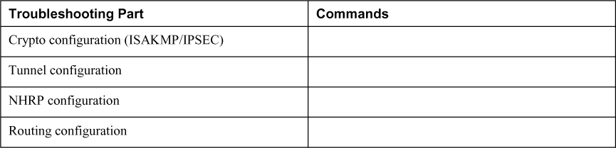
Now it is time to dive into DMVPN implementations. The best way to address learning how technology is configured is to break it down into manageable parts. This section shows the implementation of a basic hub-and-spoke DMVPN design for both IPv4 and IPv6 by breaking down the process into four parts. We highly recommend that you understand how each part works as you study DMVPN technology because you will see questions about the different parts of a DMVPN configuration on the SVPN exam. The following are the four parts of a DMVPN configuration:
• Crypto IPsec policy configuration
• GRE tunnel configuration
• NHRP hub-and-spoke configuration
• Routing configuration
Breaking down the process into these four parts will make it easier to troubleshoot which part of the configuration is incorrect and which parts are correct. It will also help with identifying wrong answers for questions about specific parts of a DMVPN configuration. For example, if you are dealing with a routing issue, any answer regarding the GRE tunnel configuration could be eliminated.
Figure 5-10 shows the topology and IPv4 design, and Figure 5-11 shows the topology and IPv6 design for the following configuration examples. Use this as a reference for this next section.
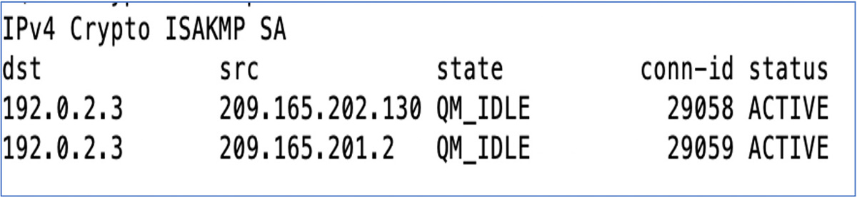
Figure 5-10 DMVPN IPv4 Solution
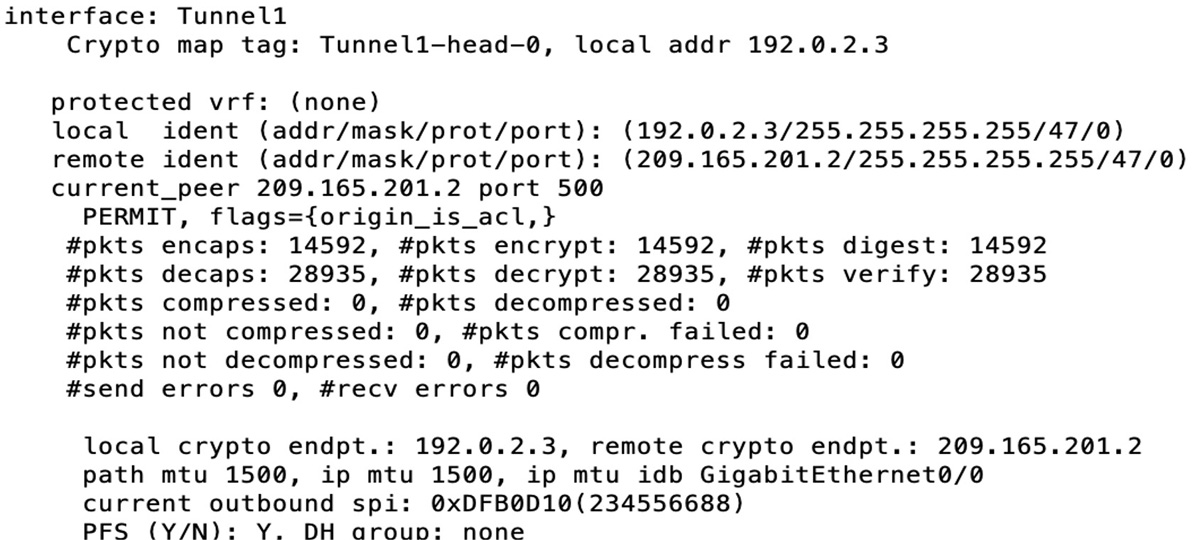
Figure 5-11 DMVPN IPv6 Solution
Crypto IPsec Policy Configuration
As discussed in earlier chapters, the Internet Key Exchange (IKE) management protocol is primarily used to authenticate IPsec peers. Configuring a crypto IPsec policy can be broken into the following three steps:
• Creating an IKE Policy
• Creating Pre-shared Key Authentication Credentials
• Creating a Profile and Transform Set
This section works through each of these three steps starting with creating an IKE Policy.
Creating an IKE Policy
In Example 5-1, it is used by the two spoke routers and the hub router to authenticate, negotiate, and distribute IPsec encryption keys. Today, this is optional on some Cisco platforms as there is a default IKE policy; however, your organization my require a more secure policy. In this example, this policy will be repeated on the two remote site routers (spokes) and must match the HQ router policy. Let’s work through each step of the crypto IPsec policy configuration. We will break this into steps as well to clearly work through how the configuration is performed.
Example 5-1 shows the basic crypto ISAKMP IKE policy used by all the routers in Figures 5-8 and 5-9.
Example 5-1 Creating an IKE Policy
HQ-Router(config)# crypto isakmp policy 10
HQ-Router(config-isakmp)# encryption aes 192
HQ-Router(config-isakmp)# hash sha256
HQ-Router(config-isakmp)# authentication pre-share
HQ-Router(config-isakmp)# group 5
The policy shown in Example 5-1 is policy number 10. You can have policies from 1 to 65535, ordered by priority. If you establish a VPN with another router that does not have a policy matching this one, your router could potentially find another policy that might match that remote side. If, during troubleshooting, you notice that the IKE policy fails to negotiate, the first place to look is at the IKE policy parameters on both routers.
Example 5-1 shows the use of AES-192 encryption and the hash policy SHA-256. Notice in this example that the authentication in use is pre-shared. This means that you are going to have to manually set up authentication keys on all the DMVPN routers. Another option would be to use certificate authority (CA) signatures. The third method for authentication would be to use encrypted nonces. (Both forms of certificate authentication are discussed in Chapter 3.) We recommend that you take the time to learn how to use certificates for authentication because this process is critical for large-scale deployments. By using certificates, you remove the need to keep track of pre-shared keys, and that is a security improvement.
Finally, Example 5-1 specifies group 5 for the Diffie-Hellman key algorithm, which uses a 1536-bit modulus, which in turn uses 2048 bits to create a prime and generate numbers as security association (SA) keys. Depending on your router and its IOS version, you might be able to create a more secure solution by increasing the AES encryption to AES-256 with SHA-512. Chapter 8, “Remote Access VPNs,” covers encryption in more detail.
Creating Pre-shared Key Authentication Credentials
The next step is creating a pre-shared key. Example 5-2 shows an implementation of IPv4 pre-shared keys for the two remote spoke routers.
Example 5-2 Creating Pre-shared Key Authentication Credentials, IPv4
HQ-Router(config)# crypto isakmp key TESTKEY address 209.165.201.2
HQ-Router(config)# crypto isakmp key TESTKEY address 209.165.202.130
On the main router, you need to reference the remote site routers or, in this case, the spokes. It is critical that you reference the public IP address of the router or the address that is reachable by the router if you are implementing a DMVPN solution on a private network. The spoke routers at first have just one crypto pre-shared key configuration line. With spoke-to-spoke configuration, this changes, as you’ll see later in this chapter.
Example 5-3 shows an implementation of IPv6 pre-shared keys for the two remote spoke routers.
Example 5-3 Creating Pre-shared Key Authentication Credentials, IPv6
HQ-Router(config)# crypto isakmp key TESTKEY address ipv6 2001:db8:bbbb:2::2/64
HQ-Router(config)# crypto isakmp key TESTKEY address ipv6 2001:db8:cccc:2::2/64
Notice in Example 5-3 that the IPv6 command has similar syntax to the IPv4 command, and both reference the public endpoint IP addresses of the devices that are authenticating.
Example 5-4 shows the IPv4 pre-shared key used by the spoke to authenticate to the hub router.
Example 5-4 Spoke Router Pre-shared Key in IPv4
Spoke1(config)# crypto isakmp key TESTKEY address 192.0.2.3
Similarly, with IPv6, the spoke would reference the public IPv6 address of the hub router. Example 5-5 shows the IPv6 pre-shared key used by the spoke to authenticate to the hub router.
Example 5-5 Spoke Router Pre-shared Key in IPv6
Spoke1(config)# crypto isakmp key TESTKEY address 2001:db8:aaaa:1::1/64
Creating a Profile
Next, you need to create a profile and transform set. Example 5-6 shows the implementation of a profile and transform set, which is the same for IPv4 and IPv6 and the same on both the hub and the spoke.
Example 5-6 Creating a Profile and a Transform Set for IPv4 or IPv6
HQ-Router(config)# crypto ipsec transform-set MYSET esp-aes esp-sha-hmac
HQ-Router(cfg-crypto-trans)# mode tunnel
HQ-Router(cfg-crypto-trans)# crypto ipsec profile MYIPSECPROFILE
HQ-Router(ipsec-profile)# set transform-set MYSET
Notice that these two commands are tied together by the crypto profile referencing the transform set. You will see later how the profile is used by the DMVPN configuration. As discussed in Chapter 3, the transform set is for IKE phase 2 negotiation of the encrypted tunnel. As with the crypto policy, some IOS versions now include a default transform set, as you can see with the command show crypto ipsec profile in Example 5-7. The key pieces of the transform set are the encryption method, the hash type, and whether Perfect Forward Security (PFS) is used. These must all match except for the security association lifetime. The two sides select the SA lifetime with the smallest size and use that for the tunnel.
In Example 5-7, the command show crypto ipsec profile validates your previous profile configuration steps.
Example 5-7 Output Crypto IPsec Profile
HQ-Router(config)# show crypto ipsec profile
IPSEC profile MYIPSECPROFILE
        Security association lifetime: 4608000 kilobytes/3600 seconds
        Responder-Only (Y/N): N
        PFS (Y/N): N
        Mixed-mode : Disabled
        Transform sets={
                MYSET:  { esp-aes esp-sha-hmac  } ,
        }
IPSEC profile default
        Security association lifetime: 4608000 kilobytes/3600 seconds
        Responder-Only (Y/N): N
        PFS (Y/N): N
        Mixed-mode : Disabled
        Transform sets={
                default:  { esp-aes esp-sha-hmac  } ,
        }
Creating a Transform Set
The transform set is a collection of individual IPsec parameters designed to implement the security policy on the traffic that is transmitted across the tunnel. During ISAKMP IPsec security association negotiation, the two routers need to agree on the parameters; if the parameters are not the same, the tunnel setup fails. For example, if one side has transport mode set to AH and the other side only supports ESP, the negotiation will fail.
Example 5-8 shows how to verify the transform set configuration. It is important that both sides of the tunnel solution have a match.
Example 5-8 Verifying the IPsec Transform Set
HQ-Router(config)# show crypto ipsec transform-set
Transform set default: { esp-aes esp-sha-hmac  }
   will negotiate = { Transport,  },

Transform set MYSET: { esp-aes esp-sha-hmac  }
   will negotiate = { Tunnel,  },
In the default configuration, transport mode only protects the upper layer protocols with payload encapsulation mode, and tunnel mode specifies protects the entire IP datagram.
GRE Tunnel Configuration
A GRE tunnel is required for a DMVPN network. If you think about it, the tunnel interface allows the consolidation of numerous remote site point-to-point links into one interface. In some of the legacy Cisco site-to-site configurations, you would have one crypto map on the outside interface with multiple configuration sections for each remote site VPN link. That would cause the router configuration to be extensive and possibly complex to troubleshoot. With the GRE tunnel solution, you have one tunnel interface scaling to support hundreds of remote site locations. The tunnel interface is designated as a multipoint interface, resulting in an NBMA network. Typically, when you configure a GRE tunnel, the source and destination IP addresses are configured so that the tunnel can be established; however, with DMVPN, you do not need this because you use NHRP to solve endpoint address resolution.
Key Points: A GRE tunnel configuration on the hub consists of a single step, which is creating a multipoint GRE tunnel.
Creating a Multipoint GRE Tunnel on the Hub
Example 5-9 shows how to build a basic DMVPN hub router tunnel configuration. The key to this configuration is the tunnel command, which sets the mode to multipoint. This tunnel configuration works for both IPv4 and IPv6.
Example 5-9 Creating a Multipoint GRE Tunnel on a Hub Router for IPv4 or IPv6
HQ-Router(config)# interface tunnel0
HQ-Router(config-if)# ip address 192.168.1.1 255.255.255.0
HQ-Router(config-if)# ipv6 address 2001:db8:aaaa:1::1/64
HQ-Router(config-if)# tunnel source GigabitEthernet1
HQ-Router(config-if)# tunnel mode gre multipoint
HQ-Router(config-if)# tunnel key 12345
Notice that Example 5-9 has both an IPv4 address and an IPv6 address on the tunnel interface. That means you can configure it for either solution, and you can select the one you need for your environment. The tunnel source is the outside interface (that is, the interface of the router in this example).
The command tunnel mode gre multipoint in Example 5-9 makes the GRE tunnel a multipoint GRE (mGRE) tunnel, which allows multiple remote sites to be grouped into a single multipoint interface. The tunnel key command provides a weak form of security, but it could help prevent misconfiguration of a remote site from impacting a large-scale DMVPN environment.
Creating a GRE Tunnel on the Spoke
Unlike the hub, in DMVPN Phase 1 the spoke uses a point-to-point tunnel. To put another way, the command tunnel mode gre multipoint is replaced with the command tunnel destination ip_address, where ip_address is the public IP address of the hub router, as shown in Example 5-10.
Example 5-10 Configuring a Spoke Router for IPv4
Spoke1(config)# interface tunnel0
Spoke1(config-if)# ip address 192.168.1.2 255.255.255.0
Spoke1(config-if)# tunnel source GigabitEthernet0
Spoke1(config-if)# tunnel destination 192.0.2.3
Spoke1(config-if)# tunnel key 12345
With IPv6, there is a very important command that is often overlooked by VPN administrators. That command is to add ipv6 to the tunnel mode command, as shown in Example 5-11. It is possible to use the tunnel mode command without the ipv6 keyword, but without this keyword, your IPv6 configuration will not work. The other commands are similar to the IPv4 commands.
Note
We cannot stress enough the importance of using the ipv6 keyword with the tunnel mode command for IPv6 because it is critical.
Example 5-11 shows the IPv6 configuration of a spoke router tunnel interface.
Example 5-11 Configuring a Spoke Router for IPv6
Spoke1(config)# interface tunnel0
Spoke1(config-if)# ipv6 address 2001:db8:beef:4::2/64
Spoke1(config-if)# tunnel source GigabitEthernet0
Spoke1(config-if)# tunnel destination 2001:db8:aaaa:1::1
Spoke1(config-if)# tunnel key 12345
The tunnel configuration for the spoke router references the outside interface with the tunnel source command. Next, the tunnel is set to GRE mode so it will support both unicast and multicast traffic. It will be important that the tunnel supports the use of multicast communication mechanisms later, when you want to run routing protocols such as OSPF. As mentioned earlier, the tunnel key command provides a weak form of security, preventing misconfiguration of a spoke router from impacting a production DMVPN network.
NHRP Hub-and-Spoke Configuration
The next part of the configuration is the NHRP hub-and-spoke configuration. Configuring NHRP for hub-and-spoke is a three-step process on the hub:
• Configure NHRP
• Configure the tunnel
• Configure tunnel optional parameters
Configure NHRP on the Hub
Let’s start by setting up NHRP using IPv4. Example 5-12 shows the required commands for NHRP on a hub router tunnel interface with IPv4.
Example 5-12 Setting Up NHRP IPv4 Server Parameters on the mGRE Tunnel
HQ-Router(config)# interface tunnel0
HQ-Router(config-if)# ip nhrp authentication KEY123
HQ-Router(config-if)# ip nhrp map multicast dynamic
HQ-Router(config-if)# ip nhrp network-id 1
Example 5-13 shows the required commands for NHRP on a hub router tunnel interface for IPv6. Notice that these two examples are almost the same; the only difference is the addition of ipv6 at the start of the commands in Example 5-13.
Example 5-13 Setting Up NHRP IPv6 Server Parameters on the mGRE Tunnel
HQ-Router(config)# interface tunnel0
HQ-Router(config-if)# ipv6 nhrp authentication KEY123
HQ-Router(config-if)# ipv6 nhrp map multicast dynamic
HQ-Router(config-if)# ipv6 nhrp network-id 1
The tunnel interface is set up as NBMA. You need a mechanism to allow the remote sites to communicate with the hub router. NHRP acts like dynamic DNS, as it allows remote sites to communicate and register with the DMVPN hub router. The command map multicast dynamic in Example 5-12 and Example 5-13 enables the DMVPN hub router to receive inbound registration requests from any spoke router IP address. Furthermore, the dynamic command enables the replication of multicast packets to each of the spoke routers through the single tunnel interface. Think of this in terms of the hub router referencing the NHRP database, and for each entry, it sends a unicast/multicast packet to that spoke IP address. It does this until each spoke has received the routing update. This way, the router is able to establish dynamic routing protocol adjacencies by utilizing the database to map the multicast endpoints.
Configure NHRP on the Spoke
The configuration of NHRP on the spoke router is different from the configuration on the hub router. Notice that there are a few more commands, and you must specify the IP address of the next hop server. In this case, you provide the tunnel IP address for the hub router. In addition, you add an NBMA address that can receive the broadcast or multicast packets you send out the tunnel interface. Finally, the key to mapping the NHRP tunnel address to the outside public address is to provide the mapping of the NHS tunnel IP address (192.168.1.1) to the NBMA IP address (192.0.2.3).
Example 5-14 shows a basic IPv4 NHRP configuration setup.
Example 5-14 Configuring NHRP on a Spoke Router for IPv4
Spoke1(config)# interface tunnel0
Spoke1(config-if)# ip nhrp authentication KEY123
Spoke1(config-if)# ip nhrp network-id 1
Spoke1(config-if)# ip nhrp nhs 192.168.1.1
Spoke1(config-if)# ip nhrp map multicast 192.0.2.3
Spoke1(config-if)# ip nhrp map 192.168.1.1 192.0.2.3
The IPv6 configuration of NHRP on the spoke is different from the configuration on the hub router, just as it is for IPv4. You use a few more commands and must specify the IP address of the NHS. In this case, you provide the tunnel IP address for the hub router (2001:db8:beef:1::1). In addition, you add an NBMA address that can receive the broadcast or multicast packets you send out the tunnel interface. Finally, it is critical to provide the mapping of the NHS tunnel IP address (192.168.1.1) to the NBMA IP address (192.0.2.3).
Example 5-15 shows a basic IPv6 NHRP configuration setup.
Example 5-15 Configuring NHRP on a Spoke Router for IPv6
Spoke1(config)# interface tunnel0
Spoke1(config-if)# ipv6 nhrp authentication KEY123
Spoke1(config-if)# ipv6 nhrp network-id 1
Spoke1(config-if)# ipv6 nhrp nhs 2001:db8:beef:1::1
Spoke1(config-if)# ipv6 nhrp map multicast 2001:db8:aaaa:1::1
Spoke1(config-if)# ipv6 nhrp map 2001:db8:beef:1::1/64 2001:db8:aaaa:1::1
Configure Tunnel Protection
Now we need to configure the tunnel interface. Example 5-16 shows the configuration required to encrypt the traffic passing through the tunnel. This same configuration should be applied to both the hubs and spokes
Example 5-16 Configuring the Tunnel Interface with IPsec Profile Protection
HQ-Router(config)# interface tunnel0
HQ-Router(config-if)# tunnel protection ipsec profile MYIPSECPROFILE
The tunnel protection ipsec profile command applies the IPsec profile created previously to the tunnel interface. No crypto map is required. All traffic that passes through the tunnel will be encrypted with IPsec, and traffic outside the tunnel will not be encrypted. The use of tunnel protection and an IPsec profile significantly simplifies of the IPsec configuration when compared to crypto maps.
Configure Tunnel Optional Parameters
Next, we need to address issues such as MTU size and the maximum segment size that is negotiated during the TCP synchronization handshake. For any TCP packet going through the tunnel, the router will adjust the maximum segment size (MSS) in the TCP header to match the value you have set it to. This will force the end hosts to also adjust their setting to this value. The mtu and adjust-mss commands help resolve issues with most TCP-based applications that need to traverse the DMVPN tunnel.
Example 5-17 shows additional commands to prevent applications from failing to function across the DMVPN tunnel.
Example 5-17 Configuring the mGRE Interface with Optional IP Parameters
HQ-Router(config)# interface tunnel0
HQ-Router(config-if)# ip mtu 1400
HQ-Router(config-if)# ip tcp adjust-mss 1360
IPv6 has a different header than with IPv4. You still have to be concerned about the MTU size, but with IPv6, the fragmentation and reassembly process is improved; thus, most hops can handle average IP datagrams along the path without needing to fragment packets.
IPv6 has built-in solutions to address fragmentation, and Example 5-18 shows that you only need to adjust the MTU size.
Example 5-18 Sample IPv6 Configuration of the mGRE Interface
HQ-Router(config)# interface tunnel0
HQ-Router(config-if)# ipv6 mtu 1400
Routing Protocol Configuration
Routing protocol configuration is the final part in setting up a DMVPN solution. During the design phase, you needed to determine which routing protocol you would select. There are a few options, such as EIGRP or OSPF. This section walks you through an example of configuring EIGRP. (For other configuration examples, such as OSPF, please refer to the documentation links included at the end of this chapter.)
Configure Routing on the Hub
With DMVPN, the NHRP database enables the hub router to replicate the individual multicast packets needed by the routing protocol to each site, one-by-one. In DMVPN, the routing protocol neighbor relationship is only established between the hub and the spoke routers. Thus, the hub is responsible for distributing routes learned from one spoke back out to another spoke. Thus you run into an issue where a feature in the link state routing protocols, split horizon, works against you. With split horizon, any network learned on an EIGRP interface is not advertised back out the same interface. With DMVPN, you must disable this so that routes propagate successfully to all of the spoke routers.
Example 5-19 shows how to configure EIGRP for IPv4. Notice the commands no auto-summary and no ip split-horizon eigrp 1.
Example 5-19 IPv4 Hub Router Configuration
HQ-Router(config)# router eigrp 1
HQ-Router(config-router)# no auto-summary
HQ-Router(config-router)# network 10.1.1.0 0.0.0.255
HQ-Router(config-router)# network 192.168.1.0 0.0.0.255

HQ-Router(config-router)# interface tunnel 0
HQ-Router(config-router)# no ip split-horizon eigrp 1
Notice that Example 5-19 includes a command under the tunnel interface that disables split horizon. In addition, you disable route summarization on the hub so that the hub router will send complete spoke route information out to each spoke rather than summarizing it.
Configure Routing on the Spoke Using IPV4
Example 5-20 shows the IPv4 spoke router configuration for EIGRP.
Example 5-20 IPv4 Spoke Router Configuration
Spoke1(config)# router eigrp 1
Spoke1(config-router)# no auto-summary
Spoke1(config-router)# network 10.2.2.0 0.0.0.255
Spoke1(config-router)# network 192.168.1.0 0.0.0.255
The spoke routers have a simple EIGRP configuration that identifies the GRE tunnel IP network and the inside network that you need propagated to the hub routing table.
Example 5-21 shows the IPv6 configuration of EIGRP on the hub router.
Example 5-21 IPv6 Hub Router Configuration
HQ-Router(config)# ipv6 unicast routing
HQ-Router(config)# ipv6 cef
HQ-Router(config)# ipv6 router eigrp 1
HQ-Router(config-rtr)# eigrp router-id 192.0.2.3
HQ-Router(config-rtr)# Interface tunnel 1
HQ-Router(config-if)# ipv6 eigrp 1
Configure Routing on the Spoke Using IPV6
For the IPv6 configuration, we show you an example of enabling IPv6 unicast routing on the router and then configuring the IPv6 router with an EIGRP router ID. It is a good practice to control the router ID; in this case, you are using the outside IPv4 address of the HQ router, which is 192.0.2.3. (Yes, in an IPv6 configuration, you can use an IPv4 address as an identifier.)
Next, on the interface tunnel, you enable EIGRP routing by specifying IPv6 EIGRP with the autonomous system number you set up, which in this case is 1.
Example 5-22 shows the IPv6 EIGRP configuration on the spoke router.
Example 5-22 IPv6 Spoke Router Configuration
Spoke1(config)# ipv6 unicast routing
Spoke1(config)# ipv6 cef
Spoke1(config)# ipv6 router eigrp 1
Spoke1(config-rtr)# eigrp router-id 2.2.2.2
Spoke1(config-rtr)# Interface tunnel 1
HQ-Router(config-if)# ipv6 eigrp 1
For the IPv6 configuration, you configure the spoke with IPv6 unicast routing and then configure the IPv6 router with the EIGRP router ID 2.2.2.2. Again, in this case, you do this simply to identify the router when looking at the EIGRP neighbors.
That wraps up our DMVPN hub-and-spoke configuration walkthrough. Next, let’s look at a DMVPN spoke-to-spoke configuration.
DMVPN Phase 2 Spoke-to-Spoke Implementation
To enable spoke-to-spoke communication, you need to focus on two configuration changes versus what we worked through when deploying a hub-and-spoke DMVPN deployment. First, you need to make sure that the two routers can communicate via IPsec. This means that any spoke that needs to talk to another spoke needs to include an additional crypto isakmp key statement. You also need to enabled routing to use the correct next hop IP address. Let’s first look at the IPsec configuration.
IPsec for Spoke-to-Spoke
Example 5-23 shows the addition of extra IPv4 ISAKMP keys on Spoke1. You need to add these keys on both spokes so that they can encrypt and decrypt the traffic when they communicate directly with one another. After adding the second crypto map statement to the Spoke1 router, you need to also add it to the Spoke2 router.
Example 5-23 IPv4 Additional Spoke Crypto Keys
Spoke1(config)# crypto isakmp key TESTKEY address 209.0.2.3
Spoke1(config)# crypto isakmp key TESTKEY address 209.165.202.130
In IPv6, you do a similar configuration. Example 5-24 shows the addition of extra IPv6 ISAKMP keys on Spoke1.
Example 5-24 IPv6 Additional Spoke Crypto Keys
Spoke1(config)# crypto isakmp key TESTKEY address 2001:db8:aaaa:1::1/64
Spoke1(config)# crypto isakmp key TESTKEY address 2001:db8:cccc:2::2/64
Spoke-to-Spoke Routing
In spoke-to-spoke routing configuration, spokes do not directly exchange routing information with each other, even though they may be on the same logical subnet (that is tunnel IP address range) with each other. You need to enable a few commands to ensure that routing functions correctly and spokes use the correct next hop IP address.
Example 5-25 expands the EIGRP configuration for spoke-to-spoke communications by resolving the issue of the hub router setting the next hop address to its own IPv4 address.
Example 5-25 IPv4 Additional EIGRP Configuration
HQ-Router(config)# router eigrp 1
HQ-Router(config-router)# no auto-summary
HQ-Router(config-router)# network 10.1.1.0 0.0.0.255
HQ-Router(config-router)# network 192.168.1.0 0.0.0.255

HQ-Router(config-router)# interface tunnel 0
HQ-Router(config-router)# no ip split-horizon eigrp 1
HQ-Router(config-router)# no ip next-hop-self eigrp
Notice the addition of the command no ip next-hop-self eigrp. This command tells the hub router that, when it redistributes the subnets received from one spoke back out to other spokes, it should not replace its own next hop address but should leave the original address provided by the spoke.
IPv6 Spoke-to-Spoke Routing Configuration
The IPv6 spoke-to-spoke routing configuration is not very complex in terms of DMVPN Phase 3 support. You only need to add a command to disable the split horizon associated with EIGRP. Example 5-26 also includes the ipv6 summary command to expose some options for simplifying routing tables.
As you can see in Example 5-26, with IPv6 you address the split horizon issue but do not have to address the next-hop-self challenge that occurs in IPv4.
Example 5-26 IPv6 Additional EIGRP Configuration
HQ-Router(config)# interface tunnel 1
HQ-Router(config-if)# no ipv6 split-horizon eigrp 1
HQ-Router(config-if)# ipv6 summary-address eigrp 1 2001:db8:AAAA::/48
DMVPN Phase 3 Spoke-to-Spoke Implementation
As mentioned earlier in this chapter, DMVPN phase 2 suffers from scale limitations that are addressed in DMVPN phase 3. To transition from DMVPN Phase 2 to DMVPN Phase 3, we will make two simple changes on the hub and spoke routers.
Enable NHRP Redirects on the Hub
On the hub router, enable NHRP redirects with the command ip nhrp redirect. The redirect command enables the hub to issue redirects, informing the spoke of a better path if such a path exists. Example 5-27 shows an example of doing this on the hub router.
Example 5-27 Enabling NHRP Redirects on the Hub Router
HQ-Router(config)# interface tunnel 1
HQ-Router(config-if)# ip nhrp redirect
Enable NHRP Shortcuts on the Spoke
On the spoke router, enable NHRP shortcuts with the command ip nhrp shortcut. The shortcut command enables the spoke to accept redirect messages issues by the hub. Example 5-28 shows an example of doing this on a spoke router.
Example 5-28 Enabling NHRP Shortcuts on the Spoke Router
HQ-Router(config)# interface tunnel 1
HQ-Router(config-if)# ip nhrp shortcut
DMVPN Troubleshooting
This final section of the chapter discusses troubleshooting DMVPN in terms of the same four steps used to configure DMVPN earlier in this chapter. You are expected to not only be able to build DMVPNs but also identify why a DMVPN is not working, which is why we stress how important it is for you to understand troubleshooting. We concluded Chapter 4 with steps to validate whether the VPN deployment is running, but in this chapter we skip validation and move right into troubleshooting because there are many overlapping steps with validation and troubleshooting. Know that the process used in this section is similar to validating or troubleshooting other site-to-site VPN deployments.
You can break troubleshooting into four parts that mirror the four configuration parts covered earlier in this chapter:
• Troubleshooting the crypto IPsec policy configuration
• Troubleshooting the GRE tunnel configuration
• Troubleshooting the NHRP hub-and-spoke configuration
• Troubleshoot the routing configuration
Note
An interesting thing about configuring DMVPN is that you must have at least three of the steps done on the hub and spoke routers before you start troubleshooting your configuration. So, for example, if you configure just the crypto policy on both the hub and spoke, you do not see either side attempt to establish the VPN tunnel.
Troubleshooting the Crypto IPsec Policy Configuration
There are some key commands you can use to determine whether the crypto configuration is functioning correctly. To see whether IKE phase 1 or IKE phase 2 of the ISAKMP process is working, you issue the command show crypto isakmp sa on the hub router as shown in Figure 5-12. This command determines whether IKE phase 1 of the IPsec tunnel is up.

Figure 5-12 Output of the Command show crypto isakmp sa
The output QM_IDLE indicates that the tunnel has completed quick mode, and the policy between the two devices has been accepted. This indicates that there is a match. If you see MM_Active, IKE phase 1 failed, and you must validate your ISAKMP policy on both sides of the link.
Troubleshooting IKE Phase 2
To troubleshoot IKE phase 2, use these two commands:
• show crypto ipsec sa
• show crypto session detail
Figure 5-13 demonstrates the use of the first command, show crypto ipsec sa, to learn some important information, such as the crypto endpoints of both sides of the tunnel configuration. Data encapsulating (encaps) but not returning (decaps) indicates that you have a one-way tunnel, which typically means an ACL or NAT on either side of the tunnel is misconfigured.
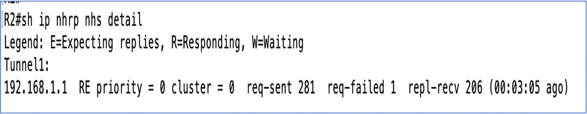
Figure 5-13 Output of the Command show crypto ipsec sa
With each of the commands shown in Figure 5-12 and Figure 5-13, if you add the word detail at the end, the output shows more detailed counters. (For more troubleshooting commands and techniques, see the IPsec troubleshooting documentation listed at the end of the chapter.)
Troubleshooting the GRE Tunnel Configuration
The configuration of a tunnel in a DMVPN solution is somewhat different from the configuration of a tunnel used to repair a discontinuous OSPF area. In DMVPN tunnel configuration, you only have a tunnel source and not a tunnel destination. This is because the tunnel is configured to support NHRP configuration. The hub is dynamic, so it is waiting for inbound registrations and does not need a tunnel destination. The spokes have the destination of the tunnel endpoint mapped to the public IP address in the nhrp command in Example 5-12 for IPv4 and Example 5-13 for IPv6.
Validating the Tunnel
You must validate that the tunnel state is up/up, and after you apply the tunnel source command and enable the tunnel interface. You need to make sure you have selected the correct tunnel source interface. In Example 5-11, it is the outside IP address. (This is a common mistake in configuring tunnel interfaces.) In addition, you need to make sure you have the tunnel configured as an mGRE tunnel, especially on the hub side. If you’re using a tunnel key, both sides need to be the same.
Figure 5-14 shows the command show ip interface brief executed on the Spoke1 router. This validates that the Tunnel1 interface is in the up/up state.
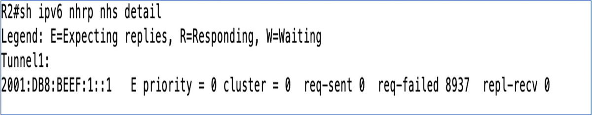
Figure 5-14 Output of the Command show ip interface brief on an IPv4 Interface
Troubleshooting the NHRP Hub-and-Spoke Configuration
NHRP troubleshooting starts with issuing two basic commands on the spoke router. First, you need to determine if the VPN tunnel is up and functioning correctly. If it isn’t, you need to determine whether IKE phase 1 or IKE phase 2 is failing. If the tunnel is up when you issue show crypto isakmp sa, you should see QM_IDLE. If you see only encapsulations and not decapsulations, you know you have either a crypto ISAKMP Phase 2 problem or an NHRP registration issue.
NHRP Registration
You must determine whether the NHRP spoke is registering. The command show ip nhrp nhs detail, shown in Figure 5-15, tells you whether you have both sent and received packets from the NHRP NHS. If you see that the request has been sent (req-sent) but no replies have been received (repl-recv) and the request failed (req-failed) count is increasing, then you know you have an NHRP spoke that is unable to register with the NHS.
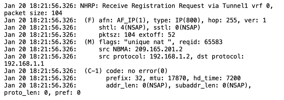
Figure 5-15 Output of the Command show ip nhrp nhs detail
Tunnel Configuration
It is important to validate that the configuration of the tunnel interface is correct. Take a look at Figure 5-15, and make sure you have the correct information on the NHS, which in this example is the IP address of the tunnel interface of the hub router. This is the first area that might be misconfigured. Check your documentation and make sure this address is correct. Then verify that the command ip nhrp map references the tunnel address first, followed by the outside IP address (NBMA) of the hub router.
Figure 5-16 shows the command show ipv6 nhrp nhs detail executed on the Spoke1 router. The output provides information on the IPv6 address of the tunnel interface for the NHRP server. It validates that the NHRP configuration information on the spoke is valid.
Figure 5-16 Output of the Command show ipv6 nhrp nhs detail
Debugging
If you determine that so far everything is correct, you can turn on debugging for NHRP packets on the hub router to see if they are being received by the NHS and why the NHS cannot respond. You can force a registration attempt by shutting down the tunnel interface on the spoke router and then reenabling it. If you have debugging enabled on the hub router, you should see an inbound registration request.
Figure 5-17 shows the command debug nhrp packet executed on the NHRP server router. This also validates that the spoke router is attempting to register with the NHRP server. If you do not see inbound registration requests, then there is probably a misconfiguration of the NHRP server parameters on the spoke router.
Figure 5-17 Output of the Command debug nhrp packet
In the debug screen shown in Figure 5-17, you can see that the inbound registration request comes via the tunnel interface and includes the source NBMA IP address (the outside address) and the source protocol IP address (the tunnel address). In addition, it includes the destination protocol addresses. Each of these fields provides a good indication about whether the configuration on the host side is aligned with the hub router configuration.
Troubleshoot the Routing Configuration
Troubleshooting the routing protocol part of the DMVPN tunnel is not very complex. The challenge is whether you are able to see routes of other remote sites in the routing table. The first command to issue is show ip protocol. This command shows what IP blocks are being advertised. You should compare the spoke side to what the hub side is seeing in the routing table. If you execute show ip route and do not see the route in the table, then you should verify both the EIGRP autonomous system number and whether you have any security on the route exchanges. In addition, you should check to see if the hub router is summarizing the routes into a larger block. Finally, you should check to see what EIGRP neighbors the hub router identifies.
DMVPN Troubleshooting Summary
Table 5-3 consolidates some of the key commands covered so far, as well as a few more that are valuable for troubleshooting. The commands are organized in this table in the same parts as the DMVPN implementation shown in this chapter. Even if you configure your solution correctly the first time, it is good to use these commands to understand what the Cisco routers are doing in each of the phases.
Table 5-3 DMVPN Troubleshooting Commands


That wraps up troubleshooting DMVPN troubleshooting fundamentals. Keep in mind troubleshooting makes up a major part of the SVPN exam.
Summary
This chapter introduced DMVPN technology and its features. It also described the components needed for DMVPN and looked at two of the key components, mGRE and NHRP. We covered the features, benefits, and limitations of mGRE and NHRP, especially related to routing and security. We discussed both IPv4 and IPv6 DMVPN configuration because both are deployed and could be found within the SVPN exam. Finally, this chapter covered some potential pitfalls and challenges related to deploying a DMVPN solution.
At this point, you should have a strong foundation for planning, configuring and managing GETVPN as well as DMVPN deployments. Next up is a deep dive into FlexVPN, wrapping up our focus on site-to-site VPN concepts.
References
Brandom, Russel (May 12, 2017). UK Hospitals Hit with a Massive Ransomware Attack. Retrieved from https://www.theverge.com/2017/5/12/15630354/nhs-hospitals-ransomware-hack-wannacry-bitcoin
Dynamic Multipoint VPN Configuration Guide, Cisco IOS Release 15M&T. Retrieved from https://www.cisco.com/c/en/us/td/docs/ios-xml/ios/sec_conn_dmvpn/configuration/15-mt/sec-conn-dmvpn-15-mt-book/sec-conn-dmvpn-tun-mon.html#GUID-E968E183-0022-4E8C-89A6-69AE3AE2AFF9
Dynamic Multipoint VPN Configuration Guide, Cisco IOS Release 15S. Retrieved from https://www.cisco.com/c/en/us/td/docs/ios-xml/ios/sec_conn_dmvpn/configuration/15-s/sec-conn-dmvpn-15-s-book/ip6-dmvpn.html#GUID-AE87E1CC-DF83-426D-885C-2E00CF365833
GRE Tunnel Interface States and What Impacts Them, Retrieved from https://www.cisco.com/c/en/us/support/docs/ip/generic-routing-encapsulation-gre/118361-technote-gre-00.html
IP Addressing: NHRP Configuration Guide. Retrieved from https://www.cisco.com/c/en/us/td/docs/ios-xml/ios/ipaddr_nhrp/configuration/xe-3s/nhrp-xe-3s-book/config-nhrp.html
IPsec Troubleshooting: Understanding and using debug Commands. Retrieved from https://www.cisco.com/c/en/us/support/docs/security-vpn/ipsec-negotiation-ike-protocols/5409-ipsec-debug-00.html
Scalable DMVPN Design and Implementation Guide. Retrieved from https://www.cisco.com/c/dam/en/us/products/collateral/security/dynamic-multipoint-vpn-dmvpn/dmvpn_design_guide.pdf?dtid=osscdc000283
Transform Set Configuration. Retrieved from https://www.cisco.com/c/en/us/td/docs/wireless/asr_5000/21/IPSec/21_IPSec-Reference/b_21_IPSec_chapter_0100.pdf
Kingsbury, Josh, DMVPN – Concepts & Configuration. Retrieved from https://learningnetwork.cisco.com/s/article/dmvpn-concepts-amp-configuration
Coran, Matt, Design Guide | DMVPN Phases. Retrieved from https://network-insight.net/2015/02/design-guide-dmvpn-phases/
Exam Preparation Tasks
As mentioned in the section “How to Use This Book” in the Introduction, you have a couple of choices for exam preparation: the exercises here, Chapter 11, “Final Preparation,” and the exam simulation questions in the Pearson Test Prep software online.
Review All Key Topics
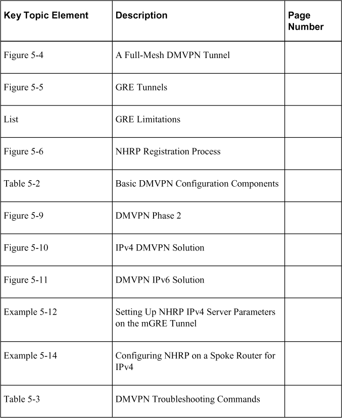
Review the most important topics in the chapter, noted with the key topics icon in the outer margin of the page. Table 5-4 lists these key topics and the page number on which each is found.
Table 5-4 Key Topics for Chapter 5
Complete Tables and Lists from Memory
Print a copy of Appendix C, “Memory Tables” (found on the companion website), or at least the section for this chapter and complete the tables and lists from memory. Appendix D, “Memory Tables Answer Key” (also on the companion website), includes completed tables and lists to check your work.
Define Key Terms
Define the following key terms from this chapter and check your answers in the glossary: