
Chapter 6. Information Systems Used for IT Delivery and Support
This chapter helps you prepare for the Certified Information Systems Auditor (CISA) exam by covering the following ISACA objectives, which include understanding the importance of system infrastructure and control. This includes items such as the following:
Tasks
Evaluate the use of capacity and performance monitoring tools and techniques to ensure that IT services meet the organization’s objectives.
Evaluate problem and incident management practices to ensure that incidents, problems or errors are recorded, analyzed, and resolved in a timely manner.
Evaluate the functionality of the IT infrastructure (e.g., network components, hardware, system software) to ensure it supports the organization’s objectives.
Knowledge Statements
Knowledge of systems performance monitoring processes, tools, and techniques (e.g., network analyzers, system utilization reports, load balancing)
Knowledge of the functionality of hardware and network components (e.g., routers, switches, firewalls, peripherals)
Network Standards and Protocols
Network Services and Applications
Comparing the OSI Model to the TCP/IP Model
Network Administration and Control
Risks to Network Infrastructure and Controls
This chapter addresses information you need to know about service delivery. An array of equipment, transmission protocols, and devices operate as the heartbeat of modern organizations. Although this array is transparent to most employees, these systems deliver email, provide connectivity to the Internet, allow file sharing, and support print services and a range of other services. Auditors must understand these complex systems. Listed here are some of the primary topics a CISA candidate should review for the exam:
![]() Understand how to analyze network capacity
Understand how to analyze network capacity
![]() Know the ways in which performance is measured
Know the ways in which performance is measured
![]() Know how to analyze a network and verify that it meets the needs of the organization
Know how to analyze a network and verify that it meets the needs of the organization
![]() Describe basic network equipment such as hubs, switches, routers, and firewalls
Describe basic network equipment such as hubs, switches, routers, and firewalls
![]() Describe LAN, WAN, and networking protocols including TCP/IP, Frame Relay, X.25, wireless, and so on
Describe LAN, WAN, and networking protocols including TCP/IP, Frame Relay, X.25, wireless, and so on
Introduction
This chapter introduces networking technology. Not all networks are created equal. Different protocols are used on local area networks (LANs), metropolitan area networks (MANs), and wide area networks (WANs). Some of these protocols, such as Transmission Control Protocol/Internet Protocol (TCP/IP), might be familiar to you; however, others, such as Frame Relay, X.25, or Asynchronous Transfer Mode (ATM), might not. The CISA must understand these protocols and the equipment that interconnects the network. These components include hubs, bridges, switches, routers, and firewalls. The design of the network and the type of equipment used can have a big impact on the level of security provided. An IS auditor must be aware of these issues and also be able to examine the level of services provided by the network. In addition, auditors must be able to determine the capacity constraints of the network. Just as every modern freeway has a maximum level of capacity, so does the network. It is important to know the current demand and expected future demand requirements. This knowledge provides for the proper planning and budgeting of current and future control requirements. This chapter begins by examining network architectures and the types of networks.
Network Infrastructure
Knowledge Statement
![]() Knowledge of the functionality of hardware and network components (e.g., routers, switches, firewalls, peripherals)
Knowledge of the functionality of hardware and network components (e.g., routers, switches, firewalls, peripherals)
The network infrastructure encompasses all the protocols, hardware, and systems used to provide network services. Networks can be local or distant. Local networks must use an agreed-upon set of protocols and a standardized cabling method. This might be coaxial cable, twisted-pair cable, or even a wireless system. Distant networks must also have an agreed-upon way to communicate with other distant systems. They, too, need cabling and protocols to operate. Without agreed-upon standards, the Internet would not be possible. TCP/IP is one of these common protocols. The equipment to connect all these systems must also be capable of interacting with the various protocols and communication schemes. Routers are one such piece of equipment. Routers form the backbone of the Internet. The following section begins to examine the concepts behind network infrastructure more deeply by first defining the different network types.
Network Types
Throughout time, there has always been a need to share information. Years ago, that might have been by paper, fax, or phone. Today the computer network has taken over that task. The development of the desktop computer in the 1980s caused a paradigm shift. Much of this change would not have been possible without the capability to link these desktop PCs together. Some of this work had been done decades earlier. Back in 1975, the Digital, Intel, and Xerox (DIX) group released the first official Ethernet product. Ethernet is the standard for local area networks (LANs). The computers and other devices in a LAN communicate over a small geographical area, such as the following:
![]() A section of a one-story building
A section of a one-story building
![]() The whole floor of a small building
The whole floor of a small building
![]() Several buildings on a small campus
Several buildings on a small campus
![]() A work office or home network of computers
A work office or home network of computers
Note
The Father of the Ethernet Robert Metcalfe is commonly referred to as the Father of the Ethernet. The first designs for the protocol were created in 1975 at a National Computer Conference. Metcalfe went on to form 3Com, a successful networking equipment company.
Although it is nice to have computers and other networked devices communicate locally, many times the need exists to communicate on a larger scale. For devices that need to communicate on a citywide level, the metropolitan area network (MAN) was created. The MAN is a network that interconnects a region larger than what’s covered by a LAN. A MAN can include a city, geographic region, or large area. If you work for a company that owns several buildings located in different states or countries, that network is part of a wide area network (WAN). A WAN spans geographic distances that are too large for LANs and MANs. WANs are connected by routers. When two LANs are connected over a distance, they form a WAN. You might think this covers just about all the possible different network types, but a few more are worth mentioning. One such type is the personal area network (PAN), which allows a variety of personal and handheld electronic devices to communicate over a short range. A subset of the PAN is known as a wireless PAN (WPAN). Bluetooth is one technology that makes use of WPANs. The three classifications of Bluetooth include the following:
![]() Bluetooth Class 1—Up to 100m of range and 100mW of power
Bluetooth Class 1—Up to 100m of range and 100mW of power
![]() Bluetooth Class 2—Up to 20m of range and 2.5mW of power
Bluetooth Class 2—Up to 20m of range and 2.5mW of power
![]() Bluetooth Class 3—Up to 10m of range and 1mW of power
Bluetooth Class 3—Up to 10m of range and 1mW of power
Finally, there are storage area networks (SANs). A SAN is a network of storage disks and devices. SANs are used to connect multiple servers to a centralized pool of disk storage. SANs improve system administration by allowing centralizing storage instead of having to manage hundreds of servers, each with its own disks.
Network Standards and Protocols
Task
![]() Evaluate the use of capacity and performance monitoring tools and techniques to ensure that IT services meet the organization’s objectives.
Evaluate the use of capacity and performance monitoring tools and techniques to ensure that IT services meet the organization’s objectives.
Communication systems need some type of model for devices to communicate and understand what the other devices need. Over the years, various standards have been developed to make this possible. These standards and protocols set up rules of operation. Protocols describe how requests, messages, and other signals are formatted and transmitted over the network. The network will function as long as all computers are consistent in following the same set of rules for communication. Protocols, such as TCP/IP, and standards, such as the Open Systems Interconnect (OSI), are two examples of network rules. These rules have helped build the Internet and the worldwide data networks we have today. The goal of any set of network standards is to provide the following:
![]() Interoperability
Interoperability
![]() Availability
Availability
![]() Flexibility
Flexibility
![]() Maintainability
Maintainability
Many groups have been working toward meeting this challenge, including the following:
![]() International Organization for Standardization (ISO)
International Organization for Standardization (ISO)
![]() American Institute of Electrical and Electronics Engineers (IEEE)
American Institute of Electrical and Electronics Engineers (IEEE)
![]() Internet Engineering Task Force (IETF)
Internet Engineering Task Force (IETF)
![]() International Telecommunications Union–Telecommunications Sector (ITU-T)
International Telecommunications Union–Telecommunications Sector (ITU-T)
The next section discusses one of these organizations, the ISO, in greater detail.
The OSI Model
The ISO is recognized for its development of the Open Systems Interconnect (OSI) reference model. The ISO set the worldwide standards for its work in developing a common approach to networking. Its goal was for all vendors to adopt its standard networking architecture for all hardware and software products, thereby enabling all network users to communicate with each other regardless of the computer products owned or used. The OSI model was developed in 1984 and defines networking as a seven-layer process. Within the OSI model, the data is passed down from layer to layer. It begins at the application layer and ends at the physical layer, as shown in Figure 6.1. The data is then transmitted over the medium toward the target device, back up the stack to the application layer of the target machine. The seven layers of the OSI model are: application, presentation, session, transport, network, data link, and physical.
Most people remember the OSI model by one of the many acronyms that have been thought of over the years. One way to remember it is to use the following mnemonic device:
All (application—Layer 7)
People (presentation—Layer 6)
Seem (session—Layer 5)
To (transport—Layer 4)
Need (network—Layer 3)
Data (data link—Layer 2)
Processing (physical—Layer 1)
Today the OSI model is widely used as a guide in describing the operation of a networking environment and serves as a teaching model for all other protocols. The following sections describe and examine how each layer of the OSI model is designed to operate. Let’s get started by reviewing the application layer and then working our way down the stack.
Exam Alert
The OSI Model CISA candidates need to know the seven layers of the OSI model (from Layer 1 to Layer 7): physical, data link, network, transport, session, presentation, and application layer.
The Application Layer
Layer 7 is known as the application layer. Recognized as the top layer of the OSI model, this layer serves as the window for application services. This is the layer that users are most knowledgeable of. The application layer serves as the interface for applications, such as email and web browsers. Without the application layer, email and the Web would not exist and our computers would be unable to interpret and sort the data transmitted by other computers. Layer 7 is not the application itself, but rather the channel through which applications communicate. Think of this in terms of preparing to send a present to a friend—the application layer would be equivalent to buying the gift.
The Presentation Layer
Layer 6 is known as the presentation layer. Consider the gift analogy from the preceding section. At Layer 6, this is when you are now ready to take the gift to the post office. It will require packaging. Although some might be content in placing the gift in a paper package, the post office will require a specific type of box if you want to send the gift by priority mail. This means that the presentation layer is concerned about presentation. Data must be formatted so the application layer can understand and interpret the data. The presentation layer is skilled in translation; its duties include encrypting data, changing or converting the character set, and performing protocol conversion. Data compression is also performed at the presentation layer.
The Session Layer
Layer 5 is known as the session layer. Its purpose is to allow two applications on different computers to establish and coordinate a session. A session is simply a name for a connection between two computers. Ports are defined at the session layer. Ports are used to identify the application being used. For example, port 21 is used for File Transfer Protocol (FTP), and port 80 is used for Hypertext Transfer Protocol (HTTP). When a data transfer is completed, the session layer is responsible for tearing down the session.
The Transport Layer
Layer 4 is known as the transport layer. While the network layer routes your information to its destination, the transport layer ensures completeness by handling end-to-end error recovery and flow control. Without the transport layer, the network would be unreliable. Transport-layer protocols include (1) Transmission Control Protocol (TCP), a connection-oriented protocol that provides reliable communication through the use of handshaking, acknowledgments, handling error detection, and session teardown; and (2) User Datagram Protocol (UDP), a protocol without a connection that offers speed and low overhead as its primary advantage. As an example, when I take my package to the post office, I must now decide how to ship it. Should I send it return receipt with delivery confirmation (TCP), or shall I just pay for parcel post (UDP) and hope it gets there?
The Network Layer
Layer 3 is known as the network layer. The network layer is tied to routers and routing. The network layer is responsible for the movement of data from network A to network B. The network layer is the home of the Internet Protocol (IP). IP acts as a postman determining the best route from the source to the target network. Like a postman, IP does not examine the contents of the packet (letter or package); it simply makes a best effort at delivery. Network-layer components include the following:
![]() Routers
Routers
![]() Routing protocols
Routing protocols
![]() Packet filters
Packet filters
The Data Link Layer
Layer 2 is known as the data link layer. The data link layer is responsible for formatting and organizing the data before sending it to the physical layer. It is also responsible for error handling. The data link layer must frame up packets and deal with the local delivery of traffic within a single LAN. A frame is a logical structure in which data can be placed. When a frame reaches the target device, the data link layer is responsible for stripping off the data frame and passing the data packet up to the network layer. Data link–layer components include the following:
![]() Bridges
Bridges
![]() Switches
Switches
![]() Network interface cards (NICs)
Network interface cards (NICs)
![]() Media Access Control (MAC) addresses
Media Access Control (MAC) addresses
The Physical Layer
Layer 1 is known as the physical layer. Bit-level communication occurs here. The bits have no defined meaning on the wire, but the physical layer defines how long each bit lasts and how it is transmitted and received. All the electrical, mechanical, and functional requirements of the network are specified at this level. The physical layer even establishes parameters to define whether a data bit is a one or zero. Returning to our previous example, this is where your package and many others are all loaded on the mail carrier’s truck and bound for delivery. Physical-layer components include the following:
![]() Copper cabling
Copper cabling
![]() Fiber cabling
Fiber cabling
![]() Wall jacks and connectors
Wall jacks and connectors
![]() Ethernet hubs
Ethernet hubs
Exam Alert
OSI Layer Functionality Before taking the exam, make sure you understand what types of functions occur at each layer of the OSI model. As an example, the transport layer is home to both TCP and UDP.
At the bottom of the OSI model or stack, the data is broken into electrical signals and transmitted on the fiber, wire, or wireless system used. When the targeted system receives it, the information is pushed back up the stack until it arrives at the application layer and is passed to the appropriate service. Figure 6.2 illustrates this process.
Figure 6.2 Processing data with the OSI model.

Network Services and Applications
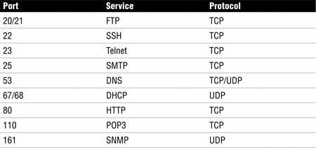
Networks can provide a wide array of applications and enable users to share common services such as file sharing. Networks give users the capability to share files and folders with other users. Users can have read, write, or full control. A common means of sharing files remotely is File Transfer Protocol (FTP), an application used to move files from one computer to another. FTP operates on ports 20 and 21. Email service is another common network service and one of the most widely used network services. Email uses two protocols. Simple Mail Transfer Protocol (SMTP) is the first. SMTP is designed for the exchange of electronic mail between network systems. All types of computers can exchange messages with SMTP. It operates on port 25. The second protocol used by email is Post Office Protocol version 3 (POP3), which provides a simple, standardized way for users to access mail and download messages from a mail server to their own computer. POP3 operates on port 110.
Print services are another well-used network service. Print services enable users to use network printers to manage and print documents to remote network printers. Terminal-emulation software (TES) is a category of network service that enables users to access remote hosts. These hosts then appear as local devices. An example of TES is Telnet, which allows a client at one site to establish a session with a host at another site. The program passes the information typed at the client’s keyboard to the host computer system. Telnet sends passwords and other information in clear text. Telnet operates on port 23.
The network-management service is used to control and maintain the network. IT does so by monitoring the status of devices and reporting this information back to a management console. Network-management services allow the effective use of the network and help alert staff of problems before they become critical. Simple Network Management Protocol (SNMP) is the protocol commonly used for network management. SNMP was designed to be an efficient and inexpensive way to monitor networks. The SNMP protocol allows agents to gather information. The agent gathers network statistics and reports it back to its management station. Most corporations use some type of SNMP management. SNMP operates on port 161.
Directory services are the means by which network services are identified and mapped. Directory services perform services similar to that of a phone book as it correlates addresses to names. An example of directory services can be seen in the Domain Name Service (DNS), which performs address translation. DNS converts fully qualified domain names (FQDNs) into a numeric IP address. An example of a FQDN is www.thesolutionfirm.com. DNS can take this name and resolve its proper IP address, 112.10.8.5. DNS operates on port 53.
No discussion on network services would be complete without mentioning the Internet and the Hypertext Transfer Protocol (HTTP). HTTP has helped make the Web the popular tool it is today. The HTTP connection model is known as a stateless connection. HTTP uses a request/response protocol in which a client sends a request and a server sends a response. HTTP operates on port 80.
Comparing the OSI Model to the TCP/IP Model
Although the OSI model was great in theory, it was never fully implemented. Instead, TCP/IP was implemented in its place. TCP/IP is the foundation of computer communications. Its development can be traced back to the U.S. Department of Defense (DoD). TCP/IP is similar to the OSI model but consists of only four layers instead of seven, as illustrated in Figure 6.3.
Figure 6.3 TCP/IP, OSI model, and related services.

The Network Access Layer
The network access layer corresponds to Layers 1 and 2 of the OSI model. The network access layer is responsible for physical delivery of IP packets via frames. The most common frame type is Ethernet. Ethernet is a CSMA/CD (Carrier Sense Multiple Access/Collision Detection) technology that places data into frames. Frames contain the source and destination addresses and are referred to as Media Access Control (MAC) addresses. MAC addresses are 6 bytes long. Most tools such as analyzers display MAC addresses in hexadecimal, which look something like this: 00 00 0C 12 34 67. The information found in the Ethernet header and trailer is 18 bytes total. Ethernet frames can carry between 46 and 1,500 bytes of data.
Token Ring is the second most used LAN protocol after Ethernet. Whereas Ethernet is a collision-detection protocol, Token Ring is a collision-avoidance protocol. As an example, consider going to a noisy party with your friends. Everyone’s talking and the only way to be heard is by waiting for a brief period of slience and then jumping into the conversation. That’s how Ethernet works—it’s contention-based. Ethernet is quite different from Token Ring. A collision-avoidance protocol such as Token Ring is like going to a very reserved dinner party with your CEO and senior management. Everone is very reserved and as long as one person is talking, everyone else stays silent and waits for their turn to speak. This type of protocol is deterministic as the only one that can speak is the one with the token. The Point-to-Point Tunneling Protocol (PPTP) is also found at the network access layer. PPTP is used to tunnel private information over the public Internet and is widely used in virtual private network (VPN) products.
The Internet Layer
The internet layer maps to OSI Layer 3. This layer contains the information needed to make sure the data can be routed through an IP network. Whereas MAC addresses are considered a physical address, an IP address is considered a logical address. IP divides networks into logical groups known as subnetworks (subnets). IPv4, the current version of IP, uses 32-bit addresses. These addresses are laid out in a dotted-decimal notation. The IPv4 address format is four decimal numbers separated by decimal points. Each of these decimal numbers is 1 byte in length, to allow numbers to range from 0 to 255. Three primary ranges of logical addresses are used:
![]() Class A networks—Class A networks consist of up to 16,777,214 client devices; their address range can extend from 1 to 126.
Class A networks—Class A networks consist of up to 16,777,214 client devices; their address range can extend from 1 to 126.
![]() Class B networks—Class B networks host up to 65,534 client devices; their address range can extend from 128 to 191.
Class B networks—Class B networks host up to 65,534 client devices; their address range can extend from 128 to 191.
![]() Class C networks—Class C networks can have a total of 245 devices; their address range can extend from 192 to 223.
Class C networks—Class C networks can have a total of 245 devices; their address range can extend from 192 to 223.
Note
IPv6 The next version of IP is IPv6. Although it might not be seen in many places in the U.S. yet, it is much more common in Europe. Besides offering better security, IPv6 also features 128-bit addressing, which allows for the growing need for IP addresses for many years.
If the internet layer deals with logical addresses and the network access layer deals with physical addresses, how do the two layers communicate? These two layers overcome these problems by using the Address Resolution Protocol (ARP). The purpose of ARP is to map known IP addresses to unknown MAC addresses. This two-step process is performed by first sending a message to all devices on the LAN requesting the receiver’s physical address. If a device recognizes the address as its own, it issues an ARP reply to the sender of the ARP request. A good way to correlate the difference between physical and logical addresses is to think of the postal service. As an example, if I were to send a postcard to my mom, I would need to place her physical address on the postcard, such as 1313 Mockingbird Lane. I also need a logical address to place on the postcard—in this case, Betty Gregg. Together the logical address and the physical address allow delivery to the end address. Networks provide the capability to send information to more than one device at a time. Actually, there are three different ways to send data packets:
![]() Unicast—A packet transmitted from the sender to one receiver
Unicast—A packet transmitted from the sender to one receiver
![]() Multicast—A packet transmitted from the sender to a group of receivers
Multicast—A packet transmitted from the sender to a group of receivers
![]() Broadcast—A packet transmitted from the sender to all other devices on the network
Broadcast—A packet transmitted from the sender to all other devices on the network
The internet layer is also where some routing protocols reside. Routing protocols direct packets toward their intended destination. Routing protocols are based on distance or link state. Distance-vector protocols make a decision on the best route to the destination by determining the shortest path, calculated by counting hops. Each router counts as one hop. Routing Information Protocol (RIP) is one of the most well-known distance-vector protocols. A major shortcoming of a distance-vector protocol is that the path with the lowest number of hops might not be the optimum route; the path with the lower hop count might have considerably less bandwidth than the one with the higher hop count. Link-state routing protocols are the second type of routing. Link-state protocols determine the best path by metrics, such as delay or bandwidth. Link-state routing is considered more robust than distance-vector routing. Open Shortest Path First (OSPF) is probably the most common link-state routing protocol and many times is used as a replacement to RIP.
Exam Alert
The Internet Layer Test candidates should be aware that the internet layer is primarily responsible for routing and logical addressing. Protocols such as IP and OSPF can be found at the internet layer.
The Host-to-Host Layer
The host-to-host layer corresponds to OSI Layers 4, 5, and 6. The host-to-host layer provides end-to-end delivery. This is accomplished by either the Transmission Control Protocol (TCP) or User Datagram Protocol (UDP).
TCP is a reliable protocol that provides for confirmed delivery of data. TCP gets its reliability by performing a three-step handshake before data is sent, using acknowledgments, and performing a four-step shutdown at the conclusion of communication, as illustrated in Figure 6.4.
Figure 6.4 TCP setup, data flow, and shutdown.

UDP provides unconfirmed delivery and offers none of the handshaking process that is performed with TCP. Although this lowers reliability, it increases speed. UDP offers no guarantee of delivery and is used for applications and services that require speed. An example of a UDP application is voice over IP (VoIP), illustrated in Figure 6.5.
Figure 6.5 UDP communication flow.

The Application Layer
The application layer maps to OSI Layers 6 and 7. The application layer is responsible for application support. Applications are typically mapped not by name, but by their corresponding port. Ports are placed into TCP and UDP packets so the correct application can be passed to the required protocols below.
Although a particular service might have an assigned port, nothing specifies that services cannot listen on another port. An example of this is HTTP, whose assigned port is 80. Your company might decide to run this on another port, such as 8080. As long as your web browser knows on what port to find the application, this will not present a problem. Standard ports are used primarily to make sure that services can be easily found. Table 6.1 lists some common ports.
Two common network services found at the application layer are the Domain Name Server (DNS) and Dynamic Host Configuration Protocol (DHCP). DNS performs address translation by resolving known fully qualified domain names (FQDNs) to IP addresses. DNS uses UDP for DNS queries (resolutions) and TCP for zone transfers. DHCP is used to provide IP addresses automatically. DHCP also provides the DNS server, gateway IP address, and subnet mask to a local system upon startup if it is configured to use DHCP. This four-step process is described in more detail here:
6.1 Dynamic Host Configuration Protocol Operation
1. You can remember the DHCP process with the mnemonic DORA: discovery, offer, request, and acceptance. The first step is discovery. At this step, the host initially sends a broadcast in an attempt to discover a DHCP server on the network.
2. The second step is the offer. At this step, the DHCP server detects the computer that is looking for the DHCP service and responds with an offer of an IP address.
3. The third step is the request. At this step, the client receives the offer on an address and, in most cases, accepts it. To accept, the client must send an official request for the same IP address offered previously by the DHCP server.
4. The fourth step is the acceptance. At this step, the DHCP server completes the transaction by sending an acceptance message and marking the particular IP address “in use” for the specific host.
Network Design
Networks can use a variety of topologies. The topology is the physical design of the network. Topologies include bus, star, ring, and mesh. Table 6-2 provides an overview of each topology.
Table 6.2 Description and Features of Various Topologies

A bus topology consists of a single cable in which all computers are linked. The cable is terminated on each end. Older LAN technologies, such as 10BASE-5 and 10BASE-2, used a bus topology. Bus designs suffer problems ranging from low speeds to network outages because a single break can bring down the entire network. A star topology links each device via a hub or switch. Wires radiate outward from the switch in a starlike pattern. Although this design uses the most cable, a single break in a cable affects only one device. This is one of the most widely used LAN topologies. The ring topology is characterized by the fact that no endpoints or terminators exist. The layout of a ring network is that of a continuous loop of cable in which all networked computers are attached. Ring networks can span great distances and offer high performance. Token Ring and FDDI networks are two examples of protocols that use a ring topology. The mesh topology connects all devices with many redundant connections. This type of design offers the greatest amount of redundancy. The Internet is an example of a mesh network. Figure 6.6 illustrates each of these designs.
Figure 6.6 Common network designs.
Note
Network Redundancy Full-mesh networks provide the most protection against network failure. If each device has a separate link to each other, the network will provide the greatest amount of fault tolerance.
Network Cabling
Network topology and network cabling are closely associated, and both are part of network architecture. Cabling choices can include wire, fiber, and wireless systems. Although each approach has specific advantages, they all share some common disadvantages. One such disadvantage is attenuation, which is the reduction of signal. As the signal travels farther away from the transmitting device, the signal becomes weaker in intensity and strength. Therefore, all signals need periodic reamplification and regeneration.
Signals can be transmitted between devices in one of two basic methods:
![]() Baseband transmissions use a single channel to communicate. As an example, Ethernet uses a baseband transmission scheme. Baseband allows only one signal to be transmitted at any one time.
Baseband transmissions use a single channel to communicate. As an example, Ethernet uses a baseband transmission scheme. Baseband allows only one signal to be transmitted at any one time.
![]() Broadband uses many channels or frequencies. As an example, cable television is a broadband technology, as is a digital subscriber line (DSL). DSL broadband enables the user to make a phone call and surf the Internet at the same time.
Broadband uses many channels or frequencies. As an example, cable television is a broadband technology, as is a digital subscriber line (DSL). DSL broadband enables the user to make a phone call and surf the Internet at the same time.
Baseband and broadband systems need a transmission medium. If the choice is copper cable, the choices include coaxial and twisted-pair cables. Coaxial cable, widely used in the early days of networking, consists of a single solid copper wire core that uses a braided shield for the second conductor. Both conductors are covered with a plastic or insulative coating. Coaxial cable standards include 10BASE-5 (500 meters) and 10BASE-2 (185 meters). Twisted-pair cable (100 meters) is the more popular cabling choice. You can look in almost every wiring closet in any organization and find this type of cabling. Twisted-pair cable comes in many different speeds and is rated in categories. Category (Cat) 3 is 10Mbps, Cat 5 is 100Mbps, and Cat 6 is rated for 1Gbps. The primary difference between these cables is the number of twists per foot. The higher the twist counts, the greater the speed. The most common connector used is the RJ-45. Twisted-pair cable can be purchased in a shielded or unshielded version. Unshielded, which is known as UTP, is cheaper, but shielded cable, known as STP, does a better job at preventing interference.
Exam Alert
What’s Burning? Guarding the health and safety of employees is always a concern. Therefore, plenum-grade cable is designed for use in the crawl spaces of a building. Plenum-grade cable is coated with a fire-retardant coating and is designed to not give off toxic gasses and smoke as it burns.
Our next cabling option is fiber-optic cable. Whereas twisted-pair and coaxial cabling use copper wire, fiber uses strands of glass that carry light waves representing the data being transmitted. Fiber-optic cabling can be multimode or single mode. Multimode fiber-optic cabling usually is found in LANs and is powered by LEDs. Single-mode fiber-optic cable is powered by laser light and is used in WANs. Common fiber-optic standards include 10BASE-F, which is rated for 10Mbps, and 100BASE-FX, which is rated for 100Mbps.
Exam Alert
Fiber Is a Good Choice Fiber offers advantages over copper cable because it does not radiate signals and is harder to tap.
The final transmission method for discussion is wireless communication. Wireless systems can include wireless LAN protocols, such as 802.11b, 802.11g, and 802.11n. Each of these is designed for LANs and can transmit at speeds from 11Mbps to greater than 1Gbps. Advantages of these systems are that they can be set up easily and do not require a cable plant. Long-range wireless systems include radio systems, microwave radio systems, and satellite systems. Satellite systems have the capability to allow communications to span the globe, but they can introduce a delay because it takes about 300ms to transmit up to the satellite and back down to earth. Table 6.3 discusses each cabling option in more detail.

Choosing the right topology is important. Services such as VoIP and streaming video can place high demands on the network. To make sure the right infrastructure is deployed, the following questions should be asked:
![]() What applications will be used on the network?—Demanding applications require high performance. Ten Gigabit Ethernet, Gigabit Ethernet and Asynchronous Transfer Mode (ATM) are three possible choices.
What applications will be used on the network?—Demanding applications require high performance. Ten Gigabit Ethernet, Gigabit Ethernet and Asynchronous Transfer Mode (ATM) are three possible choices.
![]() What amount of bandwidth is needed?—Modern LANs demand increasing amounts of bandwidth. Virtual machines and increased Internet traffic raise the demand for bandwidth. Whereas 10Mbps connectivity with hubs was once sufficient, 100Mbps switched connectivity is now seen as the minimum.
What amount of bandwidth is needed?—Modern LANs demand increasing amounts of bandwidth. Virtual machines and increased Internet traffic raise the demand for bandwidth. Whereas 10Mbps connectivity with hubs was once sufficient, 100Mbps switched connectivity is now seen as the minimum.
![]() How much money does the company have to spend?—The price of network equipment has been declining for several years. However, the cost to recable a facility is high. This has led many companies to consider wireless as a real alternative.
How much money does the company have to spend?—The price of network equipment has been declining for several years. However, the cost to recable a facility is high. This has led many companies to consider wireless as a real alternative.
Note
Wireless Wireless can be considered problematic when it comes to security. Issues such as social engineering, MITM attacks, free Wi-Fi, and so on must be considered before making the move to wireless networking.
![]() Is remote management required?—Depending on the equipment purchased, it might or might not have the capability for remote management. The need for remote management must be balanced against the budget.
Is remote management required?—Depending on the equipment purchased, it might or might not have the capability for remote management. The need for remote management must be balanced against the budget.
Imagine that you have been asked to review your company’s cabling upgrade options. As an auditor, how would you describe the advantages and disadvantages of each of the potential solutions?
1. Complete this challenge by completing the following chart.

2. Use the information from the preceding sections to verify your answers.
Network Equipment
Before beginning any discussion on network equipment, we present some basic terms to ensure that you understand common issues related to network equipment. As discussed previously the most widely used LAN protocol is Ethernet. As a baseband technology, only one device can transmit at a time. Collisions occur when more than one device in the same collision domain attempts to transmit at the same time. Therefore, a collision occurs when two devices attempt to transmit at the same time. Collision domains are defined by the devices that share the same physical medium. As an example, Figure 6.6 displays a bus network with three computers. These three computers all share the same collision domain. Another term you should be aware of is broadcast domain. A broadcast domain is a group of devices that can receive other devices’ broadcast messages. Routers usually serve as the demarcation line for broadcast domains.
Now let’s work up the stack and discuss some of the various types of networking equipment. First up for review is the repeater, which is nothing more than an amplifier that can be used to extend the range of the physical network. A repeater receives the signal, regenerates the signal, and forwards it. Not far up the food chain above repeaters are hubs. Hubs are simply multiport repeaters that provide physical connectivity by allowing all the connected devices to communicate with one another. A hub is basically a common wire to which all computers have shared access. Hubs are on the decline because of their low maximum throughput and their security vulnerabilities. Collisions are a big problem with hubs—any time utilization approaches 20% or more, the number of collisions skyrockets and the overall average throughput decreases. Switches have replaced hubs.
One other older technology worth mentioning is the Layer 2 bridge. Bridges predate Layer 2 switches; they are software based and much slower than hardware-based switches. Bridges separate collision domains and act as a store-and-forward device. Another big problem with bridges is that they pass broadcast traffic. Much like hubs, bridges have mostly disappeared from the corporate network.
Layer 2 switches perform in much the same way as a hub, with the exception that switches segment traffic. They operate at the data link layer of the OSI model. Because of this design, each port on a switch is a separate collision domain. On an Ethernet, LAN switches segment traffic by observing the source and destination MAC address of each data frame. These MAC addresses are stored in a random access memory (RAM) lookup table, which can then be used to determine which port traffic should be forwarded to. The frame is forwarded to only that switch port; therefore, other ports never see the traffic. Switches provide higher throughput than a hub and can function in full duplex. Not all switches are made the same. Switch manufacturers have developed various ways to handle incoming frames, such as store-and-forward and cut-through. Store-and-forward waits for the frame to be completely inputted into the switch before forwarding. A cut-through design is faster because the frame is quickly forwarded to the targeted device.
Note
Layer 3 Switching Although traditionally switches are seen as Layer 2 devices, switches can be found at Layer 4 and work up to Layer 7. Higher-layer switches are known as content switches, content services switches, or application switches.
Routers reside at Layer 3 of the OSI model and are used to bridge dissimilar networks, join distant networks, and separate broadcast domains. Routers forward packets from one network to another based on network-layer information. For most networks, this information is an IP address. The IP address identifies the targeted host device. The router uses routing protocols to identify the best path from the source router to the destination device.
Closely related to routers are gateways. A gateway is a network device that is equipped for interfacing with another network that uses different protocols. In other words, gateways provide protocol conversion and, according to ISACA, can be found at Layer 4 and higher.
Modems are also a common piece of networking equipment. The word modem is short for modulate/demodulate. Modems convert a digital signal to an analog signal for transmission over the phone line. Modems are considered data communications equipment because they enable users to use phone lines to connect to distant computer networks. Modems are tasked with separating data into bits, synchronizing the signal with the distant computer, and then transmitting the sequence of bits sequentially.
The final piece of network equipment for review is the wireless access point (wireless AP). Wireless APs are used for LAN communication and started becoming popular in 2000. Wireless APs enable users to connect wireless devices to form a wireless network. Wireless APs are usually connected to a wired network and can relay data between wired and wireless devices. Table 6.4 provides an overview of the primary types of network equipment.
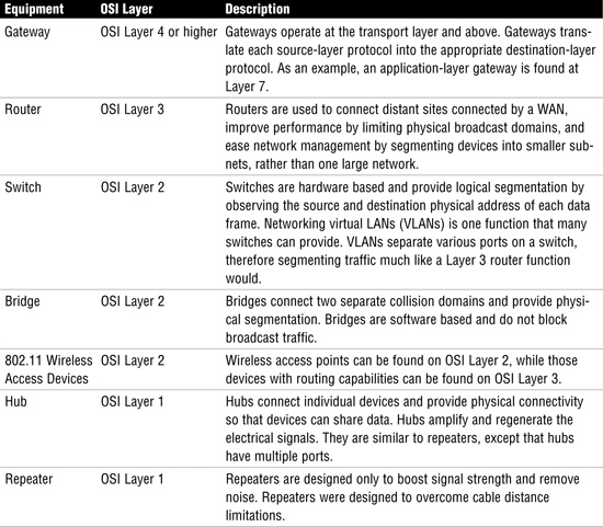
Exam Alert
Know Networking Equipment Exam candidates should understand what each piece of networking equipment does and where it fits into the OSI model. Know where devices operate.
Most likely, you are familiar with what this chapter has covered with the OSI model. In this challenge exercise, you fill in the layers of the OSI model and place the scrambled items in their proper position.
1. Review the items shown in Table 6.5.
Table 6.5 OSI Equipment and Protocols

2. Place the items shown in Table 6.5 in their proper order in Table 6.6.
Table 6.6 Blank OSI Challenge Table

3. Compare your answers as created in Table 6.6 to the completed Table 6.7.
Table 6.7 Completed OSI Challenge Table

Firewalls
The term firewall has been used since the 1990s and describes a device that guards the entrance to a private network. Firewalls were developed to keep out unauthorized traffic. Firewalls have undergone generations of improvements so that today several different types of firewall exist. These include the packet filter, application proxy, circuit proxy, and stateful inspection.
Packet filter firewalls operate at Layer 3 of the OSI model. Packet filters look at the packet header to determine whether to block or pass traffic. Packet filters can be thought of as the first generation of firewalls. They inspect the TCP/IP headers and make a decision based on a set of predefined rules. Packet filters simply drop packets that do not conform to the predefined rule set. These rules can include the following:
![]() Source IP address
Source IP address
![]() Destination IP address
Destination IP address
![]() TCP/UDP source port
TCP/UDP source port
![]() TCP/UDP destination port
TCP/UDP destination port
![]() TCP flags (SYN, FIN, ACK, and so on)
TCP flags (SYN, FIN, ACK, and so on)
Packet filters are considered stateless. This means that they store no information about the state of the session, which, in turn, means that packet filters are simple and fast but are vulnerable to attack. Spoofing is an example of a packet filter vulnerability.
One advancement in the firewall was the development of the proxy. By definition, the word proxy means “to stand in place of.” Therefore, a proxy is a hardware or software device that can perform address translation and communicates with the Internet on behalf of the network. The real IP address of the user remains hidden behind the proxy server. The host running the proxy service is known as an application gateway. Application proxies provide a higher level of security.
As you can see in the Step-by-Step 6.2, application proxies offer increased security because they don’t allow untrusted systems to have a direct connection to internal computers. Application proxies accept packets from the external network, copy the packets, inspect them for irregularities, change the addresses to the correct internal device, and then put them back on the wire to the destination device. An application proxy operates at Layer 7 of the OSI model. For the application proxy to work correctly, it must understand the protocols and applications with which it is working.
6.2 Application Proxy Process
1. The internal user generates a web request for www.yahoo.com.
2. The application proxy receives the request and alters the source address from the internal user to the address of the application proxy. The application proxy then forwards the request to the web server.
3. The web server www.yahoo.com receives the request and replies to the application proxy.
4. The application proxy checks its state table and uses this information to convert the destination address from the address of the application proxy to the address of the internal user. The data is inspected and then is forwarded to the internal user.
5. The internal user receives the data from www.yahoo.com from the application proxy.
Somewhere below an application proxy is a circuit-level proxy, which operates at Layer 5 of the OSI model. A circuit-level proxy closely resembles a packet-filtering device because it makes decisions on addresses, ports, and protocols. It does not provide the depth of security that an application-level proxy does because it does not inspect higher-layer applications. Its advantage is that it works with a wider range of protocols. Application proxies and circuit-level proxies do have something in common because both have the capability to maintain state. Stateful-inspection firewalls have the capability to keep track of every communication channel, with a state table. Because of this, they are considered an intelligent firewall. Packet filters do not have this capability.
Exam Alert
Application Proxy It is important to note that the application proxy provides the greatest level of protection because it inspects at all levels of the OSI model.
Firewall Configuration
Firewall configurations include packet filtering, dual-homed gateway, screened host, and screened subnet. A single-tier packet filter design has one packet-filtering router installed between the trusted and untrusted network, usually the Internet and the corporation’s network. The problems with this design become amplified as the network grows larger and because the packet filter has limited capabilities. Figure 6.7 illustrates this design.

A dual-homed gateway is an improvement over the basic packet-filtering router. Dual-homed gateways consist of a bastion host that has two network interfaces. One important item is that IP forwarding is disabled on the host. Additional protection can be provided by adding a packet-filtering router in front of the dual-homed host. Figure 6.8 illustrates this design.
Figure 6.8 Dual-homed gateway.
Note
Bastion Hosts The term bastion host has come to define the servers located in a DMZ or an untrusted area. These servers are designed much differently than those found in the internal network. Bastion hosts are typically hardened so that nonessential services are removed. Bastion hosts commonly perform tasks such as Web, email, DNS, and FTP.
The screened host firewall adds a router and screened host. The router is typically configured to see only one host computer on the intranet network. Users on the intranet have to connect to the Internet through this host computer, and external users cannot directly access other computers on the intranet. Figure 6.9 illustrates this design.

The screened subnet sets up a type of DMZ, a term that comes from the no man’s (demilitarized) zone that was set up between North and South Korea following the Korean War in the 1950s. DMZs are typically set up to give external users access to services within the DMZ. Basically, shared services such as the Internet, email, and DNS can be placed within a DMZ; the DMZ would provide no other access to services located within the internal network. Screened subnet and DMZs are the basis for most modern network designs. Figure 6.10 illustrates this firewall design.

Exam Alert
DMZ A DMZ offers the highest level of protection because defenses have been layered and shared services are placed in an area that prevents outsiders from fully entering the internal network.
All this talk of DMZs and screened subnets brings up one final issue—Network Address Translation (NAT). NAT allows a single device, such as a router or firewall, to act as an agent between the Internet and a local network. NAT was originally designed to deal with the shortage of IPv4 addresses. NAT is addressed in RFC 1631. Besides conserving public IP addresses, NAT provides security by providing address translation. This means that only a single, unique IP address is all that is needed to support an entire group of computers.
Wide Area Networks
Wide area networks (WANs) are much different than LANs. Whereas almost all companies own their LAN infrastructure, very few own their WAN infrastructure. Running a cable along the side of the interstate from Los Angeles to New York is usually not feasible. WANs and LANs also use very different protocols. WAN protocols are designed for the long-haul transmission of data. CISAs must understand WAN protocols and should focus on issues such as redundancy and fault tolerance. WAN protocols can be placed into two broad categories: packet switching and circuit switching.
Packet Switching
Packet-switched networks share bandwidth with other devices. They are considered more resilient and work well for on-demand connections with bursty traffic. Packet-switched protocols packetize data in much the same manner as the Ethernet or a Token Ring would. The data is placed into a frame structure. Let’s look at some different types of packet-switching protocols and services:
![]() X.25—Although it might sound like a government secret spy plane, X.25 is actually one of the original packet-switching technologies. It was developed in 1976 and operates at the physical, data link, and network layers of the OSI model. Once used extensively, X.25 is no longer widely used. X.25 has speeds of up to 56Kbps and is considered reliable.
X.25—Although it might sound like a government secret spy plane, X.25 is actually one of the original packet-switching technologies. It was developed in 1976 and operates at the physical, data link, and network layers of the OSI model. Once used extensively, X.25 is no longer widely used. X.25 has speeds of up to 56Kbps and is considered reliable.
![]() Frame Relay—Think of this technology as the son of X.25. Frame Relay improved upon X.25 and relies more on the upper layers of the OSI model for error handling. Frame Relay controls bandwidth usage by use of a committed information rate (CIR). The CIR specifies the maximum guaranteed bandwidth that the customer is guaranteed. Although higher rates might be possible, the CIR represents the level the service provider is committed to providing. If additional bandwidth is available, the data will pass; if no additional bandwidth is available, the data is marked with discard eligibility and discarded.
Frame Relay—Think of this technology as the son of X.25. Frame Relay improved upon X.25 and relies more on the upper layers of the OSI model for error handling. Frame Relay controls bandwidth usage by use of a committed information rate (CIR). The CIR specifies the maximum guaranteed bandwidth that the customer is guaranteed. Although higher rates might be possible, the CIR represents the level the service provider is committed to providing. If additional bandwidth is available, the data will pass; if no additional bandwidth is available, the data is marked with discard eligibility and discarded.
![]() Asynchronous Transfer Mode (ATM)—This cell-switching technology operates at the data link layer of the OSI model. ATM is an asynchronous protocol that supports classes of service. ATM provides high bandwidth for bursty traffic and works well for time-sensitive applications. Because the switching process occurs in hardware, delays are minimized. ATM can be used on LANs or WANs.
Asynchronous Transfer Mode (ATM)—This cell-switching technology operates at the data link layer of the OSI model. ATM is an asynchronous protocol that supports classes of service. ATM provides high bandwidth for bursty traffic and works well for time-sensitive applications. Because the switching process occurs in hardware, delays are minimized. ATM can be used on LANs or WANs.
![]() Multiprotocol Label Switching (MPLS)—MPLS is a framework that provides for the efficient switching of traffic flows through IP, ATM, and Frame Relay networks. Addresses are read just once as the packet enters the cloud, thereby providing more efficient routing. MPLS features class-of-service so that packets can be prioritized.
Multiprotocol Label Switching (MPLS)—MPLS is a framework that provides for the efficient switching of traffic flows through IP, ATM, and Frame Relay networks. Addresses are read just once as the packet enters the cloud, thereby providing more efficient routing. MPLS features class-of-service so that packets can be prioritized.
Note
Voice over IP (VoIP) Although it is not a packet-switching protocol, VoIP is carried on packet-switched networks in IP packets. Networks that have been configured to carry VoIP treat voice communications as just another form of data. Auditors should be aware of VoIP because of its security issues such as eavesdropping, the potential for denial of service, and also because loss of the data network can disable VoIP.
Circuit Switching
Circuit switching is the second type of WAN technology up for discussion. Telecommunication providers have used circuit switching since 1891, when a Kansas City undertaker patented the first one. The most common form of circuit switching is the plain old telephone service (POTS).
![]() POTS—This humble voice-grade analog telephone service is used for voice calls and for connecting to the Internet and other locations via modem. Modem speeds can vary from 9,600bps to 56Kbps. Although the POTS service is relatively inexpensive, very reliable, and widely available, it offers only low data speeds.
POTS—This humble voice-grade analog telephone service is used for voice calls and for connecting to the Internet and other locations via modem. Modem speeds can vary from 9,600bps to 56Kbps. Although the POTS service is relatively inexpensive, very reliable, and widely available, it offers only low data speeds.
![]() Integrated Services Digital Network (ISDN)—This circuit-switched technology has worldwide usage and is similar to POTS, except that the signal is 100% digital. ISDN uses separate frequencies called channels on a special digital connection. It consists of B channels used for voice, data, video, and fax services, and a D channel used for signaling by the service provider and user equipment. The D channel operates at a low 16Kbps, and the B channels operate at a speed up to 64Kbps. By binding the B channels together, ISDN can achieve higher speeds. ISDN is available in two levels, basic rate interface (BRI) and primary rate interface (PRI). ISDN BRI features two 64 B channels and one 16Kbps D channel; ISDN PRI features 23 64 B channels and one 16Kbps D channel.
Integrated Services Digital Network (ISDN)—This circuit-switched technology has worldwide usage and is similar to POTS, except that the signal is 100% digital. ISDN uses separate frequencies called channels on a special digital connection. It consists of B channels used for voice, data, video, and fax services, and a D channel used for signaling by the service provider and user equipment. The D channel operates at a low 16Kbps, and the B channels operate at a speed up to 64Kbps. By binding the B channels together, ISDN can achieve higher speeds. ISDN is available in two levels, basic rate interface (BRI) and primary rate interface (PRI). ISDN BRI features two 64 B channels and one 16Kbps D channel; ISDN PRI features 23 64 B channels and one 16Kbps D channel.
![]() T-carriers—This service is used for leased lines. A leased line is assigned to specific locations. Users pay a fixed fee for this service. An example of the T-carrier is T1, which uses time-division multiplexing and has a composite data rate of 1.544Mbps. T3s are the next available choice, with a composite data rate of 45Mbps.
T-carriers—This service is used for leased lines. A leased line is assigned to specific locations. Users pay a fixed fee for this service. An example of the T-carrier is T1, which uses time-division multiplexing and has a composite data rate of 1.544Mbps. T3s are the next available choice, with a composite data rate of 45Mbps.
![]() Digital subscriber line (DSL)—This circuit-switched technology provides high bandwidth and works over existing telephone lines. Most DSL services are asymmetric, which means that the download speed is much faster than the upload speed. DSL is considered an “always on” circuit-switched technology.
Digital subscriber line (DSL)—This circuit-switched technology provides high bandwidth and works over existing telephone lines. Most DSL services are asymmetric, which means that the download speed is much faster than the upload speed. DSL is considered an “always on” circuit-switched technology.
Review Break
This chapter covers a lot of technology. This review break has been designed to help you review some of the key terms that deal with LAN and WAN protocols.

Wireless Networks
Today more wireless devices are available than ever before, from Bluetooth to HiperLAN, HomeRF, and Wireless LAN (WLAN). One of the most popular wireless standard families of specifications is the 802.11 standards, which the IEEE developed. Wireless system components include the following:
![]() Service Set IDs (SSID)—For a computer to communicate or use the WLAN, it must be configured to use the same Service Set ID (SSID). The SSID distinguishes one wireless network from another.
Service Set IDs (SSID)—For a computer to communicate or use the WLAN, it must be configured to use the same Service Set ID (SSID). The SSID distinguishes one wireless network from another.
![]() Wireless access points—A wireless access point is a centralized wireless device that controls the traffic in the wireless medium and can be used to connect wireless devices to a wired network.
Wireless access points—A wireless access point is a centralized wireless device that controls the traffic in the wireless medium and can be used to connect wireless devices to a wired network.
![]() Wireless networking cards—These are used much like wired networking cards: They connect devices to the wireless network.
Wireless networking cards—These are used much like wired networking cards: They connect devices to the wireless network.
![]() Encryption—802.11 encryption standards include the aging Wired Equivalent Privacy (WEP) protocol, which was designed to provide the same privacy a user would have on a wired network. WEP is based on the RC4 symmetric encryption standard. Newer encryption standards include WiFi Protected Access (WPA) and WPA2.
Encryption—802.11 encryption standards include the aging Wired Equivalent Privacy (WEP) protocol, which was designed to provide the same privacy a user would have on a wired network. WEP is based on the RC4 symmetric encryption standard. Newer encryption standards include WiFi Protected Access (WPA) and WPA2.
Implementations of 802.11 include 802.11b, 802.11a, 802.11i, 802.11g, and 802.11n. Table 6.8 provides details for each.
Table 6.8 WLAN Standards and Details

Wireless devices can use a range of techniques to broadcast, the three most common of which are as follows:
![]() Orthogonal frequency-division multiplexing (OFDM)—OFDM splits the signal into smaller subsignals that use a frequency-division multiplexing technique to send different pieces of the data to the receiver on different frequencies simultaneously.
Orthogonal frequency-division multiplexing (OFDM)—OFDM splits the signal into smaller subsignals that use a frequency-division multiplexing technique to send different pieces of the data to the receiver on different frequencies simultaneously.
![]() Direct-sequence spread spectrum (DSSS)—DSSS is a spread-spectrum technology that uses a wide range of radio frequencies. Small pieces of data are then mapped to a pattern of ratios called a spreading code. The higher the spreading code, the more resistant the signal is to interference, but with less available bandwidth. As an example, the Federal Communication Commission (FCC) requires at least 75 frequencies per transmission channel. The transmitter and the receiver must be synchronized to the same spreading code.
Direct-sequence spread spectrum (DSSS)—DSSS is a spread-spectrum technology that uses a wide range of radio frequencies. Small pieces of data are then mapped to a pattern of ratios called a spreading code. The higher the spreading code, the more resistant the signal is to interference, but with less available bandwidth. As an example, the Federal Communication Commission (FCC) requires at least 75 frequencies per transmission channel. The transmitter and the receiver must be synchronized to the same spreading code.
![]() Frequency-hopping spread spectrum (FHSS)—FHSS works somewhat differently, by dividing a broad slice of the bandwidth spectrum into smaller subchannels of about 1MHz. The transmitter then hops between subchannels. Each subchannel is used to send out short bursts of data for a short period of time. This period of time is known as the dwell time. For devices to communicate, each must know the proper dwell time and must be synchronized to the proper hopping pattern.
Frequency-hopping spread spectrum (FHSS)—FHSS works somewhat differently, by dividing a broad slice of the bandwidth spectrum into smaller subchannels of about 1MHz. The transmitter then hops between subchannels. Each subchannel is used to send out short bursts of data for a short period of time. This period of time is known as the dwell time. For devices to communicate, each must know the proper dwell time and must be synchronized to the proper hopping pattern.
Table 6.9 summarizes the primary wireless standards.
Table 6.9 WLAN Standards and Details

Auditors must examine wireless systems closely and verify that these systems being used are configured per security policy. Some general concerns arise with these systems. One big concern is that wireless networks don’t end at the organization’s outer walls; the signal can extend far beyond. This raises the issue of confidentiality because unauthorized individuals can intercept the signal. Another concern is that most wireless systems can have security disabled by default, even if security is being used; weak security mechanisms such as WEPs are insecure. WEPs can be broken in less than five minutes. Even if stronger encryption mechanisms are being used, it’s important that the encryption key be periodically changed. Long-term use of static keys is a big security concern.
Portable Wireless Devices
Smaller wireless devices can also be a concern. Camera phones enable users to take photos in otherwise secure areas. PDAs and Blackberrys can be easily lost or stolen. It’s unfortunate, but these devices usually lack the level of security of desktop systems and servers. Organizations need to implement policies and procedures to address the following issues with these devices:
![]() Identification and authentication—Handheld devices should use passwords or have some other type of authentication controls. After a preset number of password attempts, the device should lock or disable itself.
Identification and authentication—Handheld devices should use passwords or have some other type of authentication controls. After a preset number of password attempts, the device should lock or disable itself.
![]() Applications and programs—Controls should be used to limit what types of programs can be loaded on handheld devices. The organization’s security policy should define what users can install or what is allowed.
Applications and programs—Controls should be used to limit what types of programs can be loaded on handheld devices. The organization’s security policy should define what users can install or what is allowed.
![]() Storage cards and memory—Most handheld devices have memory slots for additional storage. Storage cards are an easy way to expand memory, but they can also be removed, lost, or stolen. Because of these concerns, organizations should consider a security policy requiring that all such cards use encryption.
Storage cards and memory—Most handheld devices have memory slots for additional storage. Storage cards are an easy way to expand memory, but they can also be removed, lost, or stolen. Because of these concerns, organizations should consider a security policy requiring that all such cards use encryption.
![]() Data transfer—Handheld devices offer the capability to store, copy, or send large amounts of information via email. Company policy should specify who is allowed to use these devices and what usage is acceptable.
Data transfer—Handheld devices offer the capability to store, copy, or send large amounts of information via email. Company policy should specify who is allowed to use these devices and what usage is acceptable.
![]() Backup and restore—Handheld devices can be lost, stolen, or transferred to other employees. Company policies should specify how information is to be backed up, restored, or wiped.
Backup and restore—Handheld devices can be lost, stolen, or transferred to other employees. Company policies should specify how information is to be backed up, restored, or wiped.
![]() Lost or stolen device—Easily one of the most pressing security issues of handheld devices. Depending on how the previous items are addressed, a lost device can be anything from a nuisance to a high-level security threat.
Lost or stolen device—Easily one of the most pressing security issues of handheld devices. Depending on how the previous items are addressed, a lost device can be anything from a nuisance to a high-level security threat.
Internet
Before you can access the Internet, you need an Internet service provider (ISP). ISPs are the companies that provide communication services and the capability to connect to the Internet. ISPs connect to national service providers (NSPs). NSPs are the big brothers of ISPs and consist of major telecommunications companies, such as MCI, AT&T, and so on. The NSPs provide a mesh of telecommunication lines that crisscross the United States and span the world. The points at which traffic from an ISP hits the backbone of the Internet are known as national access points. These are much like a series of tubes used to route traffic through different parts of the country.
Although many believe that the Internet and the World Wide Web are the same, this is not correct. The term Internet was first used in a paper in 1974 when Vinton Cerf from Stanford was writing about TCP/IP. The Internet is a network of networks that is publicly accessible. The Internet provides support for many protocols and applications, such as email and the World Wide Web. Tim Berners-Lee invented the World Wide Web in 1989. The World Wide Web is an array of documents, papers, and resources linked by hyperlinks and URLs. The Hypertext Markup Language (HTML) and Hypertext Transfer Protocol (HTTP) standards originally defined the Web architecture. HTTP is a relatively simple, stateless, ASCII-based protocol. Unlike other applications, an HTTP TCP session does not stay open waiting for multiple requests and their responses. HTTP is based on TCP and typically runs on port 80. HTTP has only four stages:
1. Open the TCP request to the IP address and port number in the URL.
2. Request a service by sending request headers to define a method such as GET.
3. Complete the transaction by responding with response headers that contain data.
4. Close the TCP connection and do not save any information about the transaction.
There’s more to the Web than HTTP. The standard web application is the web browser. Well-known web browsers include Internet Explorer, Netscape Navigator, and Mozilla Firefox. The transport protocol might be HTTP, but it can also be used with Secure Sockets Layer (SSL) or other protocols to provide encryption. When a user enters an address into the web browser, it is done in the form of a uniform resource locator (URL). Basically, the URL just identifies the address on the World Wide Web that the user is requesting. For example, if the user is looking for http://www.thesolutionfirm.com/CISA_training, the URL is broken down as follows:
![]() http:// identifies the protocol being used.
http:// identifies the protocol being used.
![]() www.thesolutionfirm.com identifies the web resource “www” and the server “thesolutionfirm” being contacted.
www.thesolutionfirm.com identifies the web resource “www” and the server “thesolutionfirm” being contacted.
![]() CISA_training identifies the directory being requested.
CISA_training identifies the directory being requested.
Cookies are another component of the Internet and web browsers. Basically, they make the stateless HTTP protocol stateful—normally, as a user moves from one web page to another, HTTP has no way of keeping up with where the user has been or what he or she is doing. Cookies allow activity to be tracked. For example, if you visit http://www.yahoo.com and set up a personalized home page, that information is stored in a cookie so that each time you visit the Yahoo! website, the cookie can be retrieved and your preferences loaded. Cookies make possible the capability to store shopping lists or add items to an online shopping cart that can be processed later. The dark side of cookies is that they are sometimes used to hold passwords or other sensitive information and may have a long expiration time. Anyone can retrieve this information, which can endanger the security of the user.
Web pages don’t always have to be static; many have active content. Java applets operate within a controlled environment. Java operates within a sandbox environment to provide some security. This functionality can be attacked and, therefore, is susceptible to risk.
Note
Consider these points about Java:
![]() Java is a compiled high-level language.
Java is a compiled high-level language.
![]() It can be used on any type of computer.
It can be used on any type of computer.
![]() It uses a sandbox security scheme.
It uses a sandbox security scheme.
Common Gateway Interface (CGI) is another web-based machine-independent software program. CGI is used to extend the functionality of a web application but has some security risk. Its purpose is to allow web servers to call external routines and programs. CGI code must be closely examined because any bug can allow an attacker to gain unauthorized access to the web server. Other web security issues include cross-site scripting and malicious JavaScript.
The final issue of the Internet is one of privacy because the Internet knows no boundaries. Data, personal information, credit card numbers, and even medical records can be easily moved from one country to another. The systems used to store such sensitive information could be of high or low security. Auditors must look at such issues closely and ensure that the level of control provided meets internal, government, and industry standards. Privacy is addressed in laws such as the European Union Safe Harbor Privacy Principles.
Network Administration and Control
Tasks
![]() Evaluate problem and incident management practices to ensure that incidents, problems, or errors are recorded, analyzed, and resolved in a timely manner.
Evaluate problem and incident management practices to ensure that incidents, problems, or errors are recorded, analyzed, and resolved in a timely manner.
![]() Evaluate the functionality of the IT infrastructure (for example, network components, hardware, system software) to ensure it supports the organization’s objectives.
Evaluate the functionality of the IT infrastructure (for example, network components, hardware, system software) to ensure it supports the organization’s objectives.
Knowledge Statement
![]() Knowledge of system’s performance monitoring processes, tools, and techniques (e.g., network analyzers, system utilization reports, load balancing)
Knowledge of system’s performance monitoring processes, tools, and techniques (e.g., network analyzers, system utilization reports, load balancing)
Networks are highly complex technical systems. The purpose of the network is to support the strategy and needs of the company. This requires ongoing monitoring and planning for future growth and changes. It takes time to make upgrades, so planned changes must be worked out months, if not years, in advance.
Help-desk personnel should prepare help-desk reports to track help-desk requests and detail the types of requests received. These can range from password resets to server errors or application availability issues. Help-desk reports can spot trends and identify problems before they become critical. One problem users might complain of is the lack of availability or latency of the network. Latency is the delay that information will experience from the source to the destination. Latency can be caused because data must travel great distances or because of high volumes of network traffic and inadequate bandwidth. Latency can be measured with the ping command:
C:>ping www.yahoo.com
Reply from 209.191.93.52: bytes=32 time=20ms TTL=57
Reply from 209.191.93.52: bytes=32 time=20ms TTL=57
Reply from 209.191.93.52: bytes=32 time=20ms TTL=57
Reply from 209.191.93.52: bytes=32 time=20ms TTL=57
Ping statistics for 209.191.93.52:
Packets: Sent = 4, Received = 4, Lost = 0 (0% loss),
Approximate round trip times in milli-seconds:
Minimum = 20ms, Maximum = 20ms, Average = 20ms
In this example, you can see that the average time to reach www.yahoo.com was 20ms. Although this is a simple way to measure latency, a group of tools can provide much more information on the status of the network. Some of these tools include the following:
![]() Online monitors that analyze network traffic for accuracy or errors
Online monitors that analyze network traffic for accuracy or errors
![]() Downtime report tools that watch WAN lines to track interruptions or any loss of service
Downtime report tools that watch WAN lines to track interruptions or any loss of service
Some tools can be used to analyze an individual packet on the network and review their structure. Such tools are referred to as protocol analyzers. Protocol analyzers are software tools that are loaded onto a host system. These programs place the host’s network card in promiscuous mode so that all data packets on that segment of the network can be captured and observed. Sniffers operate at the data link layer of the OSI model and enable the user to see all the data contained in the packet, even information that might be better off unseen.
Other tools, such as Simple Network Management Protocol (SNMP), can monitor network equipment and track their level of performance. SNMP uses a network console that queries network devices on a regular basis and displays their status. SNMP agents are required on each device that the network administrator seeks to manage. The agents pull this information from the management information base (MIB) and then respond to the request. SNMP version 1 lacks security. Version 3 of SNMP offers security and encryption. Big Brother Software, illustrated in Figure 6.11, is an example of network-monitoring software.
Figure 6.11 Big Brother, a network-monitoring tool.
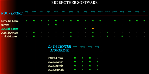
Remote Monitoring (RMON) is a network-monitoring tool supported by a series of probes. RMON enables network administrators to monitor and analyze devices such as routers and switches on a LAN. The type of information RMON probes return includes items such as errors, packet statistics, bandwidth data, and device statistics.
Risks to Network Infrastructure and Controls
One key task for the auditor is to assess the network infrastructure for potential threats. The auditor should assess existing controls to evaluate their effectiveness at minimizing risks. Table 6.10 lists some of the physical controls that should be verified. Table 6.11 lists some of the logical controls that should be verified.
Table 6.10 Auditing Physical Network Controls
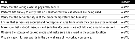
Table 6.11 Auditing Logical Network Controls
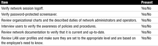
Chapter Summary
This chapter reviewed the systems used for IT delivery and support. To better understand these systems, we reviewed concepts such as the OSI model, a seven-layer model that defines networking in a layered fashion. Although the OSI model is widely used for teaching, the system most associated with networking today is TCP/IP, a four-layer model that combines some of the layers found in the OSI model. The TCP/IP model is based on protocols such as IP, a routable protocol used to carry high-layer headers and data. IP commonly carries TCP or UDP. TCP is a connection-oriented protocol used for reliability. UDP is a connectionless protocol used for speed. TCP carries applications such as HTTP and FTP. UDP carries applications such as DHCP, TFTP, and DNS queries.
An IS auditor is expected to understand this technology and know how the various pieces of networking equipment work. The CISA should look closely at the technology the organization uses and examine its controls and potential vulnerabilities. Technology is a great benefit, but without proper controls, it can present many dangers.
Key Terms
![]() Address Resolution Protocol (ARP)
Address Resolution Protocol (ARP)
![]() Asynchronous Transfer Mode (ATM)
Asynchronous Transfer Mode (ATM)
![]() Carrier Sense Multiple Access/Collision Detection (CSMA/CD)
Carrier Sense Multiple Access/Collision Detection (CSMA/CD)
![]() Circuit switching
Circuit switching
![]() Collision domain
Collision domain
![]() Collisions
Collisions
![]() Committed information rate (CIR)
Committed information rate (CIR)
![]() Common Gateway Interface (CGI)
Common Gateway Interface (CGI)
![]() Cookies
Cookies
![]() Direct-sequence spread spectrum (DSS)
Direct-sequence spread spectrum (DSS)
![]() Discovery, offer, request, acceptance (DORA)
Discovery, offer, request, acceptance (DORA)
![]() Domain name server (DNS)
Domain name server (DNS)
![]() Domain Name Service (DNS)
Domain Name Service (DNS)
![]() Dual-homed gateway
Dual-homed gateway
![]() Dwell time
Dwell time
![]() Dynamic Host Configuration Protocol (DHCP)
Dynamic Host Configuration Protocol (DHCP)
![]() File Transfer Protocol (FTP)
File Transfer Protocol (FTP)
![]() Frequency-hopping spread spectrum (FHSS)
Frequency-hopping spread spectrum (FHSS)
![]() Fully qualified domain names (FQDN)
Fully qualified domain names (FQDN)
![]() Gigabit Ethernet
Gigabit Ethernet
![]() Hypertext Markup Language (HTML)
Hypertext Markup Language (HTML)
![]() Hypertext Transfer Protocol (HTTP)
Hypertext Transfer Protocol (HTTP)
![]() Integrated Services Digital Network (ISDN)
Integrated Services Digital Network (ISDN)
![]() Internet service provider (ISP)
Internet service provider (ISP)
![]() Layer 2 bridge
Layer 2 bridge
![]() Layer 2 switch
Layer 2 switch
![]() Management information base (MIB)
Management information base (MIB)
![]() Mesh topology
Mesh topology
![]() Metropolitan area network (MAN)
Metropolitan area network (MAN)
![]() Multiprotocol Label Switching (MPLS)
Multiprotocol Label Switching (MPLS)
![]() National access point
National access point
![]() National service providers (NSP)
National service providers (NSP)
![]() Open Shortest Path First (OSPF)
Open Shortest Path First (OSPF)
![]() Orthogonal frequency-division multiplexing (OFDM)
Orthogonal frequency-division multiplexing (OFDM)
![]() Plain old telephone service (POTS)
Plain old telephone service (POTS)
![]() Point-to-Point Tunneling Protocol (PPTP)
Point-to-Point Tunneling Protocol (PPTP)
![]() Routing Information Protocol (RIP)
Routing Information Protocol (RIP)
![]() Screen host firewall
Screen host firewall
![]() Screened host
Screened host
![]() Screened subnet
Screened subnet
![]() Simple Mail Transfer Protocol (SMTP)
Simple Mail Transfer Protocol (SMTP)
![]() Simple Network Management Protocol (SNMP)
Simple Network Management Protocol (SNMP)
![]() Spreading code
Spreading code
![]() Star topology
Star topology
![]() Terminal-emulation software (TES)
Terminal-emulation software (TES)
![]() Transmission Control Protocol (TCP)
Transmission Control Protocol (TCP)
![]() Twisted-pair cable
Twisted-pair cable
![]() Unicast
Unicast
![]() Uniform resource locator (URL)
Uniform resource locator (URL)
![]() Virtual LAN (VLAN)
Virtual LAN (VLAN)
![]() Voice over IP (VoIP)
Voice over IP (VoIP)
![]() WiFi Protected Access (WPA)
WiFi Protected Access (WPA)
![]() Wired Equivalent Privacy (WEP)
Wired Equivalent Privacy (WEP)
![]() Wireless access point (wireless AP)
Wireless access point (wireless AP)
![]() Wireless PAN (WPAN)
Wireless PAN (WPAN)
Apply Your Knowledge
This chapter has reviewed many aspects of logical security and discussed how computer networks operate.
In this exercise, you examine the TCP/IP model, identify OSI model components, and describe common firewall characteristics.
Exercises
6.1 Identifying TCP/IP Components
Estimated Time: 10 minutes
1. Using Figure 6.12 and your knowledge of TCP/IP, determine what LAN protocol is being used.
________________________________
Figure 6.12 Network analyzer capture.

2. Refer to Figure 6.12 and identify the proper transport protocol.
3. Referring to Figure 6.12, what application-layer protocol is in use?
You should have answered 1-Ethernet, 2-TCP, and 3-HTTP.
4. Place the following items into the proper layers of the OSI model: MAC addresses, ASCII, TCP, IP, and HTTP.
__________ Application
__________ Presentation
__________ Session
__________ Transport
__________ Network
__________ Data link
__________ Physical
5. Place the following pieces of equipment into the proper layer of the OSI model: fiber, routers, hubs, switches, bridges, packet filters, application proxy firewall.
__________ Application
__________ Presentation
__________ Session
__________ Transport
__________ Network
__________ Data link
__________ Physical
Answers to questions 4 and 5 are as follows:
Application—HTTP, application proxy firewall
Presentation—ASCII
Session
Transport—TCP
Network—IP, routers, packet filters
Data link—MAC addresses, switches, bridges
Physical—Fiber, hubs
Exam Questions
1. Which of the following is the best example of a method to measure latency?
![]() A. SNMP management tool
A. SNMP management tool
![]() B.
B. ping command
![]() C. traceroute
C. traceroute
![]() D. RMON
D. RMON
2. Which of the following is the proper order for the OSI model from the bottom up?
![]() A. Data link, media access, network, transport, session, presentation, application
A. Data link, media access, network, transport, session, presentation, application
![]() B. Physical, data link, network, transport, session, presentation, application
B. Physical, data link, network, transport, session, presentation, application
![]() C. Physical, data link, network, transport, presentation, session, application
C. Physical, data link, network, transport, presentation, session, application
![]() D. Data link, physical link, network, transport, presentation, session, application
D. Data link, physical link, network, transport, presentation, session, application
3. Which type of data transmission is to a group of devices on a LAN?
![]() A. Unicast
A. Unicast
![]() B. Multicast
B. Multicast
![]() C. Anycast
C. Anycast
![]() D. Broadcast
D. Broadcast
4. Which of the following is the best explanation of ARP?
![]() A. ARP resolves known domain names to unknown IP addresses.
A. ARP resolves known domain names to unknown IP addresses.
![]() B. ARP resolves known IP addresses to unknown MAC addresses.
B. ARP resolves known IP addresses to unknown MAC addresses.
![]() C. ARP resolves known IP addresses to unknown domain names.
C. ARP resolves known IP addresses to unknown domain names.
![]() D. ARP resolves known MAC addresses to unknown IP addresses.
D. ARP resolves known MAC addresses to unknown IP addresses.
5. Which of the following best matches the description of a packet-switching technology with a committed information rate?
![]() A. T1
A. T1
![]() B. ATM
B. ATM
![]() C. X.25
C. X.25
![]() D. Frame Relay
D. Frame Relay
6. Which of the following is a fiber-optic cable standard?
![]() A. 1000BASE-TX
A. 1000BASE-TX
![]() B. 1000BASE-LX
B. 1000BASE-LX
![]() C. 10BASE-T
C. 10BASE-T
![]() D. 100BASE-TX
D. 100BASE-TX
7. An auditor has been asked to perform a network audit. Which of the following is the best place for the auditor to start?
![]() A. Review help-desk report
A. Review help-desk report
![]() B. Review database architecture
B. Review database architecture
![]() C. Interview users
C. Interview users
![]() D. Review network diagrams
D. Review network diagrams
8. Which of the following network designs offers the highest level of redundancy?
![]() A. Bus
A. Bus
![]() B. Star
B. Star
![]() C. Ring
C. Ring
![]() D. Mesh
D. Mesh
9. Which of the following devices would best be suited for reducing the number of collisions on a LAN?
![]() A. Switch
A. Switch
![]() B. Hub
B. Hub
![]() C. Bridge
C. Bridge
![]() D. Router
D. Router
10. Which of the following statements best describes packet switching?
![]() A. Packet switching allows the customer to determine the best path.
A. Packet switching allows the customer to determine the best path.
![]() B. Packet switching takes a dedicated path established by the vendor.
B. Packet switching takes a dedicated path established by the vendor.
![]() C. Packet switching allows the vendor to determine the best path.
C. Packet switching allows the vendor to determine the best path.
![]() D. Packet switching takes a dedicated path established by the client.
D. Packet switching takes a dedicated path established by the client.
Answers to Exam Questions
1. B. Latency can be caused because data must travel great distances or because of high volumes of network traffic and inadequate bandwidth. Latency can be measured with the ping command. Answer A is incorrect because SNMP is used for network management. Answer C is incorrect because traceroute is used to determine the path that traffic takes from one network to another. Answer D is incorrect because RMON is another example of a network-management tool.
2. B. The proper order for the OSI model from the bottom up is physical, data link, network, transport, session, presentation, application. Therefore, answers A, C, and D are incorrect.
3. B. Network traffic on a LAN can be addressed to one device, many devices, or all devices on the network. Sending information to a group is known as a multicast. Answer A describes one device; answer C describes a technique used in IPv6, which is a directed broadcast; and answer D describes the transmission to everyone.
4. B. ARP resolves known IP addresses to unknown MAC addresses. This two-step process is performed by first sending a message to all devices on the LAN requesting the receiver’s physical address. If a device recognizes the address as its own, it issues an ARP reply to the sender of the ARP request. Answers A, C, and D are incorrect because they do not properly describe the ARP process.
5. D. Frame Relay controls bandwidth usage with a committed information rate (CIR) that specifies the maximum guaranteed bandwidth that the customer is guaranteed. Although higher rates might be possible, the CIR represents the level the service provider is committed to providing. Answer A, T1, does not use a CIR and is not packet switching. Answer B, ATM, does not use a CIR. Answer C, X.25, does not use a CIR.
6. B. Some of the standards for optical fiber cabling include 10BASE-F, 100BASE-FX, and 1000BASE-LX. Answers A, C, and D are all copper cabling standards.
7. D. Reviewing network diagrams is usually the best place for the auditor to start. This gives the auditor a foundational understanding of the network. Although answers A, B, and C are all items that can be performed, they should not be the starting point of the audit.
8. D. A mesh offers the highest level of redundancy. Answers A, B, and C are incorrect.
9. A. A switch is best suited for reducing the number of collisions on a LAN. Switches segment physical networks. Answer B is incorrect because a hub provides only physical connectivity. Answer C is incorrect because a bridge is inferior to a switch. Bridges are software based and are much slower. Answer D is incorrect because a router is an OSI Layer 3 device.
10. C. Packet switching allows the telecommunication’s vendor to determine the best path. The vendor is free to route the packetized traffic through the network as it sees fit. Answer A is incorrect because the customer does not determine the path. Answer B is incorrect because packet switching does not use a dedicated path. Answer D is incorrect because the client does not set a dedicated path for packet-switched traffic.
Need to Know More?
![]() A Beginner’s Guide to Wireless Security: http://www.pcstats.com/articleview.cfm?articleID=1489
A Beginner’s Guide to Wireless Security: http://www.pcstats.com/articleview.cfm?articleID=1489
![]() A Guide to Understanding Firewalls: http://www.hslanj.org/Ambrose.pps
A Guide to Understanding Firewalls: http://www.hslanj.org/Ambrose.pps
![]() An Introduction to Internet Firewalls: http://csrc.nist.gov/publications/nistpubs/
An Introduction to Internet Firewalls: http://csrc.nist.gov/publications/nistpubs/
![]() The OSI Model: http://en.wikipedia.org/wiki/OSI_model
The OSI Model: http://en.wikipedia.org/wiki/OSI_model
![]() Understanding TCP/IP: http://www.cisco.com/univercd/cc/td/doc/product/iaabu/centri4/user/scf4ap1.htm
Understanding TCP/IP: http://www.cisco.com/univercd/cc/td/doc/product/iaabu/centri4/user/scf4ap1.htm
![]() Network Cabling Basics: http://www.datacottage.com/nch/basics.htm
Network Cabling Basics: http://www.datacottage.com/nch/basics.htm
![]() A Quick Guide to Common Attacks: http://www.windowsecurity.com/articles/Common_Attacks.html
A Quick Guide to Common Attacks: http://www.windowsecurity.com/articles/Common_Attacks.html
![]() The History of the Internet: http://www.elsop.com/wrc/h_web.htm
The History of the Internet: http://www.elsop.com/wrc/h_web.htm
![]() Cookies, the Hidden Truth: http://www.cookiecentral.com/
Cookies, the Hidden Truth: http://www.cookiecentral.com/