Chapter 4
Communication and Network Security
This chapter covers the following topics:
Secure Network Design Principles: Concepts covered include the OSI and TCP/IP models.
IP Networking: Concepts discussed include common TCP/UDP ports, logical and physical addressing, network transmission, and network types.
Protocols and Services: Protocols and services discussed include ARP, DHCP, DNS, FTP, HTTP, ICMP, IMAP, LDAP, NAT, NetBIOS, NFS, PAT, POP, CIFS/SMB, SMTP, SNMP, and multilayer protocols.
Converged Protocols: Protocols discussed include FCoE, MPLS, VoIP, and iSCSI.
Wireless Networks: Concepts covered include wireless techniques, WLAN structure, WLAN standards, and WLAN security.
Communications Cryptography: Concepts discussed include link encryption, end-to-end encryption, email security, and Internet security.
Secure Network Components: Components discussed include operation of hardware, transmission media, network access control devices, endpoint security, and content-distribution networks.
Secure Communication Channels: Topics discussed include voice, multimedia collaboration, remote access, data communications, and virtualized networks.
Network Attacks: Concepts discussed include cabling attacks, network component attacks, ICMP attacks, DNS attacks, email attacks, wireless attacks, remote attacks, and other attacks.
Sensitive data must be protected from unauthorized access when the data is at rest (on a hard drive) and in transit (moving through a network). Moreover, sensitive communications of other types such as emails, instant messages, and phone conversations must also be protected from prying eyes and ears. Many communication processes send information in a form that can be read and understood if captured with a protocol analyzer or sniffer.
The Communication and Network Security domain addresses a broad array of topics including network architecture, components, and secure communication channels. Out of 100% of the exam, this domain carries an average weight of 14%, which is the second highest weight of all the eight domains. So, pay close attention to the many details in this chapter!
In the world of communication today, you should assume that your communications are being captured regardless of how unlikely you think that might be. You should also take steps to protect or encrypt the transmissions so they will be useless to anyone capturing them. This chapter covers the protection of wired and wireless transmissions and of the network devices that perform the transmissions, as well as some networking fundamentals required to understand transmission security.
Foundation Topics
Secure Network Design Principles
To properly configure communication and network security, security professionals must understand secure network design principles. They need to know how to ensure that a network is set up properly and will need minimal reconfiguration in the future. To use secure network design principles, security professionals must understand the OSI and TCP/IP models.
OSI Model
A complete understanding of networking requires an understanding of the Open Systems Interconnection (OSI) model. Created in the 1980s by the International Organization for Standardization (ISO) as a part of its mission to create a protocol set to be used as a standard for all vendors, the OSI model breaks the communication process into layers. Although the ensuing protocol set did not catch on as a standard (Transmission Control Protocol/Internet Protocol [TCP/IP] was adopted), the model has guided the development of technology since its creation. It also has helped generations of students understand the network communication process between two systems.
The OSI model breaks up the process into seven layers, or modules. The benefits of doing this are
It breaks up the communication process into layers with standardized interfaces between the layers, allowing for changes and improvements on one layer without necessitating changes on other layers.
It provides a common framework for hardware and software developers, fostering interoperability.
This open systems architecture is owned by no vendor, and it acts as a blueprint or model for developers to work with. Various protocols operate at different layers of this model. A protocol is a set of communication rules two systems must both use and understand to communicate. Some protocols depend on other protocols for services, and as such, these protocols work as a team to get transmissions done, much like the team at the post office that gets your letters delivered. Some people sort, others deliver, and still others track lost shipments.
The OSI model and the TCP/IP model, explained in the next section, are often both used to describe the process called packet creation, or encapsulation. Until a packet is created to hold the data, it cannot be sent on the transmission medium.
With a modular approach, it is possible for a change in a protocol or the addition of a new protocol to be accomplished without having to rewrite the entire protocol stack (a term for all the protocols that work together at all layers). The model has seven layers. This section discusses each layer’s function and its relationship to the layer above and below it in the model. The layers are often referred to by their number with the numbering starting at the bottom of the model at Layer 1, the Physical layer.
The process of creating a packet or encapsulation begins at Layer 7, the Application layer rather than Layer 1, so we discuss the process starting at Layer 7 and work down the model to Layer 1, the Physical layer, where the packet is sent out on the transmission medium.
Application Layer
The Application layer (Layer 7) is where the encapsulation process begins. This layer receives the raw data from the application in use and provides services, such as file transfer and message exchange to the application (and thus the user). An example of a protocol that operates at this layer is Hypertext Transfer Protocol (HTTP), which is used to transfer web pages across the network. Other examples of protocols that operate at this layer are DNS queries, FTP transfers, and SMTP email transfers. The Dynamic Host Configuration Protocol (DHCP) and DHCP for IPv6 (DHCPv6) also operate at this layer.
The user application interfaces with these application protocols through a standard interface called an application programming interface (API). The Application layer protocol receives the raw data and places it in a container called a protocol data unit (PDU). When the process gets down to Layer 4, these PDUs have standard names, but at Layers 5–7 we simply refer to the PDU as “data.”
Presentation Layer
The information that is developed at Layer 7 is then handed to Layer 6, the Presentation layer. Each layer makes no changes to the data received from the layer above it. It simply adds information to the developing packet. In the case of the Presentation layer, information is added that standardizes the formatting of the information if required.
Layer 6 is responsible for the manner in which the data from the Application layer is represented (or presented) to the Application layer on the destination device (explained more fully in the section “Encapsulation and De-encapsulation”). If any translation between formats is required, it will take care of it. It also communicates the type of data within the packet and the application that might be required to read it on the destination device.
This layer consists of two sublayers: the common application service element (CASE) sublayer and the specific application service element (SASE) sublayer. CASE provides services to the Application layer and requests services from the Session layer. SASE supports application-specific services.
Session Layer
The Session layer, or Layer 5, is responsible for adding information to the packet that makes a communication session between a service or application on the source device possible with the same service or application on the destination device. Do not confuse this process with the one that establishes a session between the two physical devices. That occurs not at this layer but at Layers 3 and 4. This session is built and closed after the physical session between the computers has taken place.
The application or service in use is communicated between the two systems with an identifier called a port number. This information is passed on to the Transport layer, which also makes use of these port numbers.
Transport Layer
The protocols that operate at the Transport layer (Layer 4) work to establish a session between the two physical systems. The service provided can be either connection-oriented or connectionless, depending on the transport protocol in use. The “TCP/IP Model” section (TCP/IP being the most common standard networking protocol suite in use) discusses the specific transport protocols used by TCP/IP in detail.
The Transport layer receives all the information from Layers 7, 6, and 5 and adds information that identifies the transport protocol in use and the specific port number that identifies the required Layer 7 protocol. At this layer, the PDU is called a segment because this layer takes a large transmission and segments it into smaller pieces for more efficient transmission on the medium.
Network Layer
At Layer 3, or the Network layer, information required to route the packet is added. This is in the form of a source and destination logical address (meaning one that is assigned to a device in some manner and can be changed). In TCP/IP, this is in terms of a source and destination IP address. An IP address is a number that uniquely differentiates a host from all other devices on the network. It is based on a numbering system that makes it possible for computers (and routers) to identify whether the destination device is on the local network or on a remote network. Any time a packet needs to be sent to a different network or subnet (IP addressing is covered later in the chapter), it must be routed and the information required to do that is added here. At this layer, the PDU is called a packet.
Data Link Layer
The Data Link layer, or Layer 2, is responsible for determining the destination physical address. Network devices have logical addresses (IP addresses) and the network interfaces they possess have a physical address (a media access control [MAC] address), which is permanent in nature. When the transmission is handed off from routing device to routing device, at each stop this source and destination address pair changes, whereas the source and destination logical addresses (in most cases IP addresses) do not. This layer is responsible for determining what those MAC addresses should be at each hop (router interface) and adding them to this part of the packet. The later section “TCP/IP Model” covers how this resolution is performed in TCP/IP. After this is done, we call the PDU a frame.
In some networks, the Data Link layer is discussed as including the media access control (MAC) and logical link control (LLC) sublayers. In the Data Link layer, the IEEE 802.2 LLC protocol can be used with all of the IEEE 802 MAC layers.
Something else happens that is unique to this layer. Not only is a Layer 2 header placed on the packet but also a trailer at the “end” of the frame. Information contained in the trailer is used to verify that none of the data contained has been altered or damaged en route.
Physical Layer
Finally, the packet (or frame, as it is called at Layer 2) is received by the Physical layer (Layer 1). Layer 1 is responsible for turning the information into bits (ones and zeros) and sending it out on the medium. The way in which this is accomplished can vary according to the media in use. For example, in a wired network, the ones and zeros are represented as electrical charges. In wireless, they are represented by altering the radio waves. In an optical network, they are represented with light.
The ability of the same packet to be routed through various media types is a good example of the independence of the layers. As a PDU travels through different media types, the physical layer will change but all the information in Layers 2–7 will not. Similarly, when a frame crosses routers or hops, the MAC addresses change but none of the information in Layers 3–7 changes. The upper layers depend on the lower layers for various services, but the lower layers leave the upper layer information unchanged.
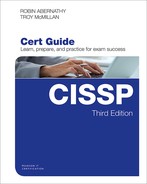
Figure 4-1 shows common protocols mapped to the OSI model. The next section covers another model that perhaps more accurately depicts what happens in a TCP/IP network. Because TCP/IP is the standard now for transmission, comparing these two models is useful. Although they have a different number of layers and some of the layer names are different, they describe the same process of packet creation or encapsulation.


TCP/IP Model
The protocols developed when the OSI model was developed (sometimes referred to as OSI protocols) did not become the standard for the Internet. The Internet as we know it today has its roots in a wide area network (WAN) developed by the Department of Defense (DoD), with TCP/IP being the protocol developed for that network. The Internet is a global network of public networks and Internet service providers (ISPs) throughout the world.
This model bears many similarities to the OSI model, which is not unexpected because they both describe the process of packet creation or encapsulation. The difference is that the OSI model breaks the process into seven layers, whereas the TCP/IP model breaks it into four. If you examine them side by side, however, it becomes apparent that many of the same functions occur at the same layers, while the TCP/IP model combines the top three layers of the OSI model into one and the bottom two layers of the OSI model into one. Figure 4-2 shows the two models next to one another.
The TCP/IP model has only four layers and is useful to study because it focuses its attention on TCP/IP. This section explores those four layers and their functions and relationships to one another and to layers in the OSI model.
Application Layer
Although the Application layer in the TCP/IP model has the same name as the top layer in the OSI model, the Application layer in the TCP/IP model encompasses all the functions performed in Layers 5–7 in the OSI model. Not all functions map perfectly because both are simply conceptual models. Within the Application layer, applications create user data and communicate this data to other processes or applications on another host. For this reason, it is sometimes also referred to as the process-to-process layer.
Examples of protocols that operate at this layer are SMTP, FTP, SSH, and HTTP. These protocols are discussed in the section “Protocols and Services,” later in this chapter. In general, however, these are usually referred to as higher layer protocols that perform some specific function, whereas protocols in the TCP/IP suite that operate at the Transport and Internet layers perform location and delivery service on behalf of these higher layer protocols.
A port number identifies to the receiving device these upper layer protocols and the programs on whose behalf they function. The number identifies the protocol or service. Many port numbers have been standardized. For example, Domain Name System (DNS) is identified with the standard port number 53. The “Common TCP/UDP Ports” section covers these port numbers in more detail.
Transport Layer
The Transport layers of the OSI model and the TCP/IP model perform the same function, which is to open and maintain a connection between hosts. This must occur before the session between the processes can occur as described in the Application layer section and can be done in TCP/IP in two ways: connectionless and connection-oriented. A connection-oriented transmission means that a connection will be established before any data is transferred, whereas in a connectionless transmission this is not done. One of two different transport layer protocols is used for each process. If a connection-oriented transport protocol is required, Transmission Control Protocol (TCP) will be used. If the process will be connectionless, User Datagram Protocol (UDP) is used.
Application developers can choose to use either TCP or UDP as the Transport layer protocol used with the application. Regardless of which transport protocol is used, the application or service will be identified to the receiving device by its port number and the transport protocol (UDP or TCP).
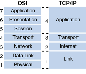
Although TCP provides more functionality and reliability, the overhead required by this protocol is substantial when compared to UDP. This means that a much higher percentage of the packet consists of the header when using TCP than when using UDP. This is necessary to provide the fields required to hold the information needed to provide the additional services. Figure 4-3 shows a comparison of the sizes of the two respective headers.
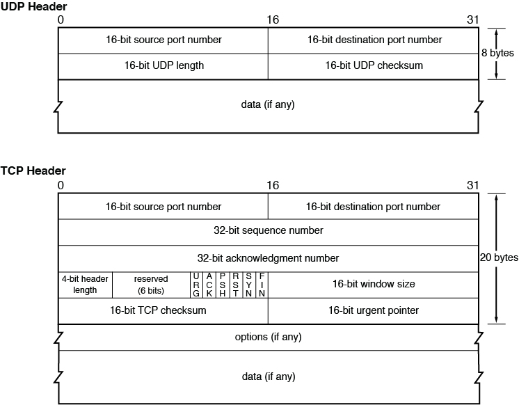
When an application is written to use TCP, a state of connection is established between the two hosts before any data is transferred. This occurs using a process known as the TCP three-way handshake. This process is followed exactly, and no data is transferred until it is complete. Figure 4-4 shows the steps in this process. The steps are as follows:
The initiating computer sends a packet with the SYN flag set (one of the fields in the TCP header), which indicates a desire to create a connection.
The receiving host acknowledges receiving this packet and indicates a willingness to create a state of connection by sending back a packet with both the SYN and ACK flags set.
The first host acknowledges completion of the connection process by sending a final packet back with only the ACK flag set.
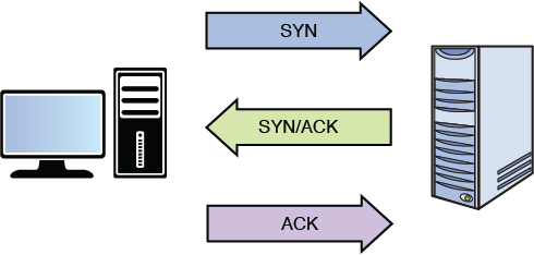
Figure 4-4 TCP Three-Way Handshake
So what exactly is gained by using the extra overhead to use TCP? The following are examples of the functionality provided with TCP:
Guaranteed delivery: If the receiving host does not specifically acknowledge receipt of each packet, the sending system will resend the packet.
Sequencing: In today’s routed networks, the packets might take many different routes to arrive and might not arrive in the order in which they were sent. A sequence number added to each packet allows the receiving host to reassemble the entire transmission using these numbers.
Flow control: The receiving host has the capability of sending the acknowledgement packets back to signal the sender to slow the transmission if it cannot process the packets as fast as they are arriving.
Many applications do not require the services provided by TCP or cannot tolerate the overhead required by TCP. In these cases the process will use UDP, which sends on a “best effort” basis with no guarantee of delivery. In many cases some of these functions are provided by the Application layer protocol itself rather than relying on the Transport layer protocol.
Internet Layer
The Transport layer can neither create a state of connection nor send using UDP until the location and route to the destination are determined, which occurs on the Internet layer. The four protocols in the TCP/IP suite that operate at this layer are
Internet Protocol (IP): Responsible for putting the source and destination IP addresses in the packet and for routing the packet to its destination.
Internet Control Message Protocol (ICMP): Used by the network devices to send messages regarding the success or failure of communications and used by humans for troubleshooting. When you use the ping or traceroute/tracert commands, you are using ICMP.
Internet Group Management Protocol (IGMP): Used when multicasting, which is a form of communication whereby one host sends to a group of destination hosts rather than a single host (called a unicast transmission) or to all hosts (called a broadcast transmission). There are three versions of IGMP. Version 2 adds two query types: general query and group-specific query. Version 3 adds membership query.
Address Resolution Protocol (ARP): Resolves the IP address placed in the packet to a physical address (called a MAC address in Ethernet).
The relationship between IP and ARP is worthy of more discussion. IP places the source and destination IP addresses in the header of the packet. As we saw earlier, when a packet is being routed across a network, the source and destination IP addresses never change but the Layer 2 or MAC address pairs change at every router hop. ARP uses a process called the ARP broadcast to learn the MAC address of the interface that matches the IP address of the next hop. After it has done this, a new Layer 2 header is created. Again, nothing else in the upper layer changes in this process, just Layer 2.
That brings up a good point concerning the mapping of ARP to the TCP/IP model. Although we generally place ARP on the Internet layer, the information it derives from this process is placed in the Link layer or Layer 2, the next layer in our discussion.
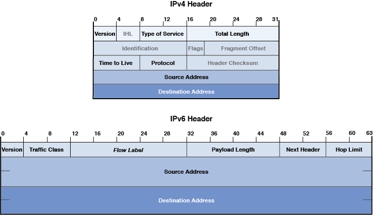
Just as the Transport layer added a header to the packet, so does the Internet layer. One of the improvements made by IPv6 is the streamlining of the IP header. Although the same information is contained in the header and the header is larger, it has a much simpler structure. Figure 4-5 shows a comparison of the two.
Link Layer
The Link layer, also called Network Access layer, of the TCP/IP model provides the services provided by both the Data Link and the Physical layers in the OSI model. The source and destination MAC addresses are placed in this layer’s header. A trailer is also placed on the packet at this layer with information in the trailer that can be used to verify the integrity of the data.
This layer is also concerned with placing the bits on the medium, as discussed in the section “OSI Model,” earlier in this chapter. Again, the exact method of implementation varies with the physical transmission medium. It might be in terms of electrical impulses, light waves, or radio waves.
Encapsulation and De-encapsulation
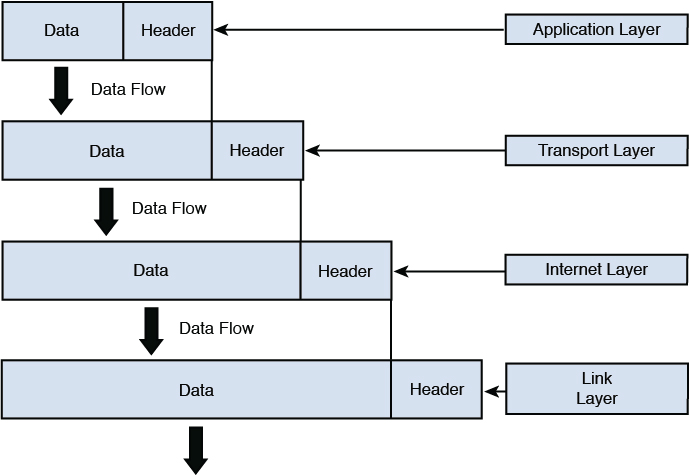
In either model as the packet is created, information is added to the header at each layer and then a trailer is placed on the packet before transmission. This process is called encapsulation. Intermediate devices, such as routers and switches, only read the layers of concern to that device (for a switch, Layer 2 and for a router, Layer 3). The ultimate receiver strips off the entire header with each layer, making use of the information placed in the header by the corresponding layer on the sending device. This process is called de-encapsulation. Figure 4-6 shows a visual representation of encapsulation.
IP Networking
Now that you understand secure design principles and the OSI and TCP/IP models, it is time to delve more deeply into IP networking. The Internet Protocol (IP) is the main communications protocol in the TCP/IP suite and is responsible for relaying datagrams across network boundaries. This section covers common TCP/UDP ports, logical and physical addressing, network transmission, and network types.
Common TCP/UDP Ports
When the Transport layer learns the required port number for the service or application required on the destination device from the Application layer, it is recorded in the header as either a TCP or UDP port number. Both UDP and TCP use 16 bits in the header to identify these ports. These port numbers are software based or logical, and there are 65,535 possible numbers. Port numbers are assigned in various ways, based on three ranges:
System, or well-known, ports (0–1023)
User ports (1024–49151)
Dynamic and/or private ports (49152–65535)
System ports are assigned by the Internet Engineering Task Force (IETF) for standards-track protocols, as per RFC 6335. User ports can be registered with the Internet Assigned Numbers Authority (IANA) and assigned to the service or application using the “Expert Review” process, as per RFC 6335. Dynamic ports are used by source devices as source ports when accessing a service or application on another machine. For example, if computer A is sending an FTP packet, the destination port will be the well-known port for FTP and the source will be selected by the computer randomly from the dynamic range.
The combination of the destination IP address and the destination port number is called a socket. The relationship between these two values can be understood if viewed through the analogy of an office address. The office has a street address, but the address also must contain a suite number as there could be thousands (in this case 65,535) of suites in the building. Both are required to get the information where it should go.
As a security professional, you should be aware of well-known port numbers of common services. In many instances, firewall rules and access control lists (ACLs) are written or configured in terms of the port number of what is being allowed or denied rather than the name of the service or application. Table 4-1 lists some of the more important port numbers. Some use more than one port.
Table 4-1 Common TCP/UDP Port Numbers
Application Protocol |
Transport Protocol |
Port Number |
|---|---|---|
Telnet |
TCP |
23 |
SMTP |
UDP |
25 |
HTTP |
TCP |
80 |
SNMP |
TCP and UDP |
161 and 162 |
FTP |
TCP and UDP |
20 and 21 |
FTPS |
TCP |
989 and 990 |
SFTP |
TCP |
22 |
TFTP |
UDP |
69 |
POP3 |
TCP and UDP |
110 |
DNS |
TCP and UDP |
53 |
DHCP |
UDP |
67 and 68 |
SSH |
TCP |
22 |
LDAP |
TCP and UDP |
389 |
NetBIOS |
TCP and UDP |
137 (TCP), 138 (TCP), and 139 (UDP) |
CIFS/SMB |
TCP |
445 |
NFSv4 |
TCP |
2049 |
SIP |
TCP and UDP |
5060 |
XMPP |
TCP |
5222 |
IRC |
TCP and UDP |
194 |
RADIUS |
TCP and UDP |
1812 and 1813 |
rlogin |
TCP |
513 |
rsh and RCP |
TCP |
514 |
IMAP |
TCP |
143 |
HTTPS |
TCP and UDP |
443 |
RDP |
TCP and UDP |
3389 |
AFP over TCP |
TCP |
548 |
Logical and Physical Addressing
During the process of encapsulation at Layer 3 of the OSI model, IP places source and destination IP addresses in the packet. Then at Layer 2, the matching source and destination MAC addresses that have been determined by ARP are placed in the packet. IP addresses are examples of logical addressing, and MAC addresses are examples of physical addressing. IP addresses are considered logical because these addresses are administered by humans and can be changed at any time. MAC addresses on the other hand are assigned permanently to the interface cards of the devices when the interfaces are manufactured. It is important to note, however, that although these addresses are permanent, they can be spoofed. When this is done, however, the hacker is not actually changing the physical address but rather telling the interface to place a different MAC address in the Layer 2 headers.
This section discusses both address types with a particular focus on how IP addresses are used to create separate networks or subnets in the larger network. It also discusses how IP addresses and MAC addresses are related and used during a network transmission.
IPv4
IPv4 addresses are 32 bits in length and can be represented in either binary or in dotted-decimal format. The number of possible IP addresses using 32 bits can be calculated by raising the number 2 (the number of possible values in the binary number system) to the 32nd power. The result is 4,294,967,296, which on the surface appears to be enough IP addresses. But with the explosion of the Internet and the increasing number of devices that require an IP address, this number has proven to be insufficient.
Due to the eventual exhaustion of the IPv4 address space, several methods of preserving public IP addresses (more on that in a bit, but for now these are addresses that are legal to use on the Internet) have been implemented, including the use of private addresses and network address translation (NAT), both discussed in the following sections. The ultimate solution lies in the adoption of IPv6, a newer system that uses 128 bits and allows for enough IP addresses for each man, woman, and child on the planet to have as many IP addresses as the entire IPv4 numbering space. IPv6 is discussed later in this section.
IP addresses that are written in dotted-decimal format, the format in which humans usually work with them, have four fields called octets separated by dots or periods. Each field is called an octet because when we look at the addresses in binary format, we devote 8 bits in binary to represent each decimal number that appears in the octet when viewed in dotted-decimal format. Therefore, if we look at the address 216.5.41.3, four decimal numbers are separated by dots, where each would be represented by 8 bits if viewed in binary. The following is the binary version of this same address:
11011000.00000101.00101001.00000011
There are 32 bits in the address, 8 in each octet.
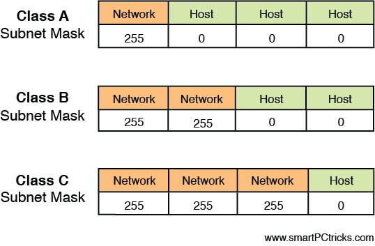
The structure of IPv4 addressing lends itself to dividing the network into subdivisions called subnets. Each IP address also has a required companion value called a subnet mask. The subnet mask is used to specify which part of the address is the network part and which part is the host. The network part, on the left side of the address, determines on which network the device resides, whereas the host portion on the right identifies the device on that network. Figure 4-7 shows the network and host portions of the three default classes of IP address.
When the IPv4 system was first created, there were only three default subnet masks. This yielded only three sizes of networks, which later proved to be inconvenient and wasteful of public IP addresses. Eventually a system called Classless Inter-Domain Routing (CIDR) was adopted that uses subnet masks that allow you to make subnets or subdivisions out of the major classful networks possible before CIDR. CIDR is beyond the scope of the exam but it is worth knowing about. You can find more information about how CIDR works at https://searchnetworking.techtarget.com/definition/CIDR.
IP Classes
Classful subnetting (pre-CIDR) created five classes of networks. Each class represented a range of IP addresses. Table 4-2 shows the five classes. Only the first three (A, B, and C) are used for individual network devices. The other ranges are for special use.
Table 4-2 Classful IP Addressing
Class |
Range |
Mask |
Initial Bit Pattern of First Octet |
Network/Host Division |
|---|---|---|---|---|
Class A |
0.0.0.0–127.255.255.255 |
255.0.0.0 |
01 |
net.host.host.host |
Class B |
128.0.0.0–191.255.255.255 |
255.255.0.0 |
10 |
net.net.host.host |
Class C |
192.0.0.0–223.255.255.255 |
255.255.255.0 |
11 |
net.net.net.host |
Class D |
224.0.0.0–239.255.255.255 |
Used for multicasting |
|
|
Class E |
240.0.0.0–255.255.255.255 |
Reserved for research |
|
|
As you can see, the key value that changes as you move from one class to another is the value of the first octet (the one on the far left). What might not be immediately obvious is that as you move from one class to another, the dividing line between the host portion and network portion also changes. This is where the subnet mask value comes in. When the mask is overlaid with the IP addresses (thus we call it a mask), every octet in the subnet mask where there is a 255 is a network portion and every octet where there is a 0 is a host portion. Another item to mention is that each class has a distinctive pattern in the first two bits of the first octet. For example, any IP address that begins with 01 in the first bit positions must be in Class A, also indicated in Table 4-2.
The significance of the network portion is that two devices must share the same values in the network portion to be in the same network. If they do not, they will not be able to communicate.
Public Versus Private IP Addresses
The initial solution used (and still in use) to address the exhaustion of the IPv4 space involved the use of private addresses and NAT. Three ranges of IP addresses were set aside to be used only within private networks and are not routable on the Internet. RFC 1918 set aside the private IP address ranges in Table 4-3 to be used for this purpose. Because these addresses are not routable on the public network, they must be translated to public addresses before being sent to the Internet. This process, called NAT, is discussed in the next section.
Table 4-3 Private IP Address Ranges
Class |
Range |
|---|---|
Class A |
10.0.0.0–10.255.255.255 |
Class B |
172.16.0.0–172.31.255.255 |
Class C |
192.168.0.0–192.168.255.255 |
NAT
Network address translation (NAT) is a service that can be supplied by a router or by a server. The device that provides the service stands between the local area network (LAN) and the Internet. When packets need to go to the Internet, the packets go through the NAT service first. The NAT service changes the private IP address to a public address that is routable on the Internet. When the response is returned from the Web, the NAT service receives it, translates the address back to the original private IP address, and sends it back to the originator.
This translation can be done on a one-to-one basis (one private address to one public address), but to save IP addresses, usually the NAT service will represent the entire private network with a single public IP address. This process is called port address translation (PAT). This name comes from the fact that the NAT service keeps the private clients separate from one another by recording their private address and the source port number (usually a unique number) selected when the packets were built.
Allowing NAT to represent an entire network (perhaps thousands of computers) with a single public address has been quite effective in saving public IP addresses. However, many applications do not function properly through NAT, and thus it has never been seen as a permanent solution to resolving the lack of IP addresses. That solution is IPv6.
NAT is not compatible with IP Security (IPsec, discussed later in this chapter) because NAT modifies packet headers. There are versions of NAT designed to support IPsec.
Security professionals need to understand stateful NAT, static versus dynamic NAT, and APIPA.
Stateful NAT
Stateful NAT (SNAT) implements two or more NAT devices to work together as a translation group. One member provides network translation of IP address information. The other member uses that information to create duplicate translation table entries. If the primary member that provides network translation fails, the backup member can then become the primary translator. It is called stateful NAT because it maintains a table about the communication sessions between internal and external systems. Figure 4-8 illustrates an example of a SNAT deployment.

Static Versus Dynamic NAT
NAT operates in two modes: static and dynamic. With static NAT, an internal private IP address is mapped to a specific external public IP address. This is a one-to-one-mapping. With dynamic NAT, multiple internal private IP addresses are given access to multiple external public IP addresses. This is a many-to-many mapping.
APIPA
Automatic Private IP Addressing (APIPA) assigns an IP address to a device if the device is unable to communicate with the DHCP server and is primarily implemented in Windows. The range of IP addresses assigned is 169.254.0.1 to 169.254.255.254 with a subnet mask of 255.255.0.0.
When a device is configured with an APIPA address, it is only able to communicate with other APIPA-configured devices on the same subnet. It is unable to communicate with non-APIPA devices on the same subnet or with devices on a different subnet. If a technician notices that a device is configured with an APIPA address, a communication problem exists between the device and DHCP, which could range from a bad network interface card or controller (NIC) or cable to DHCP router or server failure.
MAC Addressing
All the discussion about addressing thus far has been addressing that is applied at Layer 3, which is IP addressing. At Layer 2, physical addresses reside. In Ethernet, these are called MAC addresses. They are called physical addresses because these 48-bit addresses expressed in hexadecimal are permanently assigned to the network interfaces of devices. Here is an example of a MAC address:
01-23-45-67-89-ab
As a packet is transferred across a network, at every router hop and then again when it arrives at the destination network, the source and destination MAC addresses change. ARP resolves the next hop address to a MAC address using a process called the ARP broadcast. MAC addresses are unique. This comes from the fact that each manufacturer has a different set of values assigned to it at the beginning of the address called the organizationally unique identifier (OUI). Each manufacturer ensures that it assigns no duplicate within its OUI. The OUI is the first three bytes of the MAC address.
Network Transmission
Data can be communicated across a variety of media types, using several possible processes. These communications can also have a number of characteristics that need to be understood. This section discusses some of the most common methods and their characteristics.
Analog Versus Digital
Data can be represented in various ways on a medium. On a wired medium, the data can be transmitted in either analog or digital format. Analog represents the data as sound and is used in analog telephony. Analog signals differ from digital in that there are an infinite possible number of values. If we look at an analog signal on a graph, it looks like a wave going up and down. Figure 4-9 shows an analog waveform compared to a digital one.

Digital signaling on the other hand, which is the type used in most computer transmissions, does not have an infinite number of possible values, but only two: on and off. A digital signal shown on a graph exhibits a sawtooth pattern, as shown in Figure 4-9. Digital signals are usually preferable to analog because they are more reliable and less susceptible to noise on the line. Transporting more information on the same line at a higher quality over a longer distance than with analog is also possible.
Asynchronous Versus Synchronous
When two systems are communicating, they not only need to represent the data in the same format (analog/digital) but they must also use the same synchronization technique. This process tells the receiver when a specific communication begins and ends so two-way conversations can happen without talking over one another. The two types of techniques are asynchronous transmission and synchronous transmission.
With asynchronous transmissions, the systems use start and stop bits to communicate when each byte is starting and stopping. This method also uses parity bits for the purpose of ensuring that each byte has not changed or been corrupted en route. This introduces additional overhead to the transmission.
Synchronous transmission uses a clocking mechanism to sync up the sender and receiver. Data is transferred in a stream of bits with no start, stop, or parity bits. This clocking mechanism is embedded into the Layer 2 protocol. It uses a different form of error checking (cyclic redundancy check or CRC) and is preferable for high-speed, high-volume transmissions. Figure 4-10 shows a visual comparison of the two techniques.

Broadband Versus Baseband
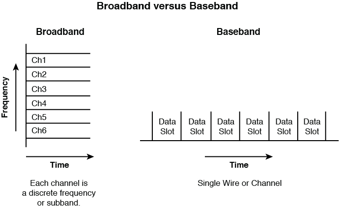
All data transfers use a communication channel. Multiple transmissions might need to use the same channel. Sharing this medium can be done in two different ways: broadband or baseband. The difference is in how the medium is shared.
In baseband, the entire medium is used for a single transmission, and then multiple transmission types are assigned time slots to use this single circuit. This is called time division multiplexing (TDM). Multiplexing is the process of using the same medium for multiple transmissions. The transmissions take turns rather than sending at the same time.
Broadband, on the other hand, divides the medium in different frequencies, a process called frequency division multiplexing (FDM). This has the benefit of allowing true simultaneous use of the medium.
An example of broadband transmission is Digital Subscriber Line (DSL), where the phone signals are sent at one frequency and the computer data at another. This is why you can talk on the phone and use the Web at the same time. Figure 4-11 illustrates these two processes.
Unicast, Multicast, and Broadcast
When systems are communicating in a network, they might send out three types of transmissions. These methods differ in the scope of their reception as follows:
Unicast: Transmission from a single system to another single system. It is considered one-to-one.
Multicast: A signal is received by all others in a group called a multicast group. It is considered one-to-many.
Broadcast: A transmission sent by a single system to all systems in the network. It is considered one-to-all.
Figure 4-12 illustrates the three methods.

Wired Versus Wireless
As you probably know by now, not all transmissions occur over a wired connection. Even within the category of wired connections, the way in which the ones and zeros are represented can be done in different ways. In a copper wire, the ones and zeros are represented with changes in the voltage of the signal, whereas in a fiber optic cable, they are represented with manipulation of a light source (lasers or light-emitting diodes [LEDs]).
In wireless transmission, radio waves or light waves are manipulated to represent the ones and zeros. When infrared technology is used, this is done with infrared light. With wireless LANs (WLANs), radio waves are manipulated to represent the ones and zeros. These differences in how the bits are represented occur at the Physical and Data Link layers of the OSI model. When a packet goes from a wireless section of the network to a wired section, these two layers are the only layers that change.
When a different physical medium is used, typically a different Layer 2 protocol is called for. For example, while the data is traveling over the wired Ethernet network, the 802.3 standard is used. However, when the data gets to a wireless section of the network, it needs a different Layer 2 protocol. Depending on the technology in use, it could be either 802.11 (WLAN) or 802.16 (WiMAX).
The ability of the packet to traverse various media types is just another indication of the independence of the OSI layers because the information in Layers 3–7 remains unchanged regardless of how many Layer 2 transitions must be made to get the data to its final destination.
IPv6
IPv6 was developed to more cleanly address the issue of the exhaustion of the IPv4 space. Although private addressing and the use of NAT have helped to delay the inevitable, the use of NAT introduces its own set of problems. The IPv6 system uses 128 bits so it creates such a large number of possible addresses that it is expected to suffice for many, many years.
IPv6 addresses look different than IPv4 addresses because they use a different format and use the hexadecimal number system, so there are letters and numbers in them such as you would see in a MAC address. There are eight fields separated by colons, not dots. Here is a sample IPv6 address:
2001:00000:4137:9e76:30ab:3035:b541:9693
Many of the security features that were add-ons to IPv4 (such as IPsec) have been built into IPv6, increasing its security. Moreover, while DHCP can be used with IPv6, IPv6 provides a host the ability to locate its local router, configure itself, and discover the IP addresses of its neighbors. Finally, broadcast traffic is completely eliminated in IPv6 and replaced by multicast communications.
Table 4-4 shows the differences between IPv4 and IPv6.
Table 4-4 Differences Between IPv4 and IPv6 (Adapted from NIST SP 800-119)
Property |
IPv4 |
IPv6 |
|---|---|---|
Address size and network size |
32 bits, network size 8–30 bits |
128 bits, network size 64 bits |
Packet header size |
20–60 bytes |
40 bytes |
Header-level extension |
Limited number of small IP options |
Unlimited number of IPv6 extension headers |
Fragmentation |
Sender or any intermediate router allowed to fragment |
Only sender may fragment |
Control protocols |
Mixture of non-IP (ARP), ICMP, and other protocols |
All control protocols based on ICMPv6 |
Minimum allowed MTU |
576 bytes |
1280 bytes |
Path MTU discovery |
Optional, not widely used |
Strongly recommended |
Address assignment |
Usually one address per host |
Usually multiple addresses per interface |
Address types |
Use of unicast, multicast, and broadcast address types |
Broadcast addressing no longer used; use of unicast, multicast, and anycast address types |
Address configuration |
Devices configured manually or with host configuration protocols like DHCP |
Devices configure themselves independently using stateless address autoconfiguration (SLAAC) or use DHCP |
NIST SP 800-119
NIST Special Publication (SP) 800-119 provides guidelines for the secure deployment of IPv6. According to this SP, organizations planning the deployment of IPv6 should consider the following during the planning process:
IPv6 is a new protocol that is not backward compatible with IPv4.
In most cases IPv4 will still be a component of an IT infrastructure. As such, even after the deployment of IPv6, organizations will require mechanisms for IPv6 and IPv4 co-existence.
IPv6 can be deployed just as securely as IPv4, although it should be expected that vulnerabilities within the protocol, as well as with implementation errors, will lead to an initial increase in IPv6-based vulnerabilities. As a successor to IPv4, IPv6 does incorporate many of the lessons learned by the IETF for IPv4.
IPv6 has already been deployed and is currently in operation in large networks globally.
To overcome possible obstacles associated with deploying IPv6, organizations should consider the following recommendations:
Encourage staff to increase their knowledge of IPv6 to a level comparable with their current understanding of IPv4.
Plan a phased IPv6 deployment utilizing appropriate transition mechanisms to support business needs; don’t deploy more transition mechanisms than necessary.
Plan for a long transition period with dual IPv4/IPv6 co-existence.
Organizations that are not yet deploying IPv6 globally should implement the following recommendations:
Block all IPv6 traffic, native and tunneled, at the organization’s firewall. Both incoming and outgoing traffic should be blocked.
Disable all IPv6-compatible ports, protocols, and services on all software and hardware.
Begin to acquire familiarity and expertise with IPv6, through laboratory experimentation and/or limited pilot deployments.
Make organization web servers, located outside of the organizational firewall, accessible via IPv6 connections. This will enable IPv6-only users to access the servers and aid the organization in acquiring familiarity with some aspects of IPv6 deployment.
Organizations that are deploying IPv6 should implement the following recommendations to mitigate IPv6 threats:
Apply an appropriate mix of different types of IPv6 addressing (privacy addressing, unique local addressing, sparse allocation, and so on) to limit access and knowledge of IPv6-addressed environments.
Use automated address management tools to avoid manual entry of IPv6 addresses, which is prone to error because of their length.
Develop a granular ICMPv6 (ICMP for IPv6) filtering policy for the enterprise. Ensure that ICMPv6 messages that are essential to IPv6 operation are allowed, but others are blocked.
Use IPsec to authenticate and provide confidentiality to assets that can be tied to a scalable trust model (an example is access to Human Resources assets by internal employees that make use of an organization’s public key infrastructure [PKI] to establish trust).
Identify capabilities and weaknesses of network protection devices in an IPv6 environment.
Enable controls that might not have been used in IPv4 due to a lower threat level during initial deployment (implementing default deny access control policies, implementing routing protocol security, and so on).
Pay close attention to the security aspects of transition mechanisms such as tunneling protocols.
Ensure that IPv6 routers, packet filters, firewalls, and tunnel endpoints enforce multicast scope boundaries and make sure that Multicast Listener Discovery (MLD) packets are not inappropriately routable.
Be aware that switching from an environment in which NAT provides IP addresses to unique global IPv6 addresses could trigger a change in the Federal Information Security Management Act (FISMA) system boundaries.
The following sections on IPv6 are adapted from NIST SP 800-119. For more information on IPv6 beyond what is provided here, please refer to NIST SP 800-119.
IPv6 Major Features
According to NIST SP 800-119, IPv6 has many new or improved features that make it significantly different from its predecessor. These features include extended address space, autoconfiguration, header structure, extension headers, IPsec, mobility, quality of service, route aggregation, and efficient transmission.
Extended Address Space
Each IPv4 address is typically 32 bits long and is written as four decimal numbers representing 8-bit octets and separated by decimal points or periods. An example address is 172.30.128.97. Each IPv6 address is 128 bits long (as defined in RFC 4291) and is written as eight 16-bit fields in colon-delimited hexadecimal notation (an example is fe80:43e3:9095:02e5:0216:cbff:feb2:7474). This new 128-bit address space provides an enormous number of unique addresses, 2128 (or 3.4 × 1038) addresses, compared with IPv4’s 232 (or 4.3 × 10⁹) addresses.
Autoconfiguration
Essentially plug-and-play networking, IPv6 Stateless Address Auto-configuration is one of the most interesting and potentially valuable addressing features in IPv6. This feature allows devices on an IPv6 network to configure themselves independently using a stateless protocol. In IPv4, hosts are configured manually or with host configuration protocols like DHCP; with IPv6, autoconfiguration takes this a step further by defining a method for some devices to configure their IP addresses and other parameters without the need for a server. Moreover, it also defines a method, renumbering, whereby the time and effort required to renumber a network by replacing an old prefix with a new prefix are vastly reduced.
Header Structure
The IPv6 header is much simpler than the IPv4 header and has a fixed length of 40 bytes (as defined in RFC 2460). Even though this header is almost twice as long as the minimum IPv4 header, much of the header is taken up by two 16-byte IPv6 addresses, leaving only 8 bytes for other header information. This allows for improved fast processing of packets and protocol flexibility.
Extension Headers
An IPv4 header can be extended from 20 bytes to a maximum of 60 bytes, but this option is rarely used because it impedes performance and is often administratively prohibited for security reasons. IPv6 has a new method to handle options, which allows substantially improved processing and avoids some of the security problems that IPv4 options generated. IPv6 RFC 2460 defines six extension headers: hop-by-hop option header, routing header, fragment header, destination options header, authentication header (AH), and encapsulating security payload (ESP) header. Each extension header is identified by the Next Header field in the preceding header.
Mandatory IPsec Support
IP Security (IPsec) is a suite of protocols for securing IP communications by authenticating the sender and providing integrity protection plus, optionally, confidentiality for the transmitted data. This is accomplished through the use of two extension headers: ESP and AH. The negotiation and management of IPsec security protections and the associated secret keys are handled by the Internet Key Exchange (IKE) protocol. IPsec is a mandatory part of an IPv6 implementation; however, its use is not required. IPsec is also specified for securing particular IPv6 protocols (e.g., Mobile IPv6 and OSPFv3 [Open Shortest Path First version 3]).
Mobility
Mobile IPv6 (MIPv6) is an enhanced protocol supporting roaming for a mobile node, so that it can move from one network to another without losing IP-layer connectivity (as defined in RFC 3775). Mobile IPv6 uses IPv6’s vast address space and Neighbor Discovery (RFC 4861) to solve the handover problem at the network layer and maintain connections to applications and services if a device changes its temporary IP address. Mobile IPv6 also introduces new security concerns such as route optimization (RFC 4449) where data flow between the home agent and mobile node will need to be appropriately secured.
Quality of Service
IP (for the most part) treats all packets alike, as they are forwarded with best-effort treatment and no guarantee for delivery through the network. TCP adds delivery confirmations but has no options to control parameters such as delay or bandwidth allocation. Quality of Service (QoS) offers enhanced policy-based networking options to prioritize the delivery of information. Existing IPv4 and IPv6 implementations use similar QoS capabilities, such as Differentiated Services and Integrated Services, to identify and prioritize IP-based communications during periods of network congestion. Within the IPv6 header two fields can be used for QoS, the Traffic Class and Flow Label fields. The new Flow Label field and enlarged Traffic Class field in the main IPv6 header allow more efficient and finer grained differentiation of various types of traffic. The new Flow Label field can contain a label identifying or prioritizing a certain packet flow such as Voice over IP (VoIP) or videoconferencing, both of which are sensitive to timely delivery. IPv6 QoS is still a work in progress and security should be given increased consideration in this stage of development.
Route Aggregation
IPv6 incorporates a hierarchal addressing structure and has a simplified header allowing for improved routing of information from a source to a destination. The large amount of address space allows organizations with large numbers of connections to obtain blocks of contiguous address space.
Contiguous address space allows organizations to aggregate addresses under one prefix for identification on the Internet. This structured approach to addressing reduces the amount of information Internet routers must maintain and store and promotes faster routing of data. Additionally, it is envisioned that IPv6 addresses will primarily be allocated only from ISPs to customers. This will allow for ISPs to summarize route advertisements to minimize the size of the IPv6 Internet routing tables.
Efficient Transmission
IPv6 packet fragmentation control occurs at the IPv6 source host, not at an intermediate IPv6 router. With IPv4, a router can fragment a packet when the maximum transmission unit (MTU) of the next link is smaller than the packet it has to send. The router does this by slicing a packet to fit into the smaller MTU and sends it out as a set of fragments. The destination host collects the fragments and reassembles them. All fragments must arrive for the higher-level protocol to get the packet. Therefore, when one fragment is missing or an error occurs, the entire transmission has to be redone.
In IPv6, a host uses a procedure called Path Maximum Transmission Unit Discovery (PMTUD) to learn the path MTU size and eliminate the need for routers to perform fragmentation. The IPv6 Fragment Extension Header is used when an IPv6 host wants to fragment a packet, so fragmentation occurs at the source host, not the router, which allows efficient transmission.
IPv4 Versus IPv6 Threat Comparison
Based on the threat comparison between IPv4 and IPv6, the following actions are recommended to mitigate IPv6 threats during the deployment process:
Apply different types of IPv6 addressing (privacy addressing, unique local addressing, sparse allocation, etc.) to limit access and knowledge of IPv6-addressed environments.
Assign subnet and interface identifiers randomly to increase the difficulty of network scanning.
Develop a granular ICMPv6 filtering policy for the enterprise. Ensure that ICMPv6 messages that are essential to IPv6 operation are allowed, but others are blocked.
Use IPsec to authenticate and provide confidentiality to assets that can be tied to a scalable trust model (an example is access to Human Resources assets by internal employees that make use of an organization’s PKI to establish trust).
Identify capabilities and weaknesses of network protection devices in an IPv6 environment.
Enable controls that might not have been used in IPv4 due to a lower threat level during initial deployment (implementing default deny access control policies, implementing routing protocol security, etc.).
Pay close attention to the security aspects of transition mechanisms such as tunneling protocols.
On networks that are IPv4-only, block all IPv6 traffic.
IPv6 Addressing
According to NIST SP 800-119, IPv6 addresses are 128 bits long and are written in what is called colon-delimited hexadecimal notation. An IPv6 address is composed of eight distinct numbers representing 16 bits each and written in base-16 (hexadecimal or hex) notation. The valid hex digits are 0 through 9 and A through F and together with the colon separator are the only characters that can be used for writing an IPv6 address. A comparison of IPv4 and IPv6 addressing conventions is illustrated in Figure 4-13.

An example of an IPv6 address is
2001:0db8:9095:02e5:0216:cbff:feb2:7474
Note that the address contains eight distinct four-place hex values, separated by colons. Each of these values represents 16 bits, for a total of 128 bits in the entire address.
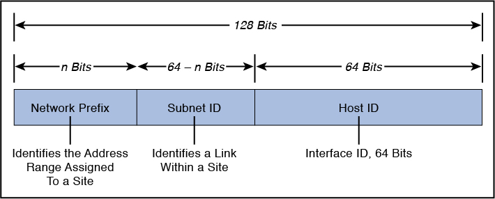
IPv6 addresses are divided among the network prefix, the subnet identifier, and the host identifier portions of the address. The network prefix is the high-order bits of an IP address, used to identify a specific network and, in some cases, a specific type of address. The subnet identifier (subnet ID) identifies a link within a site. The subnet ID is assigned by the local administrator of the site; a single site can have multiple subnet IDs. This is used as a designator for the network upon which the host bearing the address is resident. The host identifier (host ID) of the address is a unique identifier for the node within the network upon which it resides. It is identified with a specific interface of the host. Figure 4-14 depicts the IPv6 address format with the network prefix, subnet identifier, and host identifier.
There is no subnet mask in IPv6, although the slash notation used to identify the network address bits is similar to IPv4’s subnet mask notation. The IPv6 notation appends the prefix length and is written as a number of bits with a slash, which leads to the following format: IPv6 address/prefix length. The prefix length specifies how many of the address’s left-most bits comprise the network prefix. An example address with a 32-bit network prefix is 2001:0db8:9095:02e5:0216:cbff:feb2:7474/32.
Quantities of IPv6 addresses are assigned by the international registry services and ISPs based in part upon the size of the entity receiving the addresses. Large, top-tier networks may receive address allocations with a network prefix of 32 bits as long as the need is justified. In this case, the first two groupings of hex values, separated by colons, comprise the network prefix for the assignee of the addresses. The remaining 96 bits are available to the local administrator primarily for reallocation of the subnet ID and the host ID. The subnet ID identifies a link within a site, which can have multiple subnet IDs. The host ID within a network must be unique and identifies an interface on a subnet for the organization, similar to an assigned IPv4 address. Figure 4-15 depicts an IPv6 address with 32 bits allocated to the network prefix.

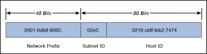
Government, educational, commercial, and other networks typically receive address allocations from top-tier ISPs with a network prefix of 48 bits (/48), leaving 80 bits for the subnet identifier and host identifier. Figure 4-16 depicts an IPv6 address with 48 bits allocated to the network prefix.
Subnets within an organization often have network prefixes of 64 bits (/64), leaving 64 bits for allocation to hosts’ interfaces. The host ID should use a 64-bit interface identifier that follows EUI-64 (Extended Unique Identifier) format when a global network prefix is used (001 to 111), except in the case when multicast addresses (1111 1111) are used. Figure 4-17 depicts an IPv6 address with 64 bits allocated to the network prefix.

Shorthand for Writing IPv6 Addresses
According to NIST SP 800-119, IPv6 addresses do not lend themselves to human memorization due to their length. Administrators of IPv4 networks typically can recall multiple IPv4 network and host addresses; remembering multiple IPv6 network and host addresses is more challenging. The notation for IPv6 addresses may be compressed and simplified under specific circumstances.
One to three zeros that appear as the leading digits in any colon-delimited hexadecimal grouping may be dropped. This simplifies the address and makes it easier to read and to write. For example:
2001:0db8:0aba:02e5:0000:0ee9:0000:0444/48
becomes
2001:db8:aba:2e5:0:ee9:0:444/48
It is important to note that trailing zeros may not be dropped, because they have intrinsic place value in the address format.
Further efficiency is gained by combining all-zero portions of the address. Any colon-delimited portion of an address containing all zeros may be compressed so that nothing appears between the leading and trailing colons. For example:
2001:0db8:0055:0000:cd23:0000:0000:0205/48
becomes
2001:db8:55:0:cd23::205/48
In this example, the sixth and seventh 16-bit groupings contain all zeros; they were compressed by eliminating the zeros completely, as well as the colon that divided the two groupings. Nevertheless, compressing an address by removing one or more consecutive colons between groups of zeros may only be done once per address. The fourth 16-bit grouping in the example also contains all zeros, but in the condensed form of the address, it is represented with a single zero. A choice had to be made as to which group of zeros was to be compressed. The example address could be written
2001:db8:55::cd23:0:0:205/48
but this is not as efficient as
2001:db8:55:0:cd23::205/48
It is important to note that both of the addresses in the preceding paragraph are properly formatted, but the latter address is shorter. Compression is just a convention for writing addresses, it does not affect how an address is used, and it makes no difference whether compression falls within the network prefix, host identifier, or across both portions of the address.
IPv6 Address Types
According to NIST SP 800-119, IPv6 addressing differs from IPv4 in several ways aside from the address size. In both IPv4 and IPv6, addresses specifically belong to interfaces, not to nodes. However, because IPv6 addresses are not in short supply, interfaces often have multiple addresses. IPv6 addresses consist of a network prefix in the higher order bits and an interface identifier in the lower order bits. Moreover, the prefix indicates a subnet or link within a site, and a link can be assigned multiple subnet IDs.
Many IPv6 address ranges are reserved or defined for special purposes by the IETF’s IPv6 standards and by IANA. Table 4-5 lists the major assignments and how to identify the different types of IPv6 address from the high-order bits.
Table 4-5 IPv6 Address Types (Copied from NIST SP 800-119)
Address Type |
IPv6 Notation |
Uses |
|---|---|---|
Embedded IPv4 address |
::FFFF/96 |
Prefix for embedding IPv4 address in an IPv6 address |
Loopback |
::1/128 |
Loopback address on every interface |
Global unicast |
2000::/3 |
Global unicast and anycast (allocated) |
Global unicast |
4000::/2–FC00::/9 |
Global unicast and anycast (unallocated) |
Teredo |
2001:0000::/32 |
Teredo |
Nonroutable |
2001:DB8::/32 |
Nonroutable. Documentation purposes only |
6to4 |
2002::/16 |
6to4 |
6Bone |
3FFE::/16 |
Deprecated. 6Bone testing assignment, 1996 through mid-2006 |
Link-local unicast |
FE80::/10 |
Link-local unicast |
Reserved |
FEC0::/10 |
Deprecated. Formerly Site-local address space, unicast and anycast |
Local IPv6 address |
FC00::/7 |
Unicast Unique local address space, unicast and anycast |
Multicast |
FF00::/8 |
Multicast address space |
IPv6 uses the notion of address types for different situations. These different address types are defined below:
Unicast addresses: Addresses that identify one interface on a single node; a packet with a unicast destination address is delivered to that interface.
Multicast addresses: RFC 4291 defines a multicast address as “An identifier for a set of interfaces (typically belonging to different nodes). A packet sent to a multicast address is delivered to all interfaces identified by that address.” Although multicast addresses are common in both IPv4 and IPv6, in IPv6 multicasting has new applications. The single most important aspect of multicast addressing under IPv6 is that it enables fundamental IPv6 functionality, including neighbor discovery (ND) and router discovery. Multicast addresses begin with FF00::/8. They are intended for efficient one-to-many and many-to-many communication. The IPv6 standards prohibit sending packets from a multicast address; multicast addresses are valid only as destinations.
Anycast addresses: Addresses that can identify several interfaces on one or more nodes; a packet with an anycast destination address is delivered to one of the interfaces bearing the address, usually the closest one as determined by routing protocols. Anycast addressing was introduced as an add-on for IPv4, but it was designed as a basic component of IPv6.
The format of anycast addresses is indistinguishable from unicast addresses.
Broadcast addressing is a common attribute of IPv4, but is not defined or implemented in IPv6. Multicast addressing in IPv6 meets the requirements that broadcast addressing formerly fulfilled.
IPv6 Address Scope
According to NIST SP 800-119, in the original design for IPv6, link-local, site-local, and global addresses were defined; later, it was realized that site-local addresses were not well enough defined to be useful. Site-local addresses were abandoned and replaced with unique local addresses. Older implementations of IPv6 may still use site-local addresses, so IPv6 firewalls need to recognize and handle site-local addresses correctly.
The IPv6 standards define several scopes for meaningful IPv6 addresses:
Interface-local: This applies only to a single interface; the loopback address has this scope.
Link-local: This applies to a particular LAN or network link; every IPv6 interface on a LAN must have an address with this scope. Link-local addresses start with FE80::/10. Packets with link-local destination addresses are not routable and must not be forwarded off the local link.
Link-local addresses are used for administrative purposes such as neighbor and router discovery.
Site-local: This scope was intended to apply to all IPv6 networks or a single logical entity such as the network within an organization. Addresses with this scope start with FEC0::/10. They were intended not to be globally routable but potentially routed between subnets within an organization. Site-local addresses have been deprecated and replaced with unique local addresses.
Unique local unicast: This scope is meant for a site, campus, or enterprise’s internal addressing. It replaces the deprecated site-local concept. Unique local addresses (ULAs) may be routable within an enterprise. Use of unique local addresses is not yet widespread.
Global: The global scope applies to the entire Internet. These are globally unique addresses that are routable across all publicly connected networks.
Embedded IPv4 unicast: The IPv6 specification has the ability to leverage existing IPv4 addressing schemes. The transition to IPv6 will be gradual, so two special types of addresses have been defined for backward compatibility with IPv4: IPv4-compatible IPv6 addresses (rarely used and deprecated in RFC 4291) and IPv4-mapped IPv6 addresses. Both allow the protocol to derive addresses by embedding IPv4 addresses in the body of an IPv6 address. An IPv4-mapped IPv6 address is used to represent the addresses of IPv4-only nodes as an IPv6 address, which allows an IPv6 node to use this address to send a packet to an IPv4-only node.
IPv6 makes use of addresses other than those shown above. The unspecified address consists of all zeros (0:0:0:0:0:0:0:0 or simply ::) and may be the source address of a node soliciting its own IP address from an address assignment authority (such as a DHCPv6 server). IPv6-compliant routers never forward a packet with an unspecified address. The loopback address is used by a node to send a packet to itself. The loopback address, 0:0:0:0:0:0:0:1 (or simply ::1), is defined as being interface local.
IPv6-compliant hosts and routers never forward packets with a loopback destination.
Network Types
So far we have discussed network topologies and technologies, so now let’s look at a third way to describe networks: network type. Network type refers to the scope of the network. Is it a LAN or a WAN? Is it a part of the internal network, or is it an extranet? This section discusses and differentiates all these network types.
LAN
First let’s talk about what makes a local area network (LAN) local. Although classically we think of a LAN as a network located in one location, such as a single office, referring to a LAN as a group of systems that are connected with a fast connection is more correct. For purposes of this discussion, that is any connection over 10 Mbps.
That might not seem very fast to you, but it is when compared to a WAN. Even a T1 connection is only 1.544 Mbps. Using this as our yardstick, if a single campus network has a WAN connection between two buildings, then the two networks are considered two LANs rather than a single LAN. In most cases, however, networks in a single campus are typically not connected with a WAN connection, which is why usually you hear a LAN defined as a network in a single location.
Intranet
Within the boundaries of a single LAN, there can be subdivisions for security purposes. The LAN might be divided into an intranet and an extranet. The intranet is the internal network of the enterprise. It would be considered a trusted network and typically houses any sensitive information and systems and should receive maximum protection with firewalls and strong authentication mechanisms.
Extranet
An extranet is a network logically separate from the intranet where resources that will be accessed from the outside world are made available. Access might be granted to customers, business partners, and the public in general. All traffic between this network and the intranet should be closely monitored and securely controlled. Nothing of a sensitive nature should be placed in the extranet.
MAN
A metropolitan area network (MAN) is a type of LAN that encompasses a large area such as the downtown of a city. In many cases it is a backbone that is provided for LANs to hook into. Three technologies are usually used in a MAN:
Fiber Distributed Data Interface (FDDI)
Synchronous Optical Networking (SONET)
Metro Ethernet
FDDI and SONET rings, which both rely on fiber cabling, can span large areas, and businesses can connect to the rings using T1, fractional T1, or T3 connections. FDDI rings are a double ring with fault tolerance built in. SONET is also self- healing, meaning it has a double ring with a backup line if a line goes bad.
Metro Ethernet is the use of Ethernet technology over a wide area. It can be pure Ethernet or a combination of Ethernet and other technologies such as the ones mentioned in this section. Traditional Ethernet (the type used on a LAN) is less scalable. It is often combined with Multiprotocol Label Switching (MPLS) technology, which is capable of carrying packets of various types, including Ethernet.
Less capable MANs often feed into MANs of higher capacity. Conceptually, you can divide the MAN architecture into three sections: customer, aggregation, and core layer. The customer section is the local loop that connects from the customer to the aggregation network, which then feeds into the high-speed core. The high-speed core connects the aggregation networks to one another.
WAN
WANs are used to connect LANs and MANs together. Many technologies can be used for these connections. They vary in capacity and cost, and access to these networks is purchased from a telecommunications company. The ultimate WAN is the Internet, the global backbone to which all MANs and LANs are connected. However, not all WANs connect to the Internet because some are private, dedicated links to which only the company paying for them has access.
WLAN
A wireless local area network (WLAN) allows devices to connect wirelessly to each other via a wireless access point (WAP). Multiple WAPs can work together to extend the range of the WLAN. WLAN technologies are discussed in more detail later in this chapter.
SAN
A storage area network (SAN) provides a connection to data storage devices through a technology like Fibre Channel or iSCSI, both of which are discussed in more detail later in this chapter.
CAN
A campus area network (CAN) includes multiple LANs but is smaller than a MAN. A CAN could be implemented on a hospital or local business campus.
PAN
A personal area network (PAN) includes devices, such as computers, telephones, tablets, and mobile phones, that are in close proximity with one another. PANs are usually implemented using Bluetooth, Z-Wave, Zigbee, and Infrared Data Association (IrDA).
Protocols and Services
Many protocols and services have been developed over the years to add functionality to networks. In many cases these protocols reside at the Application layer of the OSI model. These Application layer protocols usually perform a specific function and rely on the lower layer protocols in the TCP/IP suite and protocols at Layer 2 (like Ethernet) to perform routing and delivery services.
This section covers some of the most important of these protocols and services, including some that do not operate at the Application layer, focusing on the function and port number of each. Port numbers are important to be aware of from a security standpoint because in many cases port numbers are referenced when configuring firewall rules. In cases where a port or protocol number is relevant, it will be given as well.
ARP/RARP
Address Resolution Protocol (ARP), one of the protocols in the TCP/IP suite, operates at Layer 3 of the OSI model. The information it derives is utilized at Layer 2, however. ARP’s job is to resolve the destination IP address placed in the header by IP to a Layer 2 or MAC address. Remember, when frames are transmitted on a local segment the transfer is done in terms of MAC addresses, not IP addresses, so this information must be known.
Whenever a packet is sent across the network, at every router hop and again at the destination subnet, the source and destination MAC address pairs change but the source and destination IP addresses do not. The process that ARP uses to perform this resolution is called an ARP broadcast.
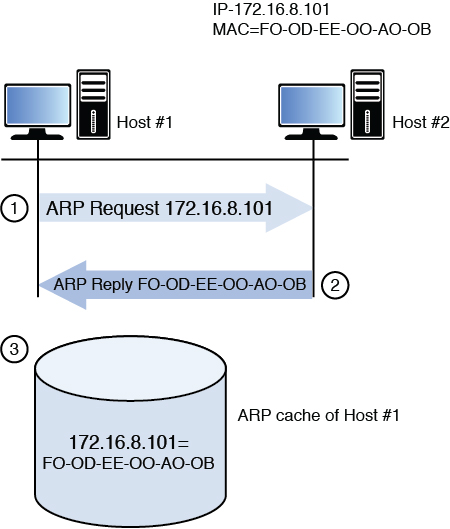
First an area of memory called the ARP cache is consulted. If the MAC address has been recently resolved, the mapping will be in the cache and a broadcast is not required. If the record has aged out of the cache, ARP sends a broadcast frame to the local network that all devices will receive. The device that possesses the IP address responds with its MAC address. Then ARP places the MAC address in the frame and sends the frame. Figure 4-18 illustrates this process.
Reverse ARP (RARP) resolves MAC addresses to IP addresses.
In IPv6 networks, the functionality of ARP is provided by the Neighbor Discovery Protocol (NDP).
DHCP/BOOTP
Dynamic Host Configuration Protocol (DHCP) is a service that can be used to automate the process of assigning an IP configuration to the devices in the network. A DHCP server uses the bootstrap protocol (BOOTP) to perform its functions. Manual configuration of an IP address, subnet mask, default gateway, and DNS server is not only time-consuming but fraught with opportunity for human error. Using DHCP can not only automate this, but can also eliminate network problems from this human error.
DHCP is a client/server program. All modern operating systems contain a DHCP client, and the server component can be implemented either on a server or on a router. When a computer that is configured to be a DHCP client starts, it performs a precise four-step process to obtain its configuration. Conceptually, the client broadcasts for the IP address of the DHCP server. All devices receive this broadcast, but only DHCP servers respond. The device accepts the configuration offered by the first DHCP server from which it hears. The process uses four packets with distinctive names (see Figure 4-19). DHCP uses UDP ports 67 and 68. Port 67 sends data to the server, and port 68 sends data to the client.
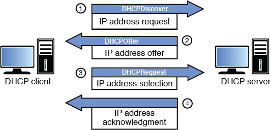
DNS
Just as DHCP relieves us from having to manually configure the IP configuration of each system, Domain Name System (DNS) relieves all humans from having to know the IP address of every computer with which they want to communicate. Ultimately, an IP address must be known to connect to another computer. DNS resolves a computer name (or in the case of the Web, a domain name) to an IP address.
DNS is another client/server program with the client included in all modern operating systems. The server part resides on a series of DNS servers located both in the local network and on the Internet. When a DNS client needs to know the IP address that goes with a particular computer name or domain name, it queries the local DNS server. If the local DNS server does not have the resolution, it contacts other DNS servers on the client’s behalf, learns the IP address, and relays that information to the DNS client. DNS uses UDP port 53 and TCP port 53. The DNS servers use TCP port 53 to exchange information, and the DNS clients use UDP port 53 for queries.
FTP, FTPS, SFTP, TFTP
File Transfer Protocol (FTP), and its more secure versions FTPS and SFTP, transfers files from one system to another. FTP is insecure in that the username and password are transmitted in cleartext. The original cleartext version uses TCP port 20 for data and TCP port 21 as the control channel. Using FTP when security is a consideration is not recommended.
FTPS is FTP that adds support for the Transport Layer Security (TLS) and the Secure Sockets Layer (SSL) cryptographic protocols. FTPS uses TCP ports 989 and 990.
FTPS is not the same as and should not be confused with another secure version of FTP, SSH File Transfer Protocol (SFTP). This is an extension of the Secure Shell (SSH) protocol. There have been a number of different versions, with version 6 being the latest. Because it uses SSH for the file transfer, it uses TCP port 22.
Trivial FTP (TFTP) does not use authentication and runs over UDP port 69.
HTTP, HTTPS, S-HTTP
One of the most frequently used protocols today is Hypertext Transfer Protocol (HTTP) and its secure versions, HTTPS and S-HTTP. This protocol is used to view and transfer web pages or web content between a web server and a web client. With each new address that is entered into the web browser, whether from initial user entry or by clicking a link on the page displayed, a new connection is established because HTTP is a stateless protocol. The original version (HTTP) has no encryption, so when security is a concern, one of the two secure versions should be used. HTTP uses TCP port 80.
Hypertext Transfer Protocol Secure (HTTPS) layers HTTP on top of the SSL/TLS protocol, thus adding the security capabilities of SSL/TLS to standard HTTP communications. SSL/TLS keeps the session open using a secure channel. HTTPS websites will always include the https:// designation at the beginning. It is often used for secure websites because it requires no software or configuration changes on the web client to function securely. When HTTPS is used, port 80 is not used. Rather, it uses port 443.
Unlike HTTPS, which encrypts the entire communication, S-HTTP encrypts only the served page data and submitted data such as POST fields, leaving the initiation of the protocol unchanged. Secure-HTTP and HTTP processing can operate on the same TCP port, port 80. This version is rarely used.
ICMP
Internet Control Message Protocol (ICMP) operates at Layer 3 (Network layer) of the OSI model and is used by devices to transmit error messages regarding problems with transmissions. It also is the protocol used when the ping and traceroute commands are used to troubleshoot network connectivity problems.
ICMP announces network errors and network congestion. It also assists in troubleshooting and announces timeouts.
ICMP is a protocol that can be leveraged to mount several network attacks based on its operation, and for this reason many networks choose to block ICMP.
IGMP
Internet Group Management Protocol (IGMP) provides multicasting capabilities to devices. Multicasting allows devices to transmit data to multiple recipients. IGMP is used by many gaming platforms.
IMAP
Internet Message Access Protocol (IMAP) is an Application layer protocol for email retrieval. Its latest version is IMAP4. It is a client email protocol used to access email from a server. Unlike POP3, another email client that can only download messages from the server, IMAP4 allows one to download a copy and leave a copy on the server. IMAP4 uses port 143. A secure version also exists, IMAPS (IMAP over SSL), that uses port 993.
LDAP
Lightweight Directory Access Protocol (LDAP) is a directory query protocol that is based on the X.500 series of computer networking standards. Vendor implementations of LDAP include Microsoft’s Active Directory Services, NetIQ’s eDirectory, and Network Information Service (NIS). By default, LDAP uses TCP/UDP port 389.
LDP
Label Distribution Protocol (LDP) allows routers capable of MPLS to exchange label mapping information. Two routers with an established session are called LDP peers and the exchange of information is bidirectional. For inner label distribution, targeted LDP (tLDP) is used. LDP and tLDP discovery runs on UDP port 646, and the session is built on TCP port 646.
NAT
Network address translation (NAT) is a service that maps private IP addresses to public IP addresses. It is discussed in the section “Logical and Physical Addressing,” earlier in this chapter.
NetBIOS
Network Basic Input/Output System (NetBIOS) is an API. NetBIOS over TCP/IP (NetBT) runs on TCP ports 137, 138, and 139.
NFS
Network File System (NFS) is a client/server file-sharing protocol used in UNIX/Linux. Version 4 is the most current version of NFS. It operates over TCP port 2049. Secure NFS (SNFS) offers confidentiality using Digital Encryption Standard (DES).
PAT
Port address translation (PAT) is a specific version of NAT that uses a single public IP address to represent multiple private IP addresses. Its operation is discussed in the section “Logical and Physical Addressing,” earlier in this chapter.
POP
Post Office Protocol (POP) is an Application layer email retrieval protocol. POP3 is the latest version. It allows for downloading messages only and does not allow the additional functionality provided by IMAP4. POP3 uses port 110. A version that runs over SSL is also available that uses port 995.
CIFS/SMB
Common Internet File System (CIFS)/Server Message Block (SMB) is a file-sharing protocol. It uses TCP port 445.
SMTP
POP and IMAP are client email protocols used for retrieving email, but when email servers are talking to each other, they use a protocol called Simple Mail Transfer Protocol (SMTP), a standard Application layer protocol. This is also the protocol used by clients to send email. SMTP uses port 25, and when it is run over SSL, it uses port 465.
Enhanced SMTP (ESMTP) allows larger field sizes and extension of existing SMTP commands.
SNMP
Simple Network Management Protocol (SNMP) is an Application layer protocol that is used to retrieve information from network devices and to send configuration changes to those devices. SNMP uses TCP port 162 and UDP ports 161 and 162.
SNMP devices are organized into communities and the community name must be known to either access information from or send a change to a device. It also can be used with a password. SNMP versions 1 and 2 are susceptible to packet sniffing, and all versions are susceptible to brute-force attacks on the community strings and password used. The defaults of community string names, which are widely known, are often left in place. The latest version, SNMPv3, is the most secure.
SSL/TLS
Secure Sockets Layer (SSL) is a Transport layer protocol that provides encryption, server and client authentication, and message integrity. SSL was developed by Netscape to transmit private documents over the Internet. While SSL implements either 40-bit (SSL 2.0) or 128-bit encryption (SSL 3.0), the 40-bit version is susceptible to attacks because of its limited key size. SSL allows an application to have encrypted, authenticated communication across a network. SSL has been deprecated and replaced by TLS.
Transport Layer Security (TLS) is an open-community standard that provides many of the same services as SSL. TLS 1.0 is based upon SSL 3.0 but is more extensible. The main goal of TLS is privacy and data integrity between two communicating applications.
TLS 1.1 was an update to TLS 1.0 that provides protection against cipher-block chaining (CBC) attacks. TLS 1.2 used MDS-SHA-1 with pseudorandom functions (PRFs).
TLS 1.2 is latest version of TLS. TLS 1.2 provides access to advanced cipher suites that support elliptic curve cryptography (ECC) and block cipher modes. TLS 1.3 removes support for weaker elliptic curves. TLS 1.3 is also faster and provides better encryption.
SSL and TLS are most commonly used when data needs to be encrypted while it is being transmitted (in transit) over a medium from one system to another. When other protocols include SSL/TLS in their implementation to improve security, the protocols usually operate over a different port than the standard, non-secured version.
Multilayer Protocols
Many protocols, such as FTP and DNS, operate on a single layer of the OSI model. However, many protocols operate at multiple layers of the OSI model. The best example is TCP/IP, the networking protocol used on the Internet and on the vast majority of LANs.
Many of the multilayer protocols were designed as part of proprietary protocols and have evolved into what they are today. Today multilayer protocols are being used to control critical infrastructure components, such as power grids and industrial control systems (ICSs). Because these critical infrastructure components were not originally designed for deployment over the Internet, unique challenges have arisen. It is virtually impossible to deploy antivirus software on an ICS. Many ICSs are installed without any thought to the physical security of the control system itself. Unlike in IT systems, delays in ICSs are unacceptable because of the time criticality of responding to emergencies. ICSs often have a lifetime much longer than the average IT system. Availability of ICSs is usually 24/7/365, whereas an IT system can tolerate short periods of unavailability. When you consider this and other issues, you can easily see why an organization should fully consider the security implications when deploying an ICS that uses multilayer protocols. Deploying a vendor-developed protocol is not always the answer because the protocols developed by the vendor are only concerned with uptime and device control, without any consideration of security.
Distributed Network Protocol version 3 (DNP3) is a multilayer protocol that is used between components in process automation systems in electric and water companies. It was developed for communications between various types of data acquisition and control equipment. It plays a crucial role in supervisory control and data acquisition (SCADA) systems.
Converged Protocols
IP convergence involves carrying different types of traffic over one network. The traffic includes voice, video, data, and images. It is based on the Internet Protocol.
When IP convergence is deployed, a single platform is used for all types of traffic, involving all devices. It supports multimedia applications. Management and flexibility of the network are greatly improved because there is uniform setup and the ability to mold communication patterns. QoS can be deployed to allow administrators to ensure that certain services have a higher priority than others.
Implementation of IP convergence includes FCoE, MPLS, VoIP, and Internet Small Computer System Interface (iSCSI).
FCoE
Fibre Channel over Ethernet (FCoE) is a protocol that encapsulates Fibre Channel frames over Ethernet networks, thereby allowing Fibre Channel to use 10-Gigabit Ethernet networks or higher while preserving the Fibre Channel protocol. FCoE uses the following ports to communicate among the FCoE devices:
Network (N) port: Connects a node to a Fibre Channel switch from the node. Also referred to as a node port.
Fabric (F) port: Connects the Fibre Channel fabric to a node from the switch.
Loop (L) port: Connects a node to a Fibre Channel loop from the node.
Network + loop (NL) port: Connects to both loops and switches from the node.
Fabric + loop (FL) port: Connects to both loops and switches from the switch.
Extender (E) port: Cascades Fibre Channel switches together, thereby extending the fabric.
General (G) port: Emulates other port types.
External (EX) port: Connects a Fibre Channel router and a Fibre Channel switch. The EX port is on the router side, and the E port is on the switch side.
Trunking E (TE) port: Allows multiple virtual SAN (VSAN) routing and provides standard E port functions.
FCoE has a number of benefits, including the following: Technicians need to wire the server only once, fewer cables and adapters are needed, the I/O uses software provisioning, interoperation with existing Fibre Channel SANs is possible, and gateways are not used.
MPLS
Multiprotocol Label Switching (MPLS) routes data from one node to the next based on short path labels rather than long network addresses, avoiding complex lookups in a routing table. It includes the ability to control how and where traffic is routed, delivers data transport services across the same network, and improves network resiliency through MPLS Fast Reroute.
MPLS uses Label Switched Path (LSP), which is a unidirectional tunnel between routers. An MPLS network may use the following roles:
Label edge router (LER): The first router that encapsulates a packet inside LSP and makes the path selection. This is commonly referred to as the ingress node.
Label switching router (LSR): A router that performs MPLS switching somewhere along the LSP. This is also referred to as the transit node.
Egress node: The last router at the end of an LSP.
When terminating an LSP, an implicit or explicit null can be used. Implicit nulls remove the label when it reaches the next-to-last hop. Explicit nulls keep the label to the last router.
When MPLS is deployed as part of a VPN, the following router roles can be used:
Provider (P) router: A backbone router that only performs label switching.
Provider edge (PE) router: A router that faces the customer that performs label popping and imposition. It can terminate multiple services.
Customer edge (CE) router: The customer router with which the PE router communicates.
MPLS uses two command routing protocols: Label Distribution Protocol (LDP) and Resource Reservation Protocol with Traffic Engineering (RSVP-TE). RSVP-TE is much more complex than LDP. LDP is used more on MPLS VPN, while RSVP-TE is required for traffic engineering.
VoIP
Voice over Internet Protocol (VoIP) includes technologies that deliver voice communications and multimedia sessions over IP networks, such as the Internet. VoIP is also referred to as IP telephony, Internet telephony, broadband telephony, and broadband phone service. VoIP can be implemented using a variety of protocols, including H.323, Session Initiation Protocol (SIP), Media Gateway Control Protocol (MGCP), and Real-time Transport Protocol (RTP). NIST SP 800-58 contains detailed information on the implementation of VoIP.
Note
VoIP is discussed in more detail later in this chapter.
iSCSI
Internet Small Computer System Interface (iSCSI) allows SCSI commands to be sent end-to-end over LANs, WANs, or the Internet over TCP. It provides storage consolidation and disaster recovery. iSCSI has a number of benefits, including the following: Technicians need to wire the server only once, fewer cables and adapters are needed, a new operational model is used, and there is broad industry support, including vendor iSCSI drivers, gateways, and native iSCSI storage arrays.
Wireless Networks
Perhaps the area of the network that keeps more administrators awake at night is the wireless portion of the network. In the early days of 802.11 WLAN deployments, many administrators chose to simply not implement wireless for fear of the security holes it creates. However, it became apparent that not only did users demand this, but in some cases users were bringing their own APs to work and hooking them up and suddenly there was a wireless network!
Today WLAN security has evolved to the point that security is no longer a valid reason to avoid wireless. This section offers a look at the protocols used in wireless, the methods used to convert the data into radio waves, the various topologies in which WLANs can be deployed, and security measures that should be taken.
FHSS, DSSS, OFDM, VOFDM, FDMA, TDMA, CDMA, OFDMA, and GSM
When data leaves an Ethernet NIC and is sent out on the network, the ones and zeros that constitute the data are represented with different electric voltages. In wireless, this information must be represented in radio waves. A number of different methods exist for performing this operation, which is called modulation. You should also understand some additional terms to talk intelligently about wireless. This section defines a number of terms to provide a background for the discussion found in the balance of this section. It covers techniques used in WLANs and techniques used in cellular networking.
802.11 Techniques
The following techniques are used in WLANs:
Frequency hopping spread spectrum (FHSS): FHSS and DSSS were a part of the original 802.11 standard. FHSS is unique in that it changes frequencies or channels every few seconds in a set pattern that both transmitter and receiver know. This is not a security measure because the patterns are well known, although it does make capturing the traffic difficult. It helps avoid interference by only occasionally using a frequency where the interference is present. Later amendments to the 802.11 standard did not include this technology. It can attain up to 2 Mbps.
Direct sequence spread spectrum (DSSS): DSSS and FHSS were a part of the original 802.11 standard. DSSS is the modulation technique used in 802.11b. The modulation technique used in wireless had a huge impact on throughput. In the case of DSSS, it spreads the transmission across the spectrum at the same time as opposed to hopping from one to another as in FHSS. This allows it to attain up to 11 Mbps.
Orthogonal frequency division multiplexing (OFDM): OFDM is a more advanced technique of modulation where a large number of closely spaced orthogonal subcarrier signals are used to carry the data on several parallel data streams. It is used in 802.11a, 802.11ac, 802.11g, and 802.11n. It makes speed up to 54 Mbps possible.
Vectored orthogonal frequency division multiplexing (VOFDM): Developed by Cisco, VOFDM uses special diversity to increase noise, interference, and multipath tolerance.
Cellular or Mobile Wireless Techniques
The following techniques are used in cellular networking:
Frequency division multiple access (FDMA): FDMA is one of the modulation techniques used in cellular wireless networks. It divides the frequency range into bands and assigns a band to each subscriber. This was used in 1G cellular networks.
Time division multiple access (TDMA): TDMA increases the speed over FDMA by dividing the channels into time slots and assigning slots to calls. This also helps to prevent eavesdropping in calls.
Code division multiple access (CDMA): CDMA assigns a unique code to each call or transmission and spreads the data across the spectrum, allowing a call to make use of all frequencies.
Orthogonal frequency division multiple access (OFDMA): OFDMA takes FDMA a step further by subdividing the frequencies into subchannels. This is the technique required by 4G devices.
Global system for mobile communications (GSM): GSM is a type of cell phone that contains a subscriber identity module (SIM) chip. These chips contain information about the subscriber and must be present in the phone for it to function. One of the dangers with these phones is cell phone cloning, a process in which copies of the SIM chip are made, allowing another user to make calls as the original user. Secret key cryptography is used (using a common secret key) when authentication is performed between the phone and the network. It is the default global standard for mobile communication.
Massive multiple input multiple output (MIMO): Massive MIMO is a type of cell phone that is used in 5G implementations. 5G networks offer performance as high as 20 Gbps. 5G equipment is still currently being developed and is expected to be deployed by 2020.
Satellites
Satellites can be used to provide TV service and have for some time, but now they can also be used to deliver Internet access to homes and businesses. The connection is two-way rather than one-way as is done with TV service. This is typically done using microwave technology. In most cases, the downloads come from the satellite signals, whereas the uploads occur through a ground line. Microwave technology can also be used for terrestrial transmission, which means ground station to ground station rather than satellite to ground. Satellite connections are very slow but are useful in remote locations where no other solution is available.
WLAN Structure
Before we can discuss 802.11 wireless, which has come to be known as WLAN, we need to discuss the components and the structure of a WLAN. This section covers basic terms and concepts.
Access Point
An access point (AP) is a wireless transmitter and receiver that hooks into the wired portion of the network and provides an access point to this network for wireless devices. It can also be referred to as a wireless access point (WAP). In some cases they are simply wireless switches, and in other cases they are also routers. Early APs were devices with all the functionality built into each device, but increasingly these “fat” or intelligent APs are being replaced with “thin” APs that are really only antennas that hook back into a central system called a controller.
SSID
The service set identifier (SSID) is a name or value assigned to identify the WLAN from other WLANs. The SSID either can be broadcast by the AP, as is done in a free mobile hot spot, or can be hidden. When it is hidden, a wireless station will have to be configured with a profile that includes the SSID to connect. Although some view hiding the SSID as a security measure, it is not an effective measure because hiding the SSID only removes one type of frame, the beacon frame, while it still exists in other frame types and can be easily learned by sniffing the wireless network.
Infrastructure Mode Versus Ad Hoc Mode
In most cases a WLAN includes at least one AP. When an AP is present, the WLAN is operating in Infrastructure mode. In this mode, all transmissions between stations or devices go through the AP, and no direct communication between stations occurs. In Ad Hoc mode, there is no AP, and the stations or devices communicate directly with one another.
WLAN Standards
The original 802.11 wireless standard has been amended a number of times to add features and functionality. This section discusses these amendments, which are sometimes referred to as standards although they really are amendments to the original standard.
802.11
The original 802.11 standard specified the use of either FHSS or DSSS and supported operations in the 2.4 GHz frequency range at speeds of 1 Mbps and 2 Mbps.
802.11a
The first amendment to the standard was 802.11a. This standard called for the use of OFDM. Because that would require hardware upgrades to existing equipment, this standard saw limited adoption for some time. It operates in a different frequency than 802.11 (5 GHz) and by using OFDM supports speeds up to 54 Mbps.
802.11ac
The 802.11ac standard, like the 802.11a standard, operates in the 5 GHz frequency. The most important feature of this standard is its multistation WLAN throughput of at least 1 Gbps and single-link throughput of 500 Mbps. It provides this by implementing multi-user multiple-input, multiple-output (MU MIMO) technologies in which the wireless access points have multiple antennas. 802.11ac is faster and more scalable than 802.11n. Advantages of 802.11ac include
Increased speed
Higher speeds over longer distances
Less interference
Increased number of clients supported by an access point
Extended battery life
Extended Wi-Fi coverage
Reduction of dead spots
802.11b
The 802.11b amendment dropped support for FHSS and enabled an increase of speed to 11 Mbps. It was widely adopted because it both operates in the same frequency as 802.11 and is backward compatible with it and can coexist in the same WLAN.
802.11g
The 802.11g amendment added support for OFDM, which made it capable of 54 Mbps. This also operates in the 2.4 GHz frequency so it is backward compatible with both 802.11 and 802.11b. While just as fast as 802.11a, one reason many switched to 802.11a over 802.11g is that the 5 GHz band is much less crowded than the 2.4 GHz band.
802.11n
The 802.11n standard uses several newer concepts to achieve up to 650 Mbps. It does this using channels that are 40 MHz wide, using multiple antennas that allow for up to four spatial streams at a time (a feature called multiple input, multiple output [MIMO]). It can be used in both the 2.4 GHz and 5.0 GHz bands but performs best in a pure 5.0 GHz network because in that case it does not need to implement mechanisms that allow it to coexist with 802.11b and 802.11g devices. These mechanisms slow the performance.
Bluetooth
Bluetooth is a wireless technology that is used to create personal area networks (PANs). These are simply short-range connections that are between devices and peripherals, such as headphones. Bluetooth versions 1.0 and 2.0 operate in the 2.4 GHz frequency at speeds of 1 Mbps to 3 Mbps at a distance of up to 10 meters. Bluetooth 3.0 and 4.0 can operate at speeds of 24 Mbps.
Several attacks can take advantage of Bluetooth technology. Bluejacking is when an unsolicited message is sent to a Bluetooth-enabled device, often for the purpose of adding a business card to the victim’s contact list. This can be prevented by placing the device in non-discoverable mode.
Bluesnarfing is the unauthorized access to a device using the Bluetooth connection. In this case the attacker is trying to access information on the device rather than send messages to the device.
Infrared
Infrared is a short-distance wireless process that uses light rather than radio waves, in this case infrared light. It is used for short connections between devices that both have an infrared port. It operates up to 5 meters at speeds up to 4 Mbps and requires a direct line of sight between the devices. There is one infrared mode or protocol that can introduce security issues. The IrTran-P (image transfer) protocol is used in digital cameras and other digital image capture devices. All incoming files sent over IrTran-P are automatically accepted. Because incoming files might contain harmful programs, users should ensure that the files originate from a trustworthy source.
Near Field Communication (NFC)
Near field communication (NFC) is a set of communication protocols that allow two electronic devices, one of which is usually a mobile device, to establish communication by bringing them within 2 inches of each other. NFC-enabled devices can be provided with apps to read electronic tags or make payments when connected to an NFC-compliant apparatus.
Zigbee
Zigbee is an IEEE 802.15.4-based specification that is used to create personal area networks with small, low-power digital radios, such as for home automation, medical device data collection, and other low-power, low-bandwidth needs. Zigbee is capable of up to 250 Kbps and operates in the 2.4 GHz band.
WLAN Security
To safely implement 802.11 wireless technologies, you must understand all the methods used to secure a WLAN. In this section, the most important measures are discussed including some measures that, although they are often referred to as security measures, provide no real security whatsoever.
Open System Authentication
Open System Authentication is the original default authentication used in 802.11. The authentication request contains only the station ID and authentication response. While it can be used with WEP, authentication management frames are sent in cleartext because WEP only encrypts data.
Shared Key Authentication
Shared Key Authentication uses WEP and a shared secret key for authentication. The challenge text is encrypted with WEP using the shared secret key. The client returns the encrypted challenge text to the wireless access point.
WEP
Wired Equivalent Privacy (WEP) was the first security measure used with 802.11. It was specified as the algorithm in the original specification. It can be used to both authenticate a device and encrypt the information between the AP and the device. The problem with WEP is that it implements the RC4 encryption algorithm in a way that allows a hacker to crack the encryption. It also was found that the mechanism designed to guarantee the integrity of data (that the data has not changed) was inadequate and that it was possible for the data to be changed and for this fact to go undetected.
WEP is implemented with a secret key or password that is configured on the AP, and any station will need that password to connect. Above and beyond the problem with the implementation of the RC4 algorithm, it is never good security for all devices to share the same password in this way.
WPA
To address the widespread concern with the inadequacy of WEP, the Wi-Fi Alliance, a group of manufacturers that promotes interoperability, created an alternative mechanism called Wi-Fi Protected Access (WPA) that is designed to improve on WEP. There are four types of WPA, but first let’s talk about how the original version improves over WEP.
First, WPA uses the Temporal Key Integrity Protocol (TKIP) for encryption, which generates a new key for each packet. Second, the integrity check used with WEP is able to detect any changes to the data. WPA uses a message integrity check algorithm called Michael to verify the integrity of the packets. There are two versions of WPA (covered in the section “Personal Versus Enterprise”).
Some legacy devices might only support WPA. You should always check with a device’s manufacturer to find out whether a security patch has been released that allows for WPA2 support.
WPA2
WPA2 is an improvement over WPA. WPA2 uses Counter Cipher Mode with Block Chaining Message Authentication Code Protocol (CCMP) based on Advanced Encryption Standard (AES), rather than TKIP. AES is a much stronger method and is required for Federal Information Processing Standards (FIPS)-compliant transmissions. There are also two versions of WPA2 (covered in the next section).
Personal Versus Enterprise
Both WPA and WPA2 come in Enterprise and Personal versions. The Enterprise versions require the use of an authentication server, typically a RADIUS server. The Personal versions do not and use passwords configured on the AP and the stations. Table 4-6 provides a quick overview of WPA and WPA2.
Table 4-6 WPA and WPA2
Variant |
Access Control |
Encryption |
Integrity |
|---|---|---|---|
WPA Personal |
Preshared key |
TKIP |
Michael |
WPA Enterprise |
802.1X (RADIUS) |
TKIP |
Michael |
WPA2 Personal |
Preshared key |
CCMP, AES |
CCMP |
WPA2 Enterprise |
802.1X (RADIUS) |
CCMP, AES |
CCMP |
WPA3
WPA3 is expected to release sometime in 2018. It is being developed to address security issues with WPA2. WPA3 includes several new features, including blocking authentication after a few failed login attempts (preventing brute-force attacks), simplifying device authentication, strengthening user security over open wireless networks, and implementing a 192-bit security suite for higher security environments.
802.1X
802.1X is a port access protocol that protects networks via authentication. It is used widely in wireless environments. When 802.1X authentication is used, the access point opens a virtual port for communication. If authorization is unsuccessful, the virtual port is unavailable, and communication is blocked.
There are three basic entities during 802.1X authentication:
Supplicant: A software client running on the Wi-Fi workstation
Authenticator: The wireless access point
Authentication Server (AS): A server that contains an authentication database, usually a RADIUS server
Extensible Authentication Protocol (EAP) passes the authentication information between the supplicant and the AS. The actual authentication is defined and handled by the EAP type. The access point acts as a communication bridge to allow the supplicant and the authentication server to communicate.
Multiple types of EAP can be used, depending on how much security the organization needs, the administrative overhead, and the features needed. The different types of EAP authentication are as follows:
EAP-Message Digest 5 (EAP-MD5): Provides base-level EAP support using one-way authentication. This method is not recommended for WLAN implementations because it may allow the user’s password to be derived.
EAP-Transport Layer Security (EAP-TLS): Uses certificates to provide mutual authentication of the client and the network. The certificates must be managed on both the client side and server side.
EAP-Tunneled TLS (EAP-TTLS): Provides for certificate-based, mutual authentication of the client and network through an encrypted channel (or tunnel). It requires only server-side certificates.
EAP-Flexible Authentication via Secure Tunneling (EAP-FAST): Uses Protected Access Credential (PAC) for authentication. The PAC can be manually or automatically distributed to the client. Manual provisioning is delivery to the client via disk or a secured network distribution method. Automatic provisioning is an in-band, over-the-air distribution.
Lightweight EAP (LEAP): Used primarily in Cisco Aironet WLANs. It encrypts data transmissions using dynamically generated WEP keys, and supports mutual authentication.
Protected EAP (PEAP): Securely transports authentication data, including legacy password-based protocols, via 802.11 Wi-Fi networks using tunneling between PEAP clients and an AS. It uses only server-side certificates.
Table 4-7 compares the different EAP types.
Table 4-7 EAP Type Comparison
802.1X EAP Types Feature/Benefit |
MD5 |
TLS |
TTLS |
FAST |
LEAP |
PEAP |
|---|---|---|---|---|---|---|
Client-side certificate required |
No |
Yes |
No |
No (PAC) |
No |
No |
Server-side certificate required |
No |
Yes |
No |
No (PAC) |
No |
Yes |
WEP key management |
No |
Yes |
Yes |
Yes |
Yes |
Yes |
Rogue AP detection |
No |
No |
No |
Yes |
Yes |
No |
Provider |
MS |
MS |
Funk |
Cisco |
Cisco |
MS |
Authentication attributes |
One way |
Mutual |
Mutual |
Mutual |
Mutual |
Mutual |
Deployment difficulty |
Easy |
Difficult (because of client certificate deployment) |
Moderate |
Moderate |
Moderate |
Moderate |
Wi-Fi security |
Poor |
Very high |
High |
High |
High when strong protocols are used |
High |
SSID Broadcast
Issues related to the SSID broadcast are covered in the section “WLAN Structure,” earlier in this chapter.
MAC Filter
Another commonly discussed security measure that can be taken is to create a list of allowed MAC addresses on the AP. When this is done, only the devices with MAC addresses on the list can make a connection to the AP. Although on the surface this might seem like a good security measure, in fact a hacker can easily use a sniffer to learn the MAC addresses of devices that have successfully authenticated. Then by changing the MAC address on his device to one that is on the list he can gain entry.
MAC filters can also be configured to deny access to certain devices. The limiting factor in this method is that only the devices with the denied MAC addresses are specifically denied access. All other connections will be allowed.
Site Surveys
A wireless site survey allows administrators to determine the wireless networks in range. Site surveys are used for many purposes. Often administrators perform a site survey prior to deploying a new wireless network to determine the standard and possible channels deployed. After deploying a wireless network, site surveys are used to determine if rogue access points have been deployed or to determine where new access points should be deployed to increase the range of the wireless network.
Security professionals should periodically perform site surveys as part of regular maintenance.
Antenna Placement and Power Levels
When deploying wireless networks, administrators should ensure that the WAPs are deployed in an appropriate location based on the results of the site survey. Place the WAP in a possible location, and then test the functionality of the WAP in that location. Move the WAP to several different locations to determine the location where the best signal strength and connection quality occur.
The power level of the WAP also affects the signal transmission. If a site survey shows that the signal extends well beyond the range that needs coverage, administrators should lower the power level of the WAP. This is especially true if the signal extends outside the building if all users will be accessing from within the building. By lowering the power level, the administrator will be decreasing the radius of the coverage area and thereby possibly mitigating attacks.
When deploying a new WAP, keep the following guidelines in mind:
Deploy in a central location to all the devices that need wireless access.
Avoid deploying a WAP near a solid obstruction.
Avoid deploying a WAP near a reflective or metal surface.
Avoid deploying a WAP near electrical equipment.
Adjust the WAP’s power level to decrease the coverage radius.
Antenna Types
Wireless antennas in WAPs come in two main types: omnidirectional and directional. Omnidirectional antennas can send data in all directions that are perpendicular to the line of the antenna. Directional antennas can send data in one primary direction. Yagi, parabolic, and backfire antennas are all directional antennas.
Administrators need to understand the type of antenna included in a WAP to ensure that it is deployed in such a manner as to optimize the signal and coverage radius.
Communications Cryptography
Encryption can provide different protection based on which level of communication is being used. The two types of encryption communication levels are link encryption and end-to-end encryption.
Note
Cryptography, including encryption mechanisms and public key infrastructure, is covered in more depth in Chapter 3, “Security Architecture and Engineering.”
Link Encryption
Link encryption encrypts all the data that is transmitted over a link. In this type of communication, the only portion of the packet that is not encrypted is the data-link control information, which is needed to ensure that devices transmit the data properly. All the information is encrypted, with each router or other device decrypting its header information so that routing can occur and then re-encrypting before sending the information to the next device.
If the sending party needs to ensure that data security and privacy are maintained over a public communication link, then link encryption should be used. This is often the method used to protect email communication or when banks or other institutions that have confidential data must send that data over the Internet.
Link encryption protects against packet sniffers and other forms of eavesdropping and occurs at the data link and physical layers of the OSI model. Advantages of link encryption include: All the data is encrypted, and no user interaction is needed for it to be used. Disadvantages of link encryption include: Each device that the data must be transmitted through must receive the key, key changes must be transmitted to each device on the route, and packets are decrypted at each device.
End-to-End Encryption
End-to-end encryption encrypts less of the packet information than link encryption. In end-to-end encryption, packet routing information, as well as packet headers and addresses, are not encrypted. This allows potential hackers to obtain more information if a packet is acquired through packet sniffing or eavesdropping.
End-to-end encryption has several advantages. A user usually initiates end-to-end encryption, which allows the user to select exactly what gets encrypted and how. It affects the performance of each device along the route less than link encryption because every device does not have to perform encryption/decryption to determine how to route the packet. An example of end-to-end encryption is IPsec.
Email Security
Email has become an integral part of almost everyone’s life, particularly as it relates to their business communication. But many email implementations provide very little security natively without the incorporation of encryption, digital signatures, or keys. For example, email authenticity and confidentiality are provided by signing the message using the sender’s private key and encrypting the message with the receiver’s public key.
In the following sections, we briefly discuss the PGP, MIME, and S/MIME email standards that are popular in today’s world and also give a brief description of quantum cryptography.
PGP
Pretty Good Privacy (PGP) provides email encryption over the Internet and uses different encryption technologies based on the needs of the organization. PGP can provide confidentiality, integrity, and authenticity based on which encryption methods are used.
PGP provides key management using RSA. PGP uses a web of trust to manage the keys. By sharing public keys, users create this web of trust, instead of relying on a CA. The public keys of all the users are stored on each user’s computer in a key ring file. Within that file, each user is assigned a level of trust. The users within the web vouch for each other. So if user 1 and user 2 have a trust relationship and user 1 and user 3 have a trust relationship, user 1 can recommend the other two users to each other. Users can choose the level of trust initially assigned to a user but can change that level later if circumstances warrant a change. But compromise of a user’s public key in the PGP system means that the user must contact everyone with whom he has shared his key to ensure that this key is removed from the key ring file.
PGP provides data encryption for confidentiality using the International Data Encryption Algorithm (IDEA). However, other encryption algorithms can be used. Implementing PGP with MD5 provides data integrity. Public certificates with PGP provide authentication.
MIME and S/MIME
Multipurpose Internet Mail Extensions (MIME) is an Internet standard that allows email to include non-text attachments, non-ASCII character sets, multiple-part message bodies, and non-ASCII header information. In today’s world, SMTP in MIME format transmits a majority of email.
MIME allows the email client to send an attachment with a header describing the file type. The receiving system uses this header and the file extension listed in it to identify the attachment type and open the associated application. This allows the computer to automatically launch the appropriate application when the user double-clicks the attachment. If no application is associated with that file type, the user is able to choose the application using the Open With option or a website might offer the necessary application.
Secure MIME (S/MIME) allows MIME to encrypt and digitally sign email messages and encrypt attachments. It adheres to the Public Key Cryptography Standards (PKCS), which is a set of public key cryptography standards designed by the owners of the RSA algorithm.
S/MIME uses encryption to provide confidentiality, hashing to provide integrity, public key certificates to provide authentication, and message digests to provide non-repudiation.
Quantum Cryptography
Quantum cryptography is a method of encryption that combines quantum physics and cryptography and offers the possibility of factoring the products of large prime numbers. Quantum cryptography provides strong encryption and eavesdropping detection.
This would be an excellent choice for any organization that transmits top secret data, including the U.S. government.
Internet Security
The World Wide Web is a collection of HTTP servers that manage websites and their services. The Internet is a network that includes all the physical devices and protocols over which web traffic is transmitted. The web browser that is used allows users to read web pages via HTTP. Browsers can natively read many protocols. Any protocols not natively supported by the web browser can only be read by installing a plug-in or application viewer, thereby expanding the browser’s role.
In our discussion of Internet security, we cover the following topics:
Remote access
HTTP, HTTPS, and S-HTTP
SET
Cookies
SSH
IPsec
Remote Access
Remote access applications allow users to access an organization’s resources from a remote connection. These remote connections can be direct dial-in connections but more commonly use the Internet as the network over which the data is transmitted. If an organization allows remote access to internal resources, the organization must ensure that the data is protected using encryption when the data is being transmitted between the remote access client and remote access server. Remote access servers can require encrypted connections with remote access clients, which means that any connection attempt that does not use encryption will be denied.
Remote Desktop Connection (RDC), also referred to as Remote Desktop, is Microsoft’s implementation that will allow a user to remotely log in to a computer. RDC operates using the Remote Desktop Protocol (RDP), which operates over port 3389.
HTTP, HTTPS, and S-HTTP
HTTP, HTTPS, and S-HTTP were discussed in detail earlier in this chapter.
SET
Secure Electronic Transaction (SET), proposed by Visa and MasterCard, secured credit card transaction information over the Internet. It was based on X.509 certificates and asymmetric keys. It used an electronic wallet on a user’s computer to send encrypted credit card information. But to be fully implemented, SET would have required the full cooperation of financial institutions, credit card users, wholesale and retail establishments, and payment gateways. It was never fully adopted.
Visa now promotes the 3-D Secure protocol. 3-D Secure, which uses XML, provides an additional layer of security for online credit card transactions and is implemented under the names Verified by Visa, MasterCard SecureCode, American Express SafeKey, and J/Secure. It transmits the XML messages over SSL. It links the financial authorization process with the online authentication. Three domains, which is where the 3-D part of the name comes from, that are used include the acquirer domain, issuer domain, and interoperability domain. The acquirer domain is the bank and the merchant receiving the payment, the issuer domain is the bank issuing the card, and the interoperability domain is the infrastructure that supports 3-D protocol.
In recent years, mobile device credit/debit card processing technology, including Apple Pay and Samsung Pay, have become popular alternatives.
Cookies
Cookies are text files that are stored on a user’s hard drive or memory. These files store information on the user’s Internet habits, including browsing and spending information. Because a website’s servers actually determine how cookies are used, malicious sites can use cookies to discover a large amount of information about a user.
Although the information retained in cookies on the hard drive usually does not include any confidential information, it can still be used by attackers to obtain information about a user that can help an attacker develop a better targeted attack. For example, if the cookies reveal to an attacker that a user accesses a particular bank’s public website on a daily basis, that action can indicate that a user has an account at that bank, resulting in the attacker’s attempting a phishing attack using an email that looks to come from the user’s legitimate bank.
Many antivirus or anti-malware applications include functionality that allows you to limit the type of cookies downloaded and to hide personally identifiable information (PII), such as email addresses. Often these types of safeguards end up proving to be more trouble than they are worth because they often affect legitimate Internet communication.
SSH
Secure Shell (SSH) is an application and protocol that is used to remotely log in to another computer using a secure tunnel. After the secure channel is established after a session key is exchanged, all communication between the two computers is encrypted over the secure channel. Although SSH and Telnet provide much of the same functionalities, SSH is considered the secure alternative to Telnet. By default, SSH uses port 22.
IPsec
IPsec was covered in detail earlier in this chapter.
Secure Network Components
An organization can secure network components to ensure that its network assets are protected. If an organization fails to properly secure these components, all traffic on the network can be compromised. The network components include operation of hardware, transmission media, network access control devices, endpoint security, and content-distribution networks.
Hardware
When securing network components, security professionals must consider all network devices as part of a comprehensive security solution. The devices include patch panels, multiplexers, hubs, switches and VLANs, routers, gateways, firewalls, proxy servers, PBXs, honeypots, IDSs, and IPSs. An understanding of network routing, including all routing protocols, is also vital. This section discusses all these components.
Network Devices
Network devices operate at all layers of the OSI model. The layer at which they operate reveals quite a bit about their level of intelligence and about the types of information used by each device. This section covers common devices and their respective roles in the overall picture.
Patch Panel
Patch panels operate at the Physical layer (Layer 1) of the OSI model and simply function as a central termination point for all the cables running through the walls from wall outlets, which in turn are connected to computers with cables. The cables running through the walls to the patch panel are permanently connected to the panel. Short cables called patch cables are then used to connect each panel port to a switch or hub. The main thing to be concerned with regarding patch panels is their physical security. They should be placed in a locked room or closet.
Multiplexer
A multiplexer is a Physical layer (Layer 1) device that combines several input information signals into one output signal, which carries several communication channels, by means of some multiplex technique. Conversely, a demultiplexer takes a single input signal that carries many channels and separates those over multiple output signals. Sharing the same physical medium can be done in a number of different ways: on the basis of frequencies used (frequency division multiplexing or FDM) or by using time slots (time division multiplexing or TDM).
Telco Concentrator
A telco concentrator is a type of multiplexer that combines multiple channels onto a single transmission medium so that all the individual channels are active simultaneously. For example, ISPs use them to combine their multiple dial-up connections into faster T-1 lines. Concentrators are also used in LANs to combine transmissions from a cluster of nodes. Telco concentrators are Layer 1 devices.
VPN Concentrator
A virtual private network (VPN) concentrator provides secure creation of VPN connections and delivery of messages between VPN nodes. It is a type of router device built specifically for creating and managing VPN communication infrastructures. It works at the Network layer (Layer 3).
Hub
A hub is a Physical layer (Layer 1) device that functions as a junction point for devices in a star topology. It is considered a Physical layer device because it has no intelligence. When a hub receives traffic, it broadcasts that traffic out of every port because it does not have the intelligence to make any decisions about where the destination is located.
Although this results in more collisions and poor performance, from a security standpoint the problem is that it broadcasts all traffic to all ports. A sniffer connected to any port will be able to sniff all traffic. The operation of a hub is shown in Figure 4-20. When a switch is used, that is not the case (switches will be covered shortly).
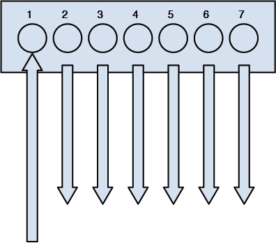
Repeater
A repeater is a device that is used to extend the distance of a network. Because the signal strength reduces over distance, a repeater should be used if you need to extend a network over a distance that is more than the recommended maximum for the cable type.
Bridge
Bridges are Layer 2 devices that filter traffic between network segments based on MAC addresses. Bridges prevent frames that are only going to the local network from being transmitted outside the local network. But they forward all network broadcasts. They can connect LANs that use different media, such as connecting a twisted pair (TP) network to a fiber optic network. To provide security, bridges should implement some form of Link layer encryption.
Switch
Switches are very similar to bridges; they are intelligent and operate at Layer 2 of the OSI model. We say they map to this layer because they make switching decisions based on MAC addresses, which reside at Layer 2. This process is called transparent bridging. Figure 4-21 shows this process.
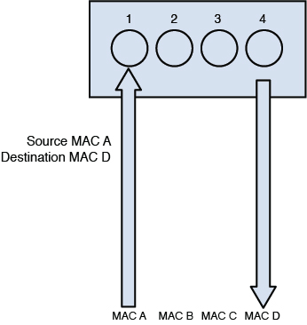
Switches improve performance over hubs because they eliminate collisions. Each switch port is in its own collision domain, whereas all ports of a hub are in the same collision domain. From a security standpoint, switches are more secure in that a sniffer connected to any single port will only be able to capture traffic destined for or originating from that port.
Switches are more expensive, faster, and harder to implement than bridges and hubs. Both bridges and switches provide better performance than hubs.
Some switches, however, are both routers and switches, and in that case we call them Layer 3 switches because they route and switch.
Layer 3 Versus Layer 4 Switching
Typically we map the switching process to Layer 2 of the OSI model because Layer 2 addresses are used to make frame-forwarding decisions. This doesn’t mean that a single physical device cannot be capable of both functions. A Layer 3 switch is such a device. It is a switch with the routing function also built in. It can both route and switch and can combine the two functions in an integrated way such that a single data stream can be routed when the first packet arrives and then the rest of the packets in the stream can be fast switched, resulting in better performance.
Layer 4 switches take this a step further by providing additional routing above Layer 3 by using the port numbers found in the Transport layer header to make routing decisions. The largest benefit of Layer 4 switching is the ability to prioritize data traffic by application, which means QoS can be defined for each user.
VLANs
Enterprise-level switches can be used to create virtual local area networks (VLANs). These are logical subdivisions of a switch that segregate ports from one another as if they were in different LANs. These VLANs can also span multiple switches, meaning that devices connected to switches in different parts of a network can be placed in the same VLAN regardless of physical location.
VLANs offer another way to add a layer of separation between sensitive devices and the rest of the network. For example, if only two devices should be able to connect to the HR server, the two devices and the HR server could be placed in a VLAN separate from the other VLANs. Traffic between VLANs can only occur through a router. Routers can be used to implement ACLs that control the traffic allowed between VLANs.
Router
Routers operate at Layer 3 (Network layer) when we are discussing the routing function in isolation. As previously discussed, certain devices can combine routing functionality with switching and Layer 4 filtering. However, because routing uses Layer 3 information (IP addresses) to make decisions, it is a Layer 3 function.
Routers use a routing table that tells the router in which direction to send traffic destined for a particular network. Although routers can be configured with routes to individual computers, typically they route toward networks, not individual computers. When the packet arrives at the router that is directly connected to the destination network, that particular router performs an ARP broadcast to learn the MAC address of the computer and send the packets as frames at Layer 2.
Routers perform an important security function because on them ACLs are typically configured. These are ordered sets of rules that control the traffic that is permitted or denied the use of a path through the router. These rules can operate at Layer 3, making these decisions on the basis of IP addresses, or at Layer 4 when only certain types of traffic are allowed. When this is done, the ACL typically references a port number of the service or application that is allowed or denied.
Boundary routers communicate with external hosts so that external hosts are able to connect to internal hosts. Internal routers communicate with internal hosts so that they can connect to other internal hosts. The security configuration of boundary routers is more vital because they should filter external traffic to prevent unwanted communication from reaching the internal network.
Gateway
The term gateway doesn’t refer to a particular device but rather to any device that performs some sort of translation or acts as a control point to entry and exit.
An example of a device performing as a gateway would be an email server. It receives email from all types of email servers (Exchange, IBM Notes, Micro Focus GroupWise) and performs any translation of formats that is necessary between these different implementations.
Another example would be a network access server (NAS) that controls access to a network. This would be considered a gateway in that all traffic might need to be authenticated before entry is allowed. This type of server might even examine the computers themselves for the latest security patches and updates before entry is allowed.
Firewalls
The network device that perhaps is most connected with the idea of security is the firewall. Firewalls can be software programs that are installed over server operating systems or they can be appliances that have their own operating system. In either case their job is to inspect and control the type of traffic allowed.
Firewalls can be discussed on the basis of their type and their architecture. They can also be physical devices or exist in a virtualized environment. This section looks at them from all angles.
Firewall Types
When we discuss types of firewalls, we are focusing on the differences in the way they operate. Some firewalls make a more thorough inspection of traffic than others. Usually there is tradeoff in the performance of the firewall and the type of inspection that it performs. A deep inspection of the contents of each packet results in the firewall having a detrimental effect on throughput, whereas a more cursory look at each packet has somewhat less of an impact on performance. It is for this reason we make our selections of what traffic to inspect wisely, keeping this tradeoff in mind.
Packet filtering firewalls are the least detrimental to throughput because they only inspect the header of the packet for allowed IP addresses or port numbers. Although even performing this function will slow traffic, it involves only looking at the beginning of the packet and making a quick allow or disallow decision.
Although packet filtering firewalls serve an important function, they cannot prevent many attack types. They cannot prevent IP spoofing, attacks that are specific to an application, attacks that depend on packet fragmentation, or attacks that take advantage of the TCP handshake. More advanced inspection firewall types are required to stop these attacks.
Stateful firewalls are those that are aware of the proper functioning of the TCP handshake, keep track of the state of all connections with respect to this process, and can recognize when packets are trying to enter the network that don’t make sense in the context of the TCP handshake. You might recall the discussion of how the TCP handshake occurs from the section “Transport Layer,” earlier in this chapter.
To review that process, a packet should never arrive at a firewall for delivery that has both the SYN flag and the ACK flag set unless it is part of an existing handshake process and it should be in response to a packet sent from inside the network with the SYN flag set. This is the type of packet that the stateful firewall would disallow. It also has the ability to recognize other attack types that attempt to misuse this process. It does this by maintaining a state table about all current connections and the status of each connection process. This allows it to recognize any traffic that doesn’t make sense with the current state of the connection. Of course, maintaining this table and referencing the table cause this firewall type to have more effect on performance than a packet filtering firewall.
Proxy firewalls actually stand between each connection from the outside to the inside and make the connection on behalf of the endpoints. Therefore there is no direct connection. The proxy firewall acts as a relay between the two endpoints. Proxy firewalls can operate at two different layers of the OSI model. Both are discussed shortly.
Circuit-level proxies operate at the Session layer (Layer 5) of the OSI model. They make decisions based on the protocol header and Session layer information. Because they do not do deep packet inspection (at Layer 7 or the Application layer), they are considered application-independent and can be used for wide ranges of Layer 7 protocol types.
A Socket Secure (SOCKS) firewall is an example of a circuit-level firewall. This requires a SOCKS client on the computers. Many vendors have integrated their software with SOCKS to make using this type of firewall easier. SOCKS routes network packets through a proxy server. SOCKS v5 added authentication to the process. A SOCKS firewall works at the Session layer (Layer 5).
Application-level proxies perform deep packet inspection. This type of firewall understands the details of the communication process at Layer 7 for the application of interest. An application-level firewall maintains a different proxy function for each protocol. For example, for HTTP the proxy will be able to read and filter traffic based on specific HTTP commands. Operating at this layer requires each packet to be completely opened and closed, making this firewall the most impactful on performance.
Dynamic packet filtering, rather than describing a different type of firewall, describes functionality that a firewall might or might not possess. When internal computers attempt to establish a session with a remote computer, it places both a source and destination port number in the packet. For example, if the computer is making a request of a web server, because HTTP uses port 80, the destination will be port 80.
The source computer selects the source port at random from the numbers available above the well-known port numbers, or above 1023. Because predicting what that random number will be is impossible, creating a firewall rule that anticipates and allows traffic back through the firewall on that random port is impossible. A dynamic packet filtering firewall will keep track of that source port and dynamically add a rule to the list to allow return traffic to that port.
A kernel proxy firewall is an example of a fifth-generation firewall. It inspects the packet at every layer of the OSI model but does not introduce the performance hit that an Application layer firewall will because it does this at the kernel layer. It also follows the proxy model in that it stands between the two systems and creates connections on their behalf.
Firewall Architecture
Whereas the type of firewall speaks to the internal operation of the firewall, the architecture refers to the way in which the firewall or firewalls are deployed in the network to form a system of protection. This section looks at the various ways firewalls can be deployed and what the names of these various configurations are.
Although bastion hosts are included in this discussion regarding firewalls, a bastion host might or might not be a firewall. The term actually refers to the position of a device. If it is exposed directly to the Internet or to any untrusted network, we call it a bastion host. All standard hardening procedures are especially important for these exposed devices. Any unnecessary services should be stopped, all unneeded ports should be closed, and all security patches must be up to date. These procedures are said to reduce the attack surface. If a bastion host is deployed, it is the only host on the internal network that is exposed to the Internet or untrusted networks. If the bastion host is deployed separately from the firewall, it is placed outside the firewall or on the public side of the demilitarized zone (DMZ). The bastion host filters all incoming traffic. Firewalls and routers can be configured to be bastion hosts.
A dual-homed firewall, also referred to as a dual-homed host, has two network interfaces via the installation of two NICs, each on a separate network. In many cases automatic routing between these interfaces is turned off. The firewall software allows or denies traffic between the two interfaces based on the firewall rules configured by the administrator. The danger of relying on a single dual-homed firewall is that there is a single point of failure. If this device is compromised, the network is also. If it suffers a denial-of-service (DoS) attack, no traffic will pass. Neither is a good situation.
In some cases a firewall may be multi-homed. One popular type is the three-legged firewall. This configuration has three interfaces: one connected to the untrusted network, one to the internal network, and one to the DMZ. A DMZ, also referred to as a screened subnet, is a portion of the network where systems are placed that will be accessed regularly from the untrusted network. These might be web servers or an email server, for example. The firewall can then be configured to control the traffic that flows between the three networks, being somewhat careful with traffic destined for the DMZ and then treating traffic to the internal network with much more suspicion.
Although the firewalls discussed thus far typically connect directly to the untrusted network (at least one interface does), a screened host is a firewall that is between the final router and the internal network. When traffic comes into the router and is forwarded to the firewall, it will be inspected before going into the internal network.
Taking this concept a step further is a screened subnet. In this case, two firewalls are used, and traffic must be inspected at both firewalls to enter the internal network. It is called a screened subnet because there will be a subnet between the two firewalls that can act as a DMZ for resources from the outside world.
In the real world, these various approaches are mixed and matched to meet requirements, so you might find elements of all these architectural concepts being applied to a specific situation.
Proxy Server
Proxy servers can be appliances or they can be software that is installed on a server operating system. These servers act like a proxy firewall in that they create the web connection between systems on their behalf, but they can typically allow and disallow traffic on a more granular basis. For example, a proxy server might allow the Sales group to go to certain websites while not allowing the Data Entry group access to these same sites. The functionality extends beyond HTTP to other traffic types, such as FTP and others.
Proxy servers can provide an additional beneficial function called web caching. When a proxy server is configured to provide web caching, it saves a copy of all web pages that have been delivered to internal computers in a web cache. If any user requests the same page later, the proxy server has a local copy and need not spend the time and effort to retrieve it from the Internet. This greatly improves web performance for frequently requested pages.
PBX
A private branch exchange (PBX) is a private telephone switch that resides on the customer premises. It has a direct connection to the telecommunication provider’s switch. It performs call routing within the internal phone system. This is how a company can have two “outside” lines but 50 internal phones. The call comes in on one of the two outside lines, and the PBX routes it to the proper extension. Sometimes the system converts analog to digital, but not always.
The security considerations with these devices revolve around their default configurations. They typically are configured with default administrator passwords that should be changed, and they often contain backdoor connections that can be used by vendor support personnel to connect in and help with problems. These backdoors are usually well known and should be disabled until they are needed.
Honeypot
Honeypots are systems that are configured to be attractive to hackers and lure them into spending time attacking them while information is gathered about the attack. In some cases entire networks called honeynets are attractively configured for this purpose. These types of approaches should only be undertaken by companies with the skill to properly deploy and monitor them.
Care should be taken that the honeypots and honeynets do not provide direct connections to any important systems. This prevents providing a jumping-off point to other areas of the network. The ultimate purpose of these systems is to divert attention from more valuable resources and to gather as much information about an attack as possible. A tarpit is a type of honeypot designed to provide a very slow connection to the hacker so that the attack can be analyzed.
IDS
An intrusion detection system (IDS) is a system responsible for detecting unauthorized access or attacks against systems and networks. It can verify, itemize, and characterize threats from outside and inside the network. Most IDSs are programmed to react certain ways in specific situations. Event notification and alerts are crucial to an IDS. They inform administrators and security professionals when and where attacks are detected.
The most common way to classify an IDS is based on its information source: network-based or host-based.
A network-based IDS (NIDS) is the most common IDS and monitors network traffic on a local network segment. To monitor traffic on the network segment, the NIC must be operating in promiscuous mode. An NIDS can only monitor the network traffic. It cannot monitor any internal activity that occurs within a system, such as an attack against a system that is carried out by logging on to the system’s local terminal. An NIDS is affected by a switched network because generally an NIDS only monitors a single network segment.
A host-based IDS (HIDS) monitors traffic on a single system. Its primary responsibility is to protect the system on which it is installed. An HIDS uses information from the operating system audit trails and system logs. The detection capabilities of an HIDS are limited by how complete the audit logs and system logs are.
IDS implementations are further divided into the following categories:
Signature-based: This type of IDS analyzes traffic and compares it to attack or state patterns, called signatures, that reside within the IDS database. It is also referred to as a misuse-detection system. Although this type of IDS is very popular, it can only recognize attacks as compared with its database and is only as effective as the signatures provided. Frequent updates are necessary. The two main types of signature-based IDSs are
Pattern-matching: The IDS compares traffic to a database of attack patterns. The IDS carries out specific steps when it detects traffic that matches an attack pattern.
Stateful-matching: The IDS records the initial operating system state. Any changes to the system state that specifically violate the defined rules result in an alert or notification being sent.
Anomaly-based: This type of IDS analyzes traffic and compares it to normal traffic to determine whether said traffic is a threat. It is also referred to as a behavior-based or profile-based system. The problem with this type of system is that any traffic outside of expected norms is reported, resulting in more false positives than signature-based systems. The three main types of anomaly-based IDSs are
Statistical anomaly-based: The IDS samples the live environment to record activities. The longer the IDS is in operation, the more accurate a profile that will be built. However, developing a profile that will not have a large number of false positives can be difficult and time-consuming. Thresholds for activity deviations are important in this IDS. Too low a threshold results in false positives, whereas too high a threshold results in false negatives.
Protocol anomaly-based: The IDS has knowledge of the protocols that it will monitor. A profile of normal usage is built and compared to activity.
Traffic anomaly-based: The IDS tracks traffic pattern changes. All future traffic patterns are compared to the sample. Changing the threshold will reduce the number of false positives or negatives. This type of filter is excellent for detecting unknown attacks, but user activity might not be static enough to effectively implement this system.
Rule- or heuristic-based: This type of IDS is an expert system that uses a knowledge base, inference engine, and rule-based programming. The knowledge is configured as rules. The data and traffic are analyzed, and the rules are applied to the analyzed traffic. The inference engine uses its intelligent software to “learn.” If characteristics of an attack are met, alerts or notifications trigger. This is often referred to as an IF/THEN or expert system.
An application-based IDS is a specialized IDS that analyzes transaction log files for a single application. This type of IDS is usually provided as part of the application or can be purchased as an add-on.
When implementing and managing IDSs, administrators must understand the difference between a false positive and a false negative. A false positive occurs when an IDS identifies an activity as an attack but the activity is acceptable behavior. A false negative state occurs when the IDS identifies an activity as acceptable when the activity is actually an attack. While a false positive is a false alarm, a false negative is a dangerous state since the security professional has no idea that an attack took place.
Tools that can complement an IDS include vulnerability analysis systems, honeypots, and padded cells. As described earlier, honeypots are systems that are configured with reduced security to entice attackers so that administrators can learn about attack techniques. Padded cells are special hosts to which an attacker is transferred during an attack.
IPS
An intrusion prevention system (IPS) is a system responsible for preventing attacks. When an attack begins, an IPS takes actions to prevent and contain the attack. An IPS can be network- or host-based, like an IDS. Although an IPS can be signature- or anomaly-based, it can also use a rate-based metric that analyzes the volume of traffic as well as the type of traffic.
In most cases, implementing an IPS is more costly than an IDS because of the added security of preventing attacks versus simply detecting attacks. In addition, running an IPS is more of an overall performance load than running an IDS.
Wireless Access Point
A wireless access point (AP) allows wireless devices to connect to a wired network using Wi-Fi or related standards. It operates at the Physical and Data Link layers (Layers 1 and 2). Wireless networks are discussed in detail earlier in this chapter.
Mobile Devices
Mobile devices—including laptops, tablets, smartphones, e-readers, and wearable technology devices—have quickly become the most widely used devices. An organization should adopt a formal mobile device security policy and a bring-your-own-device (BYOD) security policy if personal devices will be permitted. The organization may also want to consider deploying a network access control (NAC) server to ensure that any devices that join the network meet minimum security requirements and quarantine any devices that do not meet minimum security requirements.
NIST SP 800-124 Revision 1 provides guidelines for managing the security of mobile devices in the enterprise. According to NIST SP 800-124 Rev. 1, organizations should implement the following guidelines to improve the security of their mobile devices:
Organizations should have a mobile device security policy. It should define which types of the organization’s resources may be accessed via mobile devices, which types of mobile devices are permitted to access the organization’s resources, the degree of access that various classes of mobile devices may have—for example, organization-issued devices versus personally owned (BYOD) devices—and how provisioning should be handled. It should also cover how the organization’s centralized mobile device management servers are administered, how policies in those servers are updated, and all other requirements for mobile device management technologies. The mobile device security policy should be documented in the system security plan. To the extent feasible and appropriate, the mobile device security policy should be consistent with and complement security policy for non-mobile systems.
Organizations should develop system threat models for mobile devices and the resources that are accessed through the mobile devices. Mobile devices often need additional protection because their nature generally places them at higher exposure to threats than other client devices (for example, desktop and laptop devices only used within the organization’s facilities and on the organization’s networks). Before designing and deploying mobile device solutions, organizations should develop system threat models. Threat modeling helps organizations to identify security requirements and to design the mobile device solution to incorporate the controls needed to meet the security requirements. Threat modeling involves identifying resources of interest and the feasible threats, vulnerabilities, and security controls related to these resources, then quantifying the likelihood of successful attacks and their impacts, and finally analyzing this information to determine where security controls need to be improved or added.
Organizations deploying mobile devices should consider the merits of each provided security service, determine which services are needed for their environment, and then design and acquire one or more solutions that collectively provide the necessary services. Most organizations do not need all of the possible security services provided by mobile device solutions. Categories of services to be considered include the following:
General policy: Enforcing enterprise security policies on the mobile device, such as restricting access to hardware and software, managing wireless network interfaces, and automatically monitoring, detecting, and reporting when policy violations occur.
Data communication and storage: Supporting strongly encrypted data communications and data storage, wiping the device before reissuing it, and remotely wiping the device if it is lost or stolen and is at risk of having its data recovered by an untrusted party.
User and device authentication: Requiring device authentication and/or other authentication before accessing organization resources, resetting forgotten passwords remotely, automatically locking idle devices, and remotely locking devices suspected of being left unlocked in an unsecured location.
Applications: Restricting which app stores may be used and which applications may be installed, restricting the permissions assigned to each application, installing and updating applications, restricting the use of synchronization services, verifying digital signatures on applications, and distributing the organization’s applications from a dedicated mobile application store.
Organizations should implement and test a pilot of their mobile device solution before putting the solution into production. Aspects of the solution that should be evaluated for each type of mobile device include connectivity, protection, authentication, application functionality, solution management, logging, and performance. Another important consideration is the security of the mobile device implementation itself; at a minimum, all components should be updated with the latest patches and configured following sound security practices. Also, use of jailbroken or rooted mobile devices should be automatically detected when feasible. Finally, implementers should ensure that the mobile device solution does not unexpectedly “fall back” to default settings for interoperability or other reasons.
Organizations should fully secure each organization-issued mobile device before allowing a user to access it. This ensures a basic level of trust in the device before it is exposed to threats. For any already-deployed organization-issued mobile device with an unknown security profile (e.g., unmanaged device), organizations should fully secure them to a known good state (for example, through deployment and use of enterprise mobile device management technologies). Supplemental security controls should be deployed as risk merits, such as antivirus software and data loss prevention (DLP) technologies.
Organizations should regularly maintain mobile device security. Helpful operational processes for maintenance include checking for upgrades and patches, and acquiring, testing, and deploying them; ensuring that each mobile device infrastructure component has its clock synced to a common time source; reconfiguring access control features as needed; and detecting and documenting anomalies within the mobile device infrastructure, including unauthorized configuration changes to mobile devices. Other helpful maintenance processes are keeping an active inventory of each mobile device, its user, and its applications; revoking access to or deleting an application that has already been installed but has subsequently been assessed as too risky to use; and scrubbing sensitive data from mobile devices before reissuing them to other users. Also, organizations should periodically perform assessments to confirm that their mobile device policies, processes, and procedures are being followed properly. Assessment activities may be passive, such as reviewing logs, or active, such as performing vulnerability scans and penetration testing.
The main threats when dealing with mobile devices include
Lack of physical security controls
Use of untrusted mobile devices
Use of untrusted networks
Use of untrusted applications
Interaction with other systems
Use of untrusted content
Use of location services
NIST SP 800-124 Rev. 1 makes several recommendations for mobile devices. General policy restrictions of particular interest for mobile device security include the following:
Restrict user and application access to hardware, such as the digital camera, GPS, Bluetooth interface, USB interface, and removable storage.
Restrict user and application access to native OS services, such as the built-in web browser, email client, calendaring, contacts, application installation services, and so on.
Manage wireless network interfaces (Wi-Fi, Bluetooth, and so on).
Automatically monitor, detect, and report when policy violations occur, such as changes from the approved security configuration baseline, and automatically take action when possible and appropriate.
Limit or prevent access to enterprise services based on the mobile device’s operating system version (including whether the device has been rooted/jailbroken), vendor/brand, model, or mobile device management software client version (if applicable). Note that this information may be spoofable.
Data communication and storage restrictions for mobile device security include the following:
Strongly encrypt data communications between the mobile device and the organization.
Strongly encrypt stored data on both built-in storage and removable media storage.
Wipe the device (to scrub its stored data) before reissuing it to another user, retiring the device, and so on.
Remotely wipe the device (to scrub its stored data) if it is suspected that the device has been lost, stolen, or otherwise fallen into untrusted hands and is at risk of having its data recovered by an untrusted party.
A device often can also be configured to wipe itself after a certain number of incorrect authentication attempts.
User and device authentication restrictions for mobile device security include the following:
Require a device password/passcode and/or other authentication (e.g., token-based authentication, network-based device authentication, domain authentication) before accessing the organization’s resources.
If device account lockout is enabled or the device password/passcode is forgotten, an administrator can reset this remotely to restore access to the device.
Have the device automatically lock itself after it is idle for a period (e.g., 5 minutes).
Under the direction of an administrator, remotely lock the device if it is suspected that the device has been left in an unlocked state in an unsecured location.
Application restrictions for mobile device security include the following:
Restrict which app stores may be used.
Restrict which applications may be installed through whitelisting (preferable) or blacklisting.
Restrict the permissions (e.g., camera access, location access) assigned to each application.
Install, update, and remove applications. Safeguard the mechanisms used to perform these actions.
Restrict the use of operating system and application synchronization services (e.g., local device synchronization, remote synchronization services, and websites).
Verify digital signatures on applications to ensure that only applications from trusted entities are installed on the device and that code has not been modified.
Distribute the organization’s applications from a dedicated mobile application store.
For more information on mobile device security recommendations, download NIST SP 800-124 Rev. 1 from https://nvlpubs.nist.gov/nistpubs/SpecialPublications/NIST.SP.800-124r1.pdf.
Network Routing
Routing occurs at Layer 3 of the OSI model, which is also the layer at which IP operates and where the source and destination IP addresses are placed in the packet. Routers are devices that transfer traffic between systems in different IP networks. When computers are in different IP networks, they cannot communicate unless a router is available to route the packets to the other networks.
Routers keep information about the paths to other networks in a routing table. These tables can be populated several ways. Administrators manually enter these routes, or dynamic routing protocols allow the routers running the same protocol to exchange routing tables and routing information. Manual configuration, also called static routing, has the advantage of avoiding the additional traffic created by dynamic routing protocols and allows for precise control of routing behavior, but it requires manual intervention when link failures occur. Dynamic routing protocols create traffic but are able to react to link outages and reroute traffic without manual intervention.
From a security standpoint, routing protocols introduce the possibility that routing update traffic might be captured, allowing a hacker to gain valuable information about the layout of the network. Moreover, Cisco devices (perhaps the most widely used) also use a proprietary Layer 2 protocol by default called Cisco Discovery Protocol (CDP) that they use to inform each other about their capabilities. If the CDP packets are captured, additional information can be obtained that can be helpful to mapping the network in advance of an attack.
This section compares and contrasts routing protocols.
Distance Vector, Link State, or Hybrid Routing
Routing protocols have different capabilities and operational characteristics that impact when and where they are utilized. Routing protocols come in two basic types: interior and exterior. Interior routing protocols are used within an autonomous system, which is a network managed by one set of administrators, typically a single enterprise. Exterior routing protocols route traffic between systems or company networks. An example of this type of routing is what occurs on the Internet.
Routing protocols also can fall into three categories that describe their operations more than their scope: distance vector, link state, and hybrid (or advanced distance vector). The difference in these mostly revolves around the amount of traffic created and the method used to determine the best path out of possible paths to a network. The value used to make this decision is called a metric, and each has a different way of calculating the metric and thus determining the best path.
Distance vector protocols share their entire routing table with their neighboring routers on a schedule, thereby creating the most traffic of the three categories. They also use a metric called hop count. Hop count is simply the number of routers traversed to get to a network.
Link state protocols only share network changes (link outages and recoveries) with neighbors, thereby greatly reducing the amount of traffic generated. They also use a much more sophisticated metric that is based on many factors, such as the bandwidth of each link on the path and the congestion on each link. So when using one of these protocols, a path might be chosen as best even though it has more hops because the path chosen has better bandwidth, meaning less congestion.
Hybrid or advanced distance vector protocols exhibit characteristics of both types. EIGRP, discussed later in this section, is the only example of this type. In the past, EIGRP has been referred to as a hybrid protocol but in the last several years, Cisco (which created IGRP and EIGRP) has been calling this an advanced distance vector protocol, so you might see both terms used. In the following sections, several of the most common routing protocols are discussed briefly.
RIP
Routing Information Protocol (RIP) is a standards-based distance vector protocol that has two versions: RIPv1 and RIPv2. It operates at Layer 3 (Network layer). Both use hop count as a metric and share their entire routing tables every 30 seconds. Although RIP is the simplest to configure, it has a maximum hop count of 15, so it is only useful in very small networks. The biggest difference between the two versions is that RIPv1 can only perform classful routing, whereas RIPv2 can route in a network where CIDR has been implemented.
Unlike RIPv1, RIPv2 carries a subnet mask. It supports password authentication security and specifies the next hop.
OSPF
Open Shortest Path First (OSPF) is a standards-based link state protocol. It uses a metric called cost that is calculated based on many considerations. It operates at Layer 3 (Network layer). OSPF makes much more sophisticated routing decisions than a distance vector routing protocol such as RIP. To take full of advantage of OSPF, a much deeper knowledge of routing and OSPF itself is required. It can scale successfully to very large networks because it has no minimum hop count.
OSPFv2 allows routers to communicate with other routers regarding the routes they know. Link state advertisements (LSAs) are used to communicate the routes between the routers.
IGRP
Interior Gateway Routing Protocol (IGRP) is an obsolete classful Cisco-proprietary routing protocol that you will not likely see in the real world because of its inability to operate in an environment where CIDR has been implemented. It has been replaced with the classless version Enhanced IGRP (EIGRP) discussed next.
EIGRP
Enhanced IGRP (EIGRP) is a classless Cisco-proprietary routing protocol that is considered a hybrid or advanced distance vector protocol. It exhibits some characteristics of both link state and distance vector operations. It also has no limitations on hop count and is much simpler to implement than OSPF. It does, however, require that all routers be Cisco.
VRRP
When a router goes down, all hosts that use that router for routing will be unable to send traffic to other networks. Virtual Router Redundancy Protocol (VRRP) is not really a routing protocol but rather is used to provide multiple gateways to clients for fault tolerance in the case of a router going down. All hosts in a network are set with the IP address of the virtual router as their default gateway. Multiple physical routers are mapped to this address so there will be an available router even if one goes down.
IS-IS
Intermediate System to Intermediate System (IS-IS) is a complex interior routing protocol that is based on OSI protocols rather than IP. It is a link state protocol. The TCP/IP implementation is called Integrated IS-IS. OSPF has more functionality, but IS-IS creates less traffic than OSPF and is much less widely implemented than OSPF.
BGP
Border Gateway Protocol (BGP) is an exterior routing protocol considered to be a path vector protocol. It routes between autonomous systems (ASs) or gateway hosts and is used on the Internet. It has a rich set of attributes that can be manipulated by administrators to control path selection and to control the exact way in which traffic enters and exits the AS. However, it is one of the most complex to understand and configure. BGP is an Application layer (Layer 7) protocol.
Transmission Media
The transmission media used on a network is the cabling that is used to transmit network traffic. Each of the different transmission media has a maximum speed, maximum distance, different security issues, and different environment. In this section we discuss the cabling, network topologies, network technologies, and WAN technologies that are covered in the CISSP exam.
Cabling
Cabling resides at the physical layer of the OSI model and simply provides a medium on which data can be transferred. The vast majority of data is transferred across cables of various types, including coaxial, fiber optic, and twisted pair. Some of these cables represent the data in terms of electrical voltages, whereas fiber cables manipulate light to represent the data. This section discusses each type.
You can compare cables to one another using several criteria. One of the criteria that is important with networking is the cable’s susceptibility to attenuation. Attenuation occurs when the signal meets resistance as it travels through the cable. This weakens the signal, and at some point (different in each cable type), the signal is no longer strong enough to be read properly at the destination. For this reason, all cables have a maximum length. This is true regardless of whether the cable is fiber optic or electrical.
Another important point of comparison between cable types is their data rate, which describes how much data can be sent through the cable per second. This area has seen great improvement over the years, going from rates of 10 Mbps in a LAN to 1000 Mbps and even 10 Gbps in today’s networks (and even higher rates in data centers).
Another consideration when selecting a cable type is the ease of installation. Some cable types are easier than others to install, and fiber optic cabling requires a special skill set to install, raising its price of installation.
Finally (and most importantly for our discussion) is the security of the cable. Cables can leak or radiate information. Cables can also be tapped into by hackers if they have physical access to them. Just as the cable types can vary in allowable length and capacity, they can also vary in their susceptibility to these types of data losses.
Coaxial
One of the earliest cable types to be used for networking was coaxial, the same basic type of cable that brought cable TV to millions of homes. Although coaxial cabling is still used, due to its low capacity and the adoption of other cable types, its use is almost obsolete now in LANs.
Coaxial cabling comes in two types or thicknesses. The thicker type, called Thicknet, has an official name of 10Base5. This naming system, used for other cable types as well, imparts several facts about the cable. In the case of 10Base5, it means that it is capable of transferring 10 Mbps and can go roughly 1,640 feet. Thicknet uses two types of connectors: a vampire tap (named thusly because it has a spike that pierces the cable) and N-connectors.
Thinnet or 10Base2 also operates at 10 Mbps. Although when it was named it was anticipated to be capable of running 200 feet, this was later reduced to 185 feet. Both types are used in a bus topology (more on topologies in the section “Network Topologies,” later in this chapter). Thinnet uses two types of connectors: BNC connectors and T-connectors.
Coaxial has an outer cylindrical covering that surrounds either a solid core wire (Thicknet) or a braided core (Thinnet). This type of cabling has been replaced over time with more capable twisted-pair and fiber optic cabling. Coaxial cabling can be tapped, so physical access to this cabling should be restricted or prevented if possible. It should be out of sight if it is used. Figure 4-22 shows the structure of a coaxial cable.
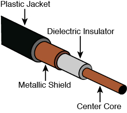
Another security problem with coax in a bus topology is that it is broadcast-based, which means a sniffer attached anywhere in the network can capture all traffic. In switched networks (more on that topic earlier in this chapter, in the section “Network Devices”), this is not a consideration.
Twisted Pair
The most common type of network cabling found today is called twisted-pair cabling. It is called this because inside the cable are four pairs of smaller wires that are braided or twisted. This twisting is designed to eliminate a phenomenon called crosstalk, which occurs when wires that are inside a cable interfere with one another. The number of wire pairs that are used depends on the implementation. In some implementations, only two pairs are used, and in others all four wire pairs are used. Figure 4-23 shows the structure of a twisted-pair cable.

Twisted-pair cabling comes in shielded (STP) and unshielded (UTP) versions. Nothing is gained from the shielding except protection from radio frequency interference (RFI) and electromagnetic interference (EMI). RFI is interference from radio sources in the area, whereas EMI is interference from power lines. A common type of EMI is called common mode noise, which is interference that appears on both signal leads (signal and circuit return) or the terminals of a measuring circuit and ground. If neither EMI nor RFI is a problem, nothing is gained by using STP, and it costs more.
The same naming system used with coaxial and fiber is used with twisted pair. The following are the major types of twisted pair you will encounter:
10BaseT: Operates at 10 Mbps
100BaseT: Also called Fast Ethernet; operates at 100 Mbps
1000BaseT: Also called Gigabit Ethernet; operates at 1000 Mbps
10GbaseT: Operates at 10 Gbps
Twisted-pair cabling comes in various capabilities and is rated in categories. Table 4-8 lists the major types and their characteristics. Regardless of the category, twisted-pair cabling can be run about 100 meters before attenuation degrades the signal.
Table 4-8 Twisted-Pair Categories
Name |
Maximum Transmission Speed |
|---|---|
Cat3 |
10 Mbps |
Cat4 |
16 Mbps |
Cat5 |
100 Mbps |
Cat5e |
100 Mbps |
Cat6 |
1 Gbps |
Cat6a |
10 Gbps |
Cat7 |
10 Gbps |
Cat7a |
10 Gbps; 40 Gbps (50 meters); 100 Gbps (15 meters) |
Fiber Optic
Fiber optic cabling uses a source of light that shoots down an inner glass or plastic core of the cable. This core is covered by cladding that causes light to be confined to the core of the fiber. It is often used as the network backbone and may even be seen in home Internet, phone, and cable TV implementations. Figure 4-24 shows the structure of a fiber optic cable.
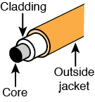
Fiber optic cabling manipulates light such that it can be interpreted as ones and zeros. Because it is not electrically based, it is totally impervious to EMI, RFI, and crosstalk. Moreover, although not impossible, tapping or eavesdropping on a fiber cable is much more difficult. In most cases, attempting to tap into it results in a failure of the cable, which then becomes quite apparent to all.
Fiber comes in single- and multi-mode formats. The single mode uses a single beam of light provided by a laser, goes the further of the two, and is the most expensive. Multi-mode uses several beams of light at the same time, uses LEDs, will not go as far, and is less expensive. Either type goes much further than electrical cabling in a single run and also typically provides more capacity. Fiber cabling has its drawbacks, however. It is the most expensive to purchase and the most expensive to install. Table 4-9 shows some selected fiber specifications and their theoretical maximum distances.
Table 4-9 Selected Fiber Specifications
Standard |
Distance |
|---|---|
100Base-FX |
Maximum length is 400 meters for half-duplex connections (to ensure collisions are detected) or 2 kilometers for full-duplex |
1000Base-SX |
550 meters |
1000Base-LX |
Multi-mode fiber (up to 550 meters) or single-mode fiber (up to 2 kilometers; can be optimized for longer distances, up to 10 kilometers) |
10Gbase-LR |
10 kilometers |
10Gbase-ER |
40 kilometers |
Network Topologies
Networks can be described by their logical topology (the data path used) and by their physical topology (the way in which devices are connected to one another). In most cases (but not all) the logical topology and the physical topology will be the same. This section discusses both logical and physical network topologies.
Ring
A physical ring topology is one in which the devices are daisy-chained one to another in a circle or ring. If the network is also a logical ring, the data circles the ring from one device to another. Two technologies use this topology, FDDI and Token Ring. Both these technologies are discussed in detail in the section “Network Technologies.” Figure 4-25 shows a typical ring topology.
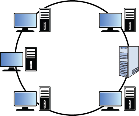
One of the drawbacks of the ring topology is that if a break occurs in the line, all systems will be affected as the ring will be broken. As you will see in the section “Network Technologies,” an FDDI network addresses this issue with a double ring for fault tolerance.
Bus
The bus topology was the earliest Ethernet topology used. In this topology, all devices are connected to a single line that has two definitive endpoints. The network does not loop back and form a ring. This topology is broadcast-based, which can be a security issue in that a sniffer or protocol analyzer connected at any point in the network will be capable of capturing all traffic. From a fault tolerance standpoint, the bus topology suffers the same danger as a ring. If a break occurs anywhere in the line, all devices are affected. Moreover, a requirement specific to this topology is that each end of the bus must be terminated. This prevents signals from “bouncing” back on the line causing collisions. (More on collisions later, but collisions require the collided packets to be sent again, lowering overall throughput.) If this termination is not done properly, the network will not function correctly. Figure 4-26 shows a bus topology.

Star
The star topology is the most common in use today. In this topology, all devices are connected to a central device (either a hub or a switch). One of the advantages of this topology is that if a connection to any single device breaks, only that device is affected and no others. The downside of this topology is that a single point of failure (the hub or switch) exists. If the hub or switch fails, all devices are affected. Figure 4-27 shows a star topology.
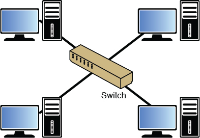
Mesh
Although the mesh topology is the most fault tolerant of any discussed thus far, it is also the most expensive to deploy. In this topology, all devices are connected to all other devices. This provides complete fault tolerance but also requires multiple interfaces and cables on each device. For that reason, it is deployed only in rare circumstances where such an expense is warranted. Figure 4-28 shows a mesh topology.
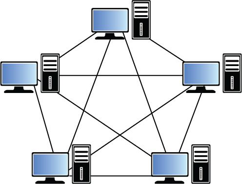
Hybrid
In many cases an organization’s network is a combination of these network topologies, or a hybrid network. For example, one section might be a star that connects to a bus network or a ring network. Figure 4-29 shows an example of a hybrid network.

Network Technologies
Just as a network can be connected in various topologies, different technologies have been implemented over the years that run over those topologies. These technologies operate at Layer 2 of the OSI model, and their details of operation are specified in various standards by the Institute of Electrical and Electronics Engineers (IEEE). Some of these technologies are designed for LAN applications, whereas others are meant to be used in a WAN. In this section, we look at the main LAN technologies and some of the processes that these technologies use to arbitrate access to the network.
Ethernet 802.3
The IEEE specified the details of Ethernet in the 802.3 standard. Prior to this standardization, Ethernet existed in several earlier forms, the most common of which was called Ethernet II or DIX Ethernet (DIX stands for the three companies that collaborated on its creation, DEC, Intel, and Xerox).
In the section on the OSI model, you learned that the PDU created at Layer 2 is called a frame. Because Ethernet is a Layer 2 protocol, we refer to the individual Ethernet packets as frames. There are small differences in the frame structures of Ethernet II and 802.3, although they are compatible in the same network. Figure 4-30 shows a comparison of the two frames. The significant difference is that during the IEEE standardization process, the Ethernet Type field was changed to a (data) length field in the new 802.3 standard. For purposes of identifying the data type, another field called the 802.2 header was inserted to contain that information.
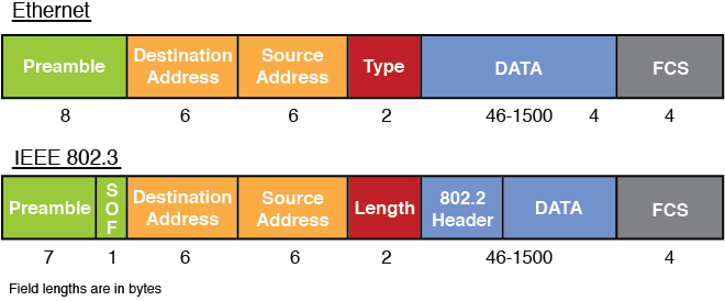
Ethernet has been implemented on coaxial, fiber, and twisted-pair wiring. Table 4-10 lists some of the more common Ethernet implementations.
Table 4-10 Ethernet Implementations
Ethernet Type |
Cable Type |
Speed |
|---|---|---|
10Base2 |
Coaxial |
10 Mbps |
10Base5 |
Coaxial |
10 Mbps |
10BaseT |
Twisted pair |
10 Mbps |
100BaseTX |
Twisted pair |
100 Mbps |
1000BaseT |
Twisted pair |
1000 Mbps |
1000BaseX |
Fiber |
1000 Mbps |
10GbaseT |
Twisted pair |
10 Gbps |
Note
Despite the fact that 1000BaseT and 1000BaseX are faster, 100BaseTX is called Fast Ethernet. Also, both 1000BaseT and 1000BaseX are usually referred to as Gigabit Ethernet.
Ethernet calls for devices to share the medium on a frame-by-frame basis. It arbitrates access to the media using a process called Carrier Sense Multiple Access/Collision Detection (CSMA/CD). This process is discussed in detail in the section “CSMA/CD Versus CSMA/CA,” where it is contrasted with the method used in 802.11 wireless networks.
Token Ring 802.5
Ethernet is the most common Layer 2 protocol, but it has not always been that way. An example of a proprietary Layer 2 protocol that enjoyed some small success is IBM Token Ring. This protocol operates using specific IBM connective devices and cables, and the nodes must have Token Ring network cards installed. It can operate at 16 Mbps, which at the time of its release was impressive, but the proprietary nature of the equipment and the soon-to-be faster Ethernet caused Token Ring to fall from favor.
As mentioned earlier, in most cases the physical network topology is the same as the logical topology. Token Ring is the exception to that general rule. It is logically a ring and physically a star. It is a star in that all devices are connected to a central device called a media access unit (MAU), but the ring is formed in the MAU, and when you investigate the flow of the data, it goes from one device to another in a ring design by entering and exiting each port of the MAU, as shown in Figure 4-31.
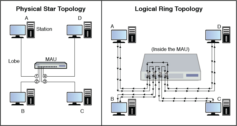
FDDI
Another Layer 2 protocol that uses a ring topology is Fiber Distributed Data Interface (FDDI). Unlike Token Ring, it is both a physical and a logical ring. It is actually a double ring, each going in a different direction to provide fault tolerance. It also is implemented with fiber cabling. In many cases it is used for a network backbone and is then connected to other network types, such as Ethernet, forming a hybrid network. It is also used in metropolitan area networks (MANs) because it can be deployed up to 100 kilometers.
Figure 4-32 shows an example of an FDDI ring.

Contention Methods
Regardless of the Layer 2 protocol in use, there must be some method used to arbitrate the use of the shared media. Four basic processes have been employed to act as the traffic cop, so to speak:
CSMA/CD
CSMA/CA
Token passing
Polling
This section compares and contrasts each and provides examples of technologies that use each.
CSMA/CD Versus CSMA/CA
To appreciate CSMA/CD and CSMA/CA, you must understand the concept of collisions and collision domains in a shared network medium. Collisions occur when two devices send a frame at the same time causing the frames and their underlying electrical signals to collide on the wire. When this occurs, both signals and the frames they represent are destroyed or at the very least corrupted such that they are discarded when they reach the destination. Frame corruption or disposal causes both devices to resend the frames, resulting in a drop in overall throughput.
Collision Domains
A collision domain is any segment of the network where the possibility exists for two or more devices’ signals to collide. In a bus topology, that would constitute the entire network because the entire bus is a shared medium. In a star topology, the scope of the collision domain or domains depends on the central connecting device. Central connecting devices include hubs and switches. Hubs and switches are discussed more fully in the section “Network Devices,” but their differences with respect to collision domains need to be discussed here.
A hub is an unintelligent junction box into which all devices plug. All the ports in the hub are in the same collision domain because when a hub receives a frame, the hub broadcasts the frame out all ports. So logically, the network is still a bus.
A star topology with a switch in the center does not operate this way. A switch has the intelligence to record the MAC address of each device on every port. After all the devices’ MAC addresses are recorded, the switch sends a frame only to the port on which the destination device resides. Because each device’s traffic is then segregated from any other device’s traffic, each device is considered to be in its own collision domain.
This segregation provided by switches has both performance and security benefits. From a performance perspective, it greatly reduces the number of collisions, thereby significantly increasing overall throughput in the network. From a security standpoint, it means that a sniffer connected to a port in the switch will only capture traffic destined for that port, not all traffic. Compare this security to a hub-centric network. When a hub is in the center of a star network, a sniffer will capture all traffic regardless of the port to which it is connected because all ports are in the same collision domain.
In Figure 4-33, a switch has several devices and a hub connected to it with each collision domain marked to show how the two devices create collision domains. Note that each port on the switch is a collision domain, whereas the entire hub is a single collision domain.

CSMA/CD
In 802.3 networks, a mechanism called Carrier Sense Multiple Access/Collision Detection (CSMA/CD) is used when a shared medium is in use to recover from inevitable collisions. This process is a step-by-step mechanism that each station follows every time it needs to send a single frame. The steps to the process are as follows:
When a device needs to transmit, it checks the wire for existing traffic. This process is called carrier sense.
If the wire is clear, the device transmits and continues to perform carrier sense.
If a collision is detected, both devices issue a jam signal to all the other devices, which indicates to them to not transmit. Then both devices increment a retransmission counter. This is a cumulative total of the number of times this frame has been transmitted and a collision occurred. There is a maximum number at which it aborts the transmission of the frame.
Both devices calculate a random amount of time (called a random back-off) and wait that amount of time before transmitting again.
In most cases because both devices choose random amounts of time to wait, another collision will not occur. If it does, the procedure repeats.
CSMA/CA
In 802.11 wireless networks, CSMA/CD cannot be used as an arbitration method because unlike when using bounded media, the devices cannot detect a collision. The method used is called Carrier Sense Multiple Access/Collision Avoidance (CSMA/CA). It is a much more laborious process because each station must acknowledge each frame that is transmitted.
The “Wireless Networks” section covers 802.11 network operations in more detail, but for the purposes of understanding CSMA/CA we must at least lay some groundwork. The typical wireless network contains an access point (AP) and at least one or more wireless stations. In this type of network (called an Infrastructure mode wireless network), traffic never traverses directly between stations but is always relayed through the AP. The steps in CSMA/CA are as follows:
Station A has a frame to send to Station B. It checks for traffic in two ways. First, it performs carrier sense, which means it listens to see whether any radio waves are being received on its transmitter. Second, after the transmission is sent, it will continue to monitor the network for possible collisions.
If traffic is being transmitted, Station A decrements an internal countdown mechanism called the random back-off algorithm. This counter will have started counting down after the last time this station was allowed to transmit. All stations will be counting down their own individual timers. When a station’s timer expires, it is allowed to send.
If Station A performs carrier sense, there is no traffic and its timer hits zero, it sends the frame.
The frame goes to the AP.
The AP sends an acknowledgment back to Station A. Until that acknowledgment is received by Station A, all other stations must remain silent. For each frame that AP needs to relay, it must wait its turn to send using the same mechanism as the stations.
When its turn comes up in the cache queue, the frame from Station A is relayed to Station B.
Station B sends an acknowledgment back to the AP. Until that acknowledgment is received by the AP, all other stations must remain silent.
As you can see, these processes create a lot of overhead but are required to prevent collisions in a wireless network.
Token Passing
Both FDDI and Token Ring networks use a process called token passing. In this process, a special packet called a token is passed around the network. A station cannot send until the token comes around and is empty. Using this process, no collisions occur because two devices are never allowed to send at the same time. The problem with this process is that the possibility exists for a single device to gain control of the token and monopolize the network.
Polling
The final contention method to discuss is polling. In this system, a primary device polls each other device to see whether it needs to transmit. In this way, each device gets a transmit opportunity. This method is common in the mainframe environment.
WAN Technologies
Many different technologies have evolved for delivering WAN access to a LAN. They differ in capacity, availability, and, of course, cost. This section compares the various technologies.
T Lines
T-carriers are dedicated lines to which the subscriber has private access and does not share with another customer. Customers can purchase an entire T1, or they can purchase a part of a T1 called a fractional T1. T1 lines consist of 24 channels, each capable of 64 Kbps. This means a T1 has a total capacity of 1.544 Mbps. The T1 is split into channels through a process called time division multiplexing (TDM).
The drawback of a T1 is that the customer is buying the full capacity of the number of channels purchased, and any capacity left unused is wasted. This inflexibility and the high cost have made this option less appealing than it was at one time. The cost is a function of not only the number of channels but the distance of the line as well.
T-carriers also come in larger increments as well. Table 4-11 shows a summary of T-carriers and their capacity.
Table 4-11 T-Carriers
Carrier |
Number of Channels |
Speed (Mbps) |
|---|---|---|
Fractional |
1 |
0.064 |
T1 |
24 |
1.544 |
T2 |
96 |
6.312 |
T3 |
672 |
44.736 |
T4 |
4032 |
274.176 |
T5 |
5760 |
400.352 |
E Lines
In Europe, a similar technology to T-carrier lines exists called E-carriers. With this technology, 30 channels are bundled rather than 24. These technologies are not compatible, and the available sizes are a bit different. Table 4-12 shows some selected increments of E-carriers.
Table 4-12 E-Carriers
Signal |
Rate |
|---|---|
E0 |
64 Kbps |
E1 |
2.048 Mbps |
E2 |
8.448 Mbps |
E3 |
34.368 Mbps |
E4 |
139.264 Mbps |
E5 |
565.148 Mbps |
OC Lines (SONET)
Synchronous Optical Networking (SONET) user fiber-based links that operate over lines measured in optical carrier (OC) transmission rates. These lines are defined by an integer value of the basic unit of rate. The basic OC-1 rate is 55.84 Mbps, and all other rates are multiples of that. For example, an OC-3 yields 155.52 Mbps. Table 4-13 shows some of these rates. Smaller increments might be used by a company, whereas the larger pipes would be used by a service provider.
Table 4-13 Carrier Rates
Optical Carrier |
Speed |
|---|---|
OC-3 |
155 Mbps |
OC-12 |
622 Mbps |
OC-48 |
2.5 Gbps |
OC-192 |
9.6 Gbps |
CSU/DSU
A discussion of WAN connections would not be complete without discussing a device that many customers connect to for their WAN connection. A channel service unit/data service unit (CSU/DSU) connects a LAN to a WAN. This device performs a translation of the information from a format that is acceptable on the LAN to one that can be transmitted over the WAN connection.
The CSU/DSU is considered a data communications equipment (DCE) device, and it provides an interface for the router, which is considered a data terminal equipment (DTE) device. The CSU/DSU will most likely be owned by the telco, but not always, and in some cases this functionality might be built into the interface of the router, making a separate device unnecessary.
Circuit-Switching Versus Packet-Switching
On the topic of WAN connections, discussing the types of networks that these connections might pass through is also helpful. Some are circuit-switched, whereas others are packet-switched. Circuit-switching networks (such as the telephone) establish a set path to the destination and only use that path for the entire communication. It results in a predictable operation with fixed delays. These networks usually carry voice-oriented traffic.
Packet-switching networks (such as the Internet or a LAN) establish an optimal path-per-packet. This means each packet might go a different route to get to the destination. The traffic on these networks experiences performance bursts, and the amount of delay can vary widely. These types of networks usually carry data-oriented traffic.
Frame Relay
Frame Relay is a Layer 2 protocol used for WAN connections. Therefore, when Ethernet traffic must traverse a Frame Relay link, the Layer 2 header of the packet will be completely re-created to conform to Frame Relay. When the Frame Relay frame arrives at the destination, a new Ethernet Layer 2 header will be placed on the packet for that portion of the network.
When Frame Relay connections are provisioned, the customer pays for a minimum amount of bandwidth called the Committed Information Rate (CIR). That will be the floor of performance. However, because Frame Relay is a packet-switched network using Frame Relay switches, the actual performance will vary based on conditions. Customers are sharing the network rather than having a dedicated line, such as a T1 or Integrated Services Digital Network (ISDN) line. So in many cases the actual performance will exceed the CIR.
ATM
Asynchronous Transfer Mode (ATM) is a cell-switching technology. It transfers fixed-size cells of 53 bytes rather than packets, and after a path is established, it uses the same path for the entire communication. The use of a fixed path makes performance more predictable, making it a good option for voice and video, which need such predictability. Where IP networks depend on the source and destination devices to ensure data is properly transmitted, this responsibility falls on the shoulders of the devices between the two in the ATM world.
ATM is used mostly by carriers and service providers for their backbones, but some companies have implemented their own ATM backbones and ATM switches. This allows them to make an ATM connection to the carrier, which can save money over a connection with a T link because the ATM connection cost will be based on usage, unlike the fixed cost of the T1.
X.25
X.25 is somewhat like Frame Relay in that traffic moves through a packet-switching network. It charges by bandwidth used. The data is divided into 128-byte High-Level Data Link Control (HDLC) frames. It is, however, an older technology created in a time when noisy transmission lines were a big concern. Therefore, it has many error-checking mechanisms built in that make it very inefficient.
Switched Multimegabit Data Service
Switched Multimegabit Data Service (SMDS) is a connectionless, packet-switched technology that communicates across an established public network. It has been largely repacked with other WAN technologies. It can provide LAN-like performance to a WAN. It’s generally delivered over a SONET ring with a maximum effective service radius of around 30 miles.
Point-to-Point Protocol
Point-to-Point-Protocol (PPP) is a Layer 2 protocol that performs framing and encapsulation of data across point-to-point connections. These are connections to the ISP where only the customer device and the ISP device reside on either end. It can encapsulate a number of different LAN protocols such as TCP/IP. It does this by using a Network Core Protocol (NCP) for each of the LAN protocols in use.
Along with the use of multiple NCPs, it uses a single Link Control Protocol (LCP) to establish the connection. PPP provides the ability to authenticate the connection between the devices using either Password Authentication Protocol (PAP) or Challenge Handshake Authentication Protocol (CHAP). Whereas PAP transmits the credentials in cleartext, CHAP does not send the credentials across the line and is much safer.
High-Speed Serial Interface
High-Speed Serial Interface (HSSI) is one of the many physical implementations of a serial interface. Because these interfaces exist on devices, they are considered to operate at Layer 1 of the OSI model. The Physical layer is the layer that is concerned with the signaling of the message and the interface between the sender or receiver and the medium. Examples of other serial interfaces are
X.25
V.35
X.21
The HSSI interface is found on both routers and multiplexers and provides a connection to services such as Frame Relay and ATM. It operates at speeds up to 52 Mbps.
PSTN (POTS, PBX)
Probably the least attractive WAN connection available, at least from a performance standpoint, is the public switched telephone network (PSTN). Also referred to as the plain old telephone service (POTS), this is the circuit-switched network that has been used for analog phone service for years and is now mostly a digital operation.
This network can be utilized using modems for an analog line or with ISDN for digital phone lines. Both these options are discussed in more detail in the section “Remote Connection Technologies” because that is their main use. In some cases these connections might be used between offices but, due to the poor performance, typically only as a backup solution in case a more capable option fails. These connections must be established each time they are used as opposed to “always on” solutions, such as cable or DSL.
PBX devices were discussed in the earlier section “Network Devices.”
VoIP
Although voice over the PSTN is circuit-switched, voice can also be encapsulated in packets and sent across packet-switching networks. When this is done over an IP network, it is called Voice over IP (VoIP). Where circuit-switching networks use the Signaling System 7 (SS7) protocol to set up, control, and disconnect a call, VoIP uses Session Initiation Protocol (SIP) to break up the call sessions. In VoIP implementations, QoS is implemented to ensure that certain traffic (especially voice) is given preferential treatment over the network.
SIP is an Application layer protocol that can operate over either TCP or UDP. Addressing is in terms of IP addresses, and the voice traffic uses the same network used for regular data. Because latency is always possible on these networks, protocols have been implemented to reduce the impact as this type of traffic is much more affected by delay. Applications such as voice and video need to have protocols and devices that can provide an isochronous network. Isochronous networks guarantee continuous bandwidth without interruption. They do not use an internal clock source or start and stop bits. All bits are of equal importance and are anticipated to occur at regular intervals.
VoIP can be secured by taking the following measures:
Create a separate VLAN or subnet for the IP phones and prevent access to this VLAN by other computers.
Deploy a VoIP-aware firewall at the perimeter.
Ensure that all passwords related to VoIP are strong.
Secure the Network layer with IPsec.
Network Access Control Devices
Network access control (NAC) is a service that goes beyond authentication of the user and includes an examination of the state of the computer the user is introducing to the network when making a remote access or VPN connection to the network.
The Cisco world calls these services Network Admission Control, and the Microsoft world calls them Network Access Protection (NAP). Regardless of the term used, the goals of the features are the same: to examine all devices requesting network access for malware, missing security updates, and any other security issues the devices could potentially introduce to the network.
The steps that occur in Microsoft NAP are shown in Figure 4-34. The health state of the device requesting access is collected and sent to the Network Policy Server (NPS), where the state is compared to requirements. If requirements are met, access is granted.
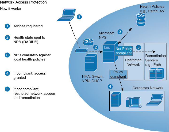
These are the limitations of using NAC or NAP:
They work well for company-managed computers but less so for guests.
They tend to react only to known threats and not new threats.
The return on investment is still unproven.
Some implementations involve confusing configuration.
Quarantine/Remediation
If you examine step 5 in the process shown in Figure 4-34, you see that a device that fails examination is placed in a restricted network until it can be remediated. A remediation server addresses the problems discovered on the device. It may remove the malware, install missing operating system updates, or update virus definitions. Once the remediation process is complete, the device is granted full access to the network.
Firewalls/Proxies
Firewalls and proxies can be used as part of NAC deployment. Firewalls enforce security rules by filtering incoming traffic by source address, destination address, or service. It is important that the rules be configured correctly to ensure that access to the network is not granted to malicious traffic or users. Proxies act as mediators between trusted and untrusted clients or servers. When proxies are deployed, it appears that all packets sent to the untrusted clients or servers originate with the proxies, thereby allowing all internal hosts to hide behind one public IP address.
Note
Firewalls and proxies are discussed in more detail earlier in this chapter, in the “Hardware” section.
Endpoint Security
Endpoint security is a field of security that attempts to protect individual systems in a network by staying in constant contact with these individual systems from a central location. It typically works on a client/server model in that each system will have software that communicates with the software on the central server. The functionality provided can vary.
In its simplest form, this includes monitoring and automatic updating and configuration of security patches and personal firewall settings. In more advanced systems, it might include an examination of the system each time it connects to the network. This examination would ensure that all security patches are up to date, and in even more advanced scenarios it could automatically provide remediation to the computer. In either case the computer would not be allowed to connect to the network until the problem is resolved, either manually or automatically. Other measures include using device or drive encryption, enabling remote management capabilities (such as remote wiping and remote location), and implementing device ownership policies and agreements so that the organization can manage or seize the device.
NIST SP 800-128 discusses implementing endpoint protection platforms (EPPs). According to NIST SP 800-128, personal computers are a fundamental part of any organization’s information system. They are an important source of connecting end users to networks and information systems, and are also a major source of vulnerabilities and a frequent target of attackers looking to penetrate a network. User behavior is difficult to control and hard to predict, and user actions, whether it is clicking on a link that executes malware or changing a security setting to improve the usability of their PC, frequently allow exploitation of vulnerabilities. Commercial vendors offer a variety of products to improve security at the “endpoints” of a network. These EPPs include
Anti-malware: Anti-malware applications are part of the common secure configurations for system components. Anti-malware software employs a wide range of signatures and detection schemes, automatically updates signatures, disallows modification by users, runs scans on a frequently scheduled basis, has an auto-protect feature set to scan automatically when a user action is performed (e.g., opening or copying a file), and may provide protection from zero-day attacks. For platforms for which anti-malware software is not available, other forms of anti-malware such as rootkit detectors may be employed.
Personal firewalls: Personal firewalls provide a wide range of protection for host machines including restriction on ports and services, control against malicious programs executing on the host, control of removable devices such as USB devices, and auditing and logging capability.
Host-based intrusion detection and prevention system (IDPS): Host-based IDPS is an application that monitors the characteristics of a single host and the events occurring within that host to identify and stop suspicious activity. This is distinguished from network-based IDPS, which is an intrusion detection and prevention system that monitors network traffic for particular network segments or devices and analyzes the network and application protocol activity to identify and stop suspicious activity.
Restrict the use of mobile code: Organizations exercise caution in allowing the use of “mobile code” such as ActiveX, Java, and JavaScript. An attacker can easily attach a script to a URL in a web page or email that, when clicked, will execute malicious code within the computer’s browser.
Security professionals may also want to read NIST SP 800-111, which provides guidance to storage encryption technologies for end-user devices. In addition, NIST provides checklists for implementing different operating systems according to the United States Government Configuration Baseline (USGCB).
Content-Distribution Networks
A content-distribution network (CDN), also referred to as a content delivery network, is a distributed network of servers that is usually located in multiple data centers connected over the Internet. The content contained on the CDN can include text, graphics, applications, streaming media, and other content that is critical to users. CDNs are highly scalable to allow owners to quickly adjust to the demands of the end users. CDN examples include Microsoft Azure CDN and Amazon CloudFront.
CDNs use caching to distribute the static content to the CDN. When a request is sent, the geographically closest point of presence (POP) to the requestor provides the cached static content. During the transaction, the POP queries the server for updated content. When content that has not been cached on local servers is requested, the CDN will request the content from the origin server and save a cached copy.
Secure Communication Channels
Organizations must ensure that communication channels are secured. This section discusses voice, multimedia collaboration, remote access, data communications, and virtualized networks.
Voice
Voice communication channels include PSTN, POTS, and PBX systems that are used to manage most voice communications over telecommunications networks. POTS systems use analog communication, while PSTN was originally analog but has transitioned to use mostly digital communication.
Analog communication supports voice quality and basic phone features, including phone transfer. Digital communication goes beyond analog to support music on hold, VoIP integration, and alarms. In addition, digital systems do not rely on the copper wiring used by analog systems.
Multimedia Collaboration
In today’s modern enterprises, the sharing of multimedia during both web presentations or meetings and instant messaging programs has exploded. Note that not all collaboration tools and products are created equally in regard to the security. Many were built with an emphasis on ease of use rather than security. This is a key issue to consider when choosing a product. For both the presenter and the recipient, the following security requirements should be met:
Data confidentiality
Origin authentication
Identity confidentiality
Data integrity
Non-repudiation of receipt
Repudiation of transmission
Non-repudiation of transmission
Availability to present
Availability to receive
Peer-to-peer (P2P) applications are being used more frequently today. However, many organizations are concerned about their use because it is very easy to share intellectual property over these applications. P2P applications are often used to violate intellectual property laws. Because P2P applications are associated with piracy and copyright violations, organizations should include these applications in their security policies. Because these applications can be used as a means to gain entry to an organization’s network, it is usually best to implement policies and rules to prevent P2P applications.
Remote Meeting Technology
Many companies offer technologies and services that allow virtual meetings to occur over the Internet. In most cases, they use browser extensions on the host computer and permit desktop sharing and remote control. If organizations plan to implement remote meeting technology, security professionals should fully research any possible options and the security included as part of the remote meeting technology, specifically authentication and encryption. In addition, any personnel who will be hosting virtual meetings should be trained on the proper use of such applications and any security policies that affect their usage.
Instant Messaging
While instant messaging applications make communicating with each other much easier, they can also include features that many organizations consider security risks. Instant message applications usually use peer-to-peer systems, server-oriented systems, or brokered systems. The organization would have to allow the use of the appropriate instant messaging protocol for the application that the organization implements. Protocols that are used include Extensible Messaging and Presence Protocol (XMPP) and Internet Relay Chat (IRC).
Keep in mind that user identification is easily falsified in instant messaging applications. All messages are sent in cleartext, including any file transfer messages. Many instant messaging applications have scripting, which means that a user can easily be tricked into executing a command that he or she thinks is a valid part of the application but that is a malicious script inserted by an attacker. Finally, social engineering attacks and spam over instant messaging (SPIM) are popular because users are easy to trick into divulging information to what they perceive to be valid users.
Remote Access
As our world becomes more virtual, remote access technologies are becoming increasingly important to organizations. These technologies allow personnel to work from virtually anywhere in the world, provided that they have some means of connecting to the Internet or other network. This section discusses remote connection technologies, VPN screen scrapers, virtual applications/desktops, and telecommuting.
Remote Connection Technologies
In many cases connections must be made to the main network from outside the network. The reasons for these connections are varied. In some cases it is for the purpose of allowing telecommuters to work on the network as if sitting in the office with all network resources available to them. In another instance, it is for the purposes of managing network devices, whereas in others it could be to provide connections between small offices and the main office.
In this section, some of these connection types are discussed along with some of the security measures that go hand in hand with them. These measures include both encryption mechanisms and authentication schemes.
Dial-up
A dial-up connection is one that uses the PSTN. If it is initiated over an analog phone line, it requires a modem that converts the digital data to analog on the sending end with a modem on the receiving end converting it back to digital. These lines operate up to 56 Kbps.
Dial-up connections can use either Serial Line Internet Protocol (SLIP) or PPP at Layer 2. SLIP is an older protocol that has been made obsolete by PPP. PPP provides authentication and multilink capability. The caller is authenticated by the remote access server. This authentication process can be centralized by using either a TACACS+ or RADIUS server. These servers are discussed more fully later in this section.
Some basic security measures that should be in place when using dial-up are
Have the remote access server call back the initiating caller at a preset number. Do not allow call forwarding because it can be used to thwart this security measure.
Modems should be set to answer after a set number of rings to thwart war dialers (more on them later).
Consolidate the modems in one place for physical security, and disable modems not in use.
Use the strongest possible authentication mechanisms.
If the connection is done over a digital line, it can use ISDN. It also must be dialed up to make the connection but offers much more capability, and the entire process is all digital. ISDN is discussed next.
ISDN
Integrated Services Digital Network (ISDN) is sometimes referred to as digital dial-up. The really big difference between ISDN and analog dial-up is the performance. ISDN can be provisioned in two ways:
Basic Rate Interface (BRI): Provides three channels—two B channels that provide 64 Kbps each and a D channel that is 16 Kbps, for a total of 144 Kbps.
Primary Rate Interface (PRI): Can provide up to 23 B channels and a D channel for a total of 1.544 Mbps.
Although ISDN is typically now only used as a backup connection solution and many consider ISDN to be a dedicated connection and thus safe, attacks can be mounted against ISDN connections, including
Physical attacks: These are attacks by persons who are able to physically get to network equipment. With regard to ISDN, shared telecom closets can provide an AP. Physical security measures to follow are described in Chapter 7, “Security Operations.”
Router attacks: If a router can be convinced to accept an ISDN call from a rogue router, it might allow an attacker access to the network. Routers should be configured to authenticate with one another before accepting call requests.
DSL
Digital Subscriber Line (DSL) is a very popular option that provides a high-speed connection from a home or small office to the ISP. Although it uses the existing phone lines, it is an always-on connection. By using different frequencies than the voice transmissions over the same copper lines, talking on the phone and using the data network (Internet) at the same time are possible.
It also is many times faster than ISDN or dial-up. It comes in several variants, some of which offer the same speed uploading and downloading (which is called symmetric service) while most offer better download performance than upload performance (called asymmetric service). Some possible versions are
Symmetric DSL (SDSL): Usually provides from 192 Kbps to 1.1 Gbps in both directions. It is usually used by businesses.
Asymmetric DSL (ADSL): Usually provides uploads from 128 Kbps to 384 Kbps and downloads up to 768 Kbps. It is usually used in homes.
High Bit-Rate DSL (HDSL): Provides T1 speeds.
Very High Bit-Rate DSL (VDSL): Is capable of supporting high-definition TV (HDTV) and VoIP.
Unlike cable connections, DSL connections are dedicated links, but there are still security issues to consider. The PCs and other devices that are used to access the DSL line should be set with the following options in Internet Options:
Check for publisher’s certificate revocation.
Enable memory protection to help mitigate online attacks.
Enable SmartScreen Filter.
Use SSL 3.0.
Use TLS 1.1 or higher.
Warn about certificate address mismatch.
Warn if POST submittal is redirected to a zone that does not permit posts.
Another issue with DSL is the fact it is always connected. This means that the device typically keeps the same IP address. A static IP address provides a fixed target for the attacker. Therefore, taking measures such as NAT helps to hide the true IP address of the device to the outside world.
Cable
Getting connections to the ISP using the same cabling system used to deliver cable TV is also possible. Cable modems can provide 50 Mbps and higher over the coaxial cabling used for cable TV. Cable modems conform to the Data-Over-Cable Service Interface Specifications (DOCSIS) standard.
A security and performance concern with cable modems is that each customer is on a shared line with neighbors. This means performance varies with the time of day and congestion and the data is traveling over a shared medium. For this reason, many cable companies now encrypt these transmissions.
Broadband cable has recently become popular and requires a cable modem at the customer’s location and a cable modem termination system at the cable company facility, typically a cable television headend. The two are connected via coaxial cable or a hybrid fiber coaxial (HFC) plant. They can typically operate up to 160 kilometers between the modem and the termination system. Downstream bit rates to the customer vary but generally run in the 300 Mbps area and higher. Upstream traffic to the provider usually only provides up to 20 Mbps.
VPN
Virtual private network (VPN) connections are those that use an untrusted carrier network but provide protection of the information through strong authentication protocols and encryption mechanisms. Although we typically use the most untrusted network, the Internet as the classic example, and most VPNs do travel through the Internet, they can be used with interior networks as well whenever traffic needs to be protected from prying eyes.
When discussing VPN connections, many new to the subject become confused by the number and type of protocols involved. Let’s break down which protocols are required, which are optional, and how they all play together. Recall how the process of encapsulation works. Earlier we discussed this concept when we talked of packet creation, and in that context we applied it to how one layer of the OSI model “wraps around” or encapsulates the other data already created at the other layers.
In VPN operations, entire protocols wrap around other protocols (a process called encapsulation). They include
A LAN protocol (required)
A remote access or line protocol (required)
An authentication protocol (optional)
An encryption protocol (optional)
Let’s start with the original packet before it is sent across the VPN. This is a LAN packet, probably a TCP/IP packet. The change that will be made to this packet is it will be wrapped in a line or remote access protocol. This protocol’s only job is to carry the TCP/IP packet still fully intact across the line and then, just like a ferry boat drops a car at the other side of a river, it de-encapsulates the original packet and delivers it to the destination LAN unchanged.
Several of these remote access or line protocols are available. Among them are
Point-to-Point-Tunneling Protocol (PPTP)
Layer 2 Tunneling Protocol (L2TP)
PPTP is a Microsoft protocol based on PPP. It uses built-in Microsoft Point-to-Point Encryption (MPPE) and can use a number of authentication methods, including CHAP, MS-CHAP, and EAP-TLS. One shortcoming of PPTP is that it only works on IP-based networks. If a WAN connection is in use that is not IP-based, L2TP must be used.
MS-CHAP comes in two versions. Both versions can be susceptible to password attacks. Version 1 is inherently insecure and should be avoided. Version 2 is much safer but can still suffer brute-force attacks on the password, although such attacks usually take up to 23 hours to crack the password. Moreover, the MPPE used with MS-CHAP can suffer attacks on the RC4 algorithm on which it is based. Although PPTP is a better solution, it also has been shown to have known vulnerabilities related to the PPP authentication protocols used and is no longer recommended by Microsoft.
Although EAP-TLS is superior to both MS-CHAP and PPTP, its deployment requires a public key infrastructure (PKI), which is often either not within the technical capabilities of the network team or does not have sufficient resources to maintain it.
L2TP is a newer protocol that operates at Layer 2 of the OSI model. It can use various authentication mechanisms such as PPTP but does not provide any encryption. It is typically used with IPsec, a very strong encryption mechanism.
With PPTP, the encryption is included, and the only remaining choice to be made is the authentication protocol. These authentication protocols are discussed later in the section “Remote Authentication Protocols.”
With L2TP, both encryption and authentication protocols, if desired, must be added. IPsec can provide encryption, data integrity, and system-based authentication, which makes it a flexible and capable option. By implementing certain parts of the IPsec suite, these features can be used or not.
IPsec is actually a suite of protocols in the same way that TCP/IP is. It includes the following components:
Authentication Header (AH): Provides data integrity, data origin authentication, and protection from replay attacks.
Encapsulating Security Payload (ESP): Provides all that AH does as well as data confidentiality.
Internet Security Association and Key Management Protocol (ISAKMP): Handles the creation of a security association for the session and the exchange of keys.
Internet Key Exchange (IKE), also sometimes referred to as IPsec Key Exchange: Provides the authentication material used to create the keys exchanged by ISAKMP during peer authentication. This was proposed to be performed by a protocol called Oakley that relied on the Diffie-Hellman algorithm, but Oakley has been superseded by IKE.
IPsec is a framework, which means it does not specify many of the components used with it. These components must be identified in the configuration, and they must match for the two ends to successfully create the required security association (SA) that must be in place before any data is transferred. The selections that must be made are
The encryption algorithm (encrypts the data)
The hashing algorithm (ensures the data has not been altered and verifies its origin)
The mode (tunnel or transport)
The protocol (AH, ESP, or both)
All these settings must match on both ends of the connection. It is not possible for the systems to select these on the fly. They must be preconfigured correctly to match.
When the tunnel is configured in tunnel mode, the tunnel exists only between the two gateways, and all traffic that passes through the tunnel is protected. This is normally used to protect all traffic between two offices. The SA is between the gateways between the offices. This is the type of connection that would be called a site-to-site VPN.
The SA between the two endpoints is made up of the security parameter index (SPI) and the AH/ESP combination. The SPI, a value contained in each IPsec header, helps the devices maintain the relationship between each SA (of which there could be several happening at once) and the security parameters (also called the transform set) used for each SA.
Each session has a unique session value which helps to prevent
Reverse engineering
Content modification
Factoring attacks (the attacker tries all the combinations of numbers that can be used with the algorithm to decrypt ciphertext)
With respect to authenticating the connection, the keys can be pre-shared or derived from a PKI. A PKI creates a public/private key pair that is associated with individual users and computers that use a certificate. These key pairs are used in the place of pre-shared keys in that case. Certificates can also be used that are not derived from a PKI.
In transport mode, the SA is either between two end stations or between an end station and a gateway or remote access server. In this mode, the tunnel extends from computer to computer or from computer to gateway. This is the type of connection that would be for a remote access VPN. This is but one application of IPsec. It is also used in other applications such as a General Packet Radio Service (GPRS), a VPN solution for devices using a 2G or 3G cell phone network.
When the communication is from gateway to gateway or host to gateway, either transport or tunnel mode can be used. If the communication is computer to computer, the tunnel must be in transport mode. If the tunnel is configured in transport mode from gateway to host, the gateway must operate as a host.
The most effective attack against IPsec VPNs is a man-in-the-middle attack. In this attack, the attacker proceeds through the security negotiation phase until the key negotiation when the victim reveals its identity. In a well-implemented system, the attacker will fail when the attacker cannot likewise prove his identity.
RADIUS and TACACS+
When users are making connections to the network through a variety of mechanisms, they should be authenticated first. These users could be accessing the network through
Dial-up remote access servers
VPN access servers
Wireless access points
Security-enabled switches
At one time each of these access devices would perform the authentication process locally on the device. The administrators would need to ensure that all remote access policies and settings were consistent across them all. When a password required changing, it had to be done on all devices.
Remote Authentication Dial-In User Service (RADIUS) and Terminal Access Controller Access-Control System Plus (TACACS+) are networking protocols that provide centralized authentication and authorization. These services can be run at a central location, and all the access devices (AP, remote access, VPN, and so on) can be made clients of the server. Whenever authentication occurs, the TACACS+ or RADIUS server performs the authentication and authorization. This provides one location to manage the remote access policies and passwords for the network. Another advantage of using these systems is that the audit and access information (logs) are not kept on the access server.
TACACS and TACACS+ are Cisco-proprietary services that operate in Cisco devices, whereas RADIUS is an RFC standard defined. Cisco has implemented several versions of TACACS over time. It went from TACACS to XTACACS to the latest version, TACACS+. The latest version provides authentication, accounting, and authorization, which is why it is sometimes referred to as an AAA service. TACACS+ employs tokens for two-factor, dynamic password authentication. It also allows users to change their passwords.
RADIUS is designed to provide a framework that includes three components. The supplicant is the device seeking authentication. The authenticator is the device to which the supplicant is attempting to connect (AP, switch, remote access server), and the RADIUS server is the authentication server. With regard to RADIUS, the device seeking entry is not the RADIUS client. The authenticating server is the RADIUS server, and the authenticator (AP, switch, remote access server) is the RADIUS client.
In some cases a RADIUS server can be the client of another RADIUS server. In that case, the RADIUS server acts as a proxy client for its RADIUS clients.
Diameter is another authentication protocol based on RADIUS and is not compatible with RADIUS. Diameter has a much larger set of attribute/value pairs (AVPs) than RADIUS, allowing more functionality and services to communicate, but has not been widely adopted.
Remote Authentication Protocols
Earlier we said that one of the protocol choices that must be made when provisioning a remote access solution is the authentication protocol. This section discusses some of the most important of those protocols:
Password Authentication Protocol (PAP): PAP provides authentication but the credentials are sent in cleartext and can be read with a sniffer.
Challenge Handshake Authentication Protocol (CHAP): CHAP solves the cleartext problem by operating without sending the credentials across the link. The server sends the client a set of random texts called a challenge. The client encrypts the text with the password and sends it back. The server then decrypts it with the same password and compares the result with what was sent originally. If the results match, then the server can be assured that the user or system possesses the correct password without ever needing to send it across the untrusted network.
Extensible Authentication Protocol (EAP): EAP is not a single protocol but a framework for port-based access control that uses the same three components that are used in RADIUS. A wide variety of these implementations can use all sorts of authentication mechanisms, including certificates, a PKI, or even simple passwords.
Telnet
Telnet is a remote access protocol used to connect to a device for the purpose of executing commands on the device. It can be used to access servers, routers, switches, and many other devices for the purpose of managing them. Telnet is not considered a secure remote management protocol because, like another protocol used with UNIX-based systems, rlogin, it transmits all information including the authentication process in cleartext. Alternatives such as SSH have been adopted to perform the same function while providing encryption. Telnet and rlogin connections are connection-oriented so they use TCP as the transport protocol.
Remote Log-in (rlogin), Remote Shell (rsh), Remote Copy (rcp)
The rlogin/rsh/rcp family of protocols allows users to connect remotely, execute commands, and copy data to UNIX-based computers. Authentication is based on the host or IP address. If an organization needs to allow this access, SSHv2 should be implemented with these protocols.
TLS/SSL
Transport Layer Security/Secure Sockets Layer (TLS/SSL) is another option for creating secure connections to servers. It works at the Application layer of the OSI model. It is used mainly to protect HTTP traffic or web servers. Its functionality is embedded in most browsers, and its use typically requires no action on the part of the user. It is widely used to secure Internet transactions. It can be implemented in two ways:
SSL portal VPN: A user has a single SSL connection used to access multiple services on the web server. After being authenticated, the user is provided a page that acts as a portal to other services.
SSL tunnel VPN: Users use an SSL tunnel to access services on a server that is not a web server. An SSL tunnel VPN uses custom programming to provide access to non-web services through a web browser.
TLS and SSL are very similar but not the same. TLS 1.0 and higher are based on the SSL 3.0 specification but they are not operationally compatible. Both implement confidentiality, authentication, and integrity above the Transport layer. The server is always authenticated and optionally the client also can be. SSL v2 must be used for client-side authentication. When configuring SSL, a session key length must be designated. The two options are 40 bit and 128 bit. It prevents man-in-the middle attacks by using self-signed certificates to authenticate the server public key.
VPN Screen Scraper
A VPN screen scraper is an application that allows an attacker to capture what is on the user’s display. Attackers can use screen scrapers to obtain user credentials, PIN sequences, proprietary or confidential data, and any other information displayed.
Virtual Application/Desktop
While virtualization is becoming increasingly popular, organizations do not always consider securing the communication channels used by virtualization applications. With virtualization, remote users are able to execute desktop commands as if they were sitting at the virtual computer to which they are connecting. Security professionals should research all virtual application options to ensure that the application chosen provides the organization with all the capabilities needed while at the same time ensuring that the selected solution provides the appropriate level of security. When using virtualization, security professionals should ensure that the same security measures that are implemented on the host computer are also implemented on each virtual machine. For example, antivirus software should be installed on the host computer and on each virtual machine running on the computer.
Telecommuting
Organizations have had to adapt their work environments to meet the ever-changing needs of the technologically advancing world. Many organizations today have trouble recruiting the talent they need to fill available positions. As a result, telecommuting or working remotely is increasingly being used to help with recruitment and ensure that skilled employees are employed.
Organizations must ensure that remote workers are fully trained in all security policies, particularly policies regarding VPN access and confidential information access and storage. It is also suggested that you implement remote wiping capabilities and full device encryption on any organization-issued devices. Finally, users must understand the implications of accessing organizational resources from public places.
Data Communications
In securing communication networks, organizations must understand the importance of protecting data communications. Data communication involves any digital transmission of data over a network and is discussed throughout this book.
Virtualized Networks
In securing communication networks, organizations must understand the effects of virtualized networks on security. In this section, we cover SDN, VSAN, guest operating systems, and port isolation.
SDN
Software-defined networking (SDN) accelerates software deployment and delivery, thereby reducing IT costs through policy-enabled workflow automation. It enables cloud architectures by providing automated, on-demand application delivery and mobility at scale.
SDN allows for the physical separation of the network control plane from the forwarding plane, and the control plane can control several devices. Administrators can therefore separate traditional network traffic, both wired and wireless, into three components: raw data, method of transmission, and data purpose. An SDN includes three architecture layers:
Infrastructure layer: Includes switches, routers, and data and the data forwarding process. Also referred to as the data plane.
Control layer: Includes device intelligence that determines traffic flow. Also referred to as the control plane.
Application layer: Includes network services, utilities, and applications. Also referred to as the application plane.
Because of these layers, hardware that is handling the network traffic does not need to direct the traffic.
SDN may be particularly helpful with cloud and virtualization by allowing them to be more efficient, reliable, and simplified.
Virtual SAN
A virtual storage area network (VSAN) is a software-defined storage method that allows pooling of storage capabilities and instant and automatic provisioning of virtual machine storage. This is a method of software-defined storage (SDS). It usually includes dynamic tiering, QoS, caching, replication, and cloning. Data availability is ensured through the software, not by implementing redundant hardware. Administrators are able to define policies that allow the software to determine the best placement of data. By including intelligent data placement, software-based controllers, and software RAID, a VSAN can provide better data protection and availability than traditional hardware-only options.
Guest Operating Systems
If an organization implements virtualized networking, it may be necessary at some point to grant access to guest operating systems. At that point, the best option would be to configure a private VLAN (PVLAN) that is only for accessing the guest system. The first created PVLAN is the primary PVLAN, and the primary PVLAN can include many secondary PVLANs. A secondary PVLAN can be configured in promiscuous, isolated, or community mode. Depending on which mode is used, nodes within a PVLAN in that mode will have communication limitations. Using a PVLAN is also known as port isolation.
Network Attacks
Before you can address network security threats, you must be aware of them, understand how they work, and know the measures to take to prevent the attacks from succeeding. This section covers a wide variety of attack types along with measures that should be taken to prevent them from occurring.
Cabling
Although it’s true that a cabled network is easier to secure from eavesdropping than a wireless network, you must still be aware of some security issues. You should also understand some general behaviors of cabling that affect performance and ultimately can affect availability. As you might recall, maintaining availability to the network is also one of the goals of CIA. Therefore, performance characteristics of cabling that can impact availability are also discussed.
Noise
Noise is a term used to cover several types of interference that can be introduced to the cable and cause problems. Noise can be from large electrical motors, other computers, lighting, and other sources. This noise combines with the data signals (packets) on the line and distorts the signal. When even a single bit in a transmission is misread (read as a 1 when it should be a 0 or vice versa), nonsense data is received and retransmissions must occur. Retransmissions lead to lower throughput and in some cases no throughput whatsoever.
In any case where this becomes a problem, the simplest way to mitigate the problem is to use shielded cabling. In cases where the noise is still present, locating the specific source and taking measures to remove it (or at least the interference it is generating) from the environment might be necessary.
Attenuation
Attenuation is the weakening of the signal as it travels down the cable and meets resistance. In the discussion on cabling earlier in this chapter, you learned that all cables have a recommended maximum length. When you use a cable that is longer than its recommended length, attenuation weakens the signal to the point it cannot be read correctly, resulting in the same problem that is the end result of noise. The data must be sent again, lowering throughput.
The solution to this problem is in design. Follow the length recommendations listed in the section on cables earlier in this chapter with any type of cabling. This includes coaxial, twisted pair, and fiber optic. All types have maximum lengths that should not be exceeded without risking attenuation.
Crosstalk
Crosstalk is a behavior that can occur whenever individual wires within a cable are run parallel to one another. Crosstalk occurs when the signals from the two wires (or more) interfere with one another and distort the transmission. Cables, such as twisted-pair cables, would suffer from this if the cables were not twisted as they are. The twisting prevents the crosstalk from occurring.
Eavesdropping
Although cabling is a bounded media and much easier to secure than wireless, eavesdropping can still occur. All cabling that depends on electrical voltages, such as coaxial and twisted pair, can be tapped or monitored with the right equipment. The least susceptible to eavesdropping (although not completely immune) is fiber optic cabling because it doesn’t use electrical voltages, but rather light waves. In any situation where eavesdropping is a concern, using fiber optic cabling can be a measure that will at least drastically raise the difficulty of eavesdropping. The real solution is ensuring physical security of the cabling. The cable runs should not be out in the open and available.
Network Component Attacks
Network components are often attack targets because many organizations use the same devices. Security professionals must understand attacks against these devices, including non-blind spoofing, blind spoofing, man-in-the-middle attacks, MAC flooding attacks, 802.1Q and Inter-Switch Link protocol tagging attacks, double-encapsulated 802.1Q/nested VLAN attacks, and ARP attacks.
Non-Blind Spoofing
A non-blind spoofing attack occurs when an attacker is on the same subnet as the victim. This attack sniffs the sequence and acknowledgment numbers and uses them to hijack the session.
To prevent these attacks, security professionals may want to consider the following measures:
Using ingress filtering on packets to filter the inbound traffic
Deploying protocols through a number sequence that is used to create a secure connection to other systems
Configuring the network to reject packets from the network that claim to originate from a local address
Enabling encryption sessions at the router if allowing outside connections from trusted hosts
Blind Spoofing
In a blind spoofing attack, the sequence and acknowledgment numbers cannot be attained. Packets are sent to the target to obtain a sampling of the sequence numbers so that the attacker can generate a valid sequence number for the attack. This usually works best on older systems because they use an exact formula for determining sequence numbers. However, most of today’s modern operating systems use random sequence number generation.
The mitigations listed for non-blind spoofing attacks apply to blind spoofing attacks as well.
Man-in-the-Middle Attack
This type of attack intercepts legitimate traffic between two entities. The attacker can control information flow and can eliminate or alter the communication between the two parties. Both non-blind spoofing and blind spoofing are types of man-in-the-middle (MITM) attacks.
Some MITM attacks can be mitigated by encrypting the messages. Other defenses include using secure DNS extensions, PKI, stronger mutual authentication, and second secure channel verification.
MAC Flooding Attack
Because switches and bridges are limited in terms of the number of entries that can be contained in the MAC table, attackers can flood such a device with traffic to turn the device into a dumb pseudo-hub, thereby ensuring that the attacker can sniff all the traffic on the device. Using port security, 802.1X, and dynamic VLANs can help to prevent this attack.
802.1Q and Inter-Switch Link Protocol (ISL) Tagging Attack
Tagging attacks occur when a user on a VLAN gets unauthorized access to another VLAN. Preventing this type of attack usually involves either setting Dynamic Trunking Protocol (DTP) to off on all non-trusted ports or following simple configuration guidelines for the switch.
Double-Encapsulated 802.1Q/Nested VLAN Attack
In a double-encapsulated 802.1Q/nested VLAN attack, an attacker can cause traffic to hop VLANs by injecting packets that are double-tagged in an 802.1Q VLAN. This can be prevented by clearing the native VLAN from all 802.1Q trunks or picking an unused VLAN as the native VLAN.
ARP Attack
Within a VLAN, ARP poisoning attacks are used to fool routers into learning the identities of counterfeited devices. The attacker then poses as that device and performs an MITM attack. Prevention of this attack is best carried out by blocking direct communication at Layer 2 between the attacker and attacked device or by using ARP inspection or some similar mechanism in the devices.
ICMP Attacks
Earlier in this chapter you learned about Internet Control Message Protocol (ICMP), one of the protocols in the TCP/IP suite. This protocol is used by devices to send error messages to sending devices when transmission problems occur and is also used when either the ping command or the traceroute command is used for troubleshooting. Like many tools and utilities that were created for good purposes, this protocol can also be used by attackers who take advantage of its functionality.
This section covers ICMP-based attacks. One of the ways to prevent ICMP-based attacks is to disallow its use by blocking the protocol number for ICMP, which is 1. Many firewall products also have the ability to only block certain types of ICMP messages as opposed to prohibiting its use entirely. Some of these problematic ICMP message types are discussed in this section as well.
Ping of Death
A ping of death is an attack that takes advantage of the normal behavior of devices that receive oversized ICMP packets. ICMP packets are normally a predictable 65,536 bytes in length. Hackers have learned how to insert additional data into ICMP packets. A ping of death attack sends several of these oversized packets, which can cause the victim system to be unstable at the least and possibly freeze up. That results in a denial-of-service attack because it makes the target system less able or even unable to perform its normal function in the network.
Smurf
The smurf attack is a denial-of-service attack that uses a type of ping packet called an ICMP ECHO REQUEST. This is an example of a distributed denial-of-service (DDoS) attack in that the perpetrator enlists the aid of other machines in the network.
When a system receives an ICMP ECHO REQUEST packet, it attempts to answer this request with an ICMP ECHO REPLY packet (usually four times by default). Normally this reply is sent to a single sending system. In this attack, the ECHO REQUEST has its destination address set to the network broadcast address of the network in which the target system resides and the source address is set to the target system. When every system in the network replies to the request, it overwhelms the target device, causing it to freeze or crash.
Fraggle
Although not really an ICMP attack because it uses UDP, the fraggle attack is a DDoS attack with the same goal and method as the smurf attack. In this attack, an attacker sends a large amount of UDP echo traffic to an IP broadcast address, all of it having a fake source address, which will, of course, be the target system. When all systems in the network reply, the target is overwhelmed.
ICMP Redirect
One of the many types of error messages that ICMP uses is called an ICMP redirect or an ICMP packet type 5. ICMP redirects are used by routers to specify better routing paths out of one network. When ICMP does this, it changes the path that the packet will take.
By crafting ICMP redirect packets, the attacker alters the route table of the host that receives the redirect message. This changes the way packets are routed in the network to his advantage. After its routing table is altered, the host will continue to use the path for 10 minutes. For this reason, ICMP redirect packets might be one of the types you might want to disallow on the firewall.
Ping Scanning
ICMP can be used to scan the network for live or active IP addresses. This attack basically pings every IP address and keeps track of which IP addresses respond to the ping. This attack is usually accompanied or followed by a port scan, covered later in this chapter.
Traceroute Exploitation
Traceroute is used to determine the path that a packet travels between a source and destination. Attackers can use traceroute to map a network to better understand packet routing. They can also use traceroute with Nmap, as discussed later in this chapter, to determine firewall rules.
DNS Attacks
As you might recall in the discussion of DNS earlier in this chapter, DNS resolves computer and domain names to IP addresses. It is a vital service to the network and for that reason multiple DNS servers are always recommended for fault tolerance. DNS servers are a favorite target of DoS and DDoS attacks because of the mayhem taking them down causes.
DNS servers also can be used to divert traffic to the attacker by altering DNS records. In this section, all types of DNS attacks are covered along with practices that can eliminate or mitigate the effect of these attacks.
DNS Cache Poisoning
DNS clients send requests for name-to-IP address resolution (called queries) to a DNS server. The search for the IP address that goes with a computer or domain name usually starts with a local DNS server that is not authoritative for the DNS domain in which the requested computer or website resides. When this occurs, the local DNS server makes a request of the DNS server that does hold the record in question. After the local DNS server receives the answer, it returns it to the local DNS client. After this, the local DNS server maintains that record in its DNS cache for a period called the Time to Live (TTL), which is usually an hour but can vary.
In a DNS cache poisoning attack, the attacker attempts to refresh or update that record when it expires with a different address than the correct address. If the attacker can convince the DNS server to accept this refresh, the local DNS server will then be responding to client requests for that computer with the address inserted by the attacker. Typically the address they now receive is for a fake website that appears to look in every way like the site the client is requesting. The hacker can then harvest all the name and password combinations entered on his fake site.
To prevent this type of attack, the DNS servers should be limited in the updates they accept. In most DNS software, you can restrict the DNS servers from which a server will accept updates. This can help prevent the server from accepting these false updates.
DoS
DNS servers are a favorite target of denial-of-service (DoS) attacks. This is because the loss of DNS service in the network typically brings the network to a halt as many network services depend on its functioning. Any of the assorted type of DoS attacks discussed in this book can be targeted to DNS servers. For example, a ping of death might be the attack of choice.
DDoS
Any of the assorted DoS attacks can be amplified by the attacker by recruiting other devices to assist in the attack. Some examples of these attacks are the smurf and fraggle attacks (covered earlier). A distributed denial-of-service (DDoS) attack occurs when more than one system or device floods the bandwidth of a targeted system or network.
In some cases the attacker might have used malware to install software on thousands of computers (called zombies) to which he sends commands at a given time, instructing all the devices to launch the attack. Not only does this amplify the attack but it also helps to hide the source of the attack because it appears to come from many places at once.
DNSSEC
One of the newer approaches to preventing DNS attacks is a stronger authentication mechanism called Domain Name System Security Extensions (DNSSEC). Many current implementations of DNS software contain this functionality. It uses digital signatures to validate the source of all messages to ensure they are not spoofed.
The problem with DNSSEC illustrates the classic tradeoff between security and simplicity. To deploy DNSSEC, a PKI must be built and maintained to issue, validate, and renew the public/private key pairs and certificates that must be issued to all the DNS servers. (PKI is covered more fully in Chapter 3.) Moreover, for complete security of DNS, all the DNS servers on the Internet would also need to participate, which complicates the situation further. The work on this continues today.
URL Hiding
An alternate and in some ways simpler way for an attacker to divert traffic to a fake website is a method called URL hiding. This attack takes advantage of the ability to embed URLs in web pages and email. The attacker might refer to the correct name of the website in the text of the web page or email, but when he inserts the URL that goes with the link, he inserts the URL for the fake site. The best protection against this issue is to ask users to not click links on unknown or untrusted websites.
Domain Grabbing
Domain grabbing occurs when individuals register a domain name of a well-known company before the company has the chance to do so. Then later the individuals hold the name hostage until the company becomes willing to pay to get the domain name. In some cases these same individuals monitor the renewal times for well-known websites and register the name before the company has a chance to perform the renewal. Some practices that can help to prevent this are to register domain names for longer periods of time and to register all permutations of the chosen domain name (misspellings and so on).
Cybersquatting
When domain names are registered with no intent to use them but with intent to hold them hostage (as described in the preceding section), it is called cybersquatting. The same practices to prevent domain grabbing are called for to prevent the company from becoming a victim of cybersquatting.
Email Attacks
One of the most popular avenues for attacks is a tool we all must use every day, email. In this section, several attacks that use email as the vehicle are covered. In most cases the best way to prevent these attacks is user training and awareness because many of these attacks are based upon poor security practices on the part of the user.
Email Spoofing
Email spoofing is the process of sending an email that appears to come from one source when it really comes from another. It is made possible by altering the fields of email headers such as From, Return Path, and Reply-to. Its purpose is to convince the receiver to trust the message and reply to it with some sensitive information that the receiver would not have shared unless it was a trusted message.
Often this is one step in an attack designed to harvest usernames and passwords for banking or financial sites. This attack can be mitigated in several ways. One is SMTP authentication, which when enabled, disallows the sending of an email by a user that cannot authenticate with the sending server.
Another possible mitigation technique is to implement a Sender Policy Framework (SPF). An SPF is an email validation system that works by using DNS to determine whether an email sent by someone has been sent by a host sanctioned by that domain’s administrator. If it can’t be validated, it is not delivered to the recipient’s box.
Spear Phishing
Phishing is a social engineering attack where a recipient is convinced to click on a link in an email that appears to go to a trusted site but in fact goes to the hacker’s site. This is used to harvest usernames and passwords.
Spear phishing is the process of foisting this attack on a specific person rather than a random set of people. The attack might be made more convincing by learning details about the person through social media that the email might reference to boost its appearance of legitimacy.
Whaling
Just as spear phishing is a subset of phishing, whaling is a subset of spear phishing. It targets a single person, and in the case of whaling, that person is someone of significance or importance. It might be a CEO, CFO, CSO, COO, or CTO, for example. The attack is based on the assumption that these people have more sensitive information to divulge.
Spam
No one enjoys the way our email boxes fill every day with unsolicited emails, usually trying to sell us something. In many cases we cause ourselves to receive this email by not paying close attention to all the details when we buy something or visit a site. When email is sent out on a mass basis that is not requested, it is called spam.
Spam is more than an annoyance because it can clog email boxes and cause email servers to spend resources delivering it. Sending spam is illegal, so many spammers try to hide the source of the spam by relaying through other corporations’ email servers. Not only does this practice hide the email’s true source, but it can cause the relaying company to get in trouble.
Today’s email servers have the ability to deny relaying to any email servers that you do not specify. This can prevent your email system from being used as a spamming mechanism. This type of relaying should be disallowed on your email servers. In addition, spam filters can be implemented on personal email, such as web-based email clients.
Wireless Attacks
Wireless attacks are some of the hardest to prevent because of the nature of the medium. If you want to make the radio transmissions available to the users, then you must make them available to anyone else in the area as well. Moreover, there is no way to determine when someone is capturing your radio waves! You might be able to prevent someone from connecting to or becoming a wireless client on the network, but you can’t stop them from using a wireless sniffer to capture the packets. In this section, some of the more common attacks are covered and some mitigation techniques are discussed as well.
Wardriving
Wardriving is the process of riding around with a wireless device connected to a high-power antenna searching for WLANs. It could be for the purpose of obtaining free Internet access, or it could be to identify any open networks vulnerable to an attack.
Warchalking
Warchalking is a practice that typically accompanies wardriving. When a wardriver locates a WLAN, he indicates in chalk on a sidewalk or building the SSID and the types of security used on the network. This activity has gone mostly online now as many sites are dedicated to compiling lists of found WLANs and their locations.
Remote Attacks
Although in a sense all attacks such as DoS attacks, DNS poisoning, port scanning, and ICMP attacks are remote in the sense they can be launched from outside the network, remote attacks can also be focused on remote access systems such as VPN servers or dial-up servers. As security practices have evolved, these types of attacks have somewhat diminished.
Wardialing is not the threat that it once was simply because we don’t use modems and modem banks as much as we used to. In this attack, software programs attempt to dial large lists of phone numbers for the purpose of identifying numbers attached to modems. When a person or fax machine answers, it records that fact, and when a modem answers, it attempts to make a connection. If this connection is successful, the hacker now has an entryway into the network.
Other Attacks
In this final section of this chapter, some other attacks are covered that might not fall into any of the other categories discussed thus far.
SYN ACK Attacks
The SYN ACK attack takes advantage of the TCP three-way handshake, covered in the section “Transport Layer,” earlier in this chapter.
In this attack, the hacker sends a large number of packets with the SYN flag set, which causes the receiving computer to set aside memory for each ACK packet it expects to receive in return. These packets never come, and at some point the resources of the receiving computer are exhausted, making this a form of DoS attack.
Session Hijacking
In a session hijacking attack, the hacker attempts to place himself in the middle of an active conversation between two computers for the purpose of taking over the session of one of the two computers, thus receiving all data sent to that computer. Juggernaut and the Hunt Project allow the attacker to spy on the TCP session between the computers. Then he uses some sort of DoS attack to remove one of the two computers from the network while spoofing the IP address of that computer and replacing that computer in the conversation. This results in the hacker receiving all traffic that was originally intended for the computer that suffered the DoS attack.
Port Scanning
ICMP can also be used to scan the network for open ports. Open ports indicate services that might be running and listening on a device that might be susceptible to being used for an attack. This attack basically pings every address and port number combination and keeps track of which ports are open on each device as the pings are answered by open ports with listening services and not answered by closed ports.
Nmap is one of the most popular port scanning tools used today. Security professionals must understand NULL, FIN, and XMAS scans performed by Nmap. Any packet not containing SYN, RST, or ACK bits will return a response if the port is closed. If the port is open, a response will not be sent. A NULL scan does not send any bits. A FIN scan sets the FIN bit. An XMAS scan sets the FIN, PSH, and URG flags. Two advantages of these scan types is that they can sneak through certain non-stateful firewalls and packet filtering routers, and they are a little more stealthy than even a SYN scan.
Teardrop
A teardrop attack is a type of fragmentation attack. The maximum transmission unit (MTU) of a section of the network might cause a packet to be broken up or fragmented, which requires the fragments to be reassembled when received. The hacker sends malformed fragments of packets that when reassembled by the receiver cause the receiver to crash or become unstable.
IP Address Spoofing
IP address spoofing is one of the techniques used by hackers to hide their trail or to masquerade as another computer. The hacker alters the IP address as it appears in the packet. This can sometimes allow the packet to get through an ACL that is based on IP addresses. It also can be used to make a connection to a system that only trusts certain IP addresses or ranges of IP addresses.
Zero-Day
A zero-day exploit occurs when an attacker takes advantage of a previously unknown security vulnerability. When the attack occurs on the same day that the vulnerability is discovered, it is referred to as a zero-day attack.
Ransomware
Ransomware is malicious software that uses cryptography to perpetually block access to a user’s data unless a ransom is paid. The attacker holds the decryption key that is required to unlock the data. Most attackers request payment in the form of digital currency to make tracking the attackers difficult.
Exam Preparation Tasks
As mentioned in the section “About the CISSP Cert Guide, Third Edition” in the Introduction, you have a couple of choices for exam preparation: the exercises here, Chapter 9, “Final Preparation,” and the exam simulation questions in the Pearson Test Prep Software Online.
Review All Key Topics
Review the most important topics in this chapter, noted with the Key Topic icon in the outer margin of the page. Table 4-14 lists a reference of these key topics and the page numbers on which each is found.
Table 4-14 Key Topics for Chapter 4
Key Topic Element |
Description |
Page Number |
|---|---|---|
Protocol Mappings |
||
OSI and TCP/IP Models |
||
TCP Three-Way Handshake |
||
Encapsulation |
||
Common TCP/UDP Port Numbers |
||
Classful IP Addressing |
||
Private IP Address Ranges |
||
Differences Between IPv4 and IPv6 |
||
Comparison of IPv4 and IPv6 Addressing |
||
Paragraph |
Multilayer protocols |
|
Paragraph |
Converged protocols |
|
WPA and WPA2 |
||
EAP Type Comparison |
||
List |
IDS implementations |
|
Coaxial Cabling |
||
Twisted-Pair Categories |
||
Paragraph |
Network access control (NAC) |
|
Paragraph |
Software-defined networking (SDN) |
|
Section |
Types of Network Attacks |
Define Key Terms
Define the following key terms from this chapter and check your answers in the glossary:
Address Resolution Protocol (ARP)
Asynchronous Transfer Mode (ATM)
Automatic Private IP Addressing (APIPA)
Carrier Sense Multiple Access/Collision Avoidance (CSMA/CA)
Carrier Sense Multiple Access/Collision Detection (CSMA/CD)
Challenge Handshake Authentication Protocol (CHAP)
channel service unit/data service unit (CSU/DSU)
Code Division Multiple Access (CDMA)
content-distribution network (CDN)
Data-Over-Cable Service Interface Specifications (DOCSIS)
Direct Sequence Spread Spectrum (DSSS)
distributed denial-of-service (DDoS) attack
Distributed Network Protocol version 3 (DNP3)
Domain Name System Security Extensions (DNSSEC)
Dynamic Host Configuration Protocol (DHCP)
dynamic packet filtering firewall
electromagnetic interference (EMI)
Encapsulating Security Payload (ESP)
Extensible Authentication Protocol (EAP)
Fiber Distributed Data Interface (FDDI)
Fibre Channel over Ethernet (FCoE)
Frequency Division Multiple Access (FDMA)
Frequency Division Multiplexing (FDM)
Frequency Hopping Spread Spectrum (FHSS)
Global System for Mobile Communications (GSM)
High-Speed Serial Interface (HSSI)
hybrid or advanced distance vector protocols
Hypertext Transfer Protocol (HTTP)
Integrated Services Digital Network (ISDN)
Interior Gateway Protocol (IGP)
Intermediate System to Intermediate System (IS-IS)
Internet Control Message Protocol (ICMP)
Internet Group Management Protocol (IGMP)
Internet Message Access Protocol (IMAP)
Internet Protocol Security (IPsec)
Internet Security Association and Key Management Protocol (ISAKMP)
Internet Small Computer System Interface (iSCSI)
Label Distribution Protocol (LDP)
Layer 2 Tunneling Protocol (L2TP)
media access control (MAC) address
metropolitan area network (MAN)
multiple input, multiple output (MIMO)
Multiprotocol Label Switching (MPLS)
multi-user multiple input, multiple output (MU MIMO)
near field communication (NFC)
network address translation (NAT)
Open Shortest Path First (OSPF)
Open Systems Interconnection (OSI) model
Orthogonal Frequency Division Multiplexing (OFDM)
Password Authentication Protocol (PAP)
plain old telephone service (POTS)
Point-to-Point Tunneling Protocol (PPTP)
port address translation (PAT)
public switched telephone network (PSTN)
radio frequency interference (RFI)
Remote Access Dial In User Service (RADIUS)
Routing Information Protocol (RIP)
screen scraper
Secure File Transfer Protocol (SFTP)
Serial Line Interface Protocol (SLIP)
Session Initiation Protocol (SIP)
Simple Mail Transfer Protocol (SMTP)
Simple Network Management Protocol (SNMP)
Socket Secure (SOCKS) firewall
software-defined networking (SDN)
Switched Multimegabit Data Service (SMDS)
Synchronous Optical Networking (SONET)
Terminal Access Controller Access-Control System Plus (TACACS+)
time division multiplexing (TDM)
Transport Layer Security/Secure Sockets Layer (TLS/SSL)
Virtual Router Redundancy Protocol (VRRP)
virtual storage area network (VSAN)
Wired Equivalent Privacy (WEP)
wireless local area network (WLAN)
Answer Review Questions
1. At which layer of the OSI model does the encapsulation process begin?
Transport
Application
Physical
Session
2. Which two layers of the OSI model are represented by the Link layer of the TCP/IP model? (Choose two.)
Data Link
Physical
Session
Application
Presentation
3. Which of the following represents the range of port numbers that is referred to as “well-known” port numbers?
49152–65535
0–1023
1024–49151
All above 500
4. What is the port number for HTTP?
23
443
80
110
5. What protocol in the TCP/IP suite resolves IP addresses to MAC addresses?
ARP
TCP
IP
ICMP
6. How many bits are contained in an IPv4 address?
128
48
32
64
7. Which of the following is a Class C address?
172.16.5.6
192.168.5.54
10.6.5.8
224.6.6.6
8. Which of the following is a valid private IP address?
10.2.6.6
172.15.6.6
191.6.6.6
223.54.5.5
9. Which service converts private IP addresses to public IP addresses?
DHCP
DNS
NAT
WEP
10. Which type of transmission uses stop and start bits?
Asynchronous
Unicast
Multicast
Synchronous
11. Which protocol encapsulates Fibre Channel frames over Ethernet networks?
MPLS
FCoE
iSCSI
VoIP
12. Which protocol uses port 143?
RDP
AFP
IMAP
SSH
13. Which of the following best describes NFS?
A file-sharing protocol
A directory query protocol that is based on X.500
An Application layer protocol that is used to retrieve information from network devices
A client/server file-sharing protocol used in UNIX/Linux
14. Which of the following is a multilayer protocol that is used between components in process automation systems in electric and water companies?
DNP3
VoIP
WPA
WPA2
15. Which wireless implementation includes MU MIMO?
802.11a
802.11ac
802.11g
802.11n
16. Which of the following is a service that goes beyond authentication of the user and includes an examination of the state of the computer the user is introducing to the network when making a remote access or VPN connection to the network?
NAC
SNAT
LDP
RARP
17. Which of the following assigns an IP address to a device if the device is unable to communicate with the DHCP server in a Windows-based network?
NFC
Dynamic NAT
APIPA
Mobile IPv6
18. Which of the following is a field of security that attempts to protect individual systems in a network by staying in constant contact with them from a central location?
IP convergence
Remote access
Static NAT
Endpoint security
19. Which of the following accelerates software deployment and delivery, thereby reducing IT costs through policy-enabled workflow automation?
VSAN
IGMP
TLS/SSL
SDN
20. Which of the following types of EAP is NOT recommended for WLAN implementations because it supports one-way authentication and may allow the user’s password to be derived?
EAP-Message Digest 5 (EAP-MD5)
EAP-Transport Layer Security (EAP-TLS)
EAP-Tunneled TLS (EAP-TTLS)
Protected EAP (PEAP)
21. Which entity is a wireless access point considered during the 802.1X authentication process?
Supplicant
Authenticator
Authentication server
Multimedia collaborator
22. During a routine network security audit, you suspect the presence of several rogue access points. What should you do first to identify if and where any rogue WAPs have been deployed?
Adjust the power levels on all valid WAPs to decrease the coverage radius.
Replace all valid WAP directional antennas with omnidirectional antennas.
Perform a wireless site survey.
Ensure that all valid WAPs are using WPA2.
23. Which of the following is NOT a valid IPv6 address?
0:0:0:0:0:0:0:1
11011000.00000101.00101001.00000011
::1
2001:0db8:0055:0000:cd23:0000:0000:0205/48
24. What type of attack occurs when more than one system or device floods the bandwidth of a targeted system or network?
DNSSEC
Domain grabbing
Cybersquatting
DDoS
25. What type of attack is occurring when the attacker intercepts legitimate traffic between two entities?
MITM
Smurf
Bluejacking
Bluesnarfing
Answers and Explanations
1. b. The Application layer (Layer 7) is where the encapsulation process begins. This layer receives the raw data from the application in use and provides services such as file transfer and message exchange to the application (and thus the user).
2. a, b. The Link layer of the TCP/IP model provides the services provided by both the Data Link and the Physical layers in the OSI model.
3. b. The port numbers in the range 0 to 1023 are the well-known ports, or system ports. They are assigned by the IETF for standards-track protocols, as per RFC 6335.
4. c. The listed port numbers are as follows:
23—Telnet
443—HTTPS
80—HTTP
110—POP3
5. a. Address Resolution Protocol (ARP) resolves IP addresses to MAC addresses.
6. c. IPv4 addresses are 32 bits in length and can be represented in either binary or in dotted-decimal format. IPv6 addresses are 128 bits in length and are composed of hexadecimal characters.
7. b. The IP Class C range of addresses is from 192.0.0.0 to 223.255.255.255.
8. a. Valid private IP address ranges are
Class |
Range |
|---|---|
Class A |
10.0.0.0–10.255.255.255 |
Class B |
172.16.0.0–172.31.255.255 |
Class C |
192.168.0.0–192.168.255.255 |
9. c. Network address translation (NAT) is a service that can be supplied by a router or by a server. The device that provides the service stands between the local LAN and the Internet. When packets need to go to the Internet, the packets go through the NAT service first. The NAT service changes the private IP address to a public address that is routable on the Internet. When the response is returned from the Web, the NAT service receives it and translates the address back to the original private IP address and sends it back to the originator.
10. a. With asynchronous transmission, the systems use start and stop bits to communicate when each byte is starting and stopping. This method also uses what are called parity bits to be used for the purpose of ensuring that each byte has not changed or been corrupted en route. This introduces additional overhead to the transmission.
11. b. Fibre Channel over Ethernet (FCoE) encapsulates Fibre Channel frames over Ethernet networks.
12. c. IMAP uses port 143. RDP uses port 3389. AFP uses port 548. SSH uses port 22.
13. d. NFS is a client/server file-sharing protocol used in UNIX/Linux.
14. a. DNP3 is a multilayer protocol that is used between components in process automation systems in electric and water companies.
15. b. 802.11ac includes multi-user multiple-input, multiple-output (MU MIMO).
16. a. Network access control goes beyond authentication of the user and includes an examination of the state of the computer the user is introducing to the network when making a remote access or VPN connection to the network. Stateful NAT (SNAT) implements two or more NAT devices to work together as a translation group. One member provides network translation of IP address information. The other member uses that information to create duplicate translation table entries. Label Distribution Protocol (LDP) allows routers capable of Multiprotocol Label Switching (MPLS) to exchange label mapping information. Reverse ARP (RARP) resolves MAC addresses to IP addresses.
17. c. Automatic Private IP Addressing (APIPA) assigns an IP address to a device if the device is unable to communicate with the DHCP server and is primarily implemented in Windows. The range of IP addresses assigned is 169.254.0.1 to 169.254.255.254 with a subnet mask of 255.255.0.0. Near field communication (NFC) is a set of communication protocols that allow two electronic devices, one of which is usually a mobile device, to establish communication by bringing them within 2 inches of each other. With dynamic NAT multiple internal private IP addresses are given access to multiple external public IP addresses. This is considered a many-to-many mapping. Mobile IPv6 (MIPv6) is an enhanced protocol supporting roaming for a mobile node, so that it can move from one network to another without losing IP-layer connectivity (as defined in RFC 3775).
18. d. Endpoint security is a field of security that attempts to protect individual systems in a network by staying in constant contact with these individual systems from a central location. IP convergence involves carrying different types of traffic over one network. The traffic includes voice, video, data, and images. It is based on the Internet Protocol (IP) and supports multimedia applications. Remote access allows users to access an organization’s resources from a remote connection. These remote connections can be direct dial-in connections but more commonly use the Internet as the network over which the data is transmitted. With static NAT an internal private IP address is mapped to a specific external public IP address. This is considered a one-to-one-mapping.
19. d. Software-defined networking (SDN) accelerates software deployment and delivery, thereby reducing IT costs through policy-enabled workflow automation. It enables cloud architectures by providing automated, on-demand application delivery and mobility at scale. A virtual storage area network (VSAN) is a software-defined storage method that allows pooling of storage capabilities and instant and automatic provisioning of virtual machine storage. Internet Group Management Protocol (IGMP) provides multicasting capabilities to devices. Multicasting allows devices to transmit data to multiple recipients. IGMP is used by many gaming platforms. Transport Layer Security/Secure Sockets Layer (TLS/SSL) is used for creating secure connections to servers. It works at the Application layer of the OSI model. It is used mainly to protect HTTP traffic or web servers.
20. a. EAP-Message Digest 5 (EAP-MD5) provides base-level EAP support using one-way authentication. This method is not recommended for WLAN implementations because it may allow the user’s password to be derived. EAP-Transport Layer Security (EAP-TLS) uses certificates to provide mutual authentication of the client and the network. The certificates must be managed on both the client and server side. EAP-Tunneled TLS (EAP-TTLS) provides for certificate-based, mutual authentication of the client and network through an encrypted channel (or tunnel). It requires only server-side certificates. Protected EAP (PEAP) securely transports authentication data, including legacy password-based protocols, via 802.11 Wi-Fi networks using tunneling between PEAP clients and an authentication server (AS). It uses only server-side certificates.
21. b. There are three basic entities during 802.1X authentication:
Supplicant: A software client running on the Wi-Fi workstation
Authenticator: The wireless access point
Authentication server (AS): A server that contains an authentication database, usually a RADIUS server
22. c. Administrators perform a site survey prior to deploying a new wireless network to determine the standard and possible channels deployed. After deploying a wireless network, site surveys are used to determine if rogue access points have been deployed or to determine where new access points should be deployed to increase the range of the wireless network. Although adjusting all WAP power levels, replacing all antennas, and ensuring WPA2 is being used are all related to WAPs, they are not the best solution to the question presented.
23. b. 11011000.00000101.00101001.00000011 represents the binary version of the IPv4 address 216.5.41.3. 0:0:0:0:0:0:0:1 and ::1 represent the IPv6 loopback address. 2001:0db8:0055:0000:cd23:0000:0000:0205/48 is a valid IPv6 address that can be compressed to 2001:db8:55:0:cd23::205/48.
24. d. A distributed denial-of-service (DDoS) attack occurs when more than one system or device floods the bandwidth of a targeted system or network. A newer approach to preventing DNS attacks is a stronger authentication mechanism called Domain Name System Security Extensions (DNSSEC). Many current implementations of DNS software contain this functionality. It uses digital signatures to validate the source of all messages to ensure they are not spoofed. Domain grabbing occurs when individuals register a domain name of a well-known company before the company has the chance to do so. Then later the individuals hold the name hostage until the company becomes willing to pay to get the domain name. When domain names are registered with no intent to use them but with intent to hold them hostage, it is called cybersquatting.
25. a. A man-in-the-middle (MITM) attack intercepts legitimate traffic between two entities. The attacker can control information flow and can eliminate or alter the communication between the two parties. A smurf attack is a denial-of-service (DoS) attack that uses a type of ping packet called an ICMP ECHO REQUEST. Bluejacking is when an unsolicited message is sent to a Bluetooth-enabled device, often for the purpose of adding a business card to the victim’s contact list. This can be prevented by placing the device in non-discoverable mode. Bluesnarfing is the unauthorized access to a device using the Bluetooth connection. In this case the attacker is trying to access information on the device rather than send messages to the device.