
Chapter 12. ASA Modules
Refer to the following sections for information about these topics:
• 12-1: Initially Configuring an ASA SSM—Explains how to provide a bootstrap configuration so that a Security Services Module (SSM) can be used in an Adaptive Security Appliance (ASA) chassis.
• 12-2: Configuring the CSC SSM—Discusses the steps needed to configure and use a Content Security and Control (CSC) module for content inspection features.
• 12-3: Configuring the AIP SSM—Describes the steps needed to configure and use an Advanced Inspection and Prevention (AIP) module for intrusion protection features.
Most of the ASA platform models offer a Security Services Module (SSM) slot that can be used to house special purpose hardware. Only the ASA 5505 and 5550 do not have an SSM slot. The slot can accept one of the following modules:
• 4GE—The 4-port Gigabit Ethernet SSM offers four 10/100/1000 TX RJ-45 ports, as well as four small form-factor pluggable (SFP) module ports.
• AIP—The Advanced Inspection and Prevention (AIP) module acts as an in-depth Intrusion Prevention System (IPS) that inspects traffic against an extensive set of IPS signatures to classify and prevent malicious traffic from affecting resources protected by the ASA. The AIP uses the same operating system and signature database as other Cisco IPS appliances.
• CSC—The Content Security and Control (CSC) module offers advanced content-based inspection that is offloaded from the normal ASA CPU. The CSC can provide anti-virus, anti-spyware, anti-spam, anti-phishing, mail tagging, file blocking, URL blocking and filtering, and content filtering.
The 4GE SSM offers only additional interfaces; it does not perform any advanced processing or inspection. Therefore, after you insert it into an ASA chassis, you can configure its interfaces right away, just as you would the built-in interfaces.
The AIP and CSC SSMs, however, do require additional configuration before they can be used. Each module runs its own operating system and requires a code image. In addition, the ASA that hosts the SSM must be configured to funnel traffic to the SSM for inspection. The necessary configuration steps are covered in the sections within this chapter.
The CSC SSM, in particular, is very dependent upon having connectivity to Trend Micro. The CSC’s management port is used to communicate with the Trend Micro servers over the Internet to download regular content security database updates. Updated databases can be posted at least once a day.
The AIP is also dependent upon periodic updates to its signature database. However, it can download updated files from a local server or client machine.
Both the AIP and CSC modules require a support contract to be maintained as long as they are used, so that they can be kept up-to-date with constantly changing criteria that describes constantly changing exploit schemes.
12-1 Initially Configuring an ASA SSM
When you add an AIP or CSC SSM to an ASA chassis, you need to configure the ASA with some basic features so you can communicate with the SSM. Then, the SSM requires its own configuration to control how it inspects traffic and how it reacts to malicious or undesirable activity.
Each SSM has two communication paths:
• A 10/100 TX RJ-45 management Ethernet port
• A backplane connection to the ASA CPU
All SSM configuration is done through the management port. The SSM can be configured through a command-line interface (CLI) or through ASDM, or even through the Cisco Security Manager (CSM) application. In any case, the CLI and Adaptive Security Device Manager (ASDM) interfaces passes configuration information through the SSM’s management port. This is important because administrative access is kept totally separate from the traffic inspection or control path.
Preparing the ASA for SSM Management Traffic
First, the ASA should be configured so that you can use ASDM to configure and monitor the AIP or CSC SSM. You must bootstrap the SSM configuration through its own management interface, but you can do the bulk of your administrative work through ASDM.
Refer to the section “ASDM/PDM Sessions” in Section “4-5: ASDM/PDM Sessions” in Section “Managing Administrative Sessions,” from Chapter 4, “Firewall Management,” for information on configuring ASDM on the ASA.
Next, you should make sure your ASA is configured to use an accurate clock source. The ASA can derive its time and date information from an internal clock or a Network Time Protocol (NTP) server on the network. Using an NTP server is usually more accurate, as the clock is kept up-to-date based on very accurate and redundant sources.
The ASA should have an accurate clock because it can generate time stamps on logging messages, maintain time-based access lists, and validate digital certificates. The CSC and AIP modules should have an accurate clock because they use time stamps and time-oriented operations in their inspection and analysis functions. Time stamps can be important when you gather forensic information about suspicious activity or in an audit trail.
Like the ASA, the CSC and AIP modules each have their own internal clocks, derived from either the ASA’s clock or an external NTP server. If you take time to configure the ASA so that it uses an accurate time source, it only makes sense to keep the CSC or AIP module in sync with the ASA’s clock. In other words, you should need to configure only one clock for both devices.
Refer to Section “10-1: Managing the Firewall Clock,” from Chapter 10, “Firewall Logging,” for complete information on setting the ASA’s clock and configuring it to use an NTP server.
Finally, you need to configure the SSM’s dedicated Ethernet management port so that it can be used to configure the module, download new code images and inspection policy databases, and generate logging messages.
Connecting and Configuring the SSM Management Interface
As soon as the module is installed in the ASA chassis, you need to connect its management port to either of the following:
• An unprotected VLAN, along with the ASA outside interface
• An ASA demilitarized zone (DMZ) interface by using a crossover cable or an external switch
The most straightforward way to bring up the management interface is to connect it to the outside or public side of the ASA, as shown in Figure 12-1. This allows the module to communicate with outside resources such as ASDM sessions and Trend Micro servers (CSC module only) directly, without any other firewall configuration or intervention. However, this means the management interface is not protected by the firewall at all. In fact, the Cisco SAFE architecture recommends that the management interface be kept separated or isolated from any user networks.
Figure 12-1 Connecting the SSM Management Port on the Outside
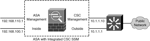
This also means that untrusted hosts on the Internet might be able to communicate with your SSM management interface, too—something that you might not welcome.
You could also connect the SSM management interface to the same management network used by the ASA management interface. This keeps all of the management traffic isolated from other networks. If your management network is totally isolated from the Internet, this setup will not work because the CSC must have a way to contact the Trend Micro servers over the Internet.
Connecting the SSM management interface to a DMZ, as shown in Figure 12-2, offers the most robust solution. Because the SSM management traffic must pass through the firewall to reach external resources such as Trend Micro servers over the Internet, that traffic is protected by the firewall’s stateful inspection. The firewall can also prevent outside hosts from discovering and attempting to exploit the module.
In the example from Figure 12-2, the ASA interfaces are configured with the following commands:
interface Ethernet0/0
nameif outside
security-level 0
ip address 10.1.1.1 255.255.255.0
!
interface Ethernet0/1
nameif inside
security-level 100
ip address 192.168.100.1 255.255.255.0
!
interface Ethernet0/2
nameif dmz
security-level 50
ip address 192.168.110.1 255.255.255.0
Figure 12-2 Connecting the SSM Management Interface to a DMZ
The SSM management interface will eventually be configured with IP address 192.168.110.10. This cannot be done from the ASA configuration because the AIP or CSC maintains its own management interface configuration. However, the ASA does need to be configured to support outbound connections for a CSC module to “call home” to Trend Micro for its updates. This can be done through a dynamic PAT operation, using the following ASA configuration commands:
global (outside) 1 interface
nat (dmz) 1 192.168.110.0 255.255.255.0
Here, the SSM management interface (192.168.110.10) would be translated to the outside interface address (10.1.1.1) during outbound connections. Keep in mind that you need to be able to connect to the SSM management interface to configure and monitor the module. The following ASA configuration commands enable outbound connections from a PC on the inside network toward the SSM on the DMZ network:
global (dmz) 1 interface
nat (inside) 1 192.168.100.0 255.255.255.0
One drawback to the preceding configuration is that you can only manage the SSM from the inside or DMZ networks. This is because dynamic PAT makes the SSM management interface appear as the ASA outside interface from the outside, using a dynamically assigned port number. To manage the module from the outside, the management interface must have a static address translation to an address that is reachable from the outside.
The following ASA configuration commands set up a static NAT so that the SSM appears as outside address 10.1.1.10. As well, an access list is created to permit inbound connections to the SSM management interface. With a CSC, all management connections use TCP port 8443; for an AIP, TCP port 443 would be used instead:
static (dmz,outside) 10.1.1.10 192.168.110.10 netmask 255.255.255.255
!
access-list acl_outside extended permit tcp any host 10.1.1.10 eq 8443
access-group acl_outside in interface outside
At this point, you should also consider whether you will be collecting e-mail or Syslog alerts from the SSM as it performs its functions. The CSC or AIP module itself will be configured in a later step, but the ASA should be configured separately to permit the e-mail or Syslog traffic coming from the SSM management interface address.
As an example, you can use the following ASA configuration commands to permit Syslog messages to the Syslog server located at inside address 192.168.100.15 and e-mail messages to any IP address:
access-list acl_dmz extended permit udp host 192.168.110.10 host 192.168.100.15 eq syslog
access-list acl_dmz extended permit tcp host 192.168.110.10 any eq smtp
access-group acl_dmz in interface dmz
12-2 Configuring the CSC SSM
The Content Security and Control (CSC) SSM was introduced with ASA release 7.1(1). The CSC is used in conjunction with the ASA to provide a variety of inspections and defenses based on traffic content.
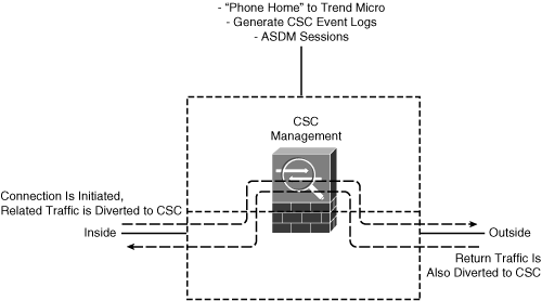
The CSC communicates with the ASA over an internal backplane connection. Figure 12-3 shows how traffic is passed between the ASA and CSC. The ASA diverts traffic classified by a class map to the CSC module over the internal connection. The CSC inspects the traffic in both the forward and return directions so that it can block or modify the contents.
Figure 12-3 Basic CSC SSM Operation
CSC SSM cannot support stateful failover because it does not maintain connection information about the traffic it inspects. Therefore, it cannot provide the failover unit with information necessary for stateful failover.
The connections that a CSC SSM is scanning are dropped upon failure of the security appliance in which the CSC SSM is installed. When the standby ASA becomes active, it forwards the scanned traffic to its own CSC SSM, and any existing connections are reset.
Configuring the ASA to Divert Traffic to the CSC SSM
As you work through initially installing and configuring your CSC SSM, keep in mind that the ASA and CSC SSM are essentially two independent pieces of hardware. Even though the CSC lives in an SSM slot on the ASA chassis, the two communicate over an out-of-band connection only for basic setup and status information. Even though the CSC SSM is installed and the ASA sees it as an active module, the ASA does not send any traffic to the CSC until you configure it to do so.
Any type of traffic traveling in any direction can be diverted to the CSC. For example, you can configure the ASA to send all traffic to the CSC for inspection. However, the CSC can inspect only the following types of traffic:
• Simple Mail Transfer Protocol (SMTP)—TCP port 25
• Post Office Protocol version 3 (POP3)—TCP port 110
• Hypertext Transfer Protocol (HTTP)—TCP port 80
• File Transfer Protocol (FTP)—TCP port 21
If you send any other types of traffic, the CSC is forced to look at those packets, discovers that they are not of the supported types, and ignores them. In other words, the CSC should not have to waste its time and resources looking at traffic it cannot inspect anyway.
Instead, you should identify only the types of traffic that can be inspected in your network setting. For example, if you have SMTP servers inside your network, then you should divert SMTP traffic to the CSC. If you do not have FTP servers, then do not divert FTP traffic to the CSC.
In addition, think about the direction that the inspected traffic is traveling. If you have an SMTP server inside your network, chances are that e-mail is reaching your users as SMTP packets traveling inbound to the server. Therefore, inbound SMTP should be diverted to the CSC so that inbound spam, viruses, and other malware can be detected on the way into your network. Most of the configuration examples shown in the Cisco documentation show only inbound SMTP diverted to a CSC. However, you might also want to divert outbound SMTP to the CSC, to detect and prevent any spam being sourced by your internal users.
Traffic is diverted to the CSC through a service policy that is applied to a firewall interface. As with any service policy, interesting traffic must be grouped into a traffic class, and a specific action must be taken. In this case, the traffic class is defined by an access list. The goal is to have one unique service policy applied to each firewall interface for traffic entering that interface. For example, you might have the following service policies:
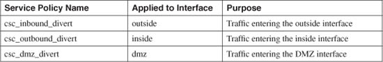
You can use the following steps to configure and apply a service policy on a firewall interface. Repeat these steps for other interfaces:
1. Identify traffic with an access list.
Create an access list with an arbitrary name. You should permit traffic to be diverted to the CSC and deny traffic that does not need to be inspected. For inbound traffic on the outside interface, you can use the following template:
Firewall(config)# access-list acl_name_inbound permit tcp any inside_subnet eq 80
Firewall(config)# access-list acl_name_inbound permit tcp any inside_smtp_address eq 25
For outbound traffic on the inside interface, you can use the following template:
Firewall(config)# access-list acl_name_outbound permit tcp inside_subnet inside_mask
any eq 80
Firewall(config)# access-list acl_name_outbound permit tcp inside_subnet inside_mask
any eq 25
Firewall(config)# access-list acl_name_outbound permit tcp inside_subnet inside_mask
any eq 110
Firewall(config)# access-list acl_name_outbound permit tcp inside_subnet inside_mask
any eq 21
2. Group traffic into a class.
Create a class map with an arbitrary name. This class contains all traffic in one direction only. The class matches against the access list created in Step 1. Use the following configuration commands to create the class map:
Firewall(config)# class-map class_map_name
Firewall(config-cmap)# match access-list acl_name
Firewall(config-cmap)# exit
3. Define a policy to divert traffic to the CSC.
Create a policy map that references the class map created in Step 2. The policy map acts on traffic in one direction only. The traffic is diverted to the CSC with the csc command. Use the following configuration commands to create the policy map:
Firewall(config)# policy-map policy_map_name
Firewall(config-pmap)# class class_map_name
Firewall(config-pmap-c)# csc {fail-close | fail-open}
Firewall(config-pmap-c)# exit
Firewall(config-pmap)# exit
Use the fail-close keyword to make the ASA stop forwarding traffic if the CSC module fails. Otherwise, you can use the fail-open keyword to make sure the ASA keeps forwarding traffic during a CSC failure.
4. Apply the policy to a firewall interface.
Finally, apply the policy map created in Step 3 to a firewall interface using the following configuration command:
Firewall(config)# service-policy policy_map_name interface interface_name
The following commands represent a complete example of the configuration commands needed to divert interesting traffic to the CSC. Inbound traffic arriving on the firewall’s outside interface is matched with class map csc_inbound and handled by policy map csc_inbound_policy. Only inbound SMTP and HTTP traffic are diverted, assuming outside clients are sending mail and browsing web content on inside servers:
Firewall(config)# access-list csc_inbound_divert extended permit tcp 192.168.100.0
255.255.255.0 any eq smtp
Firewall(config)# access-list csc_inbound_divert extended permit tcp 192.168.100.0
255.255.255.0 any eq www
!
Firewall(config)# class-map csc_inbound
Firewall(config-cmap)# match access-list csc_inbound_divert
Firewall(config)# exit
!
Firewall(config)# policy-map csc_inbound_policy
Firewall(config-pmap)# class csc_inbound
Firewall(config-pmap-c)# csc fail-close
Firewall(config-pmap-c)# exit
Firewall(config-pmap)# exit
!
Firewall(config)# service-policy csc_inbound_policy interface outside
For outbound traffic arriving at the firewall’s inside interface, class map csc_outbound matches traffic and policy map csc_outbound_policy handles the traffic. Here, only outbound SMTP, POP3, HTTP, and FTP connections are diverted, assuming inside users are heading toward outside servers.
Firewall(config)# access-list csc_outbound_divert extended permit tcp 192.168.100.0
255.255.255.0 any eq smtp
Firewall(config)# access-list csc_outbound_divert extended permit tcp 192.168.100.0
255.255.255.0 any eq pop3
Firewall(config)# access-list csc_outbound_divert extended permit tcp 192.168.100.0
255.255.255.0 any eq www
Firewall(config)# access-list csc_outbound_divert extended permit tcp 192.168.100.0
255.255.255.0 any eq ftp
!
Firewall(config)# class-map csc_outbound
Firewall(config-cmap)# match access-list csc_outbound_divert
Firewall(config-cmap)# exit
!
Firewall(config)# policy-map csc_outbound_policy
Firewall(config-pmap)# class csc_outbound
Firewall(config-pmap-c)# csc fail-close
Firewall(config-pmap-c)# exit
Firewall(config-pmap)# exit
!
Firewall(config)# service-policy csc_outbound_policy interface inside
Even though the CSC has not been configured at this stage, you should verify that the ASA is actually trying to divert traffic to it. You can do this by monitoring the access list counters, which are updated in real time. In the following example, the shaded output highlights the hit count for each access list entry, indicating the number of times a packet matched the condition:
Firewall# show access-list csc_outbound_divert
access-list csc_outbound_divert; 3 elements
access-list csc_outbound_divert line 1 extended permit tcp 192.168.100.0 255.255.255.0
any eq pop3 (hitcnt=479) 0x6dc20704
access-list csc_outbound_divert line 2 extended permit tcp 192.168.100.0 255.255.255.0
any eq www (hitcnt=1473) 0x94f0d51f
access-list csc_outbound_divert line 3 extended permit tcp 192.168.100.0 255.255.255.0
any eq ftp (hitcnt=16) 0x4f7313ea
Firewall#
Configuring the Initial CSC SSM Settings
The CSC SSM must be configured independently of the ASA. You can use several methods to connect to and configure the CSC. Most often, you use ASDM as your interface to the CSC, although other methods are discussed as they are needed. You should use the following steps to configure a CSC SSM:
1. Verify the CSC SSM status.
After a CSC SSM is installed in an ASA chassis, you should verify that the module is powered up and available. You can do that with the show module ASA command, as shown in the following example. Here, the CSC SSM is listed as ASA module 1 in the “up” state.
Firewall# show module
Mod Card Type Model Serial No.
--- -------------------------------------------- ------------------ -----------
0 ASA 5510 Adaptive Security Appliance ASA5510 JMX1014K070
1 ASA 5500 Series Content Security Services Mo ASA-SSM-CSC-10 JAF10252436
Mod MAC Address Range Hw Version Fw Version Sw Version
--- --------------------------------- ------------ ------------ ---------------
0 0016.c789.c8a4 to 0016.c789.c8a8 1.1 1.0(10)0 7.2(1)
1 0018.7317.8eb3 to 0018.7317.8eb3 1.0 1.0(11)2 CSC SSM 6.1
(Build#1519)
Mod SSM Application Name Status SSM Application Version
--- ------------------------------ ---------------- --------------------------
1 CSC SSM Up 6.1 (Build#1519)
Mod Status Data Plane Status Compatibility
--- ------------------ --------------------- -------------
0 Up Sys Not Applicable
1 Up Up
Firewall#
2. Start the CSC Setup Wizard.
The CSC SSM must be configured with some initial information, such as an IP address, basic network settings, and license keys, before it can begin to operate. You should attempt to configure these settings through ASDM first, before trying any other methods.
Within ASDM, click on the Configuration tab at the top of the screen. Then click on the Trend Micro Content Security button on the left side of the screen. If the CSC SSM has never been configured before, you should see the CSC Setup Wizard window appear, as shown in Figure 12-4.
Figure 12-4 The CSC Setup Wizard Begins the Initial Configuration
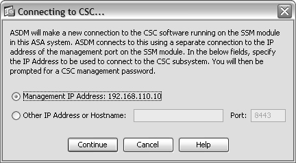
If you see a window titled Connecting to CSC..., as shown in Figure 12-5, instead of the CSC Setup Wizard, the CSC SSM has probably been previously configured. The ASDM fetches the last known management interface IP address from the CSC and offers to use it. If you do not recognize the management IP address, you need to reconfigure the IP address information. Refer to the section “Repairing the Initial CSC Configuration” in this chapter for more information.
Otherwise, the Connecting to CSC... window selects the default IP address that has been configured for the CSC’s management interface. This is fine if your ASDM client can reach the management interface using that address. Suppose the management interface is located on a DMZ interface, but is translated to a different address on the outside of the ASA. In this case, you should select the Other IP Address or Hostname button and enter the translated IP address.
Figure 12-5 A CSC with Preexisting IP Information
After you are connected to the CSC, you can click on the Wizard Setup link to the left of the window and then on the Launch Setup Wizard button to launch the CSC Setup Wizard.
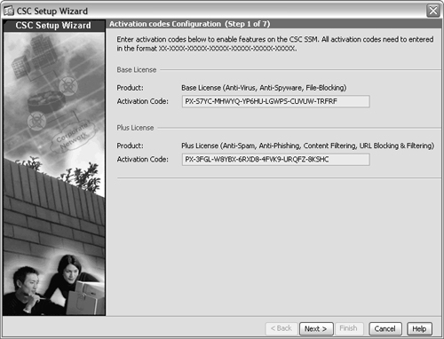
3. Enter the CSC activation codes.
A CSC SSM can have the following two license activation codes:
• Base license—Enables the Anti-Virus, Anti-Spyware, and File Blocking features
• Plus license—Enables the Anti-Spam, Anti-Phishing, Content Filtering, and URL Blocking/Filtering features
If your CSC module does not already have valid activation codes entered, you should enter them in the fields shown in Figure 12-4. You can obtain the activation codes by browsing to http://www.cisco.com/go/license and entering the Product Activation Key (PAK) information that was included with the CSC module.
After the activation codes have been entered into the CSC Setup Wizard, click the Next> button.
4. Enter the IP Configuration.
The CSC Setup Wizard should open an IP Configuration window, as shown in Figure 12-6. Enter the CSC management interface IP address, subnet mask, and default gateway. You should also enter the IP addresses of a primary DNS and an optional secondary DNS. If your environment requires outbound connections to pass through a proxy server, you can also enter the IP address and port number of the proxy server.
5. Enter the CSC Host configuration.
In the window shown in Figure 12-7, you can enter a hostname and domain name that identifies the CSC SSM management interface. The CSC must also know about the e-mail domain used in your network so that it can examine incoming e-mail.
Figure 12-6 Entering the CSC Management IP Configuration
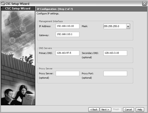
Figure 12-7 Entering the CSC Host Configuration
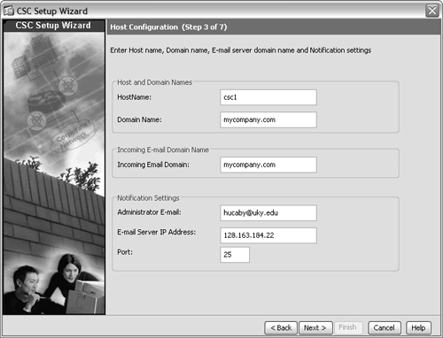
If you want the CSC SSM to send e-mail notifications as it operates, you should enter the e-mail address where those notifications should be sent. The notifications are sent using SMTP, so you should also enter the IP address of your local SMTP server, along with the TCP port used. By default, SMTP uses TCP port 25.
After you have entered the IP configuration information, click the Next> button.
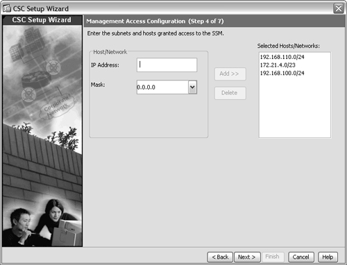
6. Configure management access to the CSC.
You can limit access to the CSC management interface if your security policies require it. In the window shown in Figure 12-8, you can enter an IP address and a subnet mask that identify hosts that are permitted to access the CSC management interface. This can be a single host or an entire subnet. After you enter the address information, you can click the Add>> button to add it to the list of selected entries. By default, a host at any IP address is allowed to reach the CSC, as shown by the 0.0.0.0/0 entry in the list.
Figure 12-8 Limiting Access to the CSC Management Interface
Click the Next> button to continue.
7. Configure the CSC management passwords.
After the initial configuration is completed, you are challenged to enter a password for all future connections to the CSC management interface. By default, the CSC uses password cisco. Because this is commonly known, you should change it now in the window shown in Figure 12-9. However, if you want to leave the password as it is, you can leave the password entries untouched and they will not be changed.
Click the Next> button to continue.
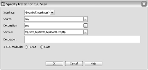
8. Identify traffic to be inspected.
By default, the CSC inspects HTTP, SMTP, POP3, and FTP traffic between any two hosts. You can configure more specific traffic in the window shown in Figure 12-10. Click the Add button to bring up the Specify Traffic for CSC Scan window, where you can enter source and destination addresses, as well as specific protocol and port numbers.
Figure 12-9 Configuring the CSC Management Password
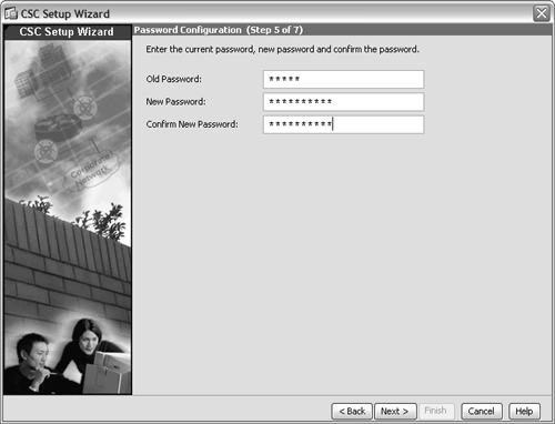
Figure 12-10 Tuning the CSC Traffic Inspection
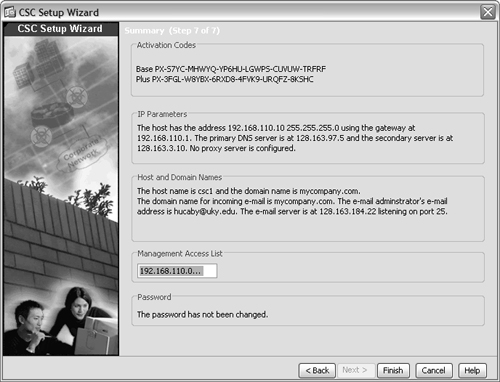
9. Complete the initial configuration.
You should see a window showing a summary of each of the initial CSC configuration settings, as shown in Figure 12-11. At this point, ASDM automatically pushes the settings to the CSC, using an out-of-band connection.
At this point, the CSC management interface has been activated for use. From now on, you are prompted for a password when you try to monitor or configure the CSC.
Repairing the Initial CSC Configuration
If you notice that ASDM is trying to connect to the CSC management interface using an unexpected IP address, you need to repair the initial CSC IP configuration. To do this, first open a CLI-based connection to the ASA, using a console, Telnet, or Secure Shell (SSH) session.
Figure 12-11 ASDM Updates the CSC with the Initial Configuration
Then connect to the CSC SSM through the out-of-band connection it shares with the ASA by using the session command.
In the following example, the CSC is installed as module 1 in the ASA chassis. If you are unsure of the CSC’s module number, use the show module ASA command.
The CSC module prompts for a username and password, rather than a password alone. By default, the username cisco can be used.
Firewall# session 1
Opening command session with slot 1.
Connected to slot 1. Escape character sequence is 'CTRL-^X'.
login: cisco
Password:
Last login: Tue Nov 7 10:51:14 from 127.0.1.1
Trend Micro InterScan for Cisco CSC SSM Setup Main Menu
--------------------------------------------------------------
1. Network Settings
2. Date/Time Settings
3. Product Information
4. Service Status
5. Change Password for Command Line Interface
6. Restore Factory Default Settings
7. Troubleshooting Tools
8. Reset Management Port Access Control List
9. Ping
10. Exit ...
Enter a number from [1-10]:
You should use option 1 to change the initial network settings, as shown in the following example output:
Enter a number from [1-10]: 1
Network Settings
---------------------------------------------------------------------
IP 10.22.213.113
Netmask 255.255.255.192
Hostname csc
Domain name cisco.com
MAC address 00:18:73:17:8E:B3
Primary DNS 10.10.10.10
Secondary DNS 10.10.10.20
Gateway 10.22.213.65
No Proxy
Do you want to modify the network settings? [y | n]
If you continue with the previous scenario, the CSC management interface should have IP address 192.168.110.10—not 10.22.213.113 shown in the current network settings. Therefore, you should choose y to change the settings. In the following example, all of the initial network settings are changed to their appropriate values.
Do you want to modify the network settings? [y | n] y
Network Settings
---------------------------------------------------------------------
Enter the SSM card IP address: (default:10.22.213.113) 192.168.110.10
Enter subnet mask: (default:255.255.255.192) 255.255.255.0
Enter host name: (default:csc) csc
Enter domain name: (default:cisco.com) mycompany.com
Enter primary DNS IP address: (default:10.10.10.10) 128.163.97.5
Enter optional secondary DNS IP address: (default:10.10.10.20) 128.163.3.10
Enter gateway IP address: (default:10.22.213.65) 192.168.110.1
Do you use a proxy server? [y | n] (default:no)
Stopping services: OK
Applying network settings ...
Starting services: OK
Press Enter to continue ...
After the network settings have been corrected, you can go back to ASDM under the Configuration tab and the Trend Micro Content Security button. At that point, ASDM should open a window showing that it plans to connect to the correct CSC management IP address.
Connecting to the CSC Management Interface
After the CSC SSM has received its initial network configuration, you can connect to it through ASDM. When you select the Configuration tab and the Trend Micro Content Security button, ASDM announces that it is getting ready to connect to the CSC, as indicated by the window shown in Figure 12-12.
Figure 12-12 Getting Ready to Connect to the CSC Management Interface

By default, the last known IP address for the CSC management interface is used. In Figure 12-12, this address is 192.168.110.10, which is an address found on the DMZ interface of the ASA. This address can be used if your ASDM host is located on the inside or DMZ interfaces, where the ASA permits connections to that address.
However, if your ASDM host is located elsewhere, such as the outside ASA interface, you need to override the IP address. Select Other IP Address or Hostname and fill in the CSC management interface address as it is known on the outside network. In the example scenario, the ASA is configured to translate DMZ address 192.168.110.10 to outside address 10.1.1.10. Therefore, ASDM should connect to 10.1.1.10 using port 8443.
After ASDM completes the connection to the CSC management interface, it displays a list of configuration options under Configuration > Trend Micro Content Security. As well, you can view a snapshot of CSC activity by clicking the Home button and selecting the Content Security tab.
Configuring Automatic Updates
The CSC SSM must be able to retrieve periodic updates from Trend Micro so that it can stay up to date with current spam, spyware, and virus definitions. You should configure the update parameters next.
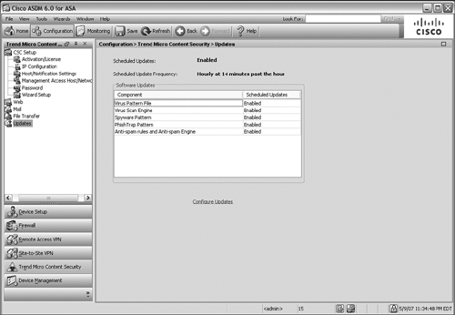
From ASDM, select Configuration and then the Trend Micro Content Security button. Log in to the CSC by entering the password at the prompt. In the list of configuration tasks, click on the Updates entry, which shows a summary of the scheduled updates, as shown in Figure 12-13.
Figure 12-13 Getting Ready to Configure Automatic Updates
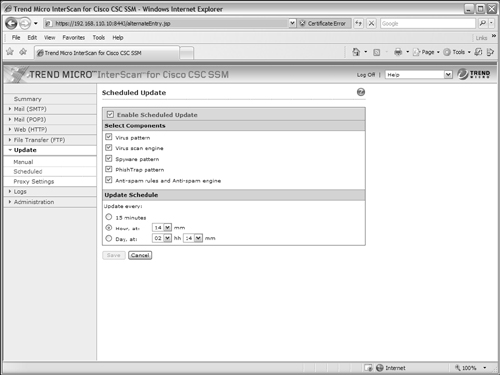
Now click on the Configure Updates link under the list of scheduled updates. This opens a new web session with the CSC management interface, using the Trend Micro InterScan for Cisco CSC SSM user interface. Enter the CSC management password at the prompt and click on the Log On button. You should see a browser page like the one shown in Figure 12-14.
In the left-hand list, make sure Scheduled is selected. In the Scheduled Update portion of the window, make sure the Enable Scheduled Update checkbox is checked. Then check each type of update you want to keep updated from the following list:
• Virus pattern—The database of virus signatures
• Virus scan engine—The virus scan software itself
• Spyware pattern—The database of spyware signatures
• PhishTrap pattern—The database of anti-phishing signatures
• Anti-spam rules and Anti-spam engine—The database of spam detection rules and known spam relays
Select the update schedule you would like to use, under Update Schedule. By default, updates occur every hour at 14 minutes past the hour. You can select intervals of every 15 minutes, every hour (at a specific minute), or every day (at a specific hour and minute). Click on the Save button to save the update configuration.
Figure 12-14 Configuring Scheduled Update Parameters
If your network environment uses a proxy server to control outbound connections, click on the Proxy Settings link and fill in the settings to define the proxy server address, port, and authentication. Click the Save button to save the proxy settings.
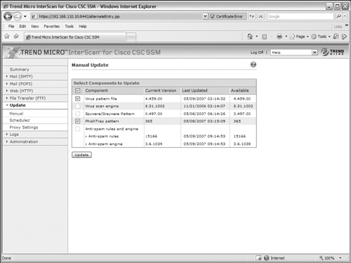
At this point, you should perform a test to verify that the CSC SSM can indeed get an update from the Trend Micro servers. Most likely, it will not be time for a scheduled update, so you have to force a manual update. In the Trend Micro InterScan for Cisco CSC SSM browser window, click on the Manual link under the Update category. The manual update begins as the CSC checks for the availability of new components from Trend Micro.
The manual update shows a list of current CSC components along with their version numbers. If newer versions of any of them are found, those are shown in the list with a checkbox and their version numbers in red, as shown in Figure 12-15.
Select each new component by checking their checkboxes and then click the Update button. The update process begins; while this is happening, you should not try to change any other settings on the CSC. If the update is successful, the components are shown in a list again, along with a timestamp when each was updated. The checkboxes are grayed out so that you cannot select them again.
Figure 12-15 Setting Up a Manual Update
Configuring CSC Inspection Policies
You can configure the CSC SSM to inspect any of the following types of interesting traffic:
• Web—Specific URLs and known phishing sites can be blocked, access to websites can be restricted based on a category, file types can be blocked from downloading, and web page content and webmail content can be scanned for undesirable content.
• Mail—Incoming and outgoing SMTP traffic, as well as inbound POP3 traffic, can be scanned for undesirable content. Both SMTP and POP3 can be scanned for spam content and can be filtered according to text strings contained in the subject or body, and according to attachment size, filename, and file type.
• File Transfer—FTP traffic can be scanned for undesirable content. In addition, files downloaded by FTP can be filtered according to file type.
These categories are shown in ASDM under the Configuration > Trend Micro Content Security screen. When you click on any of the category names, ASDM shows a list of inspection types within that category. However, when you click on an inspection type to configure, ASDM starts up a new browser window using the Trend Micro InterScan for Cisco CSC SSM interface. After the InterScan session begins, you can do all inspection policy configuration from within the same interface without returning to ASDM.
In the Trend Micro InterScan for Cisco CSC SSM session, you can use the links listed on the left side of the screen to navigate to various policy configuration screens. These links are used in the sections that follow.
For HTTP, FTP, or e-mail-based file scanning, the CSC can use its IntelliScan feature to scan files based on a “true file type,” which is determined by header information inside the files, rather than a filename extension. Otherwise, you can specify the filename extensions to be scanned.
Some files might be password-protected or compressed when they are downloaded. The CSC can attempt to scan these files too. You can choose whether to deliver or delete password-protected files. For compressed files, you can set limits on the extent of the file’s compression process, to protect the CSC resources and the amount of time needed to download, uncompress, and deliver the files. Remember that the CSC has to download the complete file and then uncompress it before it can be delivered to the user.
By default, password-protected files are delivered. Compressed files are scanned only if they contain less than 200 internal files, are less than 30 MB, require more than three compression passes, or are more than 100 times the size when uncompressed. If the compressed files are not scanned, they are still delivered by default.
You can configure the CSC to scan files only if they are less than a certain size (50 MB by default). If files are too large to be scanned, they are delivered by default.
Configure Web (HTTP) Inspection Policies
If you plan to have the CSC SSM inspect web traffic for suspicious or unwanted content, you should configure the inspection policies discussed in the following sections.
Configuring URL Blocking
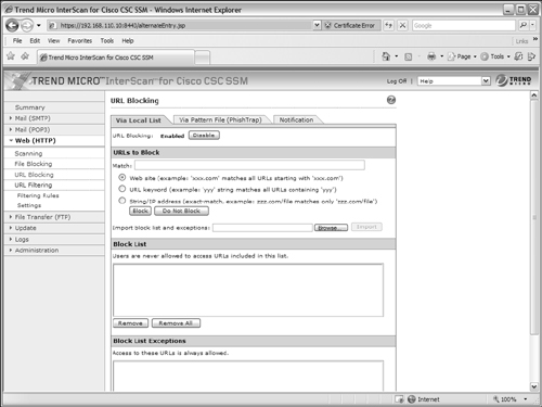
By default, the CSC SSM does not block any URLs that internal users attempt to view. You can configure a local list of strings to match against by selecting the Via Local List tab, as shown in Figure 12-16.
Under Web (HTTP) > URL Blocking, you can enter specific URLs in the Match: field. Click the Block button to add the URL to the block list or the Do Not Block button to permit the URL to be reached. URLs can be matched as specific website address prefixes, keyword matching, or specific hostname/file string matching. Click the Save button to save your changes.
The CSC SSM can also scan URLs to detect phishing sites, spyware sites, virus accomplice sites, and other sites that are known to have malicious purposes. From the Web (HTTP) > URL Blocking page, click on the Via Pattern File (PhishTrap) tab to see the window shown in Figure 12-17. By default, the CSC blocks users from reaching URLs that are known to have any of the listed types of activities. The database of URLs is maintained by Trend Micro and is automatically downloaded to the CSC during the scheduled updates. If you make any changes to the configuration, be sure to click the Save button.
Figure 12-16 Blocking URLs by a Local List
If you discover a website that seems to promote any of the Phish Trap categories is not blocked by the CSC, you can submit the URL to Trend Micro by filling in the URL and category in the bottom portion of the window. Add any notes that describe the website and its behavior to the Note: section and then click on the Submit button. The information you provide is automatically sent to Trend Micro for their analysis.
Finally, you should click on the Notification tab to review the action that the CSC takes when it blocks a user from reaching a URL. By default, the CSC returns the following message in the user’s browser:
The URL you are attempting to access has been blocked. Organization policy does not allow
access to this activity.
You can change that text by editing the User Notification field and clicking the Save button.
Configuring URL Filtering Rules
If your corporate policies warrant, you might want to control what web content your users can browse at different times of the day. The CSC SSM can use its URL Filtering feature to accomplish this automatically. Trend Micro maintains a database of URLs that are broken down into content categories. The CSC downloads this database during scheduled updates and can use it to categorize URLs as they are browsed.
Figure 12-17 Blocking URLs by the Phish Trap Database
First, you must define some policies that the CSC can use to make decisions about whether a URL category is appropriate at any given time. Under the Web (HTTP) > URL Filtering section, go to the Filtering Rules link, as shown in Figure 12-18. Here, you can select whether to block any of the following categories during work time or leisure time (not work time).
• Company prohibited sites
• Not work related
• Research topics
• Business function related
• Customer defined
• Others
Clearly, these categories are rather broad and subjective. You define or tune the categories to meet your own needs as a second step. For now, you can make some broad assumptions based on the general category names. For example, Figure 12-18 shows how Company prohibited sites are blocked during work time and leisure time. That might make sense if your company policies state that users should do only work-related activities while they are at work or are using work-related equipment.
Figure 12-18 Configuring URL Filtering Based on URL Category
Configuring URL Filtering Settings
Next, you can begin to fine tune the URL categories to match your preferences or security policies. Under Web (HTTP) > URL Filtering, select the Settings link. This brings up a new window, as shown in Figure 12-19, with the following configuration tabs:
• URL Categories—Group specific web content sub-categories into the broad URL categories
• URL Filtering Exceptions—Match against URLs that are excluded from filtering
• Schedule—Define specific day and time ranges that are considered as “work time”
• Re-classify URL—Submit a URL to Trend Micro to request it be reclassified in a different category
Use the following steps to configure URL filtering:
1. Define URL categories.
Trend Micro has defined a list of narrow “sub-categories” that describe web content that is available on the Internet. URLs are then mapped to sub-categories based on the content they contain. For example, if a URL presents a page showing people wearing intimate apparel or swimsuits, it might be tagged as belonging to the Intimate Apparel/Swimsuit sub-category.
Figure 12-19 Configuring Settings for URL Filtering
In turn, the CSC can map sub-categories into the broad URL categories that have URL filtering policies applied to them. The list of sub-categories and how they are mapped are shown in Figure 12-19.
By default, sub-categories like Illegal Drugs and Violence/Hate/Racism are mapped into the Company Prohibited Sites category, Gambling is mapped to Non-work Related, and Weapons into the Other category. You can change any of these mappings by selecting the checkboxes of sub-categories you want to move and then choosing a new category from the Move Selected Sub-categories to: drop-down list. Finally, you click on the Move button.
Remember that the sub-categories are mapped into categories, and the categories are enforced during work time and/or leisure time, according to the policies you define.
2. Identify any URL exceptions.
If there are websites that should be exempt from URL filtering and should always be available to your users, you can specify them as filtering exceptions. Select the URL Filtering Exceptions tab under Web (HTTP) > URL Filtering > Settings, as shown in Figure 12-20. You can enter a specific URL as a website, or you can enter a keyword or a text string to match against. Be sure to click the Add button to add your entry to the list of exceptions. Finally, click the Save button to save the changes.
Figure 12-20 Defining URLs That Are Exceptions to URL Filtering
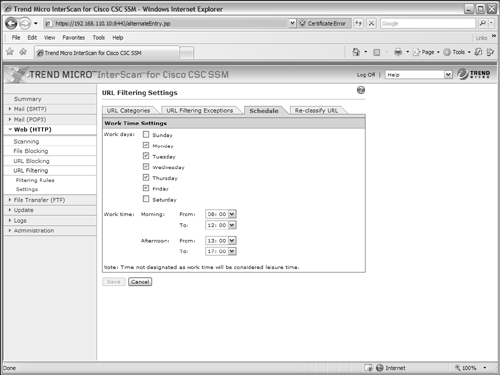
3. Define work time.
The CSC performs URL filtering based on a time schedule. All time is divided into “work time” and “leisure time” (not work time). Therefore, you should configure the CSC to have the correct concept of work time. Select the Schedule tab under Web (HTTP) > URL Filtering > Settings, as shown in Figure 12-21. By default, work time is defined as Monday through Friday, from 08:00 until 12:00, and then from 13:00 until 17:00. To change this, select the checkboxes for any days that contain work time. Then select morning and afternoon start and end times from the drop-down time menus. Be sure to click the Save button when you are finished making changes.
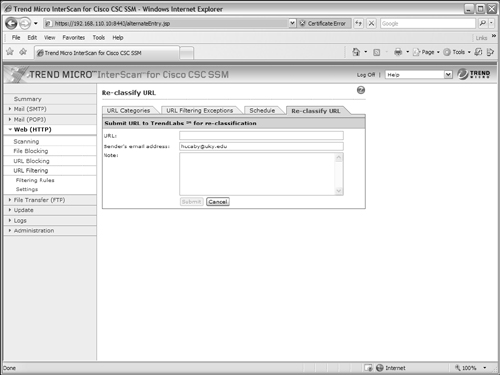
4. Submit a URL for reclassification.
If you find that a URL’s content does not agree with the Trend Micro content category, you can submit the URL to Trend Micro for reclassification. If they agree, they put the URL into the category you suggest. To do this, select the Re-classify URL tab under Web (HTTP) > URL Filtering > Settings, as shown in Figure 12-22. Enter the URL, your e-mail address, and some notes to justify the category where you think the URL should belong. Click the Submit button when you are ready for the CSC to e-mail your request to Trend Micro.
Figure 12-21 Defining the Work Time Schedule
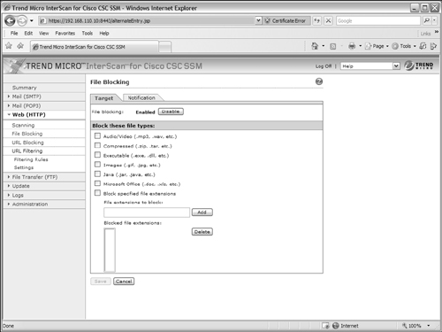
Configuring HTTP File Blocking
As users browse to websites, the CSC can block specific file types from being downloaded. To do this, select the Target tab under Web (HTTP) > File Blocking, as shown in Figure 12-23. Select the files types you want to be blocked from the list of audio/video, compressed, executable, images, Java, and Microsoft Office. You can also specify additional file extensions to be blocked by entering them in the File extensions to block: field and clicking the Add button. After all of your changes have been made, be sure to click the Save button.
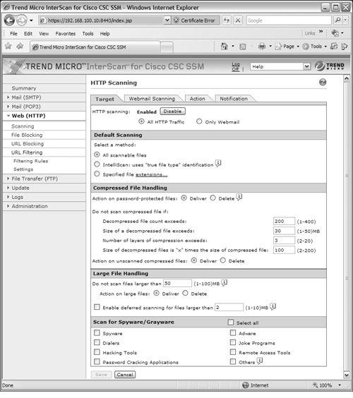
Configuring HTTP Scanning
The CSC can scan files as they are downloaded as part of a web page or HTTP content. HTTP scanning can be done on all HTTP traffic (the default) or on webmail traffic only. To configure HTTP scanning, select the Target tab under the Web (HTTP) > Scanning link, as shown in Figure 12-24.
You can use the following sequence of steps to configure HTTP scanning on a CSC SSM:
1. Configure file scanning.
First, choose the default type of file scanning. By default, the CSC scans all files as they are downloaded as part of a web page content.
Figure 12-22 Requesting That a URL Be Reclassified in a Different Category
You can also specify individual types of spyware and grayware content to be detected during HTTP file scanning. By default, none of these types are detected. Be sure to click the Save button when you are finished configuring the Target tab.
2. Configure webmail scanning.
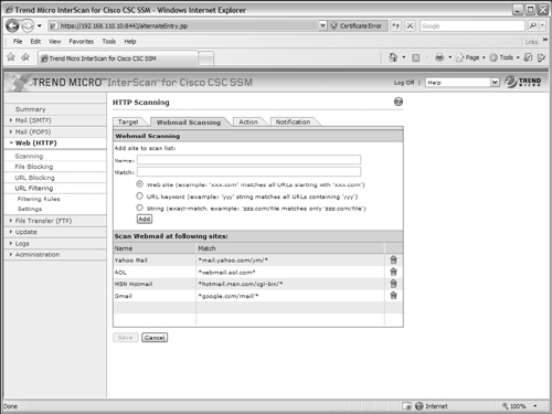
To configure the CSC to scan webmail content, select the Webmail Scanning tab under the Web (HTTP) > Scanning link, as shown in Figure 12-25.
By default, the CSC scans webmail content when users go to the Yahoo! Mail, AOL, MSN Hotmail, or Gmail sites using the URL patterns shown in Figure 12-25. You can add other specific URLs or keywords and text strings to match if your users go to webmail sites other than those listed. Enter a descriptive name in the Name field and a URL or match string in the Match field. Click the Add button to add the entries to the webmail scan list. Be sure to click the Save button after you are finished with the configuration.
Figure 12-23 Specifying File Types to Block in HTTP Content
3. Specify an action.
By default, the CSC attempts to clean files that it finds infected with a virus or malware. If a file cannot be cleaned, it is deleted from the HTTP content. Any spyware or grayware is deleted rather than delivered. You can change these policies by selecting the Action tab under the Web (HTTP) > Scanning link.
4. Define the notification.
When the CSC detects an infected file that it also deletes, it posts the following message to the user’s browser:
The InterScan for CSC SSM has scanned the file you are attempting to transfer, and
has detected a security risk - the file will not be transferred.
You can change that message by editing the text under the Notification tab.
Configuring File Transfer (FTP) Inspection Policies
If you plan to have the CSC SSM inspect FTP traffic for suspicious or unwanted content, you should configure the inspection policies discussed in the following steps.
Figure 12-24 Configuring HTTP File Scanning
1. Configure inspection policies for file scanning.
The CSC can scan files to detect undesirable content as the files are downloaded by FTP. This process and its configuration are very similar to HTTP scanning. To configure FTP file scanning, select the Target tab under the File Transfer (FTP) > Scanning link, as shown in Figure 12-26.
First, choose the default type of file scanning. By default, the CSC scans all files as they are downloaded through an FTP connection.
You can also specify individual types of spyware and grayware content that is detected during FTP file scanning. By default, none of these types are detected. Be sure to click the Save button when you are finished configuring the Target tab.
By default, the CSC attempts to clean files that it finds infected with a virus or malware. If a file cannot be cleaned, it is deleted and not delivered to the end user. Any spyware or grayware is deleted rather than delivered. You can change these policies by selecting the Action tab under the File Transfer (FTP) > Scanning link.
Figure 12-25 Configuring Webmail Scanning
When the CSC detects an infected file that it also deletes, it posts the following message to the user’s browser:
The InterScan for CSC SSM has scanned the file you are attempting to transfer, and
has detected a security risk - the file will not be transferred.
You can change that message by editing the text under the Notification tab.
2. Configure inspection policies for FTP file blocking.
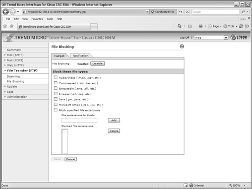
As users attempt to download files by FTP, the CSC can block specific file types from being downloaded. To do this, select the Target tab under File Transfer (FTP) > File Blocking, as shown in Figure 12-27.
Select the files types you want to be blocked from the list of audio/video, compressed, executable, images, Java, and Microsoft Office. You can also specify additional file extensions to be blocked by entering them in the File extensions to block: field and clicking the Add button. After all of your changes have been made, be sure to click the Save button.
Configuring Mail (SMTP and POP3) Inspection Policies
If you plan to have the CSC SSM inspect e-mail traffic for suspicious or unwanted content, you should configure the inspection policies discussed in the sections that follow. The CSC can scan inbound traffic destined for SMTP servers, outbound traffic destined for SMTP servers, and inbound POP3 traffic destined for clients.
Figure 12-26 Configuring FTP File Scanning
Also, the CSC can filter the content of e-mail messages, based on the file type and content of attachments. You can also configure the CSC to scan for spam e-mail and take action on offending messages.
Scanning SMTP Traffic
The CSC can scan SMTP messages to detect undesirable or malicious content. You can configure SMTP scanning by going to Mail (SMTP) > Scanning and then selecting either the Incoming or Outgoing link, depending on the direction that SMTP traffic is traveling in your network. If you have an SMTP server on the inside or DMZ interface of the ASA, configure incoming scanning to watch traffic coming in from external clients. Configure outgoing scanning to watch traffic being sent by internal clients:
1. Configure the scanning target.
Figure 12-27 Specifying File Types to Block in FTP Content
Select the Target tab, as shown in Figure 12-28. First, choose the default type of file scanning. By default, the CSC scans all attachment files as they are sent through an SMTP connection.
You can also specify individual types of spyware and grayware content to be detected during FTP file scanning. By default, none of these types are detected. Be sure to click the Save button when you are finished configuring the Target tab.
2. Configure the action.
Select the Action tab. If an attachment is found to have a virus or malware, it can be cleaned (the default). As an alternative, the CSC can deliver the message after the offending attachment has been deleted, or it can deliver the original message intact—offending attachment and all.
With spyware and grayware, you can configure the CSC to deliver the offending files or delete them (the default).
3. Configure the notification.
Figure 12-28 Configuring SMTP Message Scanning
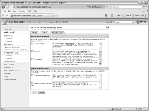
When the CSC detects suspicious content in an e-mail attachment file, it can send a notification. To configure this feature, select the Notification tab as shown in Figure 12-29. By default, no notifications are sent by e-mail. However, you can choose whether to send e-mail notices to the CSC administrator (the e-mail address you configured for CSC notifications), the e-mail message sender, and the e-mail message recipient.
By default, the CSC notifies the e-mail message recipient by inserting a descriptive message into the e-mail message text. You can also configure the CSC to insert a “risk free” message into the text of every message that has clean scanning results.
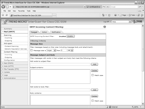
Filtering SMTP Content
You can configure the CSC to filter incoming or outgoing SMTP messages according to specific things that are found in the message itself. Under Mail (SMTP) > Content Filtering, choose the Incoming or Outgoing link (as shown in Figure 12-30), depending on the direction the target e-mail will be traveling in relation to the ASA.
Figure 12-29 Configuring SMTP Message Scanning Notification
You can configure the CSC to filter out messages that are larger or smaller than a given size. This can be handy to filter out messages that contain very large attachments. The CSC can also filter messages if it finds specific words in the subject line or the message body text. To accomplish this, enter the words in the Add words to subject filter field or Add words to body filter field and click on the Add button.
You can also configure the CSC to filter messages according to the attributes of attachments. For example, you can enter specific words or character strings to match against the attachment filenames. You can also select attachment file types to filter out.
Under the Action tab, you can choose whether to delete or deliver (the default) messages that are filtered. You can also select a text message to insert in the mail message to alert the user of the filtered condition. Finally, the Notification tab allows an alert to be sent to the CSC administrator, the message sender, or the message recipient when a message has been filtered.
Detecting Spam SMTP E-mail
The CSC can detect spam e-mail by comparing information found in the message headers with a database maintained by Trend Micro. Anti-spam operation is independent of traffic direction—the CSC simply examines all e-mail messages as they pass through it.
Figure 12-30 Configuring SMTP Message Content Filtering
You can configure the following types of anti-spam detection:
• Content scanning—E-mail messages are examined as they are sent and are compared to a database of known spam patterns maintained by Trend Micro.
• Network reputation services—E-mail senders are examined and compared to a database of IP addresses known to produce spam. The sender’s reputation of being a source of spam is used as the metric for spam detection. This makes identifying spam relays and known spam sources relatively easy and fast.
You can use the following steps to configure SMTP anti-spam operation.
1. Configure SMTP content scanning.
Under the Mail (SMTP) > Anti-spam > Content Scanning link, select the Target tab, as shown in Figure 12-31. You can set the level of anti-spam detection in the Filter Threshold section. By default, the CSC uses a Low setting. The higher the setting, the more likely spam messages are detected. Also, you have a greater chance that the CSC triggers on false positives, or legitimate e-mail messages that it mistakenly labels as spam. If you find that a reasonable number of spam messages are getting through without detection, you can increase the filter threshold.
Figure 12-31 Configuring SMTP Anti-Spam Content Scanning
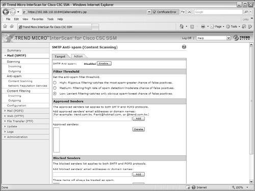
You can also add specific e-mail addresses or domain names to a list of approved senders or blocked senders. If the sender’s address is found in the list of approved senders, the message is delivered without anti-spam detection. If the address is found in the list of blocked senders, all messages from that sender are dropped without delivery.
Under the Action tab, you can configure the action the CSC takes if it detects a spam message. By default, the message is “stamped” by having the text string Spam: added to the subject line. Stamping messages makes it easier for end users to create e-mail filters that can recognize the stamp string and take action automatically. Otherwise, you can configure the CSC to automatically delete spam messages before delivering them.
2. Configure Network Reputation Services.
By default, SMTP anti-spam Network Reputation Services are enabled. The CSC can make use of the following two types of anti-spam services from Trend Micro:
• Real-Time Blackhole List (RBL+)—Spam senders are identified by IP address from a list of known spam originators. This database is accurate and stable, but is not updated at the CSC in real time.
• Quick IP List (QIL)—Spam senders are identified using a dynamic exchange between the CSC and Trend Micro. New spam originators can be identified in real time because the CSC is constantly comparing sender addresses with the QIL content from Trend Micro. This database offers the most timely detection of new spam senders, but requires interactive communication with the Trend Micro servers.
You can set the level of anti-spam detection by going to the Mail (SMTP) > Anti-spam > Network Reputation Services link and selecting the Target tab, as shown in Figure 12-32. Under the Set Service Level section, you can choose High or Low. A setting of High uses the complete Trend Micro Network Anti-spam Service, which can identify known or likely spam senders by IP address, previous spam reputation, or current suspicious activity. A setting of Low uses a more basic Trend Micro database of known spam senders.
Figure 12-32 Configuring SMTP Anti-Spam Network Reputation Services
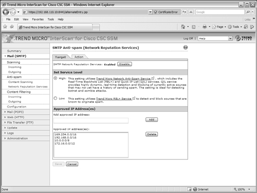
In the Approved IP Address(es) section, the CSC also keeps a list of addresses and subnets that it considers to be trusted or approved senders. Users sending SMTP messages from these addresses are approved to do so. By default, the following addresses are added to the approved list:
• 169.254.0.0/16
• 192.168.0.0/16
• 172.16.0.0/12
Notice that each of these subnets represents private address space as defined in RFC 1918. These addresses are not routable over the Internet and should be found only on an inside or protected interface of the ASA. In other words, the CSC considers your own internal users to have a good reputation in sending spam-free e-mail.
Under the Action tab, you can configure the action to take when e-mail senders are matched as spam senders. The actions are grouped according to the type of anti-spam detection: RBL+ or QIL match. By default, each type of match leads to Intelligent action, where the CSC denies the spam sender’s SMTP connection and sends an SMTP error code. You can also choose to close the SMTP connection with no error code or to simply log the detection and deliver the spam message.
Configuring General SMTP Mail Handling
You can configure some basic policies that affect how the CSC handles SMTP content. Under the Mail (SMTP) > Configuration link, you can select tabs that correspond to the following configuration steps.
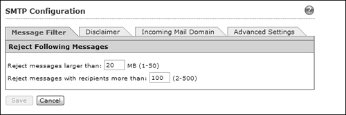
1. Configure the Message Filter tab.
The CSC can flatly reject e-mail messages sent over SMTP if the messages are greater than a maximum size (default 20 MB) or if the messages contain more than a maximum number of recipients (default 100). You can adjust these values as shown in Figure 12-33.
Figure 12-33 Configuring the SMTP Message Filter
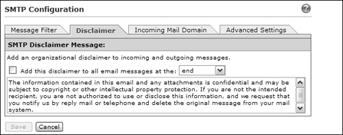
2. Configure the Disclaimer tab.
By default, if the CSC does not detect any suspicious content and decides to deliver STMP e-mail messages, it does not make any changes to the message body. However, if your organization requires users to add a disclaimer to every message, you can configure the CSC to do this for all users automatically.
In fact, you can use the disclaimer message to add any type of text to e-mail messages. For example, your organization might require certain warnings or cautions to be added to educate the mail recipients about specific company policies or legal actions that might be taken.
Using the parameters shown in Figure 12-34, select the Add this disclaimer to all email messages checkbox. Next, choose whether the CSC should add the disclaimer at the beginning or end of e-mail messages from the drop-down list. The CSC uses a default disclaimer text, but you can edit the text field if needed. Click the Save button to save your changes.
Figure 12-34 Configuring the SMTP Disclaimer Message Parameters
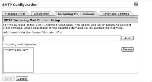
3. Configure the Incoming Mail Domain tab.
The CSC must be able to determine whether SMTP mail is incoming or outgoing when it applies various content detection and blocking functions. If you have SMTP servers inside your organization, then SMTP traffic will be incoming from the Internet toward those servers. The CSC looks at the domain names of e-mail recipients in incoming messages as it examines the e-mail content.
You should add any domain names that are used inside your organization for email purposes. For example, if your users have e-mail addresses of the form [email protected], then enter mycompany.com as an incoming mail domain, as shown in Figure 12-35.
Figure 12-35 Configuring the SMTP Incoming Mail Domain Settings
4. Configure the Advanced Settings tab.
Malicious users can attempt to exploit SMTP connections as they set up an attack. The CSC can monitor the state of SMTP connections and take certain actions to mitigate an attack. You can configure the CSC to automatically time out idle SMTP connections after a time period (default 90 seconds) by adjusting the parameters shown in Figure 12-36.
Figure 12-36 Configuring SMTP Advanced Settings
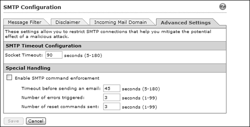
You can also configure the CSC to close SMTP connections if any of the following conditions occur:
• Time elapses before a message is actually sent (default 45 seconds)
• A number of SMTP errors occur (default 3 errors)
• A number of SMTP reset commands are sent (default 3)
Scanning POP3 Traffic
The CSC can scan POP3 mail messages much like it scans SMTP mail. The main difference is that POP3 is used only when clients retrieve mail; SMTP is used when clients send mail. You can configure POP3 scanning by going to the Mail (POP3) > Scanning link and using the following steps:
1. Configure the scanning target
Select the Target tab, as shown in Figure 12-37. First, set the maximum message size that the CSC allows. By default, messages larger than 20 MB are rejected. Next, choose the default type of file scanning. By default, the CSC scans all attachment files as they are sent through a POP3 connection. The CSC can also use its IntelliScan feature to scan files based on a “true file type,” which is determined by header information inside the files, rather than a filename extension. Otherwise, you can specify the filename extensions to be scanned.
Some attachments might be password-protected or compressed when they are downloaded. The CSC can attempt to scan these files, too. You can choose whether to deliver or delete password protected files. For compressed files, you can set limits on the extent of the file’s compression process to protect the CSC resources and the amount of time needed to download, uncompress, and deliver the files. Remember that the CSC has to download the complete file and then uncompress it before it can be delivered to the user.
By default, password-protected files are delivered. Compressed files are scanned only if they contain less than 200 internal files, are less than 20 MB, require more than 3 compression passes, or are more than 100 times the size when uncompressed. If the compressed files are not scanned, they are still delivered by default.
Figure 12-37 Configuring POP3 Message Scanning
You can also specify individual types of spyware and grayware content to be detected during FTP file scanning. By default, none of these types are detected. Be sure to click the Save button when you are finished configuring the Target tab.
2. Configure the action.
Select the Action tab. If an attachment is found to have a virus or malware, it can be cleaned (the default). As an alternative, the CSC can deliver the message after the offending attachment has been deleted, or it can deliver the original message intact—offending attachment and all.
With spyware and grayware, you can configure the CSC to deliver the offending files or delete them (the default).
3. Configure the notification.
When the CSC detects suspicious content in an e-mail attachment file, it can send a notification. To configure this feature, select the Notification tab. By default, no notifications are sent by e-mail. However, you can choose whether to send e-mail notices to the CSC administrator (the e-mail address you configured for CSC notifications), the e-mail message sender, and the e-mail message recipient.
By default, the CSC notifies the e-mail message recipient by inserting a descriptive message into the e-mail message text. You can also configure the CSC to insert a “risk free” message into the text of every message that has clean scanning results.
Detecting Spam in POP3 E-mail
The CSC can detect spam messages as they are retrieved through POP3 mail connections. Detecting spam in POP3 is a bit simpler than SMTP because e-mail messages are coming from a server toward the clients. With POP3, messages are always retrieved, so none of the parties involved can be a spam source; if spam exists, it is only as messages already queued for clients.
Under the Mail (POP3) > Anti-spam link, select the Target tab as shown in Figure 12-38. You can set the level of anti-spam detection in the Filter Threshold section. The higher the setting, the more likely spam messages are detected. However, the higher the setting also means a greater chance exists that the CSC triggers on false positives, or legitimate e-mail messages that it mistakenly labels as spam. If you find that a reasonable number of spam messages are getting through without detection, you can increase the filter threshold. Remember that POP3 anti-spam detection examines e-mail messages as they are received.
Figure 12-38 Configuring POP3 Anti-Spam Content Scanning
You can also add specific e-mail addresses or domain names to a list of approved senders or blocked senders. If the sender’s address is found in the list of approved senders, the message is delivered without anti-spam detection. If the address is found in the list of blocked senders, all messages from that sender are dropped without delivery.
Under the Action tab, you can configure the action the CSC takes if it detects a spam message. By default, the message is “stamped” by having the text string Spam: added to the subject line. Stamping messages makes it easier for end users to create e-mail filters that can recognize the stamp string and take action automatically. Otherwise, you can configure the CSC to automatically delete spam messages before delivering them.
Filtering POP3 Content
You can configure the CSC to filter POP3 messages according to specific things that are found in the message itself. Click on the Mail (POP3) > Content Filtering link, as shown in Figure 12-39.
Figure 12-39 Configuring POP3 Message Content Filtering
You can configure the CSC to filter out messages that are larger or smaller than a given size. This can be handy to filter out messages that contain very large attachments. The CSC can also filter messages if it finds specific words in the subject line or the message body text. To accomplish this, enter the words in the Add words to subject filter field or Add words to body filter field and click on the Add button.
You can also configure the CSC to filter messages according to the attributes of attachments. For example, you can enter specific words or character strings to match against the attachment filenames. You can also select attachment file types to filter out.
Under the Action tab, you can choose whether to delete or deliver (the default) messages that are filtered. You can also select a text message to insert in the mail message to alert the user of the filtered condition. Finally, the Notification tab allows an alert to be sent to the CSC administrator when a message has been filtered.
12-3 Configuring the AIP SSM
The Advanced Inspection and Prevention (AIP) SSM was introduced with ASA release 7.0(1). The AIP is used as a single Intrusion Protection System (IPS) in conjunction with the ASA to provide robust intrusion inspection functions based on a set of signatures.
Beginning with ASA release 8.0(1), and Cisco IPS 6.0 running on the AIP, you can configure more than one virtual sensor. The ASA can take advantage of the virtual sensors to inspect traffic on different interfaces, in different security contexts, and according to different policies. The ASA and AIP module can also perform anomaly detection to discover Internet worms that are scanning for targets to attack.
Tip
For complete information about Cisco IPS sensors and their operation, you can refer to Intrusion Prevention Fundamentals by Earl Carter and Jonathan Hogue, Cisco Press, ISBN 1-58705-239-3.
Initially Configuring the AIP
After an AIP SSM has been installed in an ASA chassis, you need to connect to it and provide an initial configuration. This must be done through the AIP’s management interface, according to the following steps:
1. Connect to the AIP from the ASA CLI.
First, locate the AIP SSM within the chassis with the show module command. Then open a terminal session to the AIP’s out-of-band channel with the session slot_number command, as in the following example:
Firewall# show module
Mod Card Type Model Serial No.
--- -------------------------------------------- ------------------ -----------
0 ASA 5510 Adaptive Security Appliance ASA5510 JMX1014K070
1 ASA 5500 Series Security Services Module-10 ASA-SSM-10 JAB101300TZ
Mod MAC Address Range Hw Version Fw Version Sw Version
--- --------------------------------- ------------ ------------ ---------------
0 0016.c789.c8a4 to 0016.c789.c8a8 1.1 1.0(10)0 8.0(1)18
1 0015.c695.d461 to 0015.c695.d461 1.0 1.0(10)0 6.0(2)
Mod SSM Application Name Status SSM Application Version
--- ------------------------------ ---------------- --------------------------
1 IPS Up 6.0(2)
Mod Status Data Plane Status Compatibility
--- ------------------ --------------------- -------------
0 Up Sys Not Applicable
1 Up Up
Firewall#
Firewall# session 1
Opening command session with slot 1.
Connected to slot 1. Escape character sequence is 'CTRL-^X'.
login: cisco
Password:
By default, the AIP is configured with username cisco and password cisco. Because these defaults are well known, you should change them as soon as possible, as part of the initial setup in Step 2.
2. Run the initial setup.
As soon as you log in to the AIP through a terminal session the first time, the AIP prompts for the current username and password (both cisco by default), as well as a new password.
At this point, you are at a command prompt where you can enter the setup command. The AIP displays its current settings and then prompts you through a dialog to change the configuration.
As the AIP prompts for each network parameter, you can press the Enter key to accept the default value, or you can enter a new value. The setup process begins with a prompt to continue; press the Enter key to begin, as in the following example:
Current time: Mon May 14 08:39:16 2007
Setup Configuration last modified: Tue May 08 22:21:25 2007
Continue with configuration dialog?[yes]:
a. Set the AIP hostname and prompt.
In the following example, the AIP is configured to have its prompt changed from the default sensor to aip:
Enter host name[sensor]: aip
b. Set the management interface address.
The IP address, subnet mask (as a CIDR bit mask or the number of network bits), and default gateway are all configured on a single line, in the following format:
ip_address/bits,gateway_address
Be sure to separate the IP address and mask with a forward slash and the mask and gateway address with a comma. In the following example, the AIP management interface is assigned IP address 192.168.100.11, subnet mask 255.255.255.0 (/24), and default gateway 192.168.100.1:
Enter IP interface[10.1.9.201/24,10.1.9.1]: 192.168.100.11/24,192.168.100.1
c. Configure the Telnet server.
The AIP can accept Telnet connections on its management port, if they are needed. By default, Telnet is disabled. Because Telnet is not a secure protocol, you should keep it disabled by pressing the Enter key to accept the default:
Enter telnet-server status[disabled]:
d. Set the web server port number.
By default, the AIP allows SSL connections to its management interface over TCP port 443. You can accept the default port number by pressing Enter, or you can enter a new port number at the following prompt:
Enter web-server port[443]:
e. Identify addresses that can manage the AIP.
The AIP maintains an internal access list to limit which client IP addresses are allowed to connect to the management port. By default, all IP addresses are denied access. You should enter the IP subnets or addresses where trusted administrative users are located, so the AIP allows them to connect. Enter each IP address with a CIDR mask, as in the following example:
Modify current access list?[no]: yes
Current access list entries:
Delete:
Permit: 10.0.0.0/8
Permit: 192.168.1.0/24
You can keep adding one IP address/mask at each Permit prompt. Single IP addresses can be added with a /32 mask (255.255.255.255). When you are finished adding addresses, press the Enter key by itself.
f. Configure the AIP clock.
By default, the AIP uses the ASA chassis as its time source. The AIP can also synchronize its time with an external NTP server, independent of the ASA chassis. The simplest solution is to configure the ASA chassis to use an NTP server and then the AIP can synchronize with the ASA.
Regardless, the AIP synchronizes only the date and current time (hours, minutes, seconds) with the ASA or NTP server. The time zone and summer time settings are all maintained independently on the AIP. If you want to use a time zone that is different from the default UTC, you have to configure the AIP accordingly. In the following example, the AIP is configured to use the ASA chassis (not NTP) with a recurring summer time or DST beginning on the second Sunday of March at 02:00:00 and ending on the first Sunday of November at 02:00:00:
Modify system clock settings?[no]: yes
Use NTP?[no]:
Modify summer time settings?[no]: yes
Recurring, Date or Disable?[Recurring]:
Start Month[april]: march
Start Week[first]: second
Start Day[sunday]: sunday
Start Time[02:00:00]: 02:00:00
End Month[october]: november
End Week[last]: first
End Day[sunday]: sunday
End Time[02:00:00]: 02:00:00
DST Zone[]: EDT
Offset[60]:
Modify system timezone?[no]: yes
Timezone[UTC]: EST
UTC Offset[0]: -5
Also, the AIP’s time zone is called “EST” and is 5 hours behind UTC.
g. Identify sensor interfaces.
By default, no AIP interfaces are configured to accept traffic for inspection. You can assign interfaces to virtual sensors as a part of the initial configuration. However, you should take full advantage of the user interface in ASDM or IPS Device Manager (IDM) instead. In that case, choose the default no answer when you are prompted for interface/virtual sensor configuration.
Modify interface/virtual sensor configuration?[no]:
h. Configure default threat protection settings.
By default, the AIP is configured to provide threat detection on its virtual sensor vs0. Only high risk (risk ratings 90 through 100) are prevented. You can configure these settings in the initial setup here, if needed:
Modify default threat prevention settings?[no]:
However, you should consider doing this through the IDM interface instead. After the initial setup is done, IDM provides a much more robust management platform.
3. Reset the AIP.
Before the initial settings can be used, the AIP must be reset or rebooted. You can do this from the AIP session with the reset command.
Managing the AIP
You can manage the AIP from a GUI interface in two ways:
• Open a web browser to the AIP’s management interface address as https://aip-ip-address
• Access the AIP through ASDM
Actually, both methods provide the same configuration and management tools in slightly different formats. The AIP web front end is called IPS Device Manager (IDM) and provides a native interface into the module’s configuration. If you use ASDM, all of the same AIP functions are presented within the ASDM structure, providing a single management platform for all ASA-related features.
To access the AIP from within ASDM, select the Configuration tab and the IPS link in the left-hand column, as shown in Figure 12-40.
Figure 12-40 Configuring an AIP from Within ASDM
Tip
The AIP uses a self-signed certificate, so your web browser will likely complain about its validity. The simplest workaround is to click on the Continue to this website (not recommended) link in your browser.
Updating the AIP License
The AIP cannot inspect traffic at all until it has a valid license. In addition, you will not be able to access new IPS signature databases or upload them to the AIP without an active license and Cisco support contract.
If you purchased a license and support contract, you can enter the license key in one of two ways:
• Directly from Cisco Connection Online (CCO, Cisco.com) or from ASDM/IDM
• Upload from the ASDM or IDM client
In ASDM, select the Configuration tab and then click on the IPS button in the left-hand column. You should see a window similar to that displayed in Figure 12-41.
Figure 12-41 Updating the AIP License
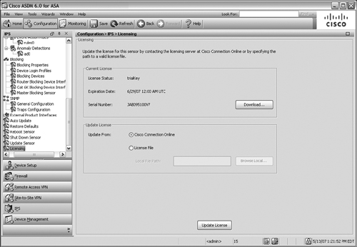
If you select the Update from Cisco Connection Online option, the AIP opens a connection to Cisco.com directly. It attempts to request and download a license automatically. If it is not successful, it gives you the option to request a 30-day trial license key.
If you received a license from Cisco in an e-mail, you can save the license as a file and upload it to the AIP. Select the Update from License File option and then click on the Browse Local button to locate the file. Finally, click on the Update License button to upload and install the license file.
Manually Updating the AIP Code or Signature Files
Occasionally, you might need to update the IPS code image or the signature database file on the AIP module. You can do this manually through the ASDM or IDM interface.
First, download the new file from Cisco.com and save it on a local server. The AIP can retrieve an image file from an FTP, HTTP, HTTPS, or Secure Copy (SCP) server. You can also download the file and save it locally on the ASDM client machine.
From ASDM, select the Configuration tab and then IPS in the left-hand column. In the IPS task list, select Update Sensor, as shown in Figure 12-42.
Figure 12-42 Updating an AIP Image or Signature File
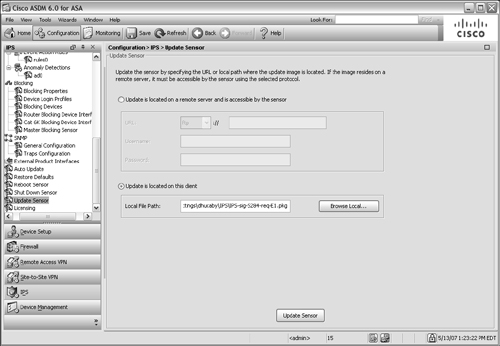
You can select Update is located on a remote server and is accessible by the sensor and supply the server type and URL, as well as a username and password. If you stored the image file on the local ASDM client machine, select Update is located on this client and click on the Browse Local button to locate the file.
Finally, click on the Update Sensor button to download the file to the AIP. If you updated the AIP image file, you also have to reboot the AIP to begin using the new code image. Signature database files, on the other hand, can be uploaded and used immediately without rebooting.
Automatically Updating AIP Image and Signature Files
Manually updating files on one AIP can be somewhat tedious, but updating files on many AIP modules can get out of hand. You can make use of the Auto Update feature to configure one or more AIPs to leverage a more automatic process. An AIP can poll an FTP or SCP server at regular intervals to see if new files are available. If so, the AIP downloads the new files and begins using them.
In ASDM, select the Configure tab and then IPS, followed by the Auto Update link in the scrolling list. You should see a window like that in Figure 12-43.
Figure 12-43 Using Auto Update to Keep AIP Files Up to Date
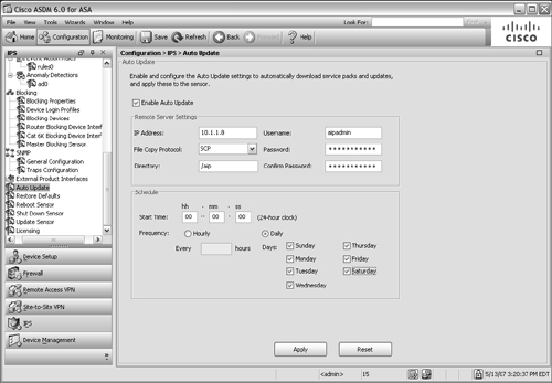
First, configure the AIP to begin polling the Auto Update Server (AUS) for new files. Click on the Enable Auto Update checkbox and then enter the IP address of the AUS machine, along with a valid username and password. Select the protocol to use for file copying (SCP or FTP) and the directory where the AIP files can be found.
Finally, enter the polling schedule that the AIP should use. Cisco can sometimes publish new IPS signature database files at least once a day, so you should consider selecting each day of the week for Auto Update. After you have entered all of the fields, click on the Apply button.
Tip
If you have a currently active IPS maintenance contract with Cisco, you can access the most up-to-date IPS image and signature database files.
http://www.cisco.com/kobayashi/sw-center/ciscosecure/ids/crypto/index.shtml—Click on Latest Signature Update link.
You can subscribe to the Cisco IPS Active Update Bulletin by going to http://www.cisco.com/offer/newsletter/123668_4 and filling in your information. The bulletins are sent each time a new IPS signature update is released.
The Cisco Security IntelliShield Alert Manager service provides customized alerts of new vulnerabilities and threats. See http://www.cisco.com/go/intellishield for more information.
IPS Policies
An IPS sensor like the AIP performs all of its inspections and analysis based on a set of policies. The policies are built on three components:
• IPS signatures—A database of predefined signatures or ways to describe suspicious activity; signatures are based on characteristics of the data being passed.
• Event actions—The IPS sensor takes predefined actions on each signature that is detected in a traffic flow.
• Anomaly detection—The IPS sensor can detect traffic anomalies or suspicious activity related to Internet worm propagation.
By default, an AIP is preconfigured with a signature definition called sig0, a set of event action rules called rules0, and a set of anomaly detections called ad0. You can use the default policies or you can create your own through ASDM or IDM.
Working with Signature Definitions
From the ASDM, you can view the default signature definition sig0 by selecting the Configuration tab, then the IPS function, and then the Signature Definitions link under Policies in the scrolling list. Figure 12-44 shows a sample of sig0. Each signature has the following attributes:
• A unique signature ID—Each signature has a predefined identifier, shown in the Sig ID column
• A descriptive name—A text string that describes the purpose of the signature
• A severity factor—The severity factor is based on the following levels: Informational (25), Low (50), Medium (75), or High (100)
• A fidelity rating—A weighting (1–100) of how well the signature might perform without any prior knowledge of the traffic target
• A base RR—The base risk rating (1–100) or a composite index based on the severity level times the fidelity rating
• An action—The action taken by the AIP when the signature fires
You can use the default signature definition sig0 as-is, or you can make changes to individual signatures within sig0. Also, you can create your own customized signature definition based on sig0. To create a new definition, select Signature Definitions in the scrolling list and then select sig0 under Policy Name. You can click on the Clone button to make a copy of an existing signature definition or click on the Add button to create a new copy of sig0 with an arbitrary name.
Working with Event Action Rules
Each signature used by the AIP has one or more specific actions defined. Whenever the signature fires or detects a specific behavior in the traffic, that action is taken. Basically, the actions are defined as one or more of the following:
• Deny some activity
• Generate a log
Figure 12-44 The sig0 Signature Definition
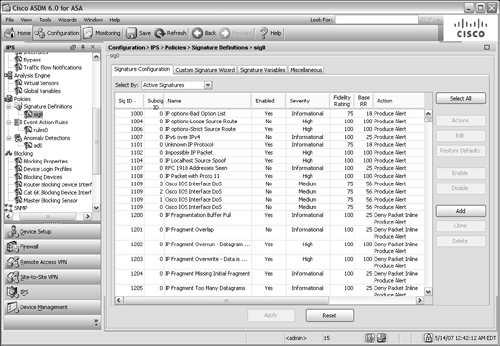
• Modify packets
• Generate an alert
• Request a reaction from a network device
• Reset the connection
Figure 12-45 shows the full set of actions that can be selected on a signature in the signature definition. The actions are predefined for each signature in the default sig0 definition, but can be overridden by configuring the signature.
The AIP has a default set of event action rules called rules0 that can be used to override or set general parameters for actions. You can edit rules0 or define your own event action rule set by selecting the Configuration tab, then the IPS link, and then the Event Action Rules link in the scrolling list under Policies.
Working with Anomaly Detection Policies
Beginning with IPS 6.0 (and ASA release 8.0), an AIP has an anomaly detection engine that can detect worm-based activity on a network. A worm is an agent that begins on one host and propagates to as many other hosts as possible. Worms spread themselves automatically by looking for other potential vulnerable targets through network scans.
Figure 12-45 Event Actions for an IPS Signature
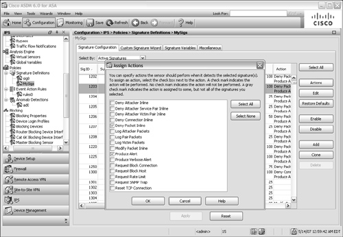
Anomaly Detection (AD) works by detecting large amounts of scanning traffic from single hosts to many others. AD looks for unidirectional User Datagram Protocol (UDP) traffic, where the worm-infected host is sending packets to many destination addresses using the same destination port, with little return traffic. With TCP, AD looks for many half-open or embryonic connections from one host to many others, using the same destination port.
The AD feature can operate in the following modes:
• Inactive mode—AD is disabled; anomalies or worm activities are not detected.
• Learn mode—AD listens to the network traffic, gathering a baseline of typical activity. This baseline is known as the knowledge base.
• Detect mode—The knowledge base is used as a threshold for worm-based activity. When the IPS sensor detects activity above the threshold, it sends alerts and takes action on the traffic. Detect mode also updates the knowledge base periodically, so it always has a current baseline of network traffic.
The AIP has a default set of anomaly detection policies called ad0. You can edit the defaults or add your own set of AD policies by selecting the Configuration tab, then IPS, and then Anomaly Detections in the scrolling list under Policies as shown in Figure 12-46.
Figure 12-46 Anomaly Detection Settings
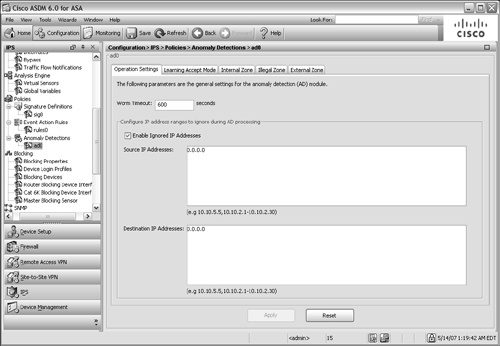
By default, the AIP runs AD in the detect mode, actively detecting and mitigating worm activity. When AD is first enabled on an IPS sensor, it runs for the first 24 hours in learn mode. After it gathers a baseline, it automatically moves to detect mode.
AIP Interfaces
The ASA and AIP are connected over the ASA chassis backplane by two hidden interfaces:
• GigabitEthernet0/0—Used only for command and control traffic between the ASA and AIP.
• GigabitEthernet0/1—Used for data transfer between the ASA and AIP; this is the only interface that can be monitored as a sensing interface by the AIP for IPS functions.
From the ASA, neither of these interfaces is available or configurable. The interfaces can be seen and used only from the AIP itself.
To perform IPS functions, an IPS platform must be able to monitor one or more of its interfaces. IPS sensor interfaces can be configured in any of the following ways:
• Promiscuous monitoring—A single interface is used to monitor traffic; the IPS sensor can make decisions on what to do with the packets, but the packets do not actually pass through the IPS.
• Inline interface—Usually two physical interfaces are configured as an inline pair, where the IPS sensor monitors traffic entering on one interface and exiting on the other.
An AIP does not have multiple physical interfaces, so you can configure only a single interface in inline mode. Packets received from the ASA on the interface are examined by the AIP. If the AIP decides to permit a packet, the packet is returned to the ASA on the same interface for forwarding. If the AIP decides to block the packet, the packet is simply not returned to the ASA at all.
• VLAN inline pair—Two VLAN interfaces are configured as an inline pair, so that the IPS sensor examines traffic entering on one VLAN interface and exiting on the other.
The ASA platform cannot use VLAN inline interface pairs because only one interface (GigabitEthernet0/1) connects the ASA and AIP over the backplane.
IPS Virtual Sensors
IPS 6.0 enables an IPS platform, such as the AIP, to define virtual sensors that can monitor traffic in a variety of ways. ASA 8.0 (1) is the first release to offer virtual sensor support in cooperation with an AIP running IPS 6.0. With virtual sensors, a single IPS hardware platform can run multiple IPS sensors, all operating independently.
An AIP can operate up to four different virtual sensors. Each of the virtual sensors must use the only interface available on the AIP—GigabitEthernet0/1. Reusing the same interface might seem to be a severe limitation. However, the AIP is able to isolate traffic to and from the virtual sensors even over the same interface.
Virtual sensors can be used in different policies within a policy map, and they can be allocated to one or more security contexts on an ASA. For example, you might customize one virtual sensor to meet the policies of a business unit and apply it to one security context. You could customize a different virtual sensor for another business unit, to be applied to a different context, and so on.
Each ASA context connects to the AIP over a different instance of backplane interface GigabitEthernet0/1. Remember that the virtual sensors are configured only on the AIP, so GigabitEthernet0/1 can be seen and manipulated only from the AIP—not from the ASA.
You can configure virtual sensors on the AIP with the following steps:
1. Configure IPS policies.
The AIP is preconfigured with the default sig0 signature definition, rules0 event action rule set, and ad0 anomaly detection policies. You can use these policies as-is, or you can make changes to them as described in the section “IPS Policies” earlier in this chapter.
The policies are applied to a sensor interface in Step 2.
2. Configure a virtual sensor.
By default, one virtual sensor is preconfigured on an AIP. The virtual sensor is called vs0 and uses the GigabitEthernet0/1 backplane AIP interface. It also has the default policies sig0, rules0, and ad0 applied to it, as shown in Figure 12-47. Notice that the backplane interface is available to the virtual sensor, but has not been assigned to the sensor yet. This is done in Step 3.
Figure 12-47 The Default vs0 Virtual Sensor
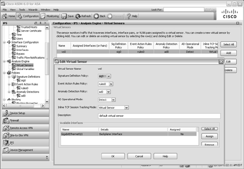
If your ASA is running in single-context security mode, you can use the default vs0 virtual sensor as it is already configured.
If your ASA is running multiple context mode and has more than one security context configured, you can use vs0 as well as any new virtual sensor that you configure in any of the contexts.
To configure a new virtual sensor, select the Configuration tab, then IPS, and then the Virtual Sensors link in the scrolling list under Analysis Engine. Click on the Add button and choose a name and policies for the sensor.
3. Assign an AIP interface to the virtual sensor.
Before a virtual sensor can be used, you need to assign an AIP interface to it. Even the default vs0 virtual sensor does not have an interface assigned until you manually configure it.
Select the Virtual Sensors link in the scrolling list under Analysis Engine and then select a virtual sensor. Next, click on the Edit button.
The Edit Virtual Sensor window is shown. Toward the bottom of the window, GigabitEthernet0/1 is shown as an available interface, but shown as No in the Assigned column. To assign the interface, click on the Assign button. (If you ever need to unassign an interface from a virtual sensor, click on the Remove button.)
In Figure 12-48, the default vs0 virtual sensor is being edited so that the GigabitEthernet0/1 interface can be assigned to it.
Figure 12-48 Assigning a Sensing Interface to a Virtual Sensor
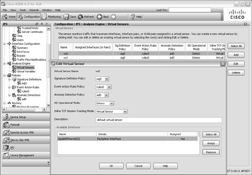
On an AIP, every virtual sensor is assigned to the GigabitEthernet0/1 backplane interface. Actually, the interface must be explicitly assigned to one virtual sensor; after that is done, it is implicitly assigned to the other virtual sensors.
Do not worry about duplicating the interface across the sensors—the ASA and AIP take care of keeping the sensors isolated to their security contexts.
4. Apply the virtual sensor to an ASA context.
If the ASA is running in multiple context mode, the virtual sensor must be mapped to a security context. Use the following command in context configuration mode:
Firewall(config-ctx)# allocate-ips sensor_name [mapped_name] [default]
The virtual sensor named sensor_name is applied to the current context. By default, the sensor name also appears in the context configuration. If you do not want a context administrator to see the actual name of the sensor, you can supply an alias as mapped_name to be seen.
Tip
The allocate-ips command is not available when the ASA is running in single context mode. In that case, the default virtual sensor vs0 is automatically applied to the ASA—even if other virtual sensors have been configured on the AIP. You can see the virtual sensor with the show ips command:
Firewall# show ipsSensor Name Sensor ID----------- ---------vs0 1Firewall#
As an example, suppose virtual sensors vs0 and vs1 have been configured on the AIP and are to be applied to security contexts Department1 and Department2, respectively. You can use the following commands to apply the virtual sensors:
Firewall(config)# context Department1
Firewall(config-ctx)# allocate-interface Ethernet0/0
Firewall(config-ctx)# allocate-interface Ethernet0/1
Firewall(config-ctx)# allocate-ips vs0 ips-a
Firewall(config-ctx)# config-url disk0:/dept1.cfg
Firewall(config-ctx)# exit
Firewall(config)# context Department2
Firewall(config-ctx)# allocate-interface Ethernet0/2
Firewall(config-ctx)# allocate-interface Ethernet0/3
Firewall(config-ctx)# allocate-ips vs1 ips-b
Firewall(config-ctx)# config-url disk0:/dept2.cfg
Firewall(config-ctx)# exit
Notice that the virtual sensors are configured with mapped names ips-a and ips-b. In the contexts, the administrators see only the mapped names:
Firewall/Department1# show ips
Sensor Name
-----------
ips-a
Firewall/Department1#
Also, you can allocate multiple virtual sensors across the contexts in any fashion, as in the following example:
Firewall(config)# context Department1
Firewall(config-ctx)# allocate-interface Ethernet0/0
Firewall(config-ctx)# allocate-interface Ethernet0/1
Firewall(config-ctx)# allocate-ips vs0 ips-a
Firewall(config-ctx)# allocate-ips vs1 ips-b
Firewall(config-ctx)# config-url disk0:/dept1.cfg
Firewall(config-ctx)# exit
Firewall(config)# context Department2
Firewall(config-ctx)# allocate-interface Ethernet0/2
Firewall(config-ctx)# allocate-interface Ethernet0/3
Firewall(config-ctx)# allocate-ips vs1 ips-a
Firewall(config-ctx)# config-url disk0:/dept2.cfg
Firewall(config-ctx)# exit
5. Configure an ASA policy map to divert traffic to virtual sensor.
By default, the ASA does not send any traffic to an IPS virtual sensor. You need to configure a policy map that matches traffic to be inspected and then apply the policy map in a service policy.
In the policy map configuration, use the following command to divert traffic to the virtual sensor:
Firewall(config)# policy-map pmap_name
Firewall(config-pmap)# class cmap_name
Firewall(config-pmap-c)# ips {promiscuous | inline} {fail-close | fail-open} [sensor
sensor_name]
Firewall(config-pmap-c)# exit
Firewall(config-pmap)# exit
The virtual sensor can be used in promiscuous or inline mode. In addition, you can configure the ASA to keep forwarding traffic normally (fail-open) or to block all traffic (fail-close) if the AIP fails.
You can give the virtual sensor name with the sensor keyword, as either the virtual sensor name or the mapped name used in the context. If you do not give the sensor keyword, the default sensor is used.
In the following example, all traffic passing through the ASA’s outside interface is diverted to virtual sensor vs0.
Firewall(config)# class-map anything
Firewall(config-cmap)# match any
Firewall(config-cmap)# exit
!
Firewall(config)# policy-map MyPolicy
Firewall(config-pmap)# class anything
Firewall(config-pmap-c)# ips inline fail-close sensor vs0
Firewall(config-pmap-c)# exit
Firewall(config-pmap)# exit
Firewall(config)# service-policy MyPolicy interface outside
If you have configured more than one virtual sensor on the AIP, you can divert different traffic to each by referencing them with multiple ips commands in the policy map.