Chapter 22
Masquerading the Original IP Address of an Internal Network Host
Any external user, whether an attacker or a legitimate Internet user, should have no visibility into your internal network. You can hide the internal addresses of your network by masquerading them into public addresses. However, assigning a dedicated public address to each of the internal hosts is not a feasible option. You can meet this challenge by enabling the Network Address Translation (NAT) functionality on an FTD device. This chapter demonstrates how to configure NAT and how NAT can masquerade an internal IP address as a public IP address.
Note
In this chapter, the terms translation and masquerading refer to the same operation and are interchangeable. In other words, translation of an address and masquerading of an address refer to the same technology: NAT.
NAT Essentials
NAT allows FTD to translate an internal IP address into an address from a different subnet. The NAT process is transparent to both internal and external hosts. When NAT is in action, an internal host is unaware that its original IP address is being translated or masqueraded to a public address, while the external host assumes that the public address is the actual address of the internal host.
Figure 22-1 shows that the NAT operations of an FTD device take place on the Firewall engine.

Another advantage of NAT is the ability to route private traffic to the Internet. Internal hosts of an organization use private IP addresses, as defined in RFC 1918. However, these addresses are not routable to the Internet unless you map or translate them into public addresses. This “limitation” of private address space actually allows different organizations to reuse the same addresses within their internal networks and to maintain them regardless of any changes of their public IP address. Thus, it conserves the use of public IP addresses.
Table 22-1 shows the range of private IP addresses and the number of available hosts in Classes A, B, and C.
Table 22-1 Private IP Addressing, as Defined in RFC 1918
Class |
Range of Private IP Addresses |
Number of Host |
Class A |
10.0.0.0–10.255.255.255 |
224 − 2 = 16,777,214 |
Class B |
172.16.0.0–172.31.255.255 |
220 − 2 = 1,048,574 |
Class C |
192.168.0.0–192.168.255.255 |
216 − 2 = 65,534 |
NAT Techniques
NAT allows you to masquerade IP addresses in various scenarios, such as one-to-one, one-to-many, many-to-one, many-to-many, few-to-many, and many-to-few. However, before you enable NAT, you need to answer the following questions:
![]() How does an FTD device select a masqueraded or translated address? Is it predefined statically or allocated dynamically?
How does an FTD device select a masqueraded or translated address? Is it predefined statically or allocated dynamically?
![]() How many external or public addresses are available for selection? One or more?
How many external or public addresses are available for selection? One or more?
Your answers to these questions can help you determine the type of translations to enable. You can categorize NAT mainly into three types:
![]() Static NAT: FTD permanently maps the original IP address with a translated IP address. Because the mapping is permanent, either the internal or an external host is able to initiate a connection.
Static NAT: FTD permanently maps the original IP address with a translated IP address. Because the mapping is permanent, either the internal or an external host is able to initiate a connection.
![]() Dynamic NAT: Instead of a permanent mapping, FTD selects an IP address from a predefined address pool and translates an original internal address into the selected IP address. The selection of an address is on a first-come, first-served basis.
Dynamic NAT: Instead of a permanent mapping, FTD selects an IP address from a predefined address pool and translates an original internal address into the selected IP address. The selection of an address is on a first-come, first-served basis.
![]() Port Address Translation (PAT): If a dynamic address pool has fewer external addresses than there are internal hosts, it is impossible for all the internal hosts to connect to external networks at the same time. To address this issue, FTD can translate both the IP address and port number of a connection (as opposed to just the IP address) and can multiplex over 65,000 connections over a single IP address.
Port Address Translation (PAT): If a dynamic address pool has fewer external addresses than there are internal hosts, it is impossible for all the internal hosts to connect to external networks at the same time. To address this issue, FTD can translate both the IP address and port number of a connection (as opposed to just the IP address) and can multiplex over 65,000 connections over a single IP address.
RFC documents describe this feature as Network Address and Port Translation (NAPT), but due to the nature of its operation, this feature is also known as Port Address Translation (PAT), NAT overload, and IP masquerading. The Firepower System calls it PAT.
Figure 22-2 shows the major differences between NAT and PAT.

FTD can use the IP address of the egress interface for PAT operation. This means that when any internal host connects to a resource over the Internet, the source IP address of the connection appears as the egress interface of the FTD device instead of as the original internal host address. However, if the number of concurrent connections exceeds its limit, any additional hosts are unable to connect to the external network. To address this issue, you can combine the PAT functionality with a dynamic address pool. This allows an FTD device to select a new IP address from the pool when the first selection from the pool is no longer available for multiplexing a new connection.
NAT Rule Types
FTD offers two options to configure a NAT rule condition:
![]() Auto NAT: An Auto NAT rule can translate one address—either a source or destination address—in a single rule. This means that to translate both source and destination addresses, two separate Auto NAT rules are necessary.
Auto NAT: An Auto NAT rule can translate one address—either a source or destination address—in a single rule. This means that to translate both source and destination addresses, two separate Auto NAT rules are necessary.
![]() Manual NAT: A Manual NAT rule allows the translation of both source and destination addresses within the same rule. A Manual NAT rule may be necessary when you want to make an exception for translation.
Manual NAT: A Manual NAT rule allows the translation of both source and destination addresses within the same rule. A Manual NAT rule may be necessary when you want to make an exception for translation.
Figure 22-3 compares the available translation options in the NAT rule editor. An Auto NAT Rule supports the translation of one address per rule, while a Manual NAT Rule allows you to translate both source and destination addresses in a single rule.

A NAT policy editor categorizes NAT rules into three groups: NAT Rules Before, Auto NAT Rules, and NAT Rules After. In the CLI, you can find the rules under Section 1, Section 2, and Section 3, respectively. During evaluation, FTD begins with the rules under Section 1. Until there is a match, FTD continues evaluating the rules in the next sections.
Any rules under the NAT Rules Before and NAT Rules After sections are part of manual NAT policies. Their names and priorities are relative to the Auto NAT Rules, which allow you to translate one type of address at a time. To translate destination addresses, a separate Auto NAT rule is necessary.
Figure 22-4 describes the priority of each section in a NAT policy.

In this chapter, you will learn how to configure Auto NAT rules with both static and dynamic types.
Best Practices for NAT Deployment
Consider the following best practices when you plan to enable NAT on an FTD device:
![]() Configuring an Auto NAT rule is simpler than configuring a Manual NAT rule. Cisco recommends that you choose an Auto NAT rule, as you can easily implement most of the common NAT scenarios with it. A Manual NAT rule may be necessary when you want to make an exception for translation.
Configuring an Auto NAT rule is simpler than configuring a Manual NAT rule. Cisco recommends that you choose an Auto NAT rule, as you can easily implement most of the common NAT scenarios with it. A Manual NAT rule may be necessary when you want to make an exception for translation.
![]() If you modify an existing NAT rule or redeploy a new NAT policy, you may find that the new policy is not in action until the timer for any existing connections expires. To have FTD act on the latest NAT policy immediately, you can clear the current translations by running the command clear xlate.
If you modify an existing NAT rule or redeploy a new NAT policy, you may find that the new policy is not in action until the timer for any existing connections expires. To have FTD act on the latest NAT policy immediately, you can clear the current translations by running the command clear xlate.
![]() The larger the translation table, the higher the processing overhead. If the number of translated connections grows excessively, it can affect the CPU and memory utilization of an FTD device.
The larger the translation table, the higher the processing overhead. If the number of translated connections grows excessively, it can affect the CPU and memory utilization of an FTD device.
![]() To improve performance, prefer static NAT to dynamic NAT or PAT.
To improve performance, prefer static NAT to dynamic NAT or PAT.
![]() Review the addresses on dynamic and static NAT rules carefully before you apply them. Avoid creating rules with overlapping IP addresses.
Review the addresses on dynamic and static NAT rules carefully before you apply them. Avoid creating rules with overlapping IP addresses.
![]() Ensure that any applications running on a network terminate connections gracefully to prevent an FTD device from handling stale connections.
Ensure that any applications running on a network terminate connections gracefully to prevent an FTD device from handling stale connections.
![]() Make sure the idle timeout values for Translation Slot (xlate) and Connection (Conn) are set for optimal performance. You can adjust the timeout values on the Platform Settings page of FTD.
Make sure the idle timeout values for Translation Slot (xlate) and Connection (Conn) are set for optimal performance. You can adjust the timeout values on the Platform Settings page of FTD.
Figure 22-5 shows the timeout values for an FTD. To find this configuration page, go to Devices > Platform Settings. You can update an existing policy or create a new one.

Fulfilling Prerequisites
Before you add a NAT rule, ensure that you have understood and fulfilled the following items:
![]() Any associated interfaces that participate in a NAT configuration have to be in a regular firewall mode. FTD does not support NAT on IPS-only interface types, such as inline, inline-tap, and passive. Figure 22-6 shows the available configuration modes for an FTD physical interface. Select None to enable the regular router interface mode, which supports NAT.
Any associated interfaces that participate in a NAT configuration have to be in a regular firewall mode. FTD does not support NAT on IPS-only interface types, such as inline, inline-tap, and passive. Figure 22-6 shows the available configuration modes for an FTD physical interface. Select None to enable the regular router interface mode, which supports NAT.

![]() If you use an FTD device in an IPS-only mode, make sure all the associated interfaces where you want to enable NAT are now configured with IP address and security zones. Figure 22-7 shows the allocation of IP addresses and security zones in FTD. The lab topology in this chapter uses three routed interfaces on FTD—GigabitEthernet1/1, GigabitEthernet1/2, and GigabitEthernet1/3.
If you use an FTD device in an IPS-only mode, make sure all the associated interfaces where you want to enable NAT are now configured with IP address and security zones. Figure 22-7 shows the allocation of IP addresses and security zones in FTD. The lab topology in this chapter uses three routed interfaces on FTD—GigabitEthernet1/1, GigabitEthernet1/2, and GigabitEthernet1/3.

![]() Before you begin the process of adding a NAT rule, define any network objects that may be invoked within a NAT rule. To add a network object, go to the Objects > Object Management page and select the Add Network menu. Figure 22-8 shows the network objects that are used in the configuration examples in this chapter. You can add any additional objects needed for your own deployment.
Before you begin the process of adding a NAT rule, define any network objects that may be invoked within a NAT rule. To add a network object, go to the Objects > Object Management page and select the Add Network menu. Figure 22-8 shows the network objects that are used in the configuration examples in this chapter. You can add any additional objects needed for your own deployment.

Configuring NAT
FTD enables you to accomplish translation in various ways. You can select any type (static versus dynamic) with any combination of NAT rule (Auto versus Manual). However, Cisco recommends that you use Auto NAT rule, as it is easier to configure and simpler to troubleshoot. In the following sections, you will learn how to configure Auto NAT to masquerade IP addresses in the following real-world deployment scenarios:
![]() Masquerading a source address when an internal host initiates a connection to an external server
Masquerading a source address when an internal host initiates a connection to an external server
![]() Allowing an external host to connect to an internal host when an external host uses a masqueraded destination address
Allowing an external host to connect to an internal host when an external host uses a masqueraded destination address
Masquerading a Source Address (Source NAT for Outbound Connection)
When an internal host initiates a connection to the Internet, FTD can translate the internal IP address to a public IP address. In other words, FTD can masquerade the source addresses of outbound connections. This section describes various methods to select a public IP address for an outbound connection.
Note
This section assumes that you have already configured any necessary objects described earlier in this chapter, in the “Fulfilling Prerequisites” section.
Figure 22-9 shows a scenario where an internal host connects to an external host through an FTD device. When an end user initiates a connection using the original source IP address, FTD translates (masquerades) the original source IP address into an address that is predefined in an address pool.

Configuring a Dynamic NAT Rule
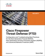
The FMC offers two types of NAT policies—Firepower NAT Policy and Threat Defense NAT Policy. The former is used to enable NAT on classic Firepower hardware, such as 7000 and 8000 Series models. To enable NAT on FTD, you need to deploy Threat Defense NAT Policy on it. To do so, follow these steps:
Step 1. Navigate to Devices > NAT. The NAT Policy window appears.
Step 2. To create a new NAT policy for an FTD device, select Threat Defense NAT Policy (see Figure 22-10).
Step 3. When the New Policy window appears, give a name to your policy and add your FTD device from the list of available devices to the policy (see Figure 22-11). Click the Save button. The NAT policy editor page appears.

Step 4. On the policy editor page, click the Add Rule button to create a NAT rule. The Add NAT Rule window appears.
Step 5. From the NAT Rule dropdown select Auto NAT Rule, and from the Type dropdown select Dynamic. Depending on your selections in both of these dropdowns, you will find different configurable options in the Translation tab. For instance, for an Auto NAT Rule with Dynamic type, you need to configure the Original Source and Translated Source.
Step 6. Use the Original Source dropdown to define the source IP addresses of the packets that you want to masquerade. You can select a network object that you defined in the section “Fulfilling Prerequisites,” earlier in this chapter. If you did not create an object earlier, you can create one on the fly by clicking the green plus icon next to a dropdown.
Step 7. Define a translated address—the address that appears as the source address of a translated packet. You need to select one of the following translation methods on the Translation or PAT Pool tab, depending on the type of NAT (static or dynamic) you want to configure.
![]() Destination Interface IP: This allows an FTD device to use the same IP address as the egress interface of an FTD.
Destination Interface IP: This allows an FTD device to use the same IP address as the egress interface of an FTD.
![]() Address: This enables an FTD device to select an address from a predefined address pool.
Address: This enables an FTD device to select an address from a predefined address pool.
Table 22-2 shows a matrix of various Auto NAT rule selections. In this section, you will implement dynamic NAT with an address pool (highlighted row).
Table 22-2 Auto NAT Rule—Major Configurable Options
Type |
Translation Tab (Translated Source) |
Translation Tab (Port Translation) |
PAT Pool Tab |
Static |
Destination Interface IP |
Configurable |
Not Configurable |
Static |
Address |
Configurable |
Not Configurable |
Dynamic |
Destination Interface IP |
Not Configurable |
Not Configurable |
Dynamic |
Address |
Not Configurable |
Unselected |
Dynamic |
Address |
Not Configurable |
Enabled with Address |
Dynamic |
Address |
Not Configurable |
Enabled with Destination Interface IP |
Figure 22-12 shows the configuration of original and translated addresses in a dynamic Auto NAT rule.

At this point, you could save the configuration and deploy the policy on the FTD device. However, you may want to consider the following optional configurations.
Step 8. On the PAT Pool tab, select Flat Port Range and Include Reserve Ports to enable an FTD device to use the complete range of port numbers, 1 to 65535, even though the same source port number is unavailable for mapping.
Step 9. On the Interface Objects tab, select the ingress and egress interfaces for the traffic you want to translate. The Available Interface Objects field shows the associated security zones that you assigned in the Devices > Devices Management page.
When you complete all the steps, click the OK button on the NAT rule editor window to create the NAT rule. The browser returns to the NAT policy editor, where you can see the NAT rule you have just created. To activate the policy, first click Save to save the policy, and then click Deploy to deploy it on your FTD device.
Figure 22-13 shows a dynamic Auto NAT rule that translates the source IP addresses of any hosts from the INSIDE_ZONE to the OUTSIDE_ZONE. The translated packet uses an address from the address pool, Pool-OUT-203.0.113.3-5, as its source IP address.

In the following sections, you will learn how to verify the configuration on the CLI and how to determine whether an FTD device is translating addresses as expected.
Verifying the Configuration
After you deploy a NAT policy, you can run the show running-config nat command in the CLI to view the latest NAT configurations and to confirm whether the desired policy is active.
Example 22-1 exhibits the running configurations of NAT and the definitions of any associated objects that are invoked in a NAT rule.
Example 22-1 Defining a NAT Rule and Any Associated Objects
! To view the NAT configurations:
> show running-config nat
!
object network Net-IN-192.168.1.0
nat (INSIDE_INTERFACE,OUTSIDE_INTERFACE) dynamic pat-pool Pool-OUT-203.0.113.3-5
flat include-reserve
>
! To determine the scope of an object:
> show running-config object
object network Net-IN-192.168.1.0
subnet 192.168.1.0 255.255.255.0
object network Pool-OUT-203.0.113.3-5
range 203.0.113.3 203.0.113.5
>
You can also run the show nat detail command to display more detailed information about a NAT policy, such as the priority of a rule (Auto NAT versus Manual NAT) or the type of a rule (static versus dynamic). The output of this command also displays the number of matching connections in both forward and reverse directions, through the translate_hits and untranslate_hits counters, respectively.
Example 22-2 shows an Auto NAT rule (dynamic PAT) for translating traffic from the 192.168.1.0/24 network to the address pool 203.0.113.3 to 203.0.113.5. The zero hit count indicates that the rule has not matched any connections.
Example 22-2 Output of the show nat detail Command
> show nat detail
Auto NAT Policies (Section 2)
1 (INSIDE_INTERFACE) to (OUTSIDE_INTERFACE) source dynamic Net-IN-192.168.1.0
pat-pool Pool-OUT-203.0.113.3-5 flat include-reserve
translate_hits = 0, untranslate_hits = 0
Source - Origin: 192.168.1.0/24, Translated (PAT): 203.0.113.3-203.0.113.5
>
Examples 22-1 and 22-2 display the source (INSIDE_INTERFACE) and destination (OUTSIDE_INTERFACE) defined in a NAT rule. However, the output in these examples does not show the status, IP address, or name of an interface. You can find them by running other commands, such as show nameif and show interfaces ip brief.
Example 22-3 shows how to map the physical interfaces with their logical names. It also shows how to verify the IP address and status of an interface.
Example 22-3 Viewing Various Parameters of FTD Interfaces
! To view the mapping of physical interfaces with their logical names:
> show nameif
Interface Name Security
GigabitEthernet1/1 INSIDE_INTERFACE 0
GigabitEthernet1/2 OUTSIDE_INTERFACE 0
GigabitEthernet1/3 DMZ_INTERFACE 0
Management1/1 diagnostic 0
>
! To view the status and IP addresses of the FTD interfaces:
> show interface ip brief
Interface IP-Address OK? Method Status Protocol
Virtual0 127.1.0.1 YES unset up up
GigabitEthernet1/1 192.168.1.1 YES CONFIG up up
GigabitEthernet1/2 203.0.113.1 YES CONFIG up up
GigabitEthernet1/3 172.16.1.1 YES CONFIG up up
GigabitEthernet1/4 unassigned YES unset administratively down down
GigabitEthernet1/5 unassigned YES unset administratively down down
.
.
<Output omitted for brevity>
Verifying the Operation: Inside to Outside
This section describes how to verify the NAT operation on an FTD device. To demonstrate the translation process, this example uses SSH traffic.
Let’s initiate a connection from an internal host 192.168.1.10 to an external SSH server 203.0.113.10. If NAT is operational on FTD, the external SSH server sees 203.0.113.3 as the source IP address of the internal host instead of its original source IP address, 192.168.1.10.
Example 22-4 shows an SSH connection between the internal client and the external server. The connection table shows the original IP address (192.168.1.10) of the internal server with a translation (xlate) ID. However, you can determine the masqueraded or translated address (203.0.113.3) from the translation table.
Example 22-4 Connection and Translation Table
> show conn detail
1 in use, 4 most used
Flags: A - awaiting responder ACK to SYN, a - awaiting initiator ACK to SYN,
b - TCP state-bypass or nailed,
C - CTIQBE media, c - cluster centralized,
D - DNS, d - dump, E - outside back connection, e - semi-distributed,
F - initiator FIN, f - responder FIN,
G - group, g - MGCP, H - H.323, h - H.225.0, I - initiator data,
i - incomplete, J - GTP, j - GTP data, K - GTP t3-response
k - Skinny media, M - SMTP data, m - SIP media, N - inspected by Snort,
n - GUP
O - responder data, P - inside back connection,
q - SQL*Net data, R - initiator acknowledged FIN,
R - UDP SUNRPC, r - responder acknowledged FIN,
T - SIP, t - SIP transient, U - up,
V - VPN orphan, v - M3UA W - WAAS,
w - secondary domain backup,
X - inspected by service module,
x - per session, Y - director stub flow, y - backup stub flow,
Z - Scansafe redirection, z - forwarding stub flow
TCP OUTSIDE_INTERFACE: 203.0.113.10/22 INSIDE_INTERFACE: 192.168.1.10/41934,
flags UxIO N, idle 6s, uptime 18s, timeout 1h0m, bytes 6718, xlate id
0x7f516987ee00
>
> show xlate detail
1 in use, 2 most used
Flags: D - DNS, e - extended, I - identity, i - dynamic, r - portmap,
s - static, T - twice, N - net-to-net
TCP PAT from INSIDE_INTERFACE:192.168.1.10/41934 to OUTSIDE_INTER-
FACE:203.0.113.3/41934 flags ri idle 0:00:28 timeout 0:00:30 refcnt 1 xlate id
0x7f516987ee00
>
By looking at the output of the show nat detail command, you can determine whether the traffic matches a particular NAT rule and how many times a rule finds a match.
Example 22-5 confirms that the Auto NAT rule found one matching connection when a host sent traffic from INSIDE_INTERFACE to OUTSIDE_INTERFACE.
Example 22-5 Matching One Connection in the Forward Direction
> show nat detail
Auto NAT Policies (Section 2)
1 (INSIDE_INTERFACE) to (OUTSIDE_INTERFACE) source dynamic Net-IN-192.168.1.0 pat-pool Pool-OUT-203.0.113.3-5 flat include-reserve
translate_hits = 1, untranslate_hits = 0
Source - Origin: 192.168.1.0/24, Translated (PAT): 203.0.113.3-203.0.113.5
>
By capturing the traffic in real time when an address is translated, you can analyze the FTD operation during address translation.
Example 22-6 demonstrates the capture of any SSH traffic on the inside interface. Later, you will analyze the translation of these packets.
Example 22-6 Capturing SSH Traffic on the FTD Inside Interface
! Begin the capture of SSH traffic on inside interface.
> capture ssh_traffic_inside trace interface INSIDE_INTERFACE match tcp any any
eq 22
! Verify if the FTD is running a capture for SSH traffic.
> show capture
capture ssh_traffic_inside type raw-data trace interface INSIDE_INTERFACE
[Capturing - 0 bytes]
match tcp any any eq ssh
>
At this stage, you can initiate an SSH connection from the internal host to the external SSH server. FTD should capture the traffic on the inside interface. You can view the packets in the CLI.
Example 22-7 shows the first few captured packets for an SSH connection. Later, it analyzes the first packet to demonstrate the detailed operation of an address translation.
Example 22-7 Analyzing Captured Packets
! To view all of the captured packets (press Ctrl+C to exit from a long show):
> show capture ssh_traffic_inside
81 packets captured
1: 02:59:47.220310 192.168.1.10.41934 > 203.0.113.10.22: S
1482617093:1482617093(0) win 29200 <mss 1460,sackOK,timestamp 15243390
0,nop,wscale 7>
2: 02:59:47.221149 203.0.113.10.22 > 192.168.1.10.41934: S
1409789153:1409789153(0) ack 1482617094 win 28960 <mss 1380,sackOK,timestamp
17762742 15243390,nop,wscale 7>
3: 02:59:47.221256 192.168.1.10.41934 > 203.0.113.10.22: . ack 1409789154
win 229 <nop,nop,timestamp 15243390 17762742>
4: 02:59:47.221729 192.168.1.10.41934 > 203.0.113.10.22: P
1482617094:1482617135(41) ack 1409789154 win 229 <nop,nop,timestamp 15243391
17762742>
5: 02:59:47.222186 203.0.113.10.22 > 192.168.1.10.41934: . ack 1482617135
win 227 <nop,nop,timestamp 17762742 15243391>
.
.
<Output is omitted for brevity>
! To analyze the first captured packet:
> show capture ssh_traffic_inside packet-number 1 trace
81 packets captured
1: 02:59:47.220310 192.168.1.10.41934 > 203.0.113.10.22: S
1482617093:1482617093(0) win 29200 <mss 1460,sackOK,timestamp 15243390
0,nop,wscale 7>
Phase: 1
Type: CAPTURE
Subtype:
Result: ALLOW
Config:
Additional Information:
MAC Access list
Phase: 2
Type: ACCESS-LIST
Subtype:
Result: ALLOW
Config:
Implicit Rule
Additional Information:
MAC Access list
Phase: 3
Type: ROUTE-LOOKUP
Subtype: Resolve Egress Interface
Result: ALLOW
Config:
Additional Information:
found next-hop 203.0.113.10 using egress ifc OUTSIDE_INTERFACE
Phase: 4
Type: ACCESS-LIST
Subtype: log
Result: ALLOW
Config:
access-group CSM_FW_ACL_ global
access-list CSM_FW_ACL_ advanced permit ip any any rule-id 268435457
access-list CSM_FW_ACL_ remark rule-id 268435457: ACCESS POLICY: AC Policy -
Mandatory/1
access-list CSM_FW_ACL_ remark rule-id 268435457: L7 RULE: Traffic Selection
Additional Information:
This packet will be sent to snort for additional processing where a verdict will be
reached
Phase: 5
Type: CONN-SETTINGS
Subtype:
Result: ALLOW
Config:
class-map class-default
match any
policy-map global_policy
class class-default
set connection advanced-options UM_STATIC_TCP_MAP
service-policy global_policy global
Additional Information:
Phase: 6
Type: NAT
Subtype:
Result: ALLOW
Config:
object network Net-IN-192.168.1.0
nat (INSIDE_INTERFACE,OUTSIDE_INTERFACE) dynamic pat-pool Pool-OUT-203.0.113.3-5
flat include-reserve
Additional Information:
Dynamic translate 192.168.1.10/41934 to 203.0.113.3/41934
Phase: 7
Type: NAT
Subtype: per-session
Result: ALLOW
Config:
Additional Information:
Phase: 8
Type: IP-OPTIONS
Subtype:
Result: ALLOW
Config:
Additional Information:
Phase: 9
Type: NAT
Subtype: per-session
Result: ALLOW
Config:
Additional Information:
Phase: 10
Type: IP-OPTIONS
Subtype:
Result: ALLOW
Config:
Additional Information:
Phase: 11
Type: FLOW-CREATION
Subtype:
Result: ALLOW
Config:
Additional Information:
New flow created with id 442, packet dispatched to next module
Phase: 12
Type: EXTERNAL-INSPECT
Subtype:
Result: ALLOW
Config:
Additional Information:
Application: 'SNORT Inspect'
Phase: 13
Type: SNORT
Subtype:
Result: ALLOW
Config:
Additional Information:
Snort Verdict: (pass-packet) allow this packet
Phase: 14
Type: ROUTE-LOOKUP
Subtype: Resolve Egress Interface
Result: ALLOW
Config:
Additional Information:
found next-hop 203.0.113.10 using egress ifc OUTSIDE_INTERFACE
Phase: 15
Type: ADJACENCY-LOOKUP
Subtype: next-hop and adjacency
Result: ALLOW
Config:
Additional Information:
adjacency Active
next-hop mac address 0023.2472.1d3c hits 139985869104448
Phase: 16
Type: CAPTURE
Subtype:
Result: ALLOW
Config:
Additional Information:
MAC Access list
Result:
input-interface: OUTSIDE_INTERFACE
input-status: up
input-line-status: up
output-interface: OUTSIDE_INTERFACE
output-status: up
output-line-status: up
Action: allow
1 packet shown
>
Verifying the Operation: Outside to Inside
The NAT rule you created earlier evaluates the forward traffic—the traffic that originates from INSIDE_INTERFACE and is destined for OUTSIDE_INTERFACE. However, any traffic in the reverse direction does not match this rule. You can verify this by capturing SSH traffic on OUTSIDE_INTERFACE and by analyzing the trace data.
Example 22-8 shows how to enable the capture tool on the outside interface.
Example 22-8 Capturing SSH Traffic on the FTD OUTSIDE_INTERFACE
! Enable capture on the outside interface:
> capture ssh_traffic_outside trace interface OUTSIDE_INTERFACE match tcp any any
eq 22
! FTD begins capturing SSH traffic on the outside interface:
> show capture
capture ssh_traffic_inside type raw-data trace interface INSIDE_INTERFACE
[Capturing - 0 bytes]
match tcp any any eq ssh
capture ssh_traffic_outside type raw-data trace interface OUTSIDE_INTERFACE
[Capturing - 0 bytes]
match tcp any any eq ssh
>
Now if you attempt to connect from an external host to an internal host, regardless of the destination IP address you choose—either original or masqueraded—the connection attempt fails.
Example 22-9 shows the failed connection attempts from the external host 203.0.113.10 to the same internal host—through the masqueraded IP address 203.0.113.3 and the original IP address 192.168.1.10.22.
Example 22-9 Captured Traffic on the FTD OUTSIDE_INTERFACE Shows Only SYN (S) Packets
> show capture ssh_traffic_outside
8 packets captured
1: 03:56:51.100290 203.0.113.10.48400 > 203.0.113.3.22: S
3636330443:3636330443(0) win 29200 <mss 1460,sackOK,timestamp 18618684
0,nop,wscale 7>
2: 03:56:52.097269 203.0.113.10.48400 > 203.0.113.3.22: S
3636330443:3636330443(0) win 29200 <mss 1460,sackOK,timestamp 18618934
0,nop,wscale 7>
3: 03:56:54.101343 203.0.113.10.48400 > 203.0.113.3.22: S
3636330443:3636330443(0) win 29200 <mss 1460,sackOK,timestamp 18619435
0,nop,wscale 7>
4: 03:56:58.105478 203.0.113.10.48400 > 203.0.113.3.22: S
3636330443:3636330443(0) win 29200 <mss 1460,sackOK,timestamp 18620436
0,nop,wscale 7>
5: 03:57:22.069759 203.0.113.10.53048 > 192.168.1.10.22: S
1744936567:1744936567(0) win 29200 <mss 1460,sackOK,timestamp 18626426
0,nop,wscale 7>
6: 03:57:23.066250 203.0.113.10.53048 > 192.168.1.10.22: S
1744936567:1744936567(0) win 29200 <mss 1460,sackOK,timestamp 18626676
0,nop,wscale 7>
7: 03:57:25.070369 203.0.113.10.53048 > 192.168.1.10.22: S
1744936567:1744936567(0) win 29200 <mss 1460,sackOK,timestamp 18627177
0,nop,wscale 7>
8: 03:57:29.082469 203.0.113.10.53048 > 192.168.1.10.22: S
1744936567:1744936567(0) win 29200 <mss 1460,sackOK,timestamp 18628180
0,nop,wscale 7>
8 packets shown
>
Example 22-10 analyzes the trace data of the first captured packet, where the external host tries to connect to the internal host using its masqueraded IP address, 203.0.113.3.
Example 22-10 Trying to Connect to the Masqueraded IP Address of an Internal Host
> show capture ssh_traffic_outside packet-number 1 trace
8 packets captured
1: 03:56:51.100290 203.0.113.10.48400 > 203.0.113.3.22: S
3636330443:3636330443(0) win 29200 <mss 1460,sackOK,timestamp 18618684
0,nop,wscale 7>
Phase: 1
Type: CAPTURE
Subtype:
Result: ALLOW
Config:
Additional Information:
MAC Access list
Phase: 2
Type: ACCESS-LIST
Subtype:
Result: ALLOW
Config:
Implicit Rule
Additional Information:
MAC Access list
Phase: 3
Type: ROUTE-LOOKUP
Subtype: Resolve Egress Interface
Result: ALLOW
Config:
Additional Information:
found next-hop 203.0.113.3 using egress ifc OUTSIDE_INTERFACE
Result:
input-interface: OUTSIDE_INTERFACE
input-status: up
input-line-status: up
output-interface: OUTSIDE_INTERFACE
output-status: up
output-line-status: up
Action: drop
Drop-reason: (nat-no-xlate-to-pat-pool) Connection to PAT address without pre-exis-
ting xlate
1 packet shown
>
Example 22-11 analyzes the trace data of the fifth captured packet where the external host tries to connect to the internal host by using its original IP address, 192.168.1.10.
Example 22-11 Trying to Connect to the Original IP Address of an Internal Host
> show capture ssh_traffic_outside packet-number 5 trace
8 packets captured
5: 03:57:22.069759 203.0.113.10.53048 > 192.168.1.10.22: S 1744936567:
1744936567(0) win 29200 <mss 1460,sackOK,timestamp 18626426 0,nop,wscale 7>
Phase: 1
Type: CAPTURE
Subtype:
Result: ALLOW
Config:
Additional Information:
MAC Access list
Phase: 2
Type: ACCESS-LIST
Subtype:
Result: ALLOW
Config:
Implicit Rule
Additional Information:
MAC Access list
Phase: 3
Type: ROUTE-LOOKUP
Subtype: Resolve Egress Interface
Result: ALLOW
Config:
Additional Information:
found next-hop 192.168.1.10 using egress ifc INSIDE_INTERFACE
Phase: 4
Type: ACCESS-LIST
Subtype: log
Result: ALLOW
Config:
access-group CSM_FW_ACL_ global
access-list CSM_FW_ACL_ advanced permit ip any any rule-id 268435457
access-list CSM_FW_ACL_ remark rule-id 268435457: ACCESS POLICY: AC Policy -
Mandatory/1
access-list CSM_FW_ACL_ remark rule-id 268435457: L7 RULE: Traffic Selection
Additional Information:
This packet will be sent to snort for additional processing where a verdict will be
reached
Phase: 5
Type: CONN-SETTINGS
Subtype:
Result: ALLOW
Config:
class-map class-default
match any
policy-map global_policy
class class-default
set connection advanced-options UM_STATIC_TCP_MAP
service-policy global_policy global
Additional Information:
Phase: 6
Type: NAT
Subtype: per-session
Result: ALLOW
Config:
Additional Information:
Phase: 7
Type: IP-OPTIONS
Subtype:
Result: ALLOW
Config:
Additional Information:
Phase: 8
Type: NAT
Subtype: rpf-check
Result: DROP
Config:
object network Net-IN-192.168.1.0
nat (INSIDE_INTERFACE,OUTSIDE_INTERFACE) dynamic pat-pool Pool-OUT-203.0.113.3-5
flat include-reserve
Additional Information:
Result:
input-interface: OUTSIDE_INTERFACE
input-status: up
input-line-status: up
output-interface: INSIDE_INTERFACE
output-status: up
output-line-status: up
Action: drop
Drop-reason: (acl-drop) Flow is denied by configured rule
1 packet shown
>
Connecting to a Masqueraded Destination (Destination NAT for Inbound Connection)
When external hosts access any services of your company, they should access through the public IP address of your organization. Any internal addressing scheme must be invisible to the external users. In this section, you will learn how to connect to an internal host by using a masqueraded public IP address.
Figure 22-14 illustrates a scenario where an external host connects to an internal DMZ server of a company. When an external host initiates a connection to a masqueraded public address, FTD translates the address into an internal original address.

Configuring a Static NAT Rule
Because in the previous section you created an Auto NAT rule with dynamic type and analyzed its detailed operation, this section does not duplicate the same procedures for creating a NAT policy from scratch. You can just add a new NAT rule as illustrated in Figure 22-15 and then redeploy the NAT policy. If the policy deployment is successful, FTD should let an external host connect to an internal DMZ server using a masqueraded public IP address. Because the FTD in this case translates a public destination address to an internal address, this translation is known as destination NAT.

Figure 22-15 illustrates a static NAT rule that enables an outside host to connect to a DMZ server (internal IP address 172.16.1.10) via SSH service (internal port 22) without knowing the internal addressing scheme. The outside host can access the DMZ server only if the outside host uses the masqueraded IP address 203.0.113.2 and port 2200 as its destination.
Figure 22-16 shows two rules in a NAT policy—the static Auto NAT rule (bottom) has just been created to translate inbound connections. The dynamic NAT rule (top) was added earlier to translate outbound connections.

After you add a new NAT rule, you must click the Save and Deploy buttons to enable the new NAT policy on your FTD device.
Verifying the Operation: Outside to DMZ
This section demonstrates the operation of a static Auto NAT rule on an FTD device. As in the previous exercise, this one also uses SSH service to generate traffic. However, unlike in the previous exercise, the SSH connection is initiated by an external host.
Before you begin, you should clear the NAT counters and any existing translations so that you will be able to notice any new changes quickly:
> clear nat counters
> clear xlate
Now you can try to access the internal DMZ server from an external host. Using an SSH client, connect to port 2200 of the translated (masqueraded) IP address 203.0.113.2. You will be connected to the internal DMZ server, although the original IP address of the server is 172.16.1.10, and the server listens to port 22 for SSH connections. This happens due to the static NAT on the FTD device.
Example 22-12 shows confirmation that the inbound SSH traffic matches the first rule on the Auto NAT policy. The untranslate_hits counter confirms the matching of one connection in the reverse direction.
Example 22-12 Matching a Connection in the Reverse Direction
> show nat detail
Auto NAT Policies (Section 2)
1 (DMZ_INTERFACE) to (OUTSIDE_INTERFACE) source static Serv-Real-172.16.1.10
Serv-Mask-203.0.113.2 service tcp ssh 2200
translate_hits = 0, untranslate_hits = 1
Source - Origin: 172.16.1.10/32, Translated: 203.0.113.2/32
Service - Protocol: tcp Real: ssh Mapped: 2200
2 (INSIDE_INTERFACE) to (OUTSIDE_INTERFACE) source dynamic Net-IN-192.168.1.0
pat-pool Pool-OUT-203.0.113.3-5 flat include-reserve
translate_hits = 0, untranslate_hits = 0
Source - Origin: 192.168.1.0/24, Translated (PAT): 203.0.113.3-203.0.113.5
>
Example 22-13 shows the status of the current translations. The flag confirms a static port translation between an external host and an internal DMZ server.
Example 22-13 Real-time Translation Status
> show xlate detail
1 in use, 2 most used
Flags: D - DNS, e - extended, I - identity, i - dynamic, r - portmap,
s - static, T - twice, N - net-to-net
TCP PAT from DMZ_INTERFACE:172.16.1.10 22-22 to OUTSIDE_INTERFACE:203.0.113.2
2200-2200
flags sr idle 0:00:54 timeout 0:00:00 refcnt 1 xlate id 0x7f516987ee00
>
To better understand the NAT operation, you can capture SSH traffic on an outside interface (on the translated port) and analyze it (see Example 22-14).
Example 22-14 Capturing SSH Traffic on an Outside Interface (on a Translated Port)
! Enable capture on outside interface:
> capture ssh_traffic_outside_masked trace interface OUTSIDE_INTERFACE match tcp any
any eq 2200
! Verify that the capture is running:
> show capture
capture ssh_traffic_inside type raw-data trace interface INSIDE_INTERFACE
[Capturing - 0 bytes]
match tcp any any eq ssh
capture ssh_traffic_outside type raw-data trace interface OUTSIDE_INTERFACE
[Capturing - 0 bytes]
match tcp any any eq ssh
capture ssh_traffic_outside_masked type raw-data trace interface OUTSIDE_INTERFACE
[Capturing - 0 bytes]
match tcp any any eq 2200
>
! Now, initiate an SSH connection from the external host to the internal DMZ
server. Use the masqueraded IP address and port number. It generates the following
traffic.
> show capture ssh_traffic_outside_masked
59 packets captured
1: 05:21:23.785436 203.0.113.10.41760 > 203.0.113.2.2200: S
2089153959:2089153959(0) win 29200 <mss 1460,sackOK,timestamp 19887065
0,nop,wscale 7>
2: 05:21:23.786168 203.0.113.2.2200 > 203.0.113.10.41760: S
29917599:29917599(0) ack 2089153960 win 28960 <mss 1380,sackOK,timestamp 19892875
19887065,nop,wscale 7>
3: 05:21:23.786336 203.0.113.10.41760 > 203.0.113.2.2200: . ack 29917600
win 229 <nop,nop,timestamp 19887065 19892875>
4: 05:21:23.786855 203.0.113.10.41760 > 203.0.113.2.2200: P
2089153960:2089154001(41) ack 29917600 win 229 <nop,nop,timestamp
19887066 19892875>
5: 05:21:23.787312 203.0.113.2.2200 > 203.0.113.10.41760: . ack 2089154001
win 227 <nop,nop,timestamp 19892876 19887066>
.
.
<Output is omitted for brevity>
Example 22-15 shows how to analyze the tracing data of a captured packet. FTD translates and allows the packet as you are connecting through IP address 203.0.113.2 and port 2200.
Example 22-15 Analyzing a Translated Packet (Where the Packet Matches a Rule)
> show capture ssh_traffic_outside_masked packet-number 1 trace
59 packets captured
1: 05:21:23.785436 203.0.113.10.41760 > 203.0.113.2.2200: S
2089153959:2089153959(0) win 29200 <mss 1460,sackOK,timestamp 19887065
0,nop,wscale 7>
Phase: 1
Type: CAPTURE
Subtype:
Result: ALLOW
Config:
Additional Information:
MAC Access list
Phase: 2
Type: ACCESS-LIST
Subtype:
Result: ALLOW
Config:
Implicit Rule
Additional Information:
MAC Access list
Phase: 3
Type: UN-NAT
Subtype: static
Result: ALLOW
Config:
object network Serv-Real-172.16.1.10
nat (DMZ_INTERFACE,OUTSIDE_INTERFACE) static Serv-Mask-203.0.113.2 service
tcp ssh 2200
Additional Information:
NAT divert to egress interface DMZ_INTERFACE
Untranslate 203.0.113.2/2200 to 172.16.1.10/22
Phase: 4
Type: ACCESS-LIST
Subtype: log
Result: ALLOW
Config:
access-group CSM_FW_ACL_ global
access-list CSM_FW_ACL_ advanced permit ip any any rule-id 268435457
access-list CSM_FW_ACL_ remark rule-id 268435457: ACCESS POLICY: AC
Policy - Mandatory/1
access-list CSM_FW_ACL_ remark rule-id 268435457: L7 RULE: Traffic Selection
Additional Information:
This packet will be sent to snort for additional processing where a verdict will be
reached
Phase: 5
Type: CONN-SETTINGS
Subtype:
Result: ALLOW
Config:
class-map class-default
match any
policy-map global_policy
class class-default
set connection advanced-options UM_STATIC_TCP_MAP
service-policy global_policy global
Additional Information:
Phase: 6
Type: NAT
Subtype: per-session
Result: ALLOW
Config:
Additional Information:
Phase: 7
Type: IP-OPTIONS
Subtype:
Result: ALLOW
Config:
Additional Information:
Phase: 8
Type: NAT
Subtype: rpf-check
Result: ALLOW
Config:
object network Serv-Real-172.16.1.10
nat (DMZ_INTERFACE,OUTSIDE_INTERFACE) static Serv-Mask-203.0.113.2 service tcp
ssh 2200
Additional Information:
Phase: 9
Type: NAT
Subtype: per-session
Result: ALLOW
Config:
Additional Information:
Phase: 10
Type: IP-OPTIONS
Subtype:
Result: ALLOW
Config:
Additional Information:
Phase: 11
Type: FLOW-CREATION
Subtype:
Result: ALLOW
Config:
Additional Information:
New flow created with id 505, packet dispatched to next module
Phase: 12
Type: EXTERNAL-INSPECT
Subtype:
Result: ALLOW
Config:
Additional Information:
Application: 'SNORT Inspect'
Phase: 13
Type: SNORT
Subtype:
Result: ALLOW
Config:
Additional Information:
Snort Verdict: (pass-packet) allow this packet
Phase: 14
Type: ROUTE-LOOKUP
Subtype: Resolve Egress Interface
Result: ALLOW
Config:
Additional Information:
found next-hop 172.16.1.10 using egress ifc DMZ_INTERFACE
Phase: 15
Type: ADJACENCY-LOOKUP
Subtype: next-hop and adjacency
Result: ALLOW
Config:
Additional Information:
adjacency Active
next-hop mac address a4ba.db9f.9460 hits 5205
Result:
input-interface: OUTSIDE_INTERFACE
input-status: up
input-line-status: up
output-interface: DMZ_INTERFACE
output-status: up
output-line-status: up
Action: allow
1 packet shown
>
Instead of using the translated address, if you attempt to connect using the original IP address, the connection attempt should fail. To verify it, you can use the command shown in Example 22-16, which analyzes the tracing data of a captured packet. FTD captures the packet when an external host attempts to connect to the internal DMZ server using its original IP address, but the attempt fails.
Example 22-16 Analyzing a Packet (Where the Packet Does Not Match a Rule)
> show capture ssh_traffic_outside packet-number 1 trace
6 packets captured
1: 05:19:16.438255 203.0.113.10.48556 > 172.16.1.10.22:
S 1315278899:1315278899(0) win 29200 <mss 1460,sackOK,timestamp 19855229
0, nop,wscale 7>
Phase: 1
Type: CAPTURE
Subtype:
Result: ALLOW
Config:
Additional Information:
MAC Access list
Phase: 2
Type: ACCESS-LIST
Subtype:
Result: ALLOW
Config:
Implicit Rule
Additional Information:
MAC Access list
Phase: 3
Type: ROUTE-LOOKUP
Subtype: Resolve Egress Interface
Result: ALLOW
Config:
Additional Information:
found next-hop 172.16.1.10 using egress ifc DMZ_INTERFACE
Phase: 4
Type: ACCESS-LIST
Subtype: log
Result: ALLOW
Config:
access-group CSM_FW_ACL_ global
access-list CSM_FW_ACL_ advanced permit ip any any rule-id 268435457
access-list CSM_FW_ACL_ remark rule-id 268435457: ACCESS POLICY: AC
Policy - Mandatory/1
access-list CSM_FW_ACL_ remark rule-id 268435457: L7 RULE: Traffic Selection
Additional Information:
This packet will be sent to snort for additional processing where a verdict will be
reached
Phase: 5
Type: CONN-SETTINGS
Subtype:
Result: ALLOW
Config:
class-map class-default
match any
policy-map global_policy
class class-default
set connection advanced-options UM_STATIC_TCP_MAP
service-policy global_policy global
Additional Information:
Phase: 6
Type: NAT
Subtype: per-session
Result: ALLOW
Config:
Additional Information:
Phase: 7
Type: IP-OPTIONS
Subtype:
Result: ALLOW
Config:
Additional Information:
Phase: 8
Type: NAT
Subtype: rpf-check
Result: DROP
Config:
object network Serv-Real-172.16.1.10
nat (DMZ_INTERFACE,OUTSIDE_INTERFACE) static Serv-Mask-203.0.113.2 service tcp
ssh 2200
Additional Information:
Result:
input-interface: OUTSIDE_INTERFACE
input-status: up
input-line-status: up
output-interface: DMZ_INTERFACE
output-status: up
output-line-status: up
Action: drop
Drop-reason: (acl-drop) Flow is denied by configured rule
1 packet shown
>
Summary
This chapter describes various types of NAT on an FTD device. It shows the steps to configure a NAT rule and demonstrates how FTD can leverage NAT technology to masquerade internal IP addresses in a real-world scenario.
Quiz
1. Which NAT technique allows you to translate one external destination IP address to multiple internal hosts?
a. Static NAT
b. Dynamic NAT
c. PAT
d. All of the above
2. Which NAT section has highest priority during rule evaluation?
a. NAT Rules Before
b. Auto NAT Rules
c. NAT Rules After
d. All of them have the same priority
3. Which command enables you to determine whether a connection matches a NAT rule and how many times it has matched?
a. show nat
b. show nat detail
c. show xlate detail
d. show conn detail
4. After you deploy a new NAT policy, if a connection still uses a rule from the prior version of the NAT policy, how could you ensure that FTD will use the new policy?
a. Deploy the NAT policy one more time.
b. Make the NAT rule more specific.
c. Clear the current translation table.
d. All of the above.