Chapter 4. Making Sense of All the Cisco NAC Appliance Design Options
This chapter covers the following topics:
- NAC Design Considerations
- Deployment Options
- In-Band Mode
- Out-of-Band Mode
- Clean Access Agent and Web Login with Network Scanner
In the previous chapter, you explored all the pieces, or building blocks, that can make up a Cisco NAC Appliance deployment. Now you will learn the multiple ways you can manipulate these building blocks so that they best fit into your environment. Given the complexity of today's networks, you need a Network Admission Control (NAC) solution that has options. Cisco NAC Appliance definitely has options. It has so many, in fact, that sometimes it can get confusing as to what to use where and why. The purpose of this chapter is to guide you through the different modes of operation and deployment that are available to you. Along the way, you receive explanations of the criteria you can use to make a use-case decision for various features.
This chapter starts with a brief explanation of the different Cisco NAC Appliance design decisions you will have to make. Then it moves into explaining, in detail, what each design element has to offer (depending on where you use it). Finally, it covers several traffic and work flow examples of common NAC Appliance deployment types.
NAC Design Considerations
When working through the design process for Cisco NAC Appliance, you will come up against multiple choices. Understanding what choices are available and how they work is incredibly important. Your environment will most likely use a few different deployment options, not a single one throughout. For example, you might choose to use Single-Sign-On (SSO) for your virtual private network (VPN) users but not for your wireless guest user and public space areas. Knowing how to best match the flexibility of NAC Appliance to your environment will make the deployment and adoption go smoothly.
These are some of the design decisions you will have to make in your environment:
- User Single-Sign-On versus dedicated NAC Appliance login
- In-Band versus Out-of-Band modes
- Layer 2 versus Layer 3 client adjacency
- Virtual Gateway versus Real IP Gateway modes
- Clean Access Agent versus Web Login with Network Scanner
Before explaining the specifics of each of the preceding features, it is useful to first describe the purpose of each new term or technology that will be relevant to subsequent discussions.
Single-Sign-On Capabilities
Single-Sign-On, or SSO, gives users the convenience of only having to log in to the network once. The way this works in a Cisco NAC Appliance solution is based on a trust model. For example, if a VPN concentrator has validated your login credentials successfully, NAC Appliance will trust these same credentials for its own user validation. This prevents the user from having to log in once to the VPN concentrator and a second time to NAC Appliance. Whenever possible, you should use SSO. Using SSO will greatly increase the satisfaction of the users' experience with NAC Appliance.
NAC Appliance has SSO integration support with the following platforms:
- Microsoft Active Directory (AD).
- Cisco VPN.
- Any VPN solution that can send a RADIUS accounting packet in an RFC-compliant format. (Microsoft's Internet Authentication Service is an example of this.)
- Cisco Wireless using lightweight access point technology.
In-Band Versus Out-of-Band Overview
In-Band (IB) and Out-of-Band (OOB) are modes of operation you choose for your NAC Appliance Servers. NAC Appliance Server can run in only one mode, not both simultaneously. However, a single NAC Appliance Manager can control servers of both mode types. NAC Appliance Server is similar in function, placement, and operation to a traditional stateless packet-filtering firewall. Like a firewall, NAC Appliance Server must be logically or physically in the traffic flow to work. Resembling a firewall, NAC Appliance Server's job is to regulate who and what can pass from the untrusted networks to the trusted networks. But unlike a firewall, you can choose to remove NAC Appliance Server from the traffic flow after its work—that is, posture assessment—is complete. This means NAC Appliance Server is now out-of-band. If you choose not to remove NAC Appliance Server after the host is certified, it is said to be in-band.
Configuring NAC Appliance Server for In-Band mode means that it is always in the flow of traffic between the untrusted networks and the trusted networks. This is regardless of whether or not the host on the untrusted side has passed assessment.
Configuring NAC Appliance Server for Out-of-Band mode means that it is not always in the flow of traffic. NAC Appliance Server remains in the flow of traffic between the untrusted networks and trusted networks until the host passes authentication and assessment. After a host is considered "clean," or certified, NAC Appliance reconfigures the host's switch port to be on a new VLAN. The new VLAN no longer has NAC Appliance Server in its path. Given that NAC Appliance Server is no longer in the path, network traffic to and from the certified host is routed and switched normally.
The choice of which mode to use, In-Band or Out-of-Band, will vary based on your environment and network. Like most of the choices you will make, this one is both function and location dependent. It is possible, even likely, that you will end up with both In-Band and Out-of-Band mode NAC Appliance Servers running in your deployment.
Layer 2 Versus Layer 3 Client Adjacency Overview
Layer 2 Adjacency means that NAC Appliance Server is a Layer 2 hop from hosts on its untrusted networks side. This allows NAC Appliance Server to see the real MAC address of every client it is controlling. In Layer 2 mode, a host's unique identity is defined using its MAC address only.
Layer 3 Adjacency means NAC Appliance Server is one or more Layer 3 network hops from the hosts on its untrusted networks side. In this mode, NAC Appliance Server cannot see the real MAC address of the host. In Layer 3 mode, a host's unique identity is defined using its IP address only. When using OOB mode, the client's MAC address is forwarded to NAC Appliance Server using either Clean Access Agent or the ActiveX or Java web login applet. However, this MAC address is not used by NAC Appliance to determine a host's identity; it is used only to determine the switch port a client resides on. Layer 3 OOB mode will be discussed in more detail later.
Using Layer 3 mode allows you more flexibility in your placement of NAC Appliance Servers. The drawback is it can be more complex to deploy. Deploying in Layer 3 mode behind a VPN device or wireless controller is simple and straightforward. However, deploying in a nontunneled environment, such as T1 attached branch offices, can add complexity. For some network areas, having a NAC Appliance Server be Layer 2 adjacent to the hosts it is controlling would not be possible. Some examples include VPN tunnel clients and clients coming from networks you don't control, such as business partner extranet clients. In some cases, it is not cost effective to deploy NAC Appliance Server in Layer 2 mode. In Layer 2 mode, if you have 80 small branch offices with only ten people each, you would have 80 NAC Appliance Servers—one NAC Appliance Server located at each site. In Layer 3 mode, you could have one NAC Appliance Server at the central site that posture assesses all hosts at the 80 branch offices.
Virtual Gateway Versus Real IP Gateway Overview
NAC Appliance Server can act as a network bridge or a router between its untrusted and trusted networks. When acting as a bridge between untrusted and trusted networks, it is in Virtual Gateway mode. When NAC Appliance Server is routing between untrusted and trusted networks, it is in Real IP Gateway mode. Virtual Gateway mode acts like a bump in the wire. NAC Appliance Server's presence is transparent to hosts.
In Real IP Gateway mode, NAC Appliance Server looks to hosts just like any other router would. In Layer 2 adjacent Real IP Gateway mode, NAC Appliance Server is the default router for the hosts on its untrusted side.
Deployment Options
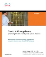
Always keep in mind that every NAC Appliance Server must have three distinct deployment modes defined before it will operate. Together, these three modes define how NAC Appliance Server interacts with hosts and the rest of the network. The first mode is Client/Server Adjacency. This mode defines whether NAC Appliance Server and the clients on the untrusted interface are on the same network or multiple Layer 3 hops from each other.
The second mode is Post–Client Certification mode. This mode defines whether client traffic continues to flow through NAC Appliance even after a client is certified. There are never any network changes with In-Band mode, so client traffic always flows through NAC Appliance. With Out-of-Band mode, a certified client is moved to a new VLAN that removes NAC Appliance from the traffic path. Network mode, the last of the three modes, determines whether NAC Appliance Server acts as a bridge (Virtual Gateway) or a router (Real IP Gateway) between its untrusted and trusted interfaces. Table 4-1 presents the distinct modes and their options. Every NAC Appliance Server must have one option from each mode type defined.
Table 4-1. Deployment Modes Required on NAC Appliance Servers
Note
It is possible to combine a mode option with any option from the other mode types. There are no restrictions on the combinations you can have across mode types. However, you can choose only one option within each mode type.
Note
In NAC Appliance, you will see a third network mode option called Real IP NAT Gateway. Due mostly to performance reasons, this mode is not supported for production use. Therefore, this book does not discuss Real IP NAT Gateway mode.
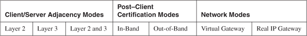
The flowchart in Figure 4-1 is designed to help you select the appropriate features for your environment. This chart gives you a general idea of the dependencies each mode of operation has and the order you should make your choices in. The detailed information needed to make informed choices as you navigate this flowchart will be covered in this section.
Figure 4-1. Design Selection Flowchart
How to Choose a Client/Server Adjacency Mode
A NAC Appliance solution can be deployed in two ways: central and edge. It is possible, even likely, that most environments will end up with a design that uses both types. Central deployment means that you will position your NAC Appliance Servers in the core or hub sites of your networks. For example, if you have several remote sites coming into a hub site, you would position NAC Appliance Server at the hub site and not at each remote site. Usually this means that NAC Appliance Server is Layer 3 adjacent to the clients it is controlling. Edge deployment is the opposite of central deployment; so, using edge, you position your NAC Appliance Server as close as possible to the clients it is controlling. For example, if you have several remote sites coming into a hub site, you would position NAC Appliance Server at every remote site. Usually this means that NAC Appliance Server is Layer 2 adjacent to the clients.
Note
The preceding terms central and edge are used to describe the logical placement of the NAC Appliance Servers. To avoid confusion, you should be aware that the terms central and edge can also be used to describe the physical deployment method of NAC Appliance Servers. That is not how the terms are used here.
As discussed, the chosen deployment type influences the adjacency mode used in the design. Keep in mind that like most other security technologies, the closer you can get to the clients you want to control, the more secure your design will be. However, the tradeoff for pushing security to the client edge is usually higher costs and scalability issues. If an environment has a pure client edge deployment, NAC Appliance Servers are always Layer 2 adjacent to all clients everywhere. This is highly secure and allows you the ultimate control over your clients. However, to accomplish this task might mean deploying 30, 50, or more NAC Appliance Servers. This many servers drives up the overall cost and increases the burden of configuration, management, and maintenance.
There are three choices for client/server adjacency:
- Layer 2 (L2) This is the default setting. All clients are expected to be Layer 2 adjacent to NAC Appliance Server's untrusted interface.
- Layer 3 (L3) When you enable L3 support, you also get L2 support. In this mode, NAC Appliance Server listens to all clients from any number of network hops away.
- Layer 2 Strict mode for Clean Access Agent This mode ensures that the clients are L2 adjacent to NAC Appliance Server. No network address translation (NAT) routers are allowed. This L2 enforcement requires the Clean Access Agent to be loaded on the client machine.
Layer 2 Mode
This mode is the default network setting for NAC Appliance Server. As such, it is the most commonly deployed as well. Layer 2 mode means that the clients are Layer 2 adjacent to the untrusted interface on NAC Appliance Server. In most LAN environments, L2 works just fine. If you have Layer 2 trunks between your access and distribution layer switches and your access switches do not use L3, you can usually use Layer 2 mode.
The most common reason to use Layer 2 mode in your environment is because of its ease of use. This is the most common and best understood deployment mode. It is the easiest to configure and troubleshoot. L2 mode adds the least amount of complexity to your network environment.
Layer 3 Mode
As mentioned, by enabling Layer 3 mode, you also get to use Layer 2 mode. Clean Access Agent always tries Layer 2 mode first and then tries Layer 3 mode. When NAC Appliance Server is in In-Band L3 mode, the client's MAC address is not needed because only the client's IP address is used to determine a host's identity. When NAC Appliance Server is in Out-of-Band L3 mode, the client's MAC address and IP address are used to determine a host's identity. For detailed information on Layer 3 mode's operations when used with Out-of-Band mode, see the section "Out-of-Band Mode."
Layer 3 In-Band mode is required if you use NAC Appliance to control clients coming in through a Cisco VPN on the concentrator, Adaptive Service Appliance, or Private Internet Exchange.
Here are some common reasons to use Layer 3 mode in your environment:
- Clients are coming in through a Cisco VPN.
- Access layer switches use L3 trunks to distribution switches.
- Cost of NAC Appliance Server at every remote office is prohibitive; instead, use a central NAC Appliance Server at headquarters.
- Protect sensitive network areas that are accessible only via a VPN, such as management and process control networks, by forcing clients to authenticate and certify before gaining entry.
- Need to authenticate and posture assess all clients accessing your network through third-party WAN connections. Common examples include business partners, vendors, and consultants that have direct routed connections into your network.
Layer 2 Strict Mode for Clean Access Agent
This mode was originally created for the universities that use NAC Appliance, but it is now being adopted by businesses as well. Many students were using wireless or wired NAT gateways in their dorm rooms. A NAT gateway causes NAC Appliance to authenticate and inspect only the first client and no subsequent clients. This is because the NAT device hides everyone behind a single IP and MAC address. This is also known as port address translation (PAT) or NAT overload. Therefore, regardless of how many clients are really behind the NAT gateway, NAC Appliance sees only a single MAC and IP pair. After this pair is certified, the gates are open to allowing subsequent—and potentially infected—hosts onto the network with no checking. Layer 2 Strict mode thwarts this problem by checking whether the client is behind a NAT or PAT device and denying the client access if it finds one.
Note
Layer 3 and Layer 2 Strict mode are mutually exclusive and cannot be used together.
L2 Strict mode can be used to combat the problem of users connecting rogue wireless access points or routers to the network. It is designed to sniff out the use of NAT gateways. Here is how it works:
1. Client's Clean Access Agent sends a login request to NAC Appliance Server. This request also sends the MAC addresses of all interfaces on the host.
2. NAC Appliance Server compares the MAC address in the packet header of the login request against the MAC addresses found inside the packet payload of the login request.
3. If there is no NAT gateway between the client and server, there will be a match of the MAC address in the header with one of those in the payload.
4. If there is a NAT gateway between the client and server, the match will fail and NAC Appliance will reject the login request. The reason the match fails is because the NAT gateway replaced the MAC in the packet header with a MAC of its own before sending it on to NAC Appliance. The user is forced to remove the NAT gateway to gain access to the network.
Here are some common reasons to use L2 Strict Mode for Clean Access Agent:
- Prevent the infection or compromise of your network through the use of multiuser NAT gateways.
- Prevent the spread and use of wireless NAT gateways. This is one way of stopping users from setting up their own wireless networks.
- If you charge for network access by the user, you can ensure that nobody sets up a wireless NAT gateway for freeloaders.
- Prevent NAT gateways from impeding the effectiveness of the network scanner.
Note
Layer 2 Strict mode requires the use of the Clean Access Agent. It does not currently support web login.
How to Choose a Network Mode
Cisco NAC Appliance supports two network modes: Virtual Gateway and Real IP Gateway. Network mode determines whether NAC Appliance Server bridges or routes traffic from its untrusted to trusted interfaces. Virtual Gateway is bridging, whereas Real IP Gateway is routing.
Virtual Gateway Mode
In Virtual Gateway mode, NAC Appliance acts like a Layer 2 transparent bridge or bump in the wire. This means it has no IP addresses on its interfaces and is essentially transparent to clients. It does, however, have one IP address for the management of NAC Appliance Server itself. In this mode, it acts much like a traditional Ethernet bridge does. Traffic is bridged as it flows from the untrusted to trusted side and vice versa. All the NAC Appliance security features will work in this mode. Virtual Gateway mode is the preferred method of deployment in most environments. This is because it does not require a re-architecture of the network and IP addressing.
For example, you have a Layer 2 802.1Q trunk between your access switch and your distribution switch. Your L3 distribution switch is configured to be the default router for clients on the access switch. You would like to have NAC Appliance posture assess the clients on the access switch. If you break the 802.1Q trunk by placing NAC Appliance Server between the two switches and use Virtual Gateway mode, you will not have to change anything on your clients' or network topology. The clients continue to use the same default gateway, and NAC Appliance is transparent to clients. If you use the same example but instead use Real IP Gateway mode on NAC Appliance Server, you will have to make changes. The default gateway of clients has to be changed to be NAC Appliance Server, not the distribution switch as before. In addition, a new subnet is needed for the trusted side of the NAC Appliance Server.
Here are some common reasons to use Virtual Gateway mode in your environment:
- Ease of use. It does not require a redesign of the network topology.
- No changes to subnets or client IP addresses are required.
- Routing protocols such as Enhanced Interior Gateway Routing Protocol (EIGRP) and Open Shortest Path First (OSPF) can flow through NAC Appliance uninhibited.
- Static routes are not required.
Real IP Gateway Mode
In Real IP Gateway mode, NAC Appliance Server acts just like a router. Traffic flowing from the untrusted side is routed to the trusted side. In this mode, NAC Appliance Server acts as the default gateway and, typically, as the DHCP server for clients on the untrusted networks.
Here are some common reasons to use Real IP Gateway mode in your environment:
- Guest or new network segments where you do not have a router already.
- You want NAC Appliance to be the DHCP server for your untrusted networks. The DHCP server embedded in NAC Appliance Server works only in Real IP Gateway mode. Given a Class C IP subnet, this feature can auto-generate /30 micro-subnets within that class C address space, allowing you to further segment your client traffic.
- You want NAC Appliance to be the default gateway for clients on the untrusted side.
In-Band Mode
In-Band has strengths and weaknesses. The purpose of this section is to bring those to light.
In-Band and Out-of-Band refer to the post client certification mode NAC Appliance Server is in. NAC Appliance Manager is used to centrally configure this mode on the servers. The first method to configure NAC Appliance is In-Band. In-Band means that NAC Appliance Server is always in the flow of traffic between the untrusted networks and trusted networks. This is regardless of whether or not the host on the untrusted side has passed assessment.
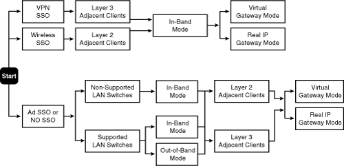
Figure 4-2 depicts an In-Band NAC Appliance Server design. As you can see, all traffic from the client machine must flow through NAC Appliance Server before it can leave the subnet.
Figure 4-2. In-Band Server Design
The Certification Process in In-Band Mode
This section will give an example of the Clean Access Agent certification process and the web login certification process. Certification, in the NAC Appliance world, is the process of user authentication and host security checks that a client must go through before it is allowed on the network. For a client to become certified, it must have properly authenticated with username and password and passed all the host security policies defined by the user's role. A host security policy is made up of all the checks and vulnerability scans configured for a given user role. A user's role is typically determined by some Active Directory or RADIUS attribute, such as group membership. Host security policies could include checking to make sure that antivirus definitions and Windows XP are up-to-date and using Network Scanner to check whether the machine is infected with a worm.
Certification Steps for Host with Clean Access Agent
These certification steps are based on the perspective of the host in Figure 4-2. The host has the Clean Access Agent installed.
Steps for Client to Acquire an IP Address
The steps for the client to acquire an IP address are as follows:
1. The host plugs into an Ethernet switch port. The switch port is a member of VLAN 100.
2. The host sends out a DHCP request to obtain an IP address.
3. NAC Appliance Server, also on VLAN 100, sees the DHCP request come into its untrusted network interface.
4. NAC Appliance Server, configured to be a DHCP server, replies to the host with a free IP address of 192.168.1.100/24 and a default gateway address of 192.168.1.1.
Clean Access Agent Authentication Steps
The Clean Access Agent authentication steps are as follows:
1. The host is now a member of the NAC Appliance Unauthenticated role. By default, hosts in this role will not be allowed to send any traffic, except DHCP and Domain Name System (DNS) queries, through their local NAC Appliance Server. You can modify the allowed traffic list as necessary for your environment.
2. Clean Access Agent, noticing the network connectivity, begins to send SWISS discovery packets to its default gateway. The SWISS discovery packets are sent first on UDP port 8905 (L2). If that fails, Clean Access Agent tries UDP 8906 (L3). Clean Access Agent is trying to locate a NAC Appliance Server in the network.
3. NAC Appliance Server, listening on the SWISS ports, hears the request and checks to see whether the host is already authenticated. Because it is not, NAC Appliance Server responds with the equivalent of an "I'm here; you need to log in" message.
4. NAC Appliance Server's reply message prompts the host's Clean Access Agent to pop up its login dialog box on the user's screen (see Chapter 3's Figure 3-2).
5. The user enters a username (Liam), password, and optionally an authentication provider, and then clicks Log In. An authentication provider defines the user database NAC Appliance will use to verify authentication. In this example, the local user database will be used.
6. Liam's login credentials are forwarded by NAC Appliance Server to NAC Appliance Manager for verification.
Clean Access Agent Host Security Posture Assessment Steps
The Clean Access Agent host security posture assessment steps are as follows:
1. After user authentication succeeds, NAC Appliance Manager moves to stage two: host security posture assessment. The user group that Liam is a member of determines his login role. The user's login role establishes what host security checks will be performed.
2. NAC Appliance Manager tells Clean Access Agent what security checks to perform on the host.
3. Clean Access Agent performs these checks and sends the results back to NAC Appliance Server, which forwards them to NAC Appliance Manager for certification.
4. If the host passes all Clean Access Agent security checks, skip Steps 5–7 and go to the "Clean Access Agent Network Scanner Steps" section.
5. For any failed checks, NAC Appliance Manager instructs NAC Appliance Server to tell Clean Access Agent to pop up a remediation dialog box on the user's screen. This dialog explains the issue found and gives details on how to repair it. See Figure 3-4 for a sample remediation dialog box.
6. NAC Appliance Manager then moves the user's role from Unauthenticated to Clean Access Temporary. This Temporary role is typically configured to allow the host access to only those networks or services from which it might need to obtain remediation patches or fixes.
7. The user then takes any necessary actions to fix the issues found. Failed checks are presented for remediation one at a time. If multiple failed checks occur, they must be repaired in the order presented. Skipping remediation of a failed check is an option only if the requirement was configured as optional.
Clean Access Agent Network Scanner Steps
The Clean Access Agent network scanner steps are as follows:
1. If no network scans are configured for the user's role, skip this section and go to the "Agent Post-Certification Steps" section.
2. If network scans (Nessus scans) are configured for the user's role, they are now performed. The host's local NAC Appliance Server is responsible for performing the network Nessus scans.
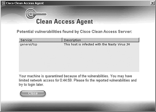
3. If any vulnerabilities are found on the host, Clean Access Agent displays them. This informs the user of the vulnerabilities found and alerts that user that he is in Quarantine mode. Figure 4-3 shows Clean Access Agent's vulnerability dialog box.
Figure 4-3. Clean Access Agent Scanning Vulnerability Dialog Box
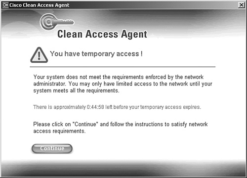
4. NAC Appliance Manager moves the user from the current role to the temporary role. The temporary role restricts the host's capability to talk freely on the network. Figure 4-4 shows Clean Access Agent's temporary access user notification dialog box.
Figure 4-4. Clean Access Agent Temporary Access User Notification Example
5. After all the vulnerabilities are patched, the user has to log out and log back in again to be rescanned.
6. The network vulnerability scan is performed again, but this time the client passes.
Agent Post-Certification Steps
The Clean Access Agent post-certification steps are as follows:
1. The host is now considered certified or "clean" and is put into its proper normal login role.
2. Optionally, the user is shown the acceptable use policy for the normal login role.
3. After the policy is accepted, NAC Appliance Manager adds the user and host to the certified devices list.
4. Any network bandwidth limits or network access lists configured for this normal login role take effect on the host traffic as it flows through NAC Appliance Server.
Login Steps for Host Using Web Login (No Clean Access Agent)
These login steps are based on the perspective of the host in Figure 4-2. The web login steps will be shown. This host does not have the Clean Access Agent installed.
Web Login Authentication Steps
The web login authentication steps are as follows:
1. The host plugs into an Ethernet switch port. The switch port is a member of VLAN 100.
2. The host sends out a DHCP request to obtain an IP address.
3. NAC Appliance Server, also on VLAN 100, sees the DHCP request come into its untrusted network interface.
4. NAC Appliance Server is configured to be a DHCP server, so it replies to the host with a free IP address of 192.168.1.100/24 and a default gateway address of 192.168.1.1.
5. At this point, NAC Appliance Manager checks to see whether the host is already authenticated. If not, the host is put into the Unauthenticated user role. Hosts in this role are not allowed to send any traffic, except DHCP and DNS queries, through their local NAC Appliance Server.
6. If the host is already authenticated, it is put back into its final normal user login role (for example, Employees).
7. NAC Appliance Server now waits for the user to open a web browser. It will drop any through traffic, except DHCP and DNS queries, sent from the unauthenticated host.
8. The user launches a web browser and requests a website. NAC Appliance Server intercepts the web page request.
9. The web page request triggers NAC Appliance Server to perform certification of the host. The original web page request is replaced with a redirect to NAC Appliance Server's web login page. This starts the authentication process, the first step toward becoming certified.
10. The user's web browser is redirected to the NAC Appliance web login page. The user must enter a username and password. NAC Appliance Server forwards the user's login credentials to NAC Appliance Manager for verification. See Figure 3-3 for a sample web login page.
Web Login Network Scanning Steps
The web login network scanning steps are as follows:
1. After user authentication succeeds, NAC Appliance Manager moves to stage two: network scanning. The user group that the user is a member of determines the login role he is in.
2. The web login process also sends the host's operating system type to NAC Appliance. The host's operating system type and user role are used to decide which Nessus plug-ins will be used for the network scan.
3. NAC Appliance Manager instructs NAC Appliance Server which Nessus plug-ins to use for the network scan.
4. After performing the network scan, NAC Appliance Server sends the results to NAC Appliance Manager. Each plug-in will return no value if nothing was found, or will result in a security hole, warning, or info alert.
5. NAC Appliance Manager then matches the plug-in alert results (hole, warning, or info) against the alert results considered necessary for the specific plug-in to be considered a vulnerability. For example, plug-in XYZ is a vulnerability if the alert result is a security hole. This criterion is specific to the host's role and operating system.
6. Any matches result in the host being put into a quarantine role or blocked from the network completely.
7. If set to block network access, the user is shown the blocked access web page. No further steps are performed. This is a rather harsh way to treat users and is not frequently used.
8. If set to quarantine, the user is shown a user agreement page that must be acknowledged in order to complete the login.
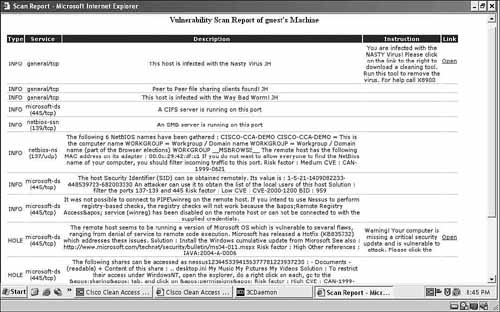
9. Typically, the network vulnerability scan report web page is opened for the user. This report contains a description of the vulnerabilities found, and instructions and URL links to facilitate patching them. See Figure 4-5 for a scan report example.
Figure 4-5. Sample Vulnerability Scan Report
10. Hosts in the quarantine role have a configurable amount of time to patch or fix themselves. After the session timer runs out, the host is automatically logged out.
11. After the user patches all the vulnerabilities, that user has to be rescanned. The expiration of a relogin or session timer triggers a new network scan.
12. The network vulnerability scan is performed again, but this time the host passes.
Post–Web Login Steps
The post–web login steps are as follows:
1. The host is now considered clean and is put into its proper normal login role.
2. Optionally, the user is shown the user agreement page for the normal login role.
3. After the agreement page is accepted, NAC Appliance Manager adds the user and host to the online user list.
4. Any bandwidth limits or network access lists configured for the normal login role take effect on traffic as it flows through NAC Appliance Server.
Advantages of Using In-Band Mode
When designing any security solution, it is important to understand the advantages and disadvantages of the various product features and modes of operation. There are several compelling reasons to use In-Band instead of Out-of-Band mode. The following is a list of the major advantages In-Band has to offer:
- It is the easiest mode to design, configure, deploy, and troubleshoot.
- It is less intrusive in environments with IP phones.
- It is the only mode that allows you to use bandwidth rate-limiting and traffic control (access lists) on certified clients.
- It allows for the use of the heartbeat timer to automatically log off users who have been inactive for a set time.
- It is required for VPN and wireless clients.
- In-Band mode works regardless of the type of Ethernet switches in your network.
- In-Band mode works even if your hosts are connected to Ethernet switches that you do not control, such as switches controlled by another department or another company.
Disadvantages of Using In-Band Mode
In-Band mode has a few disadvantages when compared to Out-of-Band mode. You should check these disadvantages against your security policy and network environment requirements for relevancy. The following is a list of the major disadvantages of using In-Band mode:
- In-Band does not provide true switch port–level host control. In certain situations, it is possible for an unauthenticated host to talk to other hosts in the same Layer 2 domain (VLAN) without first passing NAC Appliance assessment.
- Because the traffic from hosts always flows through NAC Appliance in this mode, the server is another possible point of failure in the network. If the server dies in In-Band mode, all host traffic stops flowing. Using NAC Appliance Server high availability and failover decreases the risk of that occurring.
- A NAC Appliance Server in In-Band mode that loses communication with its NAC Appliance Manager could affect traffic. If set to fail closed, existing certified hosts will not be affected but any new hosts will be denied access. If set to Fallback mode, NAC Appliance Server will fail open, allowing all traffic to flow through unchecked.
- In-Band mode could adversely affect the performance of your network. Each server has a maximum throughput of approximately 950 Mbps. If your network infrastructure (uplinks) is faster than 950 Mbps, NAC Appliance could theoretically be a bottleneck.
- In-Band mode, unlike Out-of-Band mode, does not give you the ability to set which switch ports you want to be posture assessed and which you do not. It can only posture assesses whole subnets or VLANs. MAC address exceptions must be made for those hosts in a VLAN that you do not want to posture assess.
- If you use In-Band in Real IP Gateway Layer 3 adjacency mode, NAC Appliance will not support any routing protocols and relies solely on static routing. If you put NAC Appliance in the middle of a routed topology, it will break any routing protocols trying to flow through NAC Appliance Server. When designing for this mode, think of NAC Appliance Server as a router that supports only static routing.
Where You Can Use In-Band Mode
In-Band mode is by far the most flexible deployment mode available. It can be used almost anywhere. It is the only mode that can be used behind VPN and wireless networks. And, of course, it can be used in a LAN. It is great for protecting guest networks and conference rooms. These areas can really take advantage of In-Band mode's always-available bandwidth rate limiting, session timeout, and traffic control (access control list or ACL) features. There are currently no known areas of a network where In-Band mode does not work.
Out-of-Band Mode
Out-of-Band mode was created to fill some of the perceived gaps of In-Band mode operating in a LAN environment. OOB is designed for one purpose: to control hosts that connect directly to Cisco LAN switches. It is not capable of operating in wireless or VPN environments or those with non-Cisco switches. Businesses wanted true switch port–level network admission control, and they did not want the appliance to be a bottleneck on their high speed LANs.
To accomplish this, OOB uses switch port–level VLANs—two VLAN types, in fact. The first type is the authentication VLAN, and the second type is the access VLAN. While clients are in the authentication VLAN, all their traffic passes through NAC Appliance just as in In-Band mode. However, after the client is authenticated and certified, it is moved into the access VLAN where all the client traffic bypasses NAC Appliance completely. The effect of this behavior is that NAC Appliance is In-Band with the client traffic only during the process of authentication, certification, and remediation. After that process completes, client traffic no longer flows through NAC Appliance.
OOB works by changing the VLAN of the host's switch port. OOB mode provides the ability to communicate with and reconfigure Cisco Catalyst switches real-time via Simple Network Management Protocol (SNMP). It is the job of NAC Appliance Manager to reconfigure switch ports using SNMP write commands. For this to work, NAC Appliance must be told when and where new hosts connect to the network. This is accomplished by configuring the LAN switches to send SNMP traps when new hosts connect to the network.
Tip
SNMP is critical to the operation of Out-of-Band mode. When using Layer 3 Out-of-Band to control clients across WAN links (for example, remote site clients controlled by a central NAC Appliance Server), it is highly recommended that priority quality of service (QoS) for SNMP traffic be configured on the relevant WAN routers.
When a new host connects to a switch port, NAC Appliance is notified using one of the following trap types:
- MAC-Notification Trap This type of SNMP trap is triggered and sent anytime a new MAC address is detected on a switch port. It includes the MAC address and port number of the new host. This trap triggers even if there are multiple clients or a hub on a single switch port. This is the preferred notification method, but it is not supported by all Cisco switches. See the "Switches Supported by NAC Appliance Out-of-Band" section in this chapter for details. Example 4-1 shows a MAC-notification trap message.
Example 4-1. MAC Notification Message
Internet Protocol, Src: 192.168.1.250 (192.168.1.250), Dst: 192.168.3.20
(192.168.3.20)
User Datagram Protocol, Src Port: 51493 (51493), Dst Port: snmptrap (162)
Simple Network Management Protocol
Version: 1 (0)
Community: public
PDU type: TRAP-V1 (4)
Enterprise: 1.3.6.1.4.1.9.9.215.2 (SNMPv2-SMI::enterprises.9.9.215.2)
Agent address: 192.168.1.250 (192.168.1.250)
Trap type: ENTERPRISE SPECIFIC (6)
Object identifier 1: 1.3.6.1.4.1.9.9.215.1.1.8.1.2.0 (SNMPv2-
SMI::enterprises.9.9.215.1.1.8.1.2.0)
Value: Hex-STRING: 01 00 C8 00 0C 29 42 DF C1 00 08 00
This captured SNMP MAC-Notification trap message shows the client's MAC address as 000C-2942-DFC1.
- SNMP Linkup Trap This trap is triggered and sent anytime a switch port changes its state to operational. This occurs only when a port goes from not being used (disconnected) to being used (connected). Because of this, only the first client on a port is ever detected. This trap includes the port number but does not include the MAC address of the client. To obtain the vital client MAC address, NAC Appliance Manager issues an SNMP query or get request to the switch. The query looks up the MAC address for the port sent by the linkup trap. It is because of the extra query that linkup traps are not the preferred method. Example 4-2 shows a linkup trap.
Example 4-2. Linkup Trap
Internet Protocol, Src: 192.168.1.250 (192.168.1.250), Dst: 192.168.3.10
(192.168.3.10)
User Datagram Protocol, Src Port: 52464 (52464), Dst Port: snmptrap (162)
Simple Network Management Protocol
Version: 3 (3)
PDU type: TRAP-V2 (7)
Object identifier 2: 1.3.6.1.6.3.1.1.4.1.0 (SNMPv2-MIB::snmpTrapOID.0)
Value: OID: IF-MIB::linkUp
Object identifier 3: 1.3.6.1.2.1.2.2.1.1.10006 (IF-MIB::ifIndex.10006)
Value: INTEGER: 10006
Object identifier 4: 1.3.6.1.2.1.2.2.1.2.10006 (IF-MIB::ifDescr.10006)
Value: STRING: FastEthernet1/0/6
Object identifier 6: 1.3.6.1.4.1.9.2.2.1.1.20.10006 (SNMPv2-
SMI::enterprises.9.2.2.1.1.20.10006)
Value: STRING: "up"
When a host disconnects, the switch sends a linkdown SNMP trap message to NAC Appliance. The linkdown trap message includes the switch port number that disconnected. Example 4-3 shows a captured linkdown SNMP trap message.
Example 4-3. Linkdown SNMP Trap Message
Internet Protocol, Src: 192.168.1.250 (192.168.1.250), Dst: 192.168.3.20
(192.168.3.20)
User Datagram Protocol, Src Port: 51493 (51493), Dst Port: snmptrap (162)
Simple Network Management Protocol
Version: 1 (0)
Community: public
PDU type: TRAP-V1 (4)
Agent address: 192.168.1.250 (192.168.1.250)
Trap type: LINK DOWN (2)
Object identifier 1: 1.3.6.1.2.1.2.2.1.1.10006 (IF-MIB::ifIndex.10006)
Value: INTEGER: 10006
Object identifier 2: 1.3.6.1.2.1.2.2.1.2.10006 (IF-MIB::ifDescr.10006)
Value: STRING: FastEthernet1/0/6
Object identifier 4: 1.3.6.1.4.1.9.2.2.1.1.20.10006 (SNMPv2-
SMI::enterprises.9.2.2.1.1.20.10006)
Value: STRING: "down"
Notice that the trap message has the interface number as well as the "down" message. This is all the information NAC Appliance needs to reset the switch port's security policy.
The big advantage of OOB is that hosts are within the control of NAC Appliance only during authentication, assessment, and remediation. After the host is authenticated and certified, its switch port moves to the access VLAN, which is external to NAC Appliance. At this point, the host never interacts with NAC Appliance again until it logs out or disconnects from the network.
All OOB designs have the following two VLAN types:
- Authentication (Auth) VLAN When a host first connects to the switch, this is the VLAN type it is placed into. While in an authentication VLAN, the host is always In-Band with NAC Appliance Server. All client traffic is forced to pass through NAC Appliance Server. Client authentication, posture assessment, and remediation are performed in this VLAN.
- Access VLAN After a host completes authentication and certification, it moves into the access VLAN type. A client in this VLAN never interacts with NAC Appliance and is considered Out-of-Band. While on the access VLAN, no client traffic flows through NAC Appliance Server.
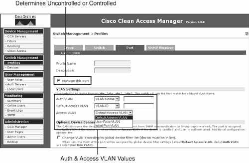
NAC Appliance uses port profiles to define the VLAN name or number these VLAN types are set to. The host's switch port location is used to determine which port profile to use. For example, a port profile for switch IDF2 port 3/1 assigns VLAN 30 for authentication and VLAN 100 for access. A port profile is used to determine whether a particular switch port is controlled or uncontrolled by NAC Appliance. If a port is controlled, the port profile will define what authentication and access VLANs should be used, as well as other port behavior. The following are the four types of port profiles for switch ports:
- Unmanaged/Uncontrolled Ports of this type will not be controlled by NAC Appliance. Common uses of this type include any nonclient switch ports, such as printers, servers, and other network devices.
- Managed/Controlled Port with Auth VLAN and Default Access VLAN This managed port profile type defines the auth VLAN and the access VLAN explicitly and statically. If a port is a member of a profile of this type, both the auth and access VLANs will be the same for all other ports in this profile. This is regardless of their user role, location, or any other criteria.
- Managed/Controlled Port with Auth VLAN and Switch Initial VLAN This type statically defines the auth VLAN but not the access VLAN. The access VLAN value is always set to whatever the switch port VLAN was before the user moved to the auth VLAN. The initial VLAN value is learned and stored by NAC Appliance Manager during the initial discovery of the LAN switch. If necessary, the original initial VLAN can be changed or updated later in NAC Appliance Manager.
- Managed/Controlled Port with Auth VLAN and User Role VLAN The auth VLAN is statically configured for this type, but the access VLAN changes depending on the user's ultimate role. The access VLAN is defined in the user's role. The access VLAN will, therefore, change depending on who authenticates and what user role they are put into. Each user role has a field that defines that role's access VLAN name or number.
Figure 4-6 shows the port profile configuration screen.
Figure 4-6. Port Profile Configuration Screen
How the Adjacency Mode Affects Out-of-Band Operation
Out-of-Band mode supports both Layer 2 and Layer 3 Adjacency modes on the NAC Appliance Server. The adjacency mode you choose will change the flow of operations for OOB.
In Layer 2 OOB mode, all clients in the authentication VLAN are Layer 2 adjacent to NAC Appliance Server. This means that NAC Appliance Server is in the same IP subnet as the clients and is able to see the real MAC address of all its clients. As described earlier, after certification finishes and the client moves to its access VLAN, NAC Appliance Server is no longer in-band. If possible, using Layer 2 OOB instead of L3 OOB is recommended. Layer 2 OOB mode is much easier to design, configure, deploy, and support.
In Layer 3 OOB mode, all clients are one or more routed L3 hops away from the NAC Appliance Server. This means that for the client to reach the NAC Appliance Server, it must pass through one or more routers. Layer 3 mode also supports Layer 2 adjacent clients, so when you turn on Layer 3 mode, you also get Layer 2 mode as well. L3 OOB was designed for customers with routed links to their campus access layer switches.
Traditionally, the link between access and distribution switches was an 802.1q or Inter-Switch Link Layer 2 trunk. It is becoming increasing popular to enable L3 routing on uplink trunks between the access and distribution layer switches. This means that there is an L3 hop between clients and NAC Appliance Server. The most common use case for L3 OOB is campus networks with routed uplinks to the access layer. You can also use L3 OOB to centralize the NAC Appliance Servers at your network core or hub site, and use those NAC Appliance Servers to control hosts at WAN remote sites.
The biggest benefit of using L3 OOB for remote site NAC is that it allows you to centralize your NAC Appliance Servers at the core and saves you the expense of having NAC Appliance Server at every WAN remote site. Nevertheless, you must weight this benefit against the added complexities and issues that using L3 OOB for remote site NAC creates. Typically, you will find that positioning either an L2 In-Band or L2 OOB mode NAC Appliance Server at every WAN remote site is the best solution. If L3 OOB turns out to be the best solution for your environment, you must consider the following to ensure a successful design:
- Will Clean Access Agent be deployed using the WAN? If so, allow for an approximately 8 MB initial per client full download and approximately 4 MB for subsequent client updates thereafter.
- Consider using a file-caching technology at each client remote site to optimize WAN bandwidth utilization.
- Is the Network Scanning engine being used across the WAN? If so, how much bandwidth will it use per client?
- If you choose policy-based routing (PBR), are all the WAN routers and every L3 device between the client switch and the central NAC Appliance Server capable of running PBR? What performance hit will your router model take when PBR is enabled? Do you have the rights or control necessary to ensure that PBR is enabled on these L3 devices?
- How much additional traffic will be created over the WAN for remediation downloads, authentication, SNMP traffic, and other auth VLAN–type activities?
- QoS should be configured on all WAN routers to prioritize SNMP traffic from NAC switches. SNMP traffic is critical to the operation of NAC Appliance and must be given priority over the WAN.
- Consider using QoS in WAN routers to prefer access VLAN traffic over authentication VLAN traffic. This will ensure that business-critical traffic is not affected by spikes in client-remediation traffic.
- The first few weeks of NAC Appliance deployment will create a large spike in WAN traffic as clients download required patches and updates. Make sure that your WAN can accommodate the traffic loads during this initial deployment stage. Consider using the bandwidth control feature of NAC Appliance to help with this.
- Each time a new security check or requirement is enforced, you will see a temporary spike in WAN traffic as clients download the files necessary to pass the new check. Consider how often you anticipate these updates to occur and the WAN bandwidth necessary during these times.
The following are some common reasons to use Layer 3 Out-of-Band mode:
- L3 OOB is for wired LAN deployments only. Wireless and VPN deployments are not currently supported.
- L3 OOB is best used in routed access or campus deployments where port-level NAC is desired.
- L3 OOB can also be used for remote WAN sites, but other deployment types should be considered as well.
- L3 OOB should be used in environments that use Layer 3 switch trunks instead of L2 trunks.
- In most cases, using Layer 3 Out-of-Band mode results in having to deploy fewer NAC Appliance Servers throughout your network.
Because the client is not Layer 2 adjacent, NAC Appliance Server cannot view the real MAC address of its clients. Due to normal network behavior, each router along the path replaces the MAC address of the client's packets with its own MAC Address before forwarding them. This causes a problem for NAC Appliance. NAC Appliance needs the MAC address of the client in order to match it with a switch's MAC notification message. This matching process is how the NAC Appliance determines which switch port a particular client is connected to. The following are two ways for NAC Appliance to learn the client's real MAC address:
- Using the Clean Access Agent v4.0 or greater.
— Clean Access Agent sends the client's MAC address to NAC Appliance.
— Clean Access Agent is the preferred method for detecting the client MAC address when using L3 OOB mode.
- Using the ActiveX or Java applet with web login.
— The web login page downloads the ActiveX control or Java applet. The control or applet then discovers and sends the MAC address of the client to the NAC Appliance.
— The control or applet is downloaded only to detect the client MAC address when Clean Access Agent cannot detect the MAC address.
— For Internet Explorer browsers, the ActiveX control is preferred and faster than the Java applet.
The following is an example of the MAC address discovery process in L3 OOB mode:
1. Host A connects to switch A.
2. Switch A sends MAC-notification and linkup SNMP traps to NAC Appliance. The MAC-notification trap includes the MAC address of the host and the switch port it is located on.
3. NAC Appliance Manager records and stores these traps.
4. Clean Access Agent sends the client's MAC address, along with a login request, to NAC Appliance.
5. NAC Appliance Manager then performs a lookup to match the MAC address from Clean Access Agent with a MAC address it received via a switch MAC-notification trap. When it finds a match, it knows exactly what switch and port the Clean Access Agent login request is originating from.
6. NAC Appliance Manager now has a complete IP-MAC-port mapping.
After the location is known, NAC Appliance Manager then looks up the port profile for the switch port and goes from there.
Layer 3 Out-of-Band Traffic Control Methods
Another important design requirement of using Layer 3 Out-of-Band is traffic control. While in the authentication VLAN, no client traffic should be allowed to roam freely throughout the network: It must be controlled. Because NAC Appliance Server is not Layer 2 adjacent to the client, the client's traffic is not forced through NAC Appliance Server. If you do not implement controls on the authentication VLAN traffic, it can route to anywhere the local default router allows it to go. Of course, this defeats the purpose of NAC, which is controlling clients until they are authenticated and certified. The following are the methods you can use to control the traffic of clients in the authentication VLAN:
- Policy-based routing
- Access control lists
- VPN routing and forwarding (VRF)
- Virtual private networks
The recommended methods are PBR and ACLs. PBR and ACL methods will be discussed in detail, but first a brief overview of the VRF and VPN methods is necessary. VRF and VPN are tunneling technologies that you can use to tunnel the client auth VLAN traffic back to a central NAC Appliance Server. VRF and VPN are typically used for WAN remote sites configured for L3 OOB. To properly capture the client traffic, you would configure a tunnel with one endpoint being the remote site's auth VLAN router and the other endpoint being the central NAC Appliance Server's untrusted network router. This tunnel ensures that all auth VLAN client traffic is forced to flow through the central NAC Appliance for authentication, certification, and remediation. You might consider these technologies for your design if you are already using them on your WAN and you own or manage the tunnel endpoint routers. VPN and VRF design is out of the scope of this book.
When deciding which traffic control method to use, PBR and ACLs should be at the top of your list. It is also likely that you will end up using both in some environments. Policy-based routing works by forcing defined traffic to follow a set path through the network. In this case, you would define the auth VLAN traffic and force it to always go through a central NAC Appliance Server. PBR overrides the normal routing path traffic would normally take with its own predetermined path that leads to NAC Appliance Server. This requires that a PBR policy be configured in every L3 device along the set path.
ACLs work by filtering traffic based on a set of rules, just like a firewall. In this case, you would configure inbound ACLs on each remote site router. You want to use the router or L3 switch interface that is closest to the clients you are going to filter. The closest L3 device to auth VLAN clients would be the default router for the auth VLAN. Given that each remote site will typically have only one authentication VLAN, the ACL method can scale fairly well in a large remote site topology. It works out to a 1:1 ratio; you have to configure one router ACL for each remote site being protected with NAC. For large networks, the ACL method will be easier to deploy than the PBR method. This is mainly because with the PBR method, you still have the 1:1 ratio of one PBR policy on every remote site router. In addition, you will have to add or modify the PBR policy of each router in the path from the remote client to the central NAC Appliance Server.
The ACLs you configure on the remote site routers allow only the traffic types that you determine clients need while they are in the authentication VLAN. Remember the auth VLAN is used for authentication, certification, and remediation. So, your allowed traffic would typically include access to NAC Appliance Server, remediation servers, DNS, limited ping, and AD demilitarized zone servers if AD SSO is being used.
When using the ACL method, client traffic is not forced to go through NAC Appliance Server at any time. This is why web login does not automatically redirect users with only the ACL method. A workaround for guest users is to print out for them the URL address for web login. They can then put that in their browser to gain access to web login. Clean Access Agent works just fine because it is preconfigured with the IP address of NAC Appliance Server or a device behind NAC Appliance Server. This allows Clean Access Agent to discover, communicate with, and receive instructions from NAC Appliance Server. Table 4-2 shows the strengths of PBR and ACL traffic control methods.
Table 4-2. PBR and ACL Traffic Control
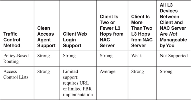
Policy-based routing makes an excellent control method for routed campus networks and WAN remote sites with only one or two hops between the clients and the NAC Appliance Server. Remember that the more L3 hops there are between clients and the NAC Appliance Server, the greater the number of devices you have to configure for PBR. This is why PBR becomes a less and less attractive option as the hop number increases. Another strong benefit PBR has is its support for both Clean Access Agents and web login, or Clean Access Agent–less, clients. Web login requires that auth VLAN web traffic must flow through NAC Appliance Server. Because PBR does exactly that, it can support web login.
A routed campus network typically has tens or hundreds of L2 access switches collapsing via L3 uplinks to the distribution layer. In that campus topology, you would position NAC Appliance Server in the distribution layer. The topology gives you a natural PBR traffic choke point: the distribution routers or L3 switches. All auth VLAN traffic coming from the access switches passes through the distribution switches. By configuring policy route statements at the distribution layer, you can force any traffic coming from the access switches' auth VLAN to go to NAC Appliance Server's untrusted IP address or interface number. Using PBR in this way allows you to control the auth VLAN client traffic with minimal effort and complexity. PBR typically doesn't work well for WAN remote sites.
The ACL method works well for remote sites. This is especially true when the remote clients are several L3 hops away from the central NAC Appliance Server. The ACL method is the preferred method if the L3 devices in your network don't support PBR or all are not managed by you. This method is popular in environments where the ISP owns the routers at each remote site or where the remote site device is a firewall not capable of running PBR.
The biggest disadvantage of using ACLs is that doing so requires the use of Clean Access Agent and provides limited support for web login. As stated previously, this is because in order for web login to work, client web traffic must be forced to flow through the central NAC Appliance Server. The ACL method, by itself, has no way of forcing traffic to follow a set path through to NAC Appliance Server. Not being able to support the web login service is a big problem. The web login service will be needed in most environments because rarely will Clean Access Agent be supported by and deployed to everyone's PC at all times. In addition, it is a common practice to use the web login service to distribute clean access agents to new users. The following are some of your options for using the ACL method but still supporting web login:
- Distribute an authentication URL to Clean Access Agent–less users that points to or goes through NAC Appliance Server. This causes the redirect to happen and the login page to display.
- Implement a limited deployment of PBR.
The first option is straightforward. When new users arrive at your site, they are given a username and password in addition to the URL they must go to for authentication. If NAC Appliance Server were running in Real IP Gateway mode, the URL could point to either NAC Appliance Server's trusted interface or a web server reachable only by going through NAC Appliance. It might look something like this: http://guest.companyxyz.com. Your DNS would resolve this to the IP address of the trusted interface of the NAC Appliance Server or the web server.
Tip
If you use the trusted interface of your NAC Appliance Server as the destination for your authentication URL, be sure to send users to a prespecified web page after they successfully log in. By default, NAC Appliance sends the user to the previously or originally requested URL. If left unchanged, that URL will point to the trusted interface of NAC Appliance and will result in the user receiving a 404 page not found error in the web browser. This would not be pleasant for the user. To change the URL, edit the user role page. Specify a specific URL, such as a company welcome page, in the appropriate field next to the option After Successful Login Redirect To.
A user going to that page is redirected to the web login page. Normal web login procedures would then be followed. If NAC Appliance Server were in Virtual Gateway mode, you would hand out a URL of a web server that was on the trusted side of NAC Appliance Server. This web server must be reachable only by going through NAC Appliance Server. When the user attempts to go to this web server, NAC Appliance Server redirects him to the web login page. Handing out URLs is not the most efficient method and could result in additional help desk calls from those users who were not given a URL to use. However, it is the simplest and easiest method by far and should work efficiently in environments that require guests to sign in at a front desk. The front desk personnel could be assigned the task of handing out the necessary information. Figure 4-7 shows a workflow example of how this could work.
Figure 4-7. ACL Traffic Control Method Using Authentication URL
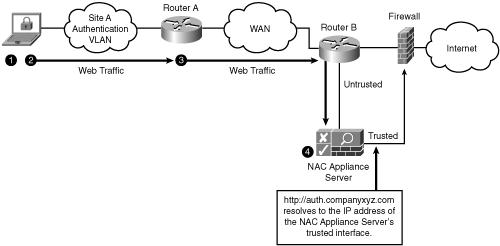
The following is an explanation of the steps presented in Figure 4-7:
1. On arriving, a user receives a username and password. He is told that to gain access to the network, he has to go to a website and enter his credentials. This website would be your authentication URL.
2. The user opens a web browser and enters the authentication URL, such as http://auth.companyxyz.com. The HTTP connection heads toward the web server.
3. Web traffic to the auth URL is permitted by router A's ACL. For example:
Permit any traffic to remediation resources
Permit any web traffic to auth URL site (that is, NAC Server)
4. NAC Appliance Server redirects the user to the web login page.
The second option is implementing a limited deployment of policy-based routing. This option does not rely on the user having prior knowledge of how to access the system—it works automatically. This implementation of PBR is limited to forcing web traffic through to only the central NAC Appliance Server. This is accomplished by implementing PBR on only the routers that sit in front of your company's Internet connection. The untrusted interface of NAC Appliance Server should be Layer 2 adjacent to an interface on an Internet-facing router. The PBR policy forces TCP port 80 and 443 traffic coming from any remote site auth VLAN to go through the NAC Appliance Server. Any auth VLAN user who opens a web browser and attempts to contact an Internet website is forced by the PBR policy to go through the NAC Appliance Server. NAC Appliance Server then issues a redirect to the web login page. Normal web login operation takes over from there. For this to work and be secure, you must do the following:
- Add ACL statements to every remote site auth VLAN router that denies traffic from the auth VLAN to any internal host and permits any other TCP port 80 and port 443 traffic. This permitted traffic is Internet bound and is caught by the PBR policy. These ACL additions are typically added at the bottom of the existing ACL. This allows the permits for remediation servers, AD, and so on to continue to function.
- The PBR policy must include the IP subnets for all remote site auth VLANs. If a remote site auth VLAN is missed, those clients will have full unrestricted Internet access.
Tip
A best practice is to use IP address ranges for all remote site auth VLANs that could be easily super-netted in the PBR policy. For example, always use the 10.10.X.0/24 address space when carving out subnets for remote site auth VLANs. This allows you to super-net them to 10.10.0.0/16 in a PBR policy.
Figure 4-8 gives a flow example when using ACLs for L3 OOB traffic control.
Figure 4-8. L3 OOB Traffic Control Using ACLs and Web Login
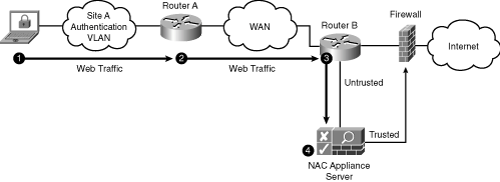
The following is an explanation of the steps presented in Figure 4-8:
1. The user opens a web browser and enters an external URL, such as http://www.google.com. The HTTP connection heads toward the Internet.
2. Web traffic to the Internet is permitted by router A's ACL. For example:
Permit any traffic to remediation resources
Deny any traffic to internal hosts
Permit any web traffic to anywhere (for example, the Internet)
3. The PBR on router B (Internet router) forwards web traffic sourced from site A auth VLAN to NAC Appliance Server.
4. NAC Appliance Server redirects the user to the web login page.
Policy-based routing is a Cisco IOS router feature. PBR can be used to force all authentication VLAN traffic to follow a predetermined path through the network. PBR allows you to route traffic based on its source IP address, or other criteria, rather than just its destination IP address as is typical of routing. This path will of course take the traffic to NAC Appliance Server. It is not possible for traffic to deviate from this predetermined path. For simplicity's sake, you can think of PBR as a tunnel through the network that traffic from the authentication VLAN is forced to go through. At the end of the tunnel is the untrusted interface of NAC Appliance Server. This accomplishes the goal of making sure that all traffic of hosts still on the authentication VLAN is forced to pass through NAC Appliance Server. See Figure 4-9 for a look at policy-based routing.
Figure 4-9. Policy-Based Routing Overview
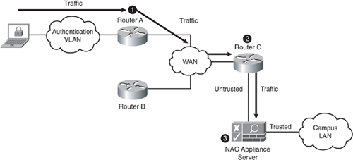
The following is a breakdown of the numbered process shown in Figure 4-9:
- PBR policy on router A: All traffic coming from the authentication VLAN is forwarded to router C.
- PBR policy on router C: All traffic coming from the authentication VLAN is forwarded to NAC Appliance Server.
- NAC Appliance Server performs authentication, certification, and remediation. It also controls what traffic can flow through to the trusted side.
Note
After a client moves to its access VLAN, PBR, ACL, VPN, and VRF policies no longer affect its network traffic.
How the Network Mode Affects Out-of-Band Operation
Out-of-Band mode supports both Virtual Gateway and Real IP Gateway network modes on NAC Appliance Server. Given that OOB mode relies on VLANs for segmentation of clients, you need to be aware of the process NAC Appliance goes through to change a client's IP address as it transitions from the authentication VLAN to the access VLAN. If you choose to use Real IP Gateway mode, you are required to have different IP subnets for the authentication VLAN and the access VLAN. This is because NAC Appliance is routing between the VLANs, and routers can't route traffic between two identical IP subnets. If you choose Virtual Gateway mode, you have the flexibility of having the auth VLAN and access VLAN be the same or different IP subnets. This is because NAC Appliance is bridging and uses VLAN remapping.
If you choose to have separate subnets for the auth and access VLANs, you need to consider how you can force the client to change its IP address at the appropriate times. The issue revolves around the difficulty in forcing a client to change its IP address. After a client receives an IP address from a DHCP server, it doesn't like to relinquish that IP address for a new one. In fact, a number of operating systems—some Linux variants, for example—require you to reboot if you change IP addresses. To deal with the IP address change problem, NAC Appliance uses switch port bouncing and DHCP Release/Renew. Bouncing a port simply means disconnecting and reconnecting it. This port reset action forces the client's operating system to clear its existing IP address and request a new one. The problem is that this method does not work with all operating systems, Linux being one example.
The second way NAC Appliance can force a client to change its IP address is using DHCP release/renew functionality. The way this works is that Clean Access Agent or the web login applet sends a DHCP release/renew instruction to the host's operating system. This is the equivalent of typing ipconfig /release followed by ipconfig /renew in a Windows command prompt. The problem with this method is that only Windows operating systems are unconditionally supported as of this writing. Macintosh systems support release/renew only when using the web login applet; the Clean Access Agent release/renew is not supported as of this writing.
Caution
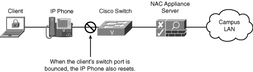
In IP telephony environments, port bouncing must be avoided and is not an acceptable method. You must either preserve the client's IP address as it moves from the authentication VLAN to the access VLAN or use the DHCP release/renew method. Because of the port bounce, IP phones on those client ports will also be reset. This is because the client is plugged into the IP phone and the phone is then plugged into the switch. See Figure 4-10 for an example of this arrangement.
Figure 4-10. Client with an IP Phone
If the host's IP address needs to be changed, the DHCP release/renew method is recommended. However, if port bouncing is enabled, its physical Ethernet switch port is bounced by NAC Appliance. Port bouncing is an option because it forces the operating system of the host to release the old IP address and request a new one. One of the undesirable effects of port bouncing is that if the host is connected to an IP phone, the IP phone is also bounced.
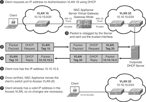
It is recommended that Virtual Gateway mode be used in any IP telephony environment in which hosts are plugged into IP phones. Only Virtual Gateway mode can be configured to never change the IP address of the host and therefore mitigates the need for port bouncing or DHCP release/renew. This in turn reduces the complexity of the design. Virtual Gateway (transparent bridging) mode can be configured so that the IP address the client receives in the authentication VLAN is also valid in the access VLAN. NAC Appliance will not bounce the switch port because the IP address never changes. Because the switch port never bounces, the IP phone is not affected in any way. The downside to using this method is that you cannot use role-based VLAN assignment. Everyone must be assigned to the same access VLAN. See Figure 4-11 for a look at how IP addressing is typically handled with OOB in Virtual Gateway mode.
Figure 4-11. IP Addressing with OOB in Virtual Gateway Mode
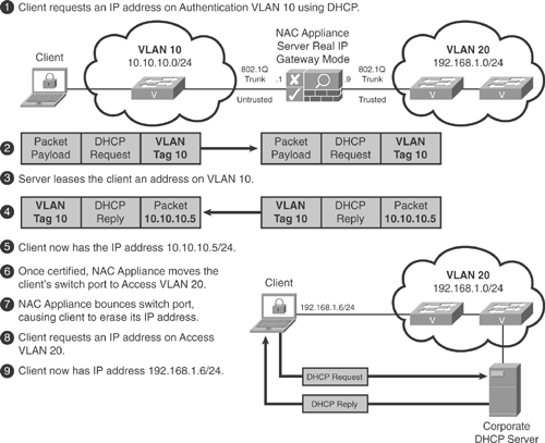
In Real IP Gateway (Routing) mode, the client's IP address is always changed when it transitions between the authentication and access VLANs. To force this change on the client, the switch port must be bounced or DHCP release/renew must happen. Typically, NAC Appliance Server acts as the DHCP server for the authentication VLAN, but not in the access VLAN. See Figure 4-12 for a look at how IP addressing is typically handled with OOB in Real IP Gateway mode.
Figure 4-12. IP Addressing with OOB in Real IP Gateway Mode
Login Steps with OOB in L2 Adjacency, Virtual Gateway Mode
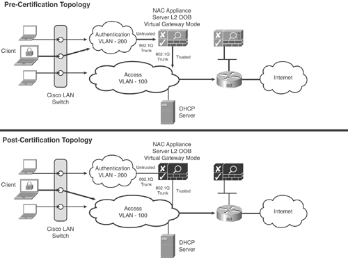
These certification steps are based on the perspective of the host and user in Figure 4-13. The host has Clean Access Agent installed and is Layer 2 adjacent to NAC Appliance Server. NAC Appliance Server is in Virtual Gateway mode and bridging between the untrusted and trusted networks. NAC Appliance is not configured for network scanning, only Clean Access Agent posture assessment. The Cisco LAN switch is configured to send both linkup or linkdown and MAC-notification SNMP traps to NAC Appliance Manager. NAC Appliance Manager is set up for OOB control of the Cisco switch. This example shows NAC Appliance failing open.
Figure 4-13. OOB in L2 Virtual Gateway Mode
Note
NAC Appliance recognizes both VLAN IDs and names as valid VLAN values. This allows you the flexibility of using either the ID (for example, 100) or the name (for example, Authentication-VLAN) when defining your VLAN values.
Initial Steps for OOB Clients
The initial steps for OOB clients are as follows:
1. The host plugs into an Ethernet switch port.
2. The switch immediately sends linkup and MAC-notification SNMP traps to NAC Appliance Manager. These traps include the MAC address of the client and the port number it is plugged into.
3. NAC Appliance Manager checks to see whether the MAC address is already certified (that is, whether it is on the certified list). In other words, is the client certified but logged off the network? If true, you can either put the client on the access VLAN or force the user to authenticate again by putting the client on the authentication VLAN. The client will go through authentication again but not certification. This is because the client remains on the certified list. After it is authenticated, the client is put on the access VLAN and is considered out-of-band.
4. If the client is not on the certified list, NAC Appliance Manager sends an SNMP write to the switch. This SNMP write tells the switch to move the client's switch port to the authentication VLAN, which in this example is 200. The exact VLAN number is determined based on the port profile for that switch port.
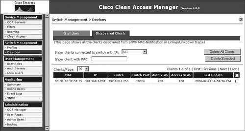
5. NAC Appliance Manager adds the client to its out-of-band discovered clients list. This list shows all the clients discovered from SNMP MAC-notification or linkup or linkdown traps. Figure 4-14 shows a sample OOB discovered clients page.
Figure 4-14. Out-of-Band Discovered Clients Page
6. At this point, the client is on VLAN 200, which is the untrusted side of NAC Appliance Server. All traffic from the client is now forced to pass through NAC Appliance Server by the network. NAC Appliance Server is configured to allow only certain traffic types through to its trusted side. Common examples are DHCP requests and DNS queries.
7. The client requests a DHCP address.
8. The request is seen by NAC Appliance Server on its untrusted interface (VLAN 200.) Because it is not a denied traffic type, it is retagged for VLAN 100 and forwarded out its trusted interface. The DHCP request continues on to a DHCP server. This VLAN retagging happens based on the preconfigured rules in NAC Appliance Manager's VLAN mapping tables. In this example, there is a rule to retag traffic from VLAN 200 to VLAN 100 and another rule to retag return traffic from VLAN 100 to VLAN 200.
9. The DHCP request is received by the DHCP server in access VLAN 100. From the DHCP server's viewpoint, this request has come from a client on VLAN 100. As such, it replies to the client with an IP address in VLAN 100.
10. NAC Appliance Server receives the DHCP reply on its trusted interface. It then retags the reply from VLAN 100 to VLAN 200 and forwards the DHCP reply to the originating client.
11. The client now has an IP address in the authentication VLAN that is part of the same subnet as the access VLAN. This is allowed because NAC Appliance is bridging, not routing, between the two VLANs.
Clean Access Agent Authentication Steps in OOB
The Clean Access Agent authentication steps in OOB are as follows:
1. The client is now a member of the NAC Appliance Unauthenticated role. By default, hosts in this role are not allowed to send any traffic, except DHCP and DNS queries, through their local NAC Appliance Server. You can modify the allowed traffic list as necessary for your environment.
2. Clean Access Agent, noticing the network connectivity, begins to send SWISS discovery packets to its default gateway. The agent is trying to locate a NAC Appliance Server.
3. NAC Appliance Server, listening on the SWISS ports, intercepts the request and checks to see whether the host is already authenticated. Because it is not, NAC Appliance Server responds with the equivalent of an, "I'm here; you need to log in" message.
4. NAC Appliance Server's reply message prompts the host's Clean Access Agent to pop up its login dialog box on the user's screen.
5. The user enters a username (Liam), password, and optionally an authentication provider, and then clicks Log In. An authentication provider defines the user database that NAC Appliance will use to verify authentication. In this example, the local user database will be used.
6. Liam's login credentials are forwarded by NAC Appliance Server to NAC Appliance Manager for verification.
Agent Host Security Posture Assessment Steps for OOB
The agent host security posture assessment steps for OOB are as follows:
1. After user authentication succeeds, NAC Appliance Manager moves to stage two: host security posture assessment. The user group that Liam is a member of determines the login role he is in. The user's login role determines what host security checks will be performed.
2. NAC Appliance Manager tells NAC Appliance Server to tell Clean Access Agent what security checks to perform on the host.
3. Optionally, the user is shown the acceptable use policy for the normal login role.
4. Clean Access Agent performs these checks and sends the results back to NAC Appliance Server, which forwards them to NAC Appliance Manager for certification.
5. If the host passes all Clean Access Agent security checks, skip to the "Agent Post-Certification Steps for OOB" section.
6. For any failed checks, NAC Appliance Manager instructs NAC Appliance Server to tell Clean Access Agent to pop up a remediation dialog box on the user's screen. This dialog informs the user of the issue found and how to fix it.
7. NAC Appliance Manager moves the user's role from Unauthenticated to Clean Access Temporary.
8. All traffic permitted for remediation is allowed through NAC Appliance Server. NAC Appliance Server retags the remediation traffic from the authentication VLAN to the trusted side, which is the access VLAN. VLAN retagging happens here just as in the initial steps covered earlier.
9. The user then takes the necessary actions to fix the issues found. Failed checks are presented for remediation one at a time. The user cannot continue to any subsequent failed checks until the current one is solved (unless it is an optional requirement).
Agent Post-Certification Steps for OOB
The agent post-certification steps for OOB are as follows:
1. The host is now considered certified or clean and is put into its proper normal login role.
2. At this point, NAC Appliance Manager instructs the switch to move the client's switch port from the authentication VLAN 200 to the access VLAN 100. The access VLAN value is specified in the port profile.
3. The client is now considered out-of-band. This is because the client's traffic no longer flows through NAC Appliance. It is routed and switched normally by the network.
4. Because the original IP address given to the client came from and is valid on the access VLAN, the client does not need to change it now.
5. NAC Appliance Manager adds the client to the out-of-band online user list and the user and host to the certified devices list.
Login Steps for OOB in L3 Adjacency, Real IP Mode
These certification steps are based on the perspective of the host and user in Figure 4-15. The traffic control method used is policy-based routing. The host has Clean Access Agent installed and is multiple Layer 3 hops from NAC Appliance Server. NAC Appliance Server is in Real IP Gateway mode and routing between the untrusted and trusted networks. NAC Appliance is not configured for network scanning, only Clean Access Agent posture assessment. The Cisco LAN switch is configured to send both linkup and linkdown and MAC-notification SNMP traps to NAC Appliance Manager. NAC Appliance Manager is set up for OOB control of the Cisco switch. The routers in the network are configured to policy route all traffic in the authentication VLAN to the untrusted interface of NAC Appliance Server.
Figure 4-15. Out-of-Band in Layer 3 Real IP Gateway Mode
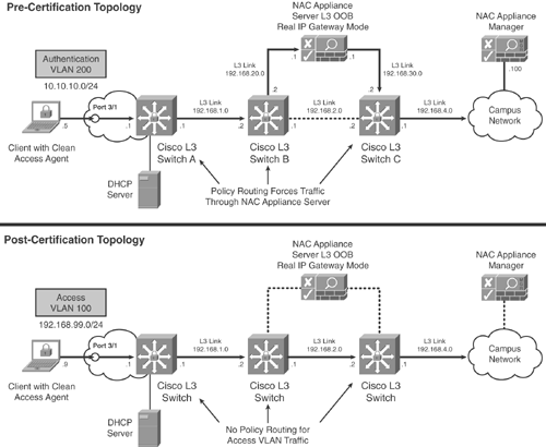
Initial Client Steps for L3 OOB
The initial client steps for L3 OOB are as follows:
1. The host plugs into switch A port 3/1.
2. The switch immediately sends linkup and MAC-notification SNMP traps to NAC Appliance Manager. These traps include the MAC address of the client and the port number it is plugged into.
3. NAC Appliance Manager checks to see whether the MAC address is already certified (that is, already on the certified list). In other words, is the client certified but logged off the network? If true, you can either put the client on the access VLAN 100 or you can force the user to authenticate again by putting the client on the authentication VLAN 200. If put back on the access VLAN, the client bypasses the NAC process. If put on the authentication VLAN, the client is authenticated again but does not go through the certification process. After it is authenticated, the client is put on the access VLAN and is considered out-of-band.
4. If the client is not on the certified list, NAC Appliance Manager sends an SNMP write to the switch. This SNMP write tells the switch to move the client's switch port 3/1 to the authentication VLAN, which in this example is 200. The exact VLAN number is determined based on the port profile for that switch port.
5. NAC Appliance Manager adds the client to its out-of-band discovered clients list. This list shows all the clients discovered from SNMP MAC-notification or linkup or linkdown traps. Figure 4-12 shows a sample OOB discovered clients page.
Steps to Obtain an IP Address in L3 OOB
The steps to obtain an IP address in L3 OOB are as follows:
1. At this point, the client switch port is on VLAN 200.
2. NAC Appliance Server is configured to allow only certain traffic types through to its trusted side. These firewall rules are called network filters. Common examples of allowed traffic are DHCP requests and DNS queries.
3. The client requests a DHCP address.
4. A Cisco IOS DHCP relay agent is configured on Cisco L3 switch A for the authentication VLAN. The DHCP relay agent changes the client's DHCP broadcast into an IP unicast and forwards it to the DHCP server's address. This address is specified using the ip helper-address interface configuration command on the Cisco switch. For more information, go to http://www.cisco.com and search for IOS DHCP Relay Agent.
Tip
A design best practice is to use the existing DHCP server in the network. A new DHCP scope should be created for the authentication VLAN. If a DHCP server is not available, NAC Appliance Server can be used.
5. The relayed DHCP request is received by the corporate DHCP server. From the DHCP server's viewpoint, this request has come from a client on the authentication VLAN 200. As such, it replies to the client with an IP address in VLAN 200.
6. The client now has an IP address in the authentication VLAN of 10.10.10.5/24. The client's default gateway is set to 10.10.10.1.
Client Authentication and PBR Steps in L3 OOB
The client authentication and PBR steps in L3 OOB are as follows:
1. The client's Clean Access Agent, noticing the network connectivity, begins to send Layer 2 UDP port 8905 SWISS discovery packets to its default gateway. The agent is trying to locate a NAC Appliance Server.
2. Because there is no NAC Appliance Server between the Clean Access Agent and its default gateway, it does not get a response.
3. Clean Access Agent then tries Layer 3 SWISS discovery. Clean Access Agent sends UDP port 8906 unicast packets to its configured discovery host. The discovery host is NAC Appliance Manager in this example, but it can be set to any host on the trusted side of NAC Appliance Server.
4. The Clean Access Agent includes the host's MAC address in the discovery messages.
5. Because the client is not L2 adjacent to NAC Appliance Server, Cisco IOS PBR or VRF features must be used. PBR and VRF ensure that all authentication VLAN traffic is forced to follow a predetermined network path that goes through NAC Appliance Server. This example will use policy-based routing.
6. The configuration for policy-based routing on Cisco L3 switch A would look something like Example 4-4.
Example 4-4. PBR Sample Configuration
access-list 1 permit ip any
!
interface vlan 200
ip policy route-map auth-vlan
!
route-map auth-vlan permit 10
match ip address 1
set ip next-hop 192.168.1.2
This configuration instructs switch A to send all IP traffic coming in on interface VLAN 200 to switch B's 192.168.1.2 interface. This PBR policy effectively prevents any host on the authentication VLAN from going anywhere except to switch B.
Tip
Each L3 device between the authentication VLAN and NAC Appliance Server must have PBR configured appropriately. Do not forget to make sure that the client's return traffic is also forced to go through NAC Appliance Server. This can be done using routing tables, PBR, or VRF.
7. Clean Access Agent's Layer 3 SWISS discovery packets are routed to NAC Appliance Server (10.10.20.1) via policy-based routing.
8. NAC Appliance Server, listening on the SWISS ports, hears the request and checks to see whether the host is already authenticated. Because it is not, NAC Appliance Server responds with the equivalent of an "I'm here; you need to log in" message.
9. NAC Appliance Server's reply message prompts the host's Clean Access Agent to pop up its login dialog box on the user's screen.
10. The user enters a username, password, and optionally an authentication provider, and then clicks Log In. An authentication provider defines the user database NAC Appliance will use to verify authentication. In this example, the local user database will be used.
11. The user's login credentials are forwarded by NAC Appliance Server to NAC Appliance Manager for verification.
Client Certification and Post-Certification Steps in L3 OOB
The client certification and post-certification steps in L3 OOB are as follows:
1. After the user passes authentication, client certification is performed. This process is almost identical to the in-band certification process found in the "Agent Host Security Posture Assessment Steps for OOB" section. The one difference is that in L3 OOB mode, policy-based routing is used to ensure that NAC Appliance Server is in-band for all client traffic in and out of the authentication VLAN. This is regardless of the user's role (that is, quarantine, temporary, and so on).
2. After the client passes certification, NAC Appliance Manager matches the MAC address received from Clean Access Agent with a MAC address sent via a MAC-notification SNMP trap. When a match is made, NAC Appliance Manager looks into the MAC-notification trap to find the switch port information.
3. Now that NAC Appliance Manager has a complete MAC/IP/port mapping, it instructs switch A to change port 3/1 to access VLAN 100.
4. NAC Appliance Manager instructs the client to perform DHCP release/renew operations. Optionally, NAC Appliance Manager instructs the switch to bounce port 3/1. Either of these methods forces the client to erase its current IP address and request another one. DHCP release/renew is the preferred method.
5. The client sends out a DHCP request on access VLAN 100. It receives a new IP address of 192.168.99.9/24 with a default gateway of 192.168.99.1.
6. The client is now considered out-of-band. Traffic flows through the network unrestricted because no PBR policies are configured for access VLAN traffic. NAC Appliance is now totally out of the picture.
Advantages of Using Out-of-Band Mode
When designing any security solution, it is important to understand the advantages and disadvantages of the various product features and modes of operation. There are several compelling reasons to use Out-of-Band mode instead of In-Band mode. The following is a list of Out-of-Band mode's major advantages:
- Typically the biggest advantage OOB has over IB is that client traffic no longer flows through NAC Appliance after authentication and certification are complete.
- OOB provides true switch port–level Network Admission Control. Given that OOB uses VLANs to dynamically control client traffic at the switch port–level, it could be considered more secure than IB. With In-Band mode, there is only a single policy enforcement point: NAC Appliance Server. With Out-of-Band mode, there are two policy enforcement points: the switch port VLAN and the NAC Appliance Server.
- NAC Appliance OOB poses no throughput limitations on traffic while the client is on the access VLAN.
- NAC Appliance is removed from being a single point of failure in the traffic path while the client is on the access VLAN.
- OOB mode allows administrators to configure NAC Appliance to fail-open (sort of). If the server fails in In-Band mode, all traffic from the untrusted side stops flowing regardless of the client's certification status. If the server fails in Out-of-Band mode, all hosts remain in the VLAN configured on their switch port. This means anyone already on an access VLAN sees no impact. But anyone on the authentication VLAN is blocked from network access.
Disadvantage of Using Out-of-Band Mode
Out-of-Band mode has a few disadvantages when compared to In-Band mode. These disadvantages should be checked against your security policy and network environment requirements for relevancy. The following is a list of the major disadvantages:
- Out-of-Band requires specific Cisco switches and software versions be used. See the "Switches Supported by NAC Appliance Out-of-Band" section in this chapter for details.
- OOB works only in wired LAN environments where VLANs can be used. Wireless and VPN clients are not currently supported in Out-of-Band mode.
- The ability to control traffic by using bandwidth limiting and traffic filtering after the client is certified is not available in OOB mode. This is because traffic does not flow through NAC Appliance after clients are in the access VLAN. External controls such as Cisco IOS QoS and ACLs may be used instead.
- OOB requires privileges to manage and change the configuration on the Cisco switches that NAC Appliance will control. This is done through the use of SNMP.
- Due to conflicts, Out-of-Band mode and 802.1X cannot coexist on the same switch ports.
- Switch clusters are not supported in OOB mode. However, OOB mode does support Cisco's StackWise technology. The workaround is to assign a unique IP address to each switch in the stack.
Where You Can Use Out-of-Band Mode and Where You Cannot
NAC Appliance Out-of-Band excels when deployed in campus LAN environments with lots of access-layer switch ports. OOB mode can be used only in wired switched LAN environments that can support VLANs. Additionally, you must use a supported Cisco switch and software version. NAC Appliance Out-of-Band mode cannot be used in wireless, VPN, 802.1X, or any non-Cisco switched environments. Note that 802.1x will be supported in a future release.
Switches Supported by NAC Appliance Out-of-Band
This section details the Cisco switch models and the required minimum software version you must have in your environment if you plan to use NAC Appliance in Out-of-Band mode. This information is constantly being updated, so be sure to check the latest NAC Appliance Release Notes on http://www.cisco.com. Table 4-3 lists the supported switches as of this writing.
Table 4-3. Supported Switches for Cisco NAC Appliance Out-of-Band
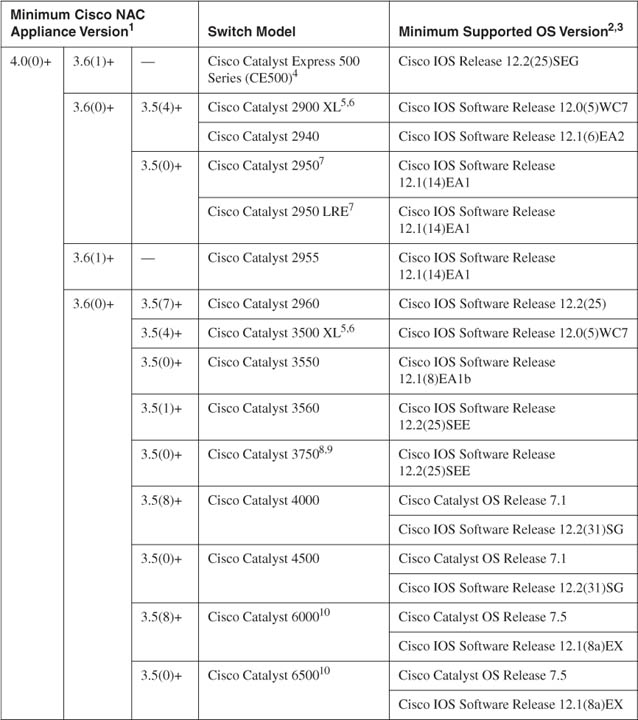
Clean Access Agent and Web Login with Network Scanner
This section will deal with how to best use the web login with Network Scanner and Clean Access Agent in your Cisco NAC Appliance design. Understanding where and when to use Clean Access Agent or web login is critical to producing a successful design. For this discussion, it should always be assumed that web login will include the Network Scanner function. The Network Admission Control Appliance solution has three main functions: authentication, posture assessment, and remediation. Each of these functions requires the NAC Appliance solution to interact with the clients it is attempting to control. Each of the main functions requires client information and interaction that is unique to their purpose. The agent and web login differ in their capabilities to gather information and interact with a client. An examination of these differences will help in the decision-making process of which approach to use for a given situation.
The first function's purpose, authentication, identifies who is connecting to the network. Authentication requires the gathering and validating of a user's credentials, typically username and password. Authentication can also include performing the SSO process. Both Clean Access Agent and web login can perform basic authentication. However, only the Clean Access Agent can perform the duties of SSO. As a result, if you choose to use any of the SSO methods, VPN, Wireless, or AD, you must use Clean Access Agent for authentication. A nice feature of Clean Access Agent is that it self-discovers when the user needs to authenticate to NAC Appliance and pops up a Windows dialog box to do so. Web login has no equivalent discovery function. It requires the user to know when to open a web browser to log in. Figure 4-16 shows the Clean Access Agent Login dialog box.
Figure 4-16. Clean Access Agent Login
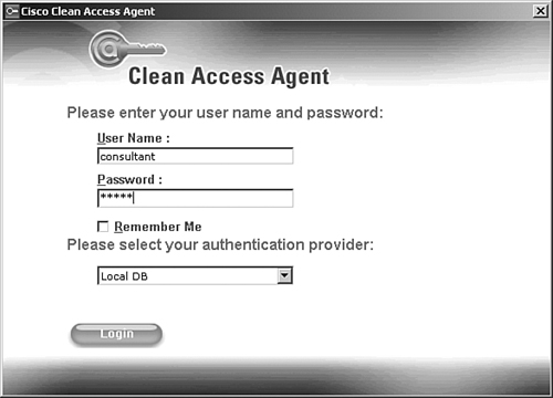
Web login is shown in Figure 4-17.
Figure 4-17. Web Login Authentication
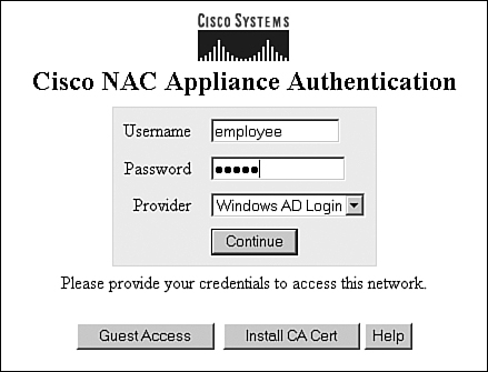
The second main function is posture assessment of the user's host PC. Posture assessment involves validating that a given host complies with the requirements set forth in your host security policy. To accomplish this task, NAC Appliance gathers relevant information about the host and compares it against the requirements set forth in the host security policy. Both Clean Access Agent and the Network Scanner part of web login are capable of performing a host posture assessment. However, Clean Access Agent is by far the more widely deployed of the two. During the creation of your host security policy, you will determine what host posture assessment checks you want to perform. Based on those checks, ask yourself these questions:
- What information do I need to gather to perform the checks?
- Where is this information stored? Can it be accessed using a network scan, or must it be gathered by a local agent? If both, which is easiest?
- Will hosts have personal firewalls enabled that will thwart the NAC Appliance network scanner?
- If the information is only available locally, the agent must be used. Are all the clients running operating systems that the Clean Access Agent supports?
- The installation of Clean Access Agent requires the user to have admin rights. Will users have the admin rights necessary to install Clean Access Agent on their PC? If not, a software distribution method, such as Short Message Service, should be used.
- One way to get around the previous requirement is to distribute an agent stub first. A stub provides a convenient way to allow users to install Clean Access Agent without admin rights. But the stub program itself requires the network administrators to have admin rights on the PC it will be installed on. Do you control or have admin rights on all the PCs you want to control?
- How will the posture assessment checks change based on user role and host location? For example, in the public areas you might want to scan only for infected hosts and not use an agent.
Clean Access Agent is built to do local checks of a host's file system, registry, running services, and applications. Clean Access Agent provides an effective mechanism to allow NAC Appliance to check for things such as the running state of antivirus clients, virus definition file versions, Windows hotfixes and service packs, and so on. Figure 4-18 shows Clean Access Agent kicking off its posture assessment process.
Figure 4-18. Clean Access Agent Posture Assessment
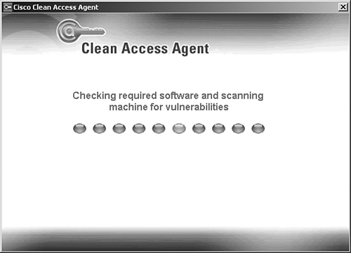
The Network Scanner function is built to scan a host to detect known security vulnerabilities and active worm infections. Nessus is the scanning engine used by Network Scanner. Network Scanner has hundreds of vulnerability plug-ins for you to choose from. For example, you can run plug-ins that scan to see whether a host is infected with the Zotob worm or is vulnerable to a dcom buffer overflow attack. The big downside of Network Scanner is that it performs the scans from the NAC Appliance Server across the network to the host. This means that simple things like a host personal firewall or Intrusion Prevention System will block Network Scanner from gathering any information. Figure 4-19 shows the vulnerability report screen that web login displays.
Figure 4-19. Web Login Vulnerability Report
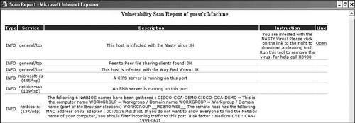
The purpose of the third function, remediation, is to provide noncompliant users with the necessary tools and information they need to become compliant. This requires that NAC Appliance be able to deliver the tools and information to the user and be able to validate that the changes required for compliancy were completed. Both the agent and the network scanner function of web login are capable of performing the remediation function. However, the capabilities of Clean Access Agent are far superior to Network Scanner. Clean Access Agent's remediation process walks the user through each individual failed check. This is done using a pop-up Windows dialog box. This dialog box contains information and instructions pertaining to the failed check. It also contains a remediation button. This button can link to web pages, download files, or start windows or antivirus update programs. Clean Access Agent recognizes when a user completes a fix and when the host becomes compliant. After the user is compliant, Clean Access Agent notifies NAC Appliance, which then grants the client access to the network.
Network Scanner works a little bit differently. After performing its vulnerability scan, a web page containing all the vulnerabilities found is displayed on the client's PC. Instructions and a URL link are provided for each vulnerability listed. Unlike Clean Access Agent, this method does not support the launching of any update programs—antivirus, Windows, and so on—on the host machine. In addition, the capability to recognize when a user completes a fix is not automatic. The user must log out and log in to be rescanned.
As discussed, NAC Appliance interacts with and gathers information from clients in three ways: through Clean Access Agent, Web Login, or both. Either method can be used to accomplish the three main functions—authentication, posture assessment, and remediation—as set forth in the preceding discussion. By and large, the Clean Access Agent method is the recommended design choice. However, both Clean Access Agent and web login have advantages and disadvantages. A good rule of thumb is to use Clean Access Agent on hosts that you or the users have admin rights on. Using web login is a popular choice for guest users that will be given extremely limited access to your internal resources, such as Internet only. And, of course, web login is used for hosts that you cannot install Clean Access Agent on.
The type of interaction method chosen is role dependent. For a given role, both Clean Access Agent and web login can be made available or Clean Access Agent can be made mandatory. For example, the Guest role users might have both methods available, but the Employee role users must use the Clean Access Agent.
Summary
This chapter examined the various design options available in a Cisco NAC Appliance deployment. The function and pros and cons of each option were studied in detail. The following design options were covered:
- Single-Sign-On
- In-band
- Out-of-band
- Layer 2 adjacency
- Layer 3 adjacency
- Virtual gateway mode
- Real IP gateway mode
- Clean Access Agent
- Web login and Network Scanner