Chapter 5. Advanced Cisco NAC Appliance Design Topics
This chapter covers the following topics:
- External Authentication Servers
- Single Sign-On
- NAC Appliance and IP Telephony Integration
- High Availability and Load Balancing
This chapter will build on the basic NAC Appliance design concepts covered in the preceding chapter. It focuses on those advanced features essential to designing the most secure, user-friendly, scalable, and fault-tolerant NAC Appliance environment possible. This chapter by no means covers all the advanced features available, but instead focuses on the most widely deployed, or popular, advanced options. You will undoubtedly use most of these options in your design. The use of external authentication servers and high availability as design options is highly recommended. Be sure to read through those sections to get a good idea of the choices available to you.
External Authentication Servers
A key component of the NAC process is user authentication. In fact, identifying, or authenticating, who is connecting to the network is the first step in the NAC Appliance process. A user's identity determines which user role that user will be a member of. The user role in turn determines or influences almost every other NAC process. For example, if you are user John Doe, you are a member of the Employee user role. Everyone in the Employee user role is scanned for the latest hotfixes and, if clean, is granted unlimited network access.
In most environments, building a local user database in NAC Appliance is not practical given the sheer amount of users. Except for perhaps in test and guest environments, an external authentication server should be used to authenticate users. The process that NAC Appliance goes through when authenticating is pretty straightforward. It starts with the user typing in credentials to log in to NAC Appliance. These credentials, a username and a password, are sent from NAC Appliance Manager to the external authentication server. The external authentication server then validates the user credentials against its user database and return a pass or fail result to NAC Appliance Manager.
NAC Appliance can optionally be configured to request a specific attribute's value from the authentication server. The attribute's returned value can then be used to determine what user role a particular client should be made a member of. For example, for any particular user, NAC Appliance can query the external authentication server for the value of the attribute group membership. If the authentication server returns a value of domain users, this user is put into the Employee user role of the NAC Appliance solution. Here is the complete process of authentication when an external authentication server is used:
Step 1. The user connects to the network.
Step 2. The user supplies credentials, username, and password, using either web login or Clean Access Agent.
Step 3. These credentials are sent to NAC Appliance Server, which forwards them on to NAC Appliance Manager.
Step 4. NAC Appliance Manager sends the user's credentials to the external authentication server.
Step 5. The external authentication server validates the credentials and sends a pass or fail result to NAC Appliance Manager.
Step 6. If the credentials pass, NAC Appliance Manager can optionally request the value(s) of some attribute(s) from the external authentication server.
Step 7. NAC Appliance will then use the received attribute values to map the user into a user role. An example of the attribute-to-role mapping configuration screen is shown in Figure 5-1.
Figure 5-1. Role Mapping Configuration Screen

Several of the most popular authentication server types are supported by NAC Appliance. Here are the supported external authentication server types:
- Remote Authentication Dial-In User Service (RADIUS)
- Lightweight Directory Access Protocol (LDAP)
- Kerberos/Active Directory
Note
Windows NT LAN manager (NTLM) is still supported, but because Windows NT is end-of-life, this type will not be covered.
One or more authentication server types can be used simultaneously within a NAC Appliance solution. If you configure two or more authentication servers, NAC Appliance uses the provider field to determine which authentication server a particular user wants to use. A provider is a configured authentication server. You configure web login and Clean Access Agent to display a list of available providers to the user. Be sure to use provider names that your user community will understand. The user then must choose a server from a drop-down list, called the provider list. Figure 5-2 shows an example of a web login drop-down provider list.
Figure 5-2. Web Login Provider List

Mapping Users to Roles Using Attributes or VLAN IDs
Probably the most complex external authentication server design option you will deal with is mapping users to a user role. During the design phase, you will want to determine how many user roles you will need and how you will map users into these roles. For example, if you want faculty and students to be granted different network access privileges, you will need two roles: faculty and students. Then you could use the returned value of an LDAP group membership query to assign the users to their proper role. If the LDAP query returns a value of faculty, the Faculty role is used. Traffic policies are then used to determine how much network access a particular role is allowed. Three parameters can be used to assign a user to a role:
- VLAN ID NAC Appliance uses the virtual LAN (VLAN) ID of the user traffic on the untrusted side of NAC Appliance Server.
- Authentication attributes NAC Appliance uses the values of various attributes passed from LDAP, Cisco VPN, and wireless devices, or RADIUS servers.
- Default role If the previous two parameters are not configured or receive no match, the user is put into the default role configured for that external authentication server.
NAC Appliance uses a set of mapping rules to determine which user maps to which role. Cisco NAC Appliance allows the administrator to specify complex Boolean expressions when defining mapping rules. Mapping rules are broken down into conditions. You can combine these conditions using Boolean operators to create a string of criteria. For example, a user is a member of the Employee role if his VLAN ID is 100 and the LDAP query returned a group membership of either employee-USA or employee-Asia and a company value of acme corp. As you can see, a mapping rule can be as simple or as complex as you need it to be for your environment. During the design phase of NAC Appliance, you will want to determine what your mapping rules will look like.
Here are some of the most common attributes used in mapping rules for RADIUS and LDAP:
- RADIUS Commonly used attributes are as follows:
— IETF class [025] If so configured in RADIUS, you can use the class attribute string value to identify which RADIUS group a user is a member of.
— User_Name Can be used to map a username to a user role.
— NAS_IP_Address Can be used to map all users on a given virtual private network (VPN) concentrator to a user role. For example, all users on the B2B VPN concentrator map to the B2B user role, whereas all users on the employee concentrator map to the Employee-VPN user role.
An example of a RADIUS mapping rule is shown in Figure 5-3. Unlike LDAP, a RADIUS rule provides you with a list of attributes to pick from.
Figure 5-3. Mapping Rule Example for a RADIUS Server

- AD LDAP Commonly used attributes and value examples are as follows:
— memberOf Sample values are CN=employee-asia, CN=Users, DC=jheary, DC=com.
— company Sample value is ACME Corp.
— department Sample value is Engineering.
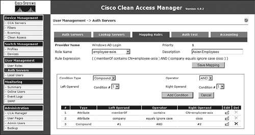
Figure 5-4 shows an example of a compound mapping rule for an AD LDAP Server. Notice the rule logic says that both conditions #1 and #2 must be true for the rule to succeed. If it succeeds, the user is mapped into the employee-Asia user role.
Figure 5-4. Mapping Rule Example for an LDAP Server
Tip
An LDAP browser program allows you to find, and verify the spelling of, all the available attributes in a given LDAP server. Many free LDAP browsers are available at sites like http://www.downloads.com.
MAC Address Authentication Filters
In some cases, you will want to bypass authentication, posture assessment, role assignment, or any combination thereof for certain network devices or users. NAC Appliance relies on matching the device's MAC address or MAC/IP address pair to determine whether bypass is enabled. Common examples of bypassed device types are printers, IP phones, servers, nonclient machines, and network devices. Another less common use of MAC Address filtering is for allowing corporate desktops to bypass authentication and perform only posture assessment and role assignment. By doing this, you can save the end user the time and hassle of performing authentication but maintain the security that posture assessment and user roles provide. The MAC filter example shown in Figure 5-5 allows corporate PCs to bypass authentication and move directly to posture assessment and role assignment. Given that client desktops typically use DHCP for their IP address, only the MAC address is used to identify hosts. If this were a statically addressed host, both the MAC/IP pair would be used.
Figure 5-5. MAC Filter with Checking

Figure 5-5 shows the client access type options. As you can see, you can use five different access types. Each access type gives a description of what actions it will take. These actions can differ between in-band (IB) and out-of-band (OOB), so the actions are separated out accordingly. Pay special attention to how the OOB VLAN is assigned because it differs for each access type.
When using Out-of-Band mode, it is very important to add all your IP phones to this MAC filter list and set them to ignore. For In-Band mode, it is recommended that you configure your network to have all voice traffic bypass the NAC Appliance solution altogether. However, if this is not possible, you must import the MAC addresses of all the IP phones and set them to allow.
Single Sign-On
This section covers the design best practices for the various NAC Appliance–supported Single Sign-On (SSO) methods. SSO gives users the convenience of having to log in to the network only once. For example, without SSO enabled, a VPN user would have to enter credentials into the VPN client, connect, and then enter credentials again to the Clean Access Agent pop-up dialog. With SSO enabled, the Clean Access Agent uses the credentials supplied to the VPN client, thus eliminating that step and creating a one-time login user experience. Cisco NAC Appliance currently supports three methods of Single Sign-On:
- Active Directory SSO
- VPN SSO
- Cisco Wireless SSO
Making the right SSO design decisions will help ensure a successful SSO deployment. The first decision is to pick which SSO method you would like to be able to use. This is not necessarily the method you will ultimately end up using, but the one whose use you would like to initially explore. This is arguably the easiest decision because it is mostly predetermined based on the access method of the client. If your clients are connecting through a NAC Appliance–supported VPN device, you would use VPN SSO there. If your clients are connecting through a supported Lightweight Access Point Protocol (LWAPP) wireless controller, you would use Wireless SSO. Finally, if your clients are logging in to a Windows Active Directory (AD) domain, you would use AD SSO. If your environment combines two of the supported access methods—wireless and AD login for instance—a good rule of thumb is to use the SSO method that would happen first. For example, clients in an environment that uses both wireless and AD Login access methods follow an order of operations. First the wireless connection is established, and then the AD login is performed. The best SSO method would be wireless SSO because the wireless connection happens first.
The selected SSO method must now be looked at in greater detail to make sure that it is the correct design choice for your environment.
Active Directory SSO
Cisco NAC Appliance 4.0 or greater supports Single Sign-On with Windows Active Directory. You can configure NAC Appliance to use a back-end Kerberos Domain Controller (Active Directory server) to automatically authenticate Clean Access Agent users. This feature permits users who are already authenticated to an Active Directory server to bypass the normal Clean Access Agent login and skip right to posture assessment and certification.
Active Directory SSO Prerequisites
The following are prerequisites for Active Directory SSO:
- NAC Appliance Clients must use the Clean Access Agent software.
- NAC Appliance 4.0 or greater software is required.
- Time must be synchronized between NAC Appliance and Active Directory servers.
- The supported AD servers are as follows:
— Windows 2000 Server SP4
— Windows 2003 Standard SP1
— Windows 2003 Enterprise SP1
— Windows 2003 Enterprise R2
How Active Directory SSO Works
The NAC Appliance Active Directory SSO process works by using the Kerberos ticket exchange process built into the Windows 2000 and 2003 server architecture. A NAC Appliance Server that will support AD SSO clients must have a username configured in Active Directory. You can share this username among multiple NAC Appliance Servers that will support SSO. This username must be set up to use DES encryption, not the default RC4. This is because the Linux OS on NAC Appliance Server does not support RC4 encryption.
To change the encryption for the NAC Appliance Server user, a program called ktpass.exe must be used. This program is a part of the Windows Support Tools and is available on the Windows Server CD or online at Microsoft.com. The NAC Appliance Server user and ktpass.exe program need to be set up only on the Domain Controller (DC) Server that the NAC Appliance Server will talk to. NAC Appliance Server will use this server for user authentication requests. So, if your AD domain has 10 DC servers, you have to run ktpass.exe only on the server that NAC Appliance Server is configured to use. In the design phase, you should pick which AD Domain Controller you will use for this purpose. Figure 5-6 shows the details of how AD SSO works with the Kerberos ticket exchange process.
Figure 5-6. Active Directory Single Sign-On Kerberos Exchange
After the Kerberos SSO process authenticates the user, NAC Appliance then performs user role mapping. NAC Appliance Manager sends an LDAP lookup request to the Active Directory Server. The results are run through the mapping rules, and the user is put into the correct NAC Appliance role. The NAC certification process now initiates. The host is checked to make sure that it meets the security requirements defined by the user's role.
Note
For a detailed explanation of the Kerberos ticketing process, see Microsoft's Kerberos website at http://www.microsoft.com/kerberos.
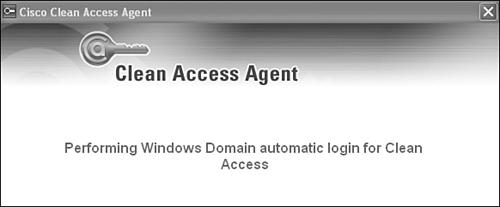
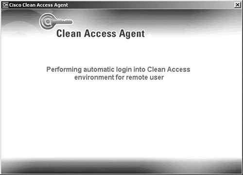
During the SSO authentication process, the end user sees the Clean Access Agent dialog box shown in Figure 5-7. This dialog box disappears after the end user passes authentication.
Figure 5-7. Clean Access Agent AD SSO Authentication Dialog Box
VPN SSO
For users who connect to the network through a supported VPN device, you can use the VPN Single Sign-On feature. This is similar to AD SSO in that the user authentication portion of the NAC Appliance process is transparent to the end user. Users logging in through their VPN client do not have to log in again to Cisco NAC Appliance. NAC Appliance leverages the VPN user credentials and any VPN user group and class attributes to map the user to a particular role.
VPN SSO Prerequisites
For VPN SSO to work, NAC Appliance Server must run in In-Band mode, and it is recommended, although not required, that the user have the Clean Access Agent installed. It is also recommended, but not required, that the NAC Appliance Server be placed directly behind or Layer 2 adjacent to the VPN device.
NAC Appliance supports VPN SSO with the following VPN devices:
- Cisco VPN 3000 Version 4.7
- Cisco ASA 5500 Series
- Cisco PIX 500 Series
- IOS Routers with security feature set
- Cisco VPN Client (IPsec)
- Cisco SSL VPN (full tunneling client)
Note
Cisco NAC Appliance supports any VPN device that uses and can send RFC-compliant RADIUS accounting messages to NAC Appliance. However, only the devices in the preceding list are officially supported by Cisco Technical Assistance Center. Be sure to check the NAC Appliance release notes at http://www.cisco.com for the latest details about the devices and codes supported with VPN SSO.
How VPN SSO Works
VPN SSO operates using a trust model. NAC Appliance trusts the VPN device to correctly perform user authentication for the client VPN tunnels. After this authentication is complete, the VPN device sends a RADIUS message to NAC Appliance with the necessary details of who just successfully authenticated. Given that NAC Appliance trusts the VPN device's messages, the VPN client is allowed to bypass NAC authentication and proceed directly to posture assessment or certification. Figure 5-8 shows how the VPN SSO process works.
Figure 5-8. VPN SSO Process
Here are the steps represented in Figure 5-8:
Step 1. The client PC sends a VPN tunnel request to the ASA VPN device. In this request is the username and password of the user.
Step 2. The ASA 5500 performs a verification of the user's credentials. If the user passes authentication, a VPN tunnel is established between the ASA and the client PC.
Step 3. The ASA sends a RADIUS accounting start message to NAC Appliance Server. A start message indicates that a new client has successfully passed authentication. This message also contains the client's IP address, username, and miscellaneous other RADIUS attribute values such as class [025]. During this process, the Clean Access Agent on the client machine pops up the dialog box shown in Figure 5-9.
Figure 5-9. VPN SSO Authentication Dialog Box
Step 4. At this point, NAC Appliance considers the user successfully authenticated. If user role mapping is configured, the server forwards the RADIUS attributes received from the ASA to the manager. For example, RADIUS attribute class = employee. The manager holds the mapping rule table that matches VPN users with NAC Appliance user roles.
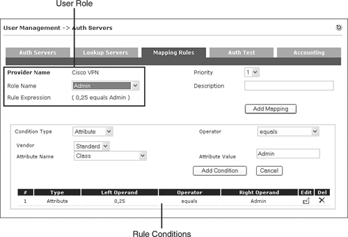
Step 5. NAC Appliance Manager performs a mapping rule table lookup using the RADIUS attributes it has received. After it finds a match, it maps that user into the matched user role. See Figure 5-10 for a sample mapping rule. This rule says that if the RADIUS attribute class [025] equals Admin, put this user in the user role Admin.
Figure 5-10. RADIUS Mapping Rule Configuration Screen
Step 6. NAC Appliance Server now performs the normal posture assessment or certification of the client. The security requirements for the client are dependent on the user's role. The posture assessment process is the same regardless of whether VPN SSO is used.
Step 7. The client is logged off NAC Appliance when a RADIUS stop record is received from the ASA.
Cisco Wireless SSO
In a supported wireless environment, it is recommended that the NAC Appliance perform SSO. This means that the end user will have to enter credentials into only the wireless client. These same credentials will then be used transparently to log on the user to NAC Appliance, thus bypassing the manual user authentication step. NAC Appliance performs wireless single sign-on in just about the same manner as it does VPN single sign-on. It uses a trust relationship between the Airespace wireless LAN controller (WLC) and NAC Appliance. NAC Appliance trusts the user authentication results reported by the WLC. NAC Appliance logs a user on when it receives a RADIUS start record. NAC Appliance logs a user off when it receives a RADIUS stop record.
Cisco Wireless SSO Prerequisites
For wireless SSO to work, NAC Appliance Server must be running in In-Band mode. It is recommended, although not required, that the NAC Appliance Server be placed Layer 2 adjacent to the WLC.
NAC Appliance supports wireless SSO with Cisco Airespace 4400 Series Wireless LAN Controllers.
Note
Be sure to check the NAC Appliance release notes at http://www.cisco.com for the latest details about the devices and codes supported with wireless SSO.
How Cisco Wireless SSO Works
Figure 5-11 shows the process by which NAC Appliance performs single sign-on in a WLC environment.
Figure 5-11. Wireless SSO Process

Here are the steps shown in Figure 5-11:
Step 1. The client PC sends a wireless association/connection request to the 4400 WLC. This request contains the user's username and password for authentication.
Step 2. The 4400 WLC performs a verification of the user's credentials. If the user passes authentication, the client is permitted to associate to the wireless access point.
Step 3. The WLC sends a RADIUS accounting start message to NAC Appliance Server. A start message indicates that a new client has successfully passed authentication. This message also contains the client's MAC Address, IP address, username, and miscellaneous other RADIUS attribute values such as class [025]. During this process, the Clean Access Agent on the client machine pops up the dialog box shown previously in Figure 5-9.
Step 4. At this point, NAC Appliance considers the user successfully authenticated. If the optional role-to-attribute mapping rules are configured, NAC Appliance Server forwards the RADIUS attributes received from the WLC to the NAC Appliance Manager.
Step 5. NAC Appliance Manager matches the RADIUS attributes with a user role. After a match is found, the client is put into that role.
Step 6. The NAC Appliance Server now performs the normal posture assessment or certification of the client. The security requirements for the client are dependent on the user's user role. The posture assessment process is the same regardless of whether wireless SSO is used.
Step 7. The wireless client is logged off NAC Appliance when a RADIUS stop accounting record is received from the WLC.
NAC Appliance and IP Telephony Integration
With careful design and planning, NAC Appliance and IP telephony can coexist harmoniously. This section is dedicated to the design best practices of integrating NAC Appliance into an IP telephony environment. When designing NAC Appliance to work in an IP telephony environment, the ultimate goal is to have clients inspected by NAC Appliance while all voice traffic bypasses NAC Appliance completely.
The best practices that help accomplish this goal are most relevant when client PCs plug directly into IP phones behind a NAC Appliance Server or are on a switch controlled by NAC Appliance. If your clients do not connect directly to IP phones, it is recommended that you design your network so that the voice traffic completely bypasses the NAC Appliance solution. Because IP phones are not capable of performing NAC, they should not have to go through the NAC solution. Removing IP telephony in this way greatly reduces the complexity of your design. Given that voice should be on its own VLAN, separate from the client VLANs, this should be a relatively straightforward solution. Just make sure that all voice VLANs never pass through NAC Appliance Server. If you are using OOB mode, you must also ensure that the switch ports with IP phones attached are set to Uncontrolled in NAC Appliance. This means that NAC Appliance completely ignores these ports, letting their behavior remain unchanged.
When your environment includes clients that plug directly into IP phones, you have to pay special attention to how you design your NAC Appliance solution. Here are some best practices that will make your integration go smoothly. They are broken up into two groups: in-band and out-of-band. The groups correspond to the mode your voice-facing NAC Appliance Server is using.
IP Telephony Best Practices for In-Band Mode
Here are the design recommendations you should consider when your voice-facing NAC Appliance Server is running in In-Band mode:
- It is highly recommended that the network be configured in such a way as to allow all voice traffic to bypass the NAC Appliance Servers. NAC Appliance does not support quality of service (QoS) and adds small amounts of latency and jitter to any voice streams that flow through it.
- If it is not possible to allow voice to bypass NAC Appliance, be sure to exempt all voice subnets from NAC inspection. This can be done using Allow filters on NAC Appliance Manager. Given that the Allow filter uses the bandwidth management settings of the unauthenticated role, be sure to set the unauthenticated role's bandwidth setting to unlimited.
IP Telephony Best Practices for Out-of-Band Mode
If your voice-facing NAC Appliance Server is running in OOB mode, your design becomes a little bit more complex. This makes sense given that with OOB mode you are controlling the actual switch port that the IP phone and its connected client are attached to. The basic rule of thumb is that if you will not have a client connecting to an IP phone, make sure that the phone's switch port is still set to be controlled in NAC Appliance Manager. Use MAC address filters to identify and permit your IP phones. This practice ensures that rogue users cannot gain access by disconnecting an IP phone and plugging in a laptop. If your clients do connect directly to the IP phones, you should consider the following design recommendations:
- Set your switch profiles to never bounce a switch port.
- The MAC addresses of all IP phones must be added and maintained in NAC Appliance Manager's Filter list.
- If you use NAC Appliance in Layer 3 adjacency Out-of-Band mode, you must rely on the DHCP release and renew functionality built into the Clean Access Agent and web login applet.
- If you configure NAC Appliance to change port VLANs dynamically, you must rely on the DHCP release and renew functionality built into the agent and applet to change the client's IP address.
- Use the certified timer in environments where the clients connect to the IP phone and not the switch port.
- You must configure NAC Appliance and your switches to use the MAC Notification SNMP trap and not the Linkup SNMP trap.
The following paragraphs explain these recommendations in more detail.
Be sure to set your port profiles to never bounce a switch port. Switch port bouncing is used to force the client to renew its IP address when it transitions from the authentication VLAN to the access VLAN. However, if you bounced the switch port, it would take down your IP phone as well as your client. Instead of port bouncing, use either virtual gateway mode with the authentication and access VLAN being the same subnet (also called virtual gateway same IP subnet design), or rely on the DHCP release and renew feature built into the Clean Access Agent and web login applet.
The virtual gateway same IP subnet solution is designed to eliminate the client IP address change when moving from the authentication VLAN to the access VLAN. It works by forwarding the client's initial DHCP request to the access VLAN. This means that the client is given a legal address that works for both the authentication VLAN and access VLAN. Therefore, the client never has to change its IP address when it transitions between the authentication and access VLANs. If you choose the DHCP release and renew feature, the agent or web login applet will issue a DHCP release request followed by a DHCP renew request to the host operating system. This works basically the same way as running the ipconfig /renew command on a Windows PC.
The MAC addresses of all IP phones must be added to the NAC Appliance Manager's filter list. Set these MAC exceptions to Ignore, meaning that when NAC Appliance receives a MAC notification trap for an IP phone, it should ignore it and take no action. You can quickly populate the IP phone MAC Exception list by using the bulk administration tool in CallManager and by using MAC address wildcards.
The reason IP phones must be added to the exception list is because when a switch port is controlled using OOB mode, it sends a MAC notification SNMP trap every time a new MAC address is detected. This action does not differentiate between the IP phone connecting and the client PC attached to the IP phone connecting. Therefore, if the IP phone's MAC address is not ignored in the Filter list, NAC Appliance considers it a new client and changes the port's VLANs to the authentication VLAN. It will then wait forever for an authentication request from the new MAC address (the IP phone), but one will never come. This whole time, the client PC connected to this port is stuck on the authentication VLAN as well. It is important to note that the voice VLAN, or aux VLAN, and by extension voice traffic, is not affected by this behavior. Only the data VLAN is manipulated by NAC Appliance.
If you use NAC Appliance in Layer 3 adjacency Out-of-Band mode, you must rely on the DHCP release and renew functionality built into Clean Access Agent and web login applet. Version 4.1 or greater of this feature updates the client's IP address as it transitions from the authentication VLAN to the access VLAN. You cannot use the virtual gateway same IP subnet design referred to previously because it requires NAC Appliance to be Layer 2 adjacent to the clients.
If you configure NAC Appliance to set the access VLAN to the user role VLAN, you must rely on the DHCP release and renew functionality built into Clean Access Agent and applet to change the client's IP address. You cannot use the virtual gateway same IP subnet design. This is because each user role VLAN must have a unique IP subnet of its own. It is not possible for the single shared authentication VLAN to have the same IP subnet as the multiple user role access VLANs. All clients are initially put into a single authentication VLAN, where they receive an IP address. After clients become certified, they are moved to the access VLAN ID configured for their particular user role. As a result, the client must be forced to change its IP address to match the user role access VLAN. Given that port bouncing cannot be used to force this change, the only alternative is to use the DHCP release and renew feature.
You should use the certified timer in environments where the clients connect to the IP phone and not the switch port. This helps with the problem of removing stale users from the certified device list. NAC Appliance normally relies on the switch to send a linkdown trap to the NAC Appliance Manager when a user disconnects from the network. The NAC Appliance Manager then logs out the user previously connected to that port. Relying on the linkdown trap to log off users in an IP telephony environment poses a problem in that an IP phone is always up. When a client disconnects from the IP phone port, the switch never sees it. It still sees linkup on the port because the IP phone is plugged into it. Therefore, the switch never sends a linkdown trap when the client disconnects from the network. The result of this is that the Certified Devices list never ages out and users are never logged off NAC Appliance.
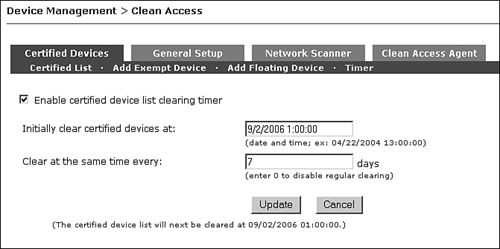
To address this issue, using the certified device timer is recommended. This feature clears the certified devices list at regularly scheduled intervals. This clearing is intrusive, however, because it moves the client's switch port back to the authentication VLAN. It then forces the user to reauthenticate and run through the certification process. Because of this, it is recommended that the clearing be done during nonbusiness hours and about every seven days. Figure 5-12 shows the Certified Devices Timer configuration page.
Figure 5-12. Certified Devices Timer Page
You must configure NAC Appliance and your switches to use the MAC Notification SNMP trap and not the Linkup SNMP trap. In an IP telephony environment where clients connect to IP phones, a linkup trap cannot be relied on as an indicator of when a new user connects to the network. This is because from the switch's point of view, it already has linked up with the IP phone and doesn't transition the link state for the user connecting through an IP phone. However, each time a new user connects to the phone port, the downstream switch port does learn the new user's MAC address and generates a MAC notification trap message.
High Availability and Load Balancing
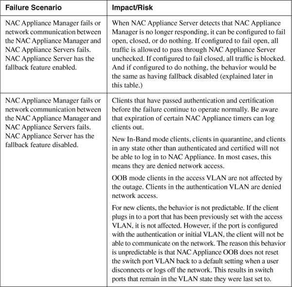
Maintaining a highly available and fault-tolerant network is paramount in today's high-tech world. The services that today's networks are providing have become engrained into even our most rudimentary daily routines. When these services go down, the impact can be devastating. This is why, when designing your NAC Appliance solution, special attention must be paid to making it as reliable as possible. To create a scalable and reliable design, you must first be aware of the impact and risk to the clients and services when pieces of the solution fail. To this end, some of the impacts and risks that a failure can bring will be discussed. After the risks are laid out, the various design options you can use to mitigate those risks are discussed.
There are three main components to a NAC Appliance solution: NAC Appliance Manager, NAC Appliance Server, and Clean Access Agent. If OOB mode is used, Ethernet switches can be added to the list of main components. Outside of the main components are the supporting components. This includes mechanisms such as authentication servers, VPN devices, wireless LAN controllers, log servers, routers, and general network availability. All these pieces, some more than others, can affect the availability and fault tolerance of a NAC Appliance solution. Table 5-1 examines some failure scenarios and their impact if no high availability features are used.
Table 5-1. NAC Appliance Failure and Risk Analysis

High Availability
There are several approaches to ensuring high availability and mitigating the failure risks described previously. The most popular are as follows:
- Stateful failover of NAC Appliance Manager
- Stateful failover of NAC Appliance Server
- Fallback feature on NAC Appliance Server
- Spanning Tree N+1
The following sections discuss these approaches in detail.
Stateful Failover of NAC Appliance Manager
The following are the prerequisites for stateful failover of NAC Appliance Manager:
- Must have two NAC Appliance Managers—one primary and one secondary.
- The two NAC Appliance Managers must be Layer 2 adjacent.
- Works with all NAC Appliance design options.
NAC Appliance Manager is the highest-risk component in the solution. This is because if it fails, all servers—up to 40 of them—are affected. It is highly recommended that you deploy the failover NAC Appliance Manager bundle. This includes two servers; one serves as the primary, and the other serves as the secondary. Under normal conditions, the primary server takes the entire workload. The secondary machine maintains state with the primary and constantly polls to make sure that the primary is working properly.
Two methods are used for polling. The first is a User Datagram Protocol heartbeat signal; the second is a serial heartbeat signal. In the event the primary machine fails, the secondary takes over. Clients are unaffected by the failure because all state information is known by the new primary machine. The old secondary machine is now the new primary; it remains the primary until it fails. After the old primary comes back online, it assumes the role of secondary machine.
The failover solution requires that both the primary and secondary machines be on the same IP subnet and should not be geographically separated. This is because they advertise a common IP address called a service IP address and exchange high availability information, such as heartbeat messages and configuration information, across a separate Ethernet crossover network. The service IP address is the virtual IP address that is advertised to NAC Appliance Servers and used for Secure Sockets Layer (SSL) certificate generation. The solution works very much like Hot Standby Router Protocol or Virtual Router Redundancy Protocol. The primary and secondary machines both have their own interface IP address but share a virtual service IP address.
To create the high-availability exchange network on which failover information passes, you put the second Ethernet port of both NAC Appliance Managers on an IP subnet that is not routed in your environment. This network can be built by using a simple Ethernet crossover cable and connecting the two NAC Appliance Managers or by creating a nonrouted VLAN on a switch. For extra resilience, you can enable the serial heartbeat signal by connecting the second serial port of each NAC Appliance Manager using a null modem cable. Figure 5-13 illustrates a high-availability design example.
Figure 5-13. High-Availability Design Diagram
The high-availability feature of NAC Appliance Manager detects the following failures of the primary NAC Appliance Manager:
- Power failure or shutdown of the primary NAC Appliance Manager
- Loss of heartbeat messages over eth1 or serial port
Stateful Failover of NAC Appliance Server
The following are the prerequisites for stateful failover of NAC Appliance Server:
- Must have two NAC Appliance Servers—one primary and one secondary.
- Two NAC Appliance Servers must be Layer 2 adjacent.
- Works with all NAC Appliance design options.
NAC Appliance Server supports stateful failover just like the NAC Appliance Manager does. It uses the same primary and secondary design in which the primary server takes the entire load and the secondary takes over if the primary fails. In addition to configuration and state sync, NAC Appliance Servers sync all DHCP information when they are configured as a DHCP server. Designing high availability into your NAC Appliance Servers is a best practice, especially in an in-band deployment where traffic always flows through it. Of course, the decision of whether to add high availability to a design requires a cost-to-risk analysis. This analysis should be done on a per-server basis given that each server will support different parts of the network, with some parts more critical than others. NAC Appliance Manager can control redundant servers and standalone servers simultaneously. This gives you the flexibility to use fault tolerance where it makes the most sense.
When configuring high-availability failover on a NAC Appliance Server pair, you can use the eth0 interface or a third Ethernet interface, eth2, if available. The heartbeat polling options, Ethernet and serial, work the same way as described previously for NAC Appliance Manager. Figure 5-14 shows a NAC Appliance Server high-availability design example.
Figure 5-14. NAC Appliance Server High-Availability Design Example

The high-availability feature of NAC Appliance Server detects the following failures of the primary NAC Appliance Server:
- Power failure or shutdown of the primary NAC Appliance Server.
- Loss of heartbeat messages over the eth1 or serial port.
- Loss of link on either eth0 or eth1.
- Link-based failover via icmp requests. If the Server cannot ping the configured host, failover occurs.
Fallback Feature on NAC Appliance Server
Starting in Version 4.1, NAC Appliance Server supports the fallback feature. This feature increases the fault tolerance of NAC Appliance during a communication failure between the NAC Appliance Server and NAC Appliance Manager. This communication failure could be the result of a failed manager, failed LAN or WAN segment, misconfigured access control list or firewall rule, or any number of things that could disrupt NAC Appliance Server to NAC Appliance Manager communications. The fallback server is configured per server, not globally. With the fallback feature enabled, NAC Appliance Server continuously monitors its connection with NAC Appliance Manager. When the connection fails, NAC Appliance Server can be configured to fall back to one of three states:
- Fail-open This state turns off the NAC checks and controls and allows all clients to go through that NAC Appliance Server.
- Fail-closed This state denies all clients access, regardless of their previous state from traversing the NAC Appliance Server.
- Do nothing This state's behavior would be the same as not turning on the feature. Those clients on the Certified list continue unaffected. New clients or clients in the quarantine phase are denied access.
The fallback feature of NAC Appliance Server detects the following failures of communication between NAC Appliance Server and NAC Appliance Manager:
- Power failure or shutdown of NAC Appliance Manager
- Loss of link on eth0 of NAC Appliance Manager
- A WAN or LAN failure that disrupts communication between NAC Appliance Server and NAC Appliance Manager
- Any fault software fault on NAC Appliance Manager that prevents it from responding to the fallback heartbeat messages
Spanning Tree N+1
The following are the prerequisites for Spanning Tree N+1:
- NAC Appliance Server must be in In-Band Virtual Gateway mode.
- NAC Appliance Server must not be configured for 802.1q trunking with VLAN mapping or with VLAN interfaces.
- You must use either Per VLAN Spanning Tree Plus (PVST+) or Multiple Instance Spanning Tree Protocol (MISTP) as the Spanning Tree Protocol (STP) algorithm.
It is possible to use the network to bypass a failed NAC Appliance Server and provide per-network load distribution among several NAC Appliance Servers. The goal is to distribute the client load, on a per-VLAN basis, among several NAC Appliance Servers and support an N+1 redundancy model. This is done using spanning tree and 802.1q trunks. It is important to note that the redundancy this solution provides is not stateful. As a result, clients moved to the backup NAC Appliance Server must go through authentication and certification again. This high-availability method is most common in large campus or wireless networks that abide by the access, distribution, and core layered network architecture.
The NAC Appliance Servers would be placed between the distribution and core layers. Figure 5-15 depicts just such a design.
Figure 5-15. NAC Appliance Load Balancing Using STP
As shown in Figure 5-15, NAC Appliance Servers are sandwiched between the distribution switch and the core switch. Clients plug into the access layer switches, which have an 802.1q trunk to the distribution switch. The distribution switch has three 802.1q trunks to the core switch. All the NAC Appliance Servers are configured for In-Band Virtual Gateway mode. They do not have 802.1q or any VLAN interfaces configured. They are simply acting as Layer 2 bridges with one notable exception: They will pass, unmodified, any bridge protocol data units (BPDUs) they receive from attached switches. BPDUs carry the STP information that switches exchange to determine the best Layer 2 paths. Because the BPDUs pass through NAC Appliance Server unmodified, the distribution and core switches believe that they have point-to-point 802.1q trunks between each other. They are not aware that NAC Appliance Server is in the middle.
The Spanning Tree Protocol distributes the load across the individual trunk links and provides failover in the case of a primary trunk failure. To accomplish this, STP uses the concept of path cost to determine which trunks are forwarding (active) and which are blocking for a given VLAN. STP calculates the path cost using two values: media speed (bandwidth) of the links and port cost (a value assigned to individual switch ports). Spanning Tree selects the best path based on the lowest path cost. The trunk with the lowest path cost is put into the STP forwarding state and begins passing traffic. All other alternate paths are put into the STP blocking state and pass no traffic.
The trunk going through standby server C in Figure 5-15 has had its port cost on both sides increased to the point that its path cost is higher than the cost of the other trunks. This results in the trunk being put into the STP blocking state for VLANs 1-4. The other two trunks are put into the forwarding state for the VLANs they carry. As a result, server A will take the client load for VLANs 1 and 2. Server B will take the client load for VLANs 3 and 4. And server C will act as the standby or backup server for all the active servers. Under normal conditions, server C does not receive client traffic. When a failure occurs with either server A or B, STP recalculates the path cost for the VLANs on the lost trunk. The trunk through server C will now have the lowest path cost available. STP will move this trunk from the blocking state to the forwarding state. Now all the VLAN traffic that used to pass over the failed trunk will be redirected to this new trunk. The result is that the standby server C will take the client load for the failed NAC Appliance Server.
The Spanning Tree N+1 method detects the following types of NAC Appliance Server failures:
- Power failure or shutdown of NAC Appliance Server.
- Loss of link on either eth0 or eth1.
- Software failures that cause NAC Appliance Server to stop forwarding bridge protocol data units (BPDU).
Load Balancing
In larger environments, it is critical to be able to load-balance (LB) clients across several NAC Appliance Servers. A single NAC Appliance Server is capable of handling 2500 clients simultaneously. For environments that must have a greater density of clients flow through a single NAC Appliance Server, a load-balancing mechanism must be used. Large densities of clients could be found in NAC Appliance designs that want to authenticate and posture assess users only when they try to access the Internet. Another common high-density environment would be a centralized L3 in-band deployment for multiple remote sites, in which clients are authenticated and certified when they try to access the central site or the Internet.
The NAC Appliance solution does not provide a native load-balancing mechanism. Instead, it relies on a third-party solution. Regardless of the type of load-balancing method used, it must allow for the symmetric flow of traffic. This means that a client must be consistently balanced to the same NAC Appliance Server in both directions. The reason for this requirement is that no state information is being shared between the servers in the NAC Appliance Server farm. So, if a client was balanced to server A for one traffic flow and server B for its next flow, server B would not be aware that the client already passed authentication and certification on server A. Therefore, it would start the login process again. In addition, if a flow tries to return through a NAC Appliance Server different from the one it went out on, the flow will be denied. The recommended load-balancing techniques are as follows:
- Cisco Content Switching Module (CSM), Application Control Engine Module (ACE), or standalone Content Services Switch (CSS)
- Policy-based routing (PBR) load balancing
It is important to note that some load-balancing methods offer load balancing and fault tolerance, whereas others are strictly load-balancing solutions. Table 5-2 lists the redundancy capabilities of each LB solution.
Table 5-2. Load-Balancing Methods and Their Capabilities

Cisco Content Switching Module or Standalone Content Services Switch
The following are the prerequisites for Cisco Content Switching Module or standalone Content Services Switch:
- Must have either two CSS or one CSM Appliance.
- NAC Appliance servers must be in Real-IP Gateway mode.
The CSM and CSS are advanced Layer 4–to–Layer 7 load-balancing appliances. Using CSM or CSS load balancing allows you to scale NAC Appliance protection by distributing traffic across multiple NAC Appliance Servers on a per-client basis. The CSS and CSM are capable of providing both persistent load balancing and failover to NAC Appliance Servers that are in In-Band Real-IP Gateway mode. Out-of-Band and Virtual Gateway modes are not supported because the CSM or CSS has to be configured for L3 LB.
The CSM or CSS provides the most robust method available for load balancing a NAC Appliance solution. The CSM is a module that fits in the Catalyst 6500 switch. The CSS is a standalone load-balancing appliance. These methods provide an N+1 failover model, where N equals the number of NAC Appliance Servers plus one more server that serves as the backup for the group. This means that the first server to fail will be backed up by the single secondary server. Any additional servers that fail will be taken out of the load-balancing server pool but will not be backed up. The danger here is that the remaining servers might not be able to manage the additional load. If necessary, it is possible to have multiple servers in the backup pool to make an N+2 or N+3 failover model. The CSS and CSM detect the following types of server failures:
- Power failure or shutdown of NAC Appliance Server.
- Loss of link on either eth0 or eth1.
- Software failures that cause the NAC Appliance Server to not respond to pings or login requests. This is done through the use of health-monitoring probes. Health probes can be configured to check the HTTP, Internet Control Message Protocol, or TCP services running on the NAC Appliance Servers.
When using the CSS appliances for load balancing NAC Appliance Servers, the design requires two sandwiched CSS appliances. See Figure 5-16 for a sample CSS design.
Figure 5-16. NAC Appliance Load Balancing Using CSS Appliances

When using the CSM as your solution, only a single CSM is required. See Figure 5-17 for a sample CSM design. The figure shows a single physical CSM broken into two logical ones.
Figure 5-17. NAC Appliance Load Balancing Using a CSM
The CSS or CSM design and configuration necessary to achieve load balancing and failover with the NAC Appliance solution closely mirrors the design and configuration for CSS or CSM firewall load balancing. Details on the firewall load-balancing design can be found by searching for CSM firewall load-balancing at Cisco.com.
NAC Appliance Server Load Balancing Using Policy-Based Routing
The following are the prerequisites for NAC Appliance Server load balancing using policy-based routing:
- The router on the untrusted side and the router on the trusted side of NAC Appliance Server must support policy-based routing.
- Traffic flow to NAC Appliance Server should be symmetric in both directions. This is not a requirement but a best practice.
This load-balancing technique was developed specifically for a centralized NAC Appliance Server deployment model with more than 2500 clients. In a centralized NAC Appliance model, the NAC Appliance Servers are located at a central site that is multiple layer three hops away from the remote clients they are inspecting. For example, the clients at a remote office are inspected by a NAC Appliance Server that resides at the HQ site. The PBR load-balancing method requires Layer 3 client adjacency. The goal of the PBR LB technique is to scale the centralized NAC Appliance deployment model past the 2500 client limit imposed by using a single NAC Appliance Server. This is accomplished by using PBR policies to spread clients across several NAC Appliance Servers. For example, a PBR policy could redirect all clients coming from site A IP subnet to NAC Appliance server A. Site B clients could be redirected to server B. Figure 5-18 shows a sample PBR load-balancing design.
Figure 5-18. NAC Appliance Load Balancing Using PBR

The HQ routers PBR policies are set up to redirect all client traffic coming from the 10.1.1.0/24 subnet at site A to NAC Appliance server A. All traffic coming from the 10.1.2.0/24 subnet at site B is redirected to server B, and all traffic coming from the 10.1.3.0/24 subnet at site C is redirected to server C. The PBR policies on 6500 A mirror those on the HQ router. They are identical except that they are redirecting based on traffic going to the sites, not traffic coming from them. This is necessary because of the requirement that client traffic must flow symmetrically. This means that a client must be consistently balanced to the same NAC Appliance Server in both directions. Here is the traffic flow for the clients in Figure 5-18.
Step 1. The Clean Access Agent on a client at site A sends out discovery packets to the IP address of 6500 A, 10.10.10.1. The Clean Access Agent is searching for a NAC Appliance Server.
Step 2. The site A router forwards the packets to the HQ router.
Step 3. The HQ router does a lookup in its PBR policies looking for a source IP address match. It finds a match associated with the 10.1.1.0/24 subnet. The action for the match says to set the next hop router to NAC Appliance Server A, 10.1.1.2.
Step 4. The HQ router forwards the client's discovery packets to server A.
Step 5. Server A intercepts the Clean Access Agent discovery packets and notifies the client's Clean Access Agent that it should perform user authentication and certification.
Step 6. The user passes authentication and certification. From now on, all traffic from site A to a trusted side network, such as HQ campus, will be redirected by PBR on the HQ router and sent through NAC Appliance server A.
Step 7. Return traffic from a trusted side network, such as HQ campus, to the untrusted site A network will be redirected by PBR on 6500 A and sent through NAC Appliance server A.
Step 8. The PBR policies on the HQ router and 6500 A are configured to send traffic sent from or destined to site B through server B and site C through server C.
The PBR load-balancing design supports failover and fault tolerance. This is typically done using object tracking with PBR. In the event that a NAC Appliance Server fails, all clients being redirected to that NAC Appliance Server switch to an available server.
Summary
This chapter examined some of the advanced design topics related to a Cisco NAC Appliance solution. The following recommendations were made:
- Use an external user authentication database instead of the internal user database.
- Use Active Directory or RADIUS attributes to map users into a NAC Appliance user role.
- Whenever possible, configure the network to allow voice traffic to bypass the NAC Appliance solution.
- If it is not possible to allow voice to bypass an In-Band mode NAC Appliance, be sure to exempt all voice subnets from NAC inspection.
- In an OOB deployment, be sure to set your port profiles never to bounce a switch port that has an IP phone connected to it.
- You should use the certified timer in OOB environments where the clients connect to the IP phone and not the switch port.
- When you have NAC Appliance clients connecting through a supported VPN or wireless device, configuring single sign-on is recommended.
- When using VPN or wireless SSO, it is recommended that the NAC Appliance Server be placed Layer 2 adjacent to the VPN concentrator.
- It is highly recommended that you deploy the NAC Appliance Manager using the stateful failover bundle.
- The recommended load-balancing techniques are as follows:
— The Cisco Content Switching Module (CSM) or standalone Content Services Switch (CSS)
— Policy-Based Routing LB
- The Fallback feature of the NAC Appliance Server can mitigate the risks of losing communication between the NAC Appliance Server and NAC Appliance Manager.
- A Cisco NAC Appliance solution can be designed to support both load balancing and fault tolerance.