Chapter 8. The Building Blocks: Roles, Authentication, Traffic Policies, and User Pages
This chapter covers the following topics:
- Configuring User Roles
- Configuring Role Assignment
- Configuring Authentication
- Configuring and Creating Traffic Policies
- Customizing User Pages and Guest Access
It is important that you understand how to configure the various authentication mechanisms and role assignment mechanisms to best apply various policies in your NAC Appliance deployment. After they are applied, you will be able to control authenticated and guest access using various traffic-filtering and bandwidth control mechanisms.
Configuring User Roles
User roles are an extremely important concept that you must completely understand before attempting to deploy Cisco NAC Appliance. Roles are used by NAC Appliance Manager in the same way that groups are used by Microsoft Active Directory (AD). They allow you to group settings that will be applied to user sessions. The settings that can be applied to the various user roles created in NAC Appliance Manager can allow for the control of traffic policies, VLAN assignment, session duration, vulnerability assessment, bandwidth restrictions, and other NAC policies.
When preparing for a NAC Appliance implementation, it is important that the administrator makes proper decisions regarding how users are grouped into user roles. The roles define the posture assessment checks that will be run on a host. In turn, the outcome of the assessment determines the privileges the host and user are given on the network. Because of this, it is critical that user roles be utilized appropriately. Proper role assignment and structure is critical to the success of any NAC Appliance deployment. NAC Appliance has two types of user roles: custom roles and built-in roles.
Creating Custom Roles
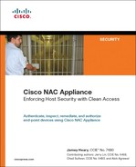
The base installation of NAC Appliance Manager includes three default roles: Unauthenticated, Temporary, and Quarantine. These three roles provide a starting framework for your NAC Appliance testing and implementation. When you are ready to begin deeper configuration of NAC roles and policies, you will most likely need to create custom roles to provide the top-level role groupings for application of various configuration parameters and policies.
To configure a custom role, you must first log in to the NAC Appliance Manager as an administrator. Then complete the following steps:
Step 1. Select User Roles from the navigation options on the left of the screen.
Step 2. Select New Role from the newly presented top navigation bar, as shown in Figure 8-1.
Figure 8-1. New Role Option on the User Roles User Management Screen
Step 3. Configure a role named "Test Role" with a simple description, as shown in Figure 8-2.
Figure 8-2. Custom Role Configuration Screen

Step 4. Verify that the role type is Normal Login Role.
Step 5. Click the Create Role button, also displayed in Figure 8-2.
In addition to the required fundamental steps in the preceding list, several other configuration options are available on the role configuration page displayed in Figure 8-2. Those options are as follows:
- Disable This Role If this check box is enabled, this role will be unavailable for use. It can be re-enabled by clearing the check box and saving the changes.
- Role Name A text field that contains the name of the role as displayed throughout the other configuration pages as a selectable role.
- Role Description A text field that contains a description of this role and its purpose.
- Role Type This selection box contains the options Normal Login Role and Quarantine Role:
— Normal Login Role This is assigned after successful authentication occurs. This role requires that all scans and Clean Access Agent requirements have been met successfully.
— Quarantine Role This role is assigned when NAC Appliance Network Scanning finds a vulnerability on the system. You will need to create an additional role of this type only if the default Quarantine role alone is not sufficient for your specific deployment.
- VPN Policy This option is no longer recommended. If configured, this option makes the use of IPsec, Layer Two Tunnel Protocol (L2TP), and Point-to-Point Tunneling Protocol (PPTP) encryption by the client: Deny, Option, or Enforced (Allowed).
- Dynamic IPsec Key This option is no longer recommended. However, if enabled, the system provides users with a one-time key for their IPsec client after they successfully log in.
- Max Sessions per User Account—This option allows you to limit the number of concurrent sessions for which these user credentials can be used, from 1 to 255 or unlimited. You can also select the Case-Insensitive check box in order to not differentiate case-sensitive names in the session count (for example, JohnUser, Johnuser, johnuser, JOHNUSER could all be considered part of the same session count or separate session counts).
- Retag Trusted-Side Egress Traffic with VLAN (In-Band) If you configure this text box with a VLAN ID, the VLAN will retag the traffic exiting the NAS on the trusted side.
- Out-of-Band User Role VLAN—For out-of-band deployments, this option allows you to set the trusted-side VLAN ID or VLAN name after authentication and assessment.
- After Successful Login Redirect To You can configure a page for the user to be redirected after successful authentication:
— Previously Requested URL—Send the user to the URL originally requested
— This URL—Send the user to the page you define for users in this role in the form of http://url_here
- Redirect Blocked Requests To If a Block IP traffic policy blocks the user, this option sets the location the user is redirected to rather than the blocked address:
— Default Access Blocked Page—Send the user to the default blocked access page
— This URL or HTML Message—Send the user to the page you define for users in this role, in the form of http://url_here
- Roam Policy You can set whether this role allows IPsec, L2TP, and PPTP roaming. This feature is no longer recommended and has been deprecated.
- Show Logged-On Users If the user using this role is a web user, this option allows you to define which information is presented to the user on the logout page, such as IPsec Info (key), PPP Info, User Info, and Logout Button.
Depending on the type of role you are creating, you will utilize various settings on the role configuration page. When the role is created, you can use it throughout the NAC Appliance as well as edit it if required.
Editing or Deleting a Custom Role
After a role is created, you are allowed to return to the role configuration page to edit the role as necessary. In the User Management section of the user roles page, you will see a list of available roles for your deployment, which includes the default and custom roles configured. Next to each role name are several options and icons. Selecting the icon in the Edit column corresponding to the role you want to modify returns you to the role configuration page.
In addition, should you want to remove a role, you can select the corresponding icon in the Del column of the user roles listing page.
Note
Any user configured for a role that has been deleted will not be able to access the network. However, after the role is deleted, all current user sessions will remain active. To clear these sessions and allow the user to reconnect using another active role, you must use the Kick User option on the view online users page.
Configuring Role Assignment
After you have created roles for use in your deployment, you have to appropriately configure role assignment. This can occur in the following ways:
- Create a local user account and assign a role
- Assign by associated VLAN
- Assign by MAC and IP address
- Assign by subnet
- Use external authentication source attributes
Any of these assignment methods can be used to ensure that a user or system is appropriately placed into the correct role.
Creating a Local User and Assigning a Role
You have the ability to create local user accounts on the NAC Appliance Manager when necessary. It is not the recommended user-store and should typically be used only during testing and for guest accounts due to scale and other factors, such as local users' inability to change their passwords.
To create a local user and assign a role, perform the following steps:
Step 1. Select Local Users from the navigation options on the left of the screen located under the User Management section.
Step 2. Select New Local User from the newly presented top navigation bar shown in Figure 8-3.
Figure 8-3. New Local User Option on the Local Users User Management Screen

Step 3. Provide a username for this user.
Step 4. Provide and confirm a password.
Step 5. Provide a description for the user account.
Step 6. Select the appropriate available role from the drop-down box.
Step 7. Verify that all fields are correctly configured as in Figure 8-4, and then click the Create User button.
Figure 8-4. Local User Configuration Screen and Role Assignment

When the previous steps are completed, you will be returned to the Local Users listing page. You should see the newly created account listed there among any other accounts that reside locally. As with roles, you can edit or delete this account by selecting the associated icons on the listing page.
Assigning a Role by VLAN
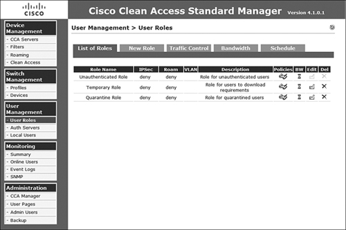
When attempting to assign a user role, another option is to utilize the user VLAN ID. To create this sort of mapping, you are required to utilize an external authentication server. After you select the authentication server for which you want to add the VLAN ID-to-role mapping, you must select the appropriate Mapping icon associated with that authentication server. The list of authentication servers and the Mapping icon are displayed in Figure 8-5.
Figure 8-5. Authentication Servers and Mapping Icon

After you click the Mapping icon for the provider you selected, use the following steps to configure VLAN ID-to-role mapping:
Step 1. Select the Add Mapping Rule link on the right side of the screen, as displayed in Figure 8-6.
Figure 8-6. Add Mapping Rule Link
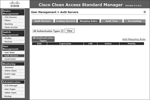
Step 2. On the form that presents itself, verify that Condition Type is set to VLAN ID.
Step 3. To create a matching condition based on VLAN ID, select an Operator of Equals or Belongs To. When using Equals, you are allowed to specify a single VLAN ID (for example, 134). If using Belongs To, you are allowed to enter multiple VLAN IDs separated by commas and, if necessary, include ranges using hyphens (for example, 7, 34, 134, 160-165, 182). For this example, you will use a range as displayed in Figure 8-7.
Figure 8-7. Create VLAN ID Matching Conditions Using the Belongs To Option

Step 4. When configuration is complete, click Add Condition.
Note
It is possible to create a complex mapping that requires the matching of multiple conditions in the list for a full match and role mapping to occur.
Step 5. Verify that your matching condition is added to the list of conditions. You will notice that this condition can be edited or deleted.
Step 6. Now you can complete the role mapping by completing the top portion of the form.
Step 7. Select the role name to which the matching VLAN IDs should be mapped.
Step 8. Select a priority, if necessary. This influences the order in which mapping rules are matched.
Step 9. Enter a description for this mapping condition.
Step 10. Verify the configuration of the role mapping, as displayed in Figure 8-8.
Figure 8-8. Role Mapping Configuration Parameters
Step 11. Click the Add Mapping button.
Note
Mapping rules are processed from the top of the list downward. After a match occurs, the user role is mapped and no further processing of the list occurs.
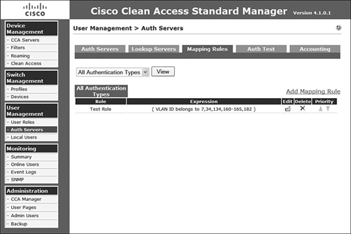
When the previous steps are complete, verify the expression on the mapping rules page. You can create as many mapping rules as necessary. The resulting mapping rule list is displayed in Figure 8-9.
Figure 8-9. Resulting Mapping Rules List
Assigning a Role by MAC and IP Address
Occasionally you will want to define a filter that allows certain MAC addresses and possibly the corresponding IP address to be assigned a user role based on that information alone. This sort of filter can be created at either the global level in NAC Appliance Manager or at the local level in a single NAC Appliance Server. Global policies are automatically distributed to every managed NAS, but if there is a conflicting local policy, the local policy prevails.
To configure a global filter for role assignment in NAM, navigate to Device Management and then select Filters. On the Filters page, follow these steps to create any necessary filters:
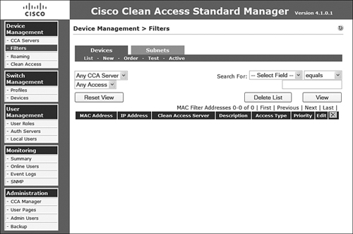
Step 1. On the Device Management > Filters page, as displayed in Figure 8-10, select New under the Devices tab.
Figure 8-10. Filters Menu Options Available on NAM
Step 2. In the MAC Address/IP Address Description (Per Entry) text box, you need to enter each necessary entry or pattern as necessary, placing each one on its own line using the following rules of entry:
— Format each line as MAC/IP DESCRIPTION.
— MAC and DESCRIPTION are required.
— IP is not required.
— Wildcarding of MAC is supported. You can use '*' for a wide match or '-' as a range of MACs.
— The DESCRIPTION field cannot have any spaces.
Step 3. Provide a description in the Description (All Entries) text box.
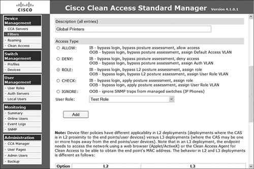
Step 4. Select the access type necessary for role mapping, as follows:
— ROLE Bypasses authentication and assessment and simply provides a role mapping
— CHECK Bypasses authentication but applies posture assessment prior to assigning role mapping
Step 5. Select the appropriate user role you want to map to this filter.
Step 6. Verify the configuration as displayed in Figures 8-11 and 8-12, and then click the Add button.
Figure 8-11. Device Filter Role Mapping Configuration (Part 1)

Figure 8-12. Device Filter Role Mapping Configuration (Part 2)
When configuration is completed, the MAC/IP address combinations from the configuration page display in a table, as shown in Figure 8-13. You can now edit or delete these entries line by line and view the filter list as it is applied at the global level or per NAS by changing the upper-left drop-down select box and clicking the View button. After applying a local mapping on a NAS, you can see the locally configured mapping filter in the list on NAM, as shown in Figure 8-14.
Figure 8-13. Resulting Mapping Rules List
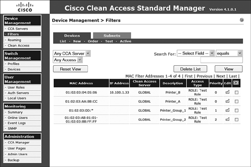
Figure 8-14. Mapping Filter with Local NAS Filter Inserted on NAM View

Note
Configuring a local mapping in NAS uses the same process as in NAM. Simply navigate to the NAS in question and select the Filter tab, Devices, and then New.
Assigning a Role by Subnet
An alternative method to assigning a role by MAC or IP address is to assign it by subnet of the device. On the NAM, under Device Management, select the Filters option and proceed as follows:
Step 1. Select the Subnets tab.
Step 2. Enter the classless interdomain routing block you want to match, such as 10.5.30.0/24.
Step 3. Provide a description.
Step 4. Select Use Role: and then select the role you want to use from the drop-down selection box.
Step 5. Verify the configuration, as in Figure 8-15, and then click the Add button.
Figure 8-15. Configuration of a Subnet Rule Mapping on NAM

The completed configuration places the newly created rule at the bottom of the subnet filter configuration page as displayed in Figure 8-16. As with many of the other options, this option can also be configured at the local level of each NAS. The configuration on the NAS is identical to the process just described and is located on the NAS configuration page under the Filter tab and Subnets option. After configuring them, you can see the list of global and local subnet filters on the Subnet Filter configuration page, as displayed in Figure 8-17.
Figure 8-16. Subnet Rule Mapping Listing Page
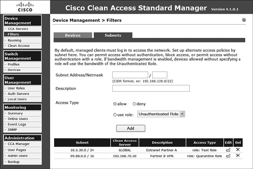
Figure 8-17. Subnet Rule Mapping List Page with Additional Filter from a NAS

Assigning a Role by External Authentication Source Attributes
Although you have covered a few very simple role mapping methods up to this point, the most complex and comprehensive for role mapping is using an external authentication source's extended attributes. As an example, RADIUS provides to NAM some extremely detailed attributes that you can use for granular role assignment, including NAS IP address and Cisco avpair matching as well as role mapping based on the Lightweight Directory Access Protocol (LDAP). Another example external authenticator is a Cisco VPN for Single Sign-On. Options include but are not limited to Framed_IP_Address, NAS_IP_Address, User_Name, and Framed_Protocol. Configuration of this mapping is identical to VLAN ID mapping covered earlier in this chapter except that you select the Attribute option rather than VLAN ID from the drop-down selection on the appropriate mapping, as displayed in Figure 8-18.
Figure 8-18. Attribute Mapping

Role Mapping Summary
There are several ways to map roles to various pieces of information available to NAS and NAM from the user device and authentication session. It is important that you plan your mapping options according to what you have available in your network so that you can effectively produce the desired outcome.
Configuring Authentication
The previous section briefly touched on creating local users as a means of testing access. This section continues that discussion of authentication to NAC Appliances in relation to administrative accounts and also for users authenticating to external data sources.
Creating Admin Users and Groups
Administrators requiring access to the NAC Appliance configuration and reporting options must be created on the NAC Appliance Manager server. The admin accounts can belong to three default admin groups: Read-Only, Add-Edit, and Full-Control. In addition, you can create custom groups with special permissions as necessary for your environment.
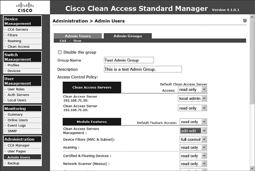
Creating an Admin Group
To create an admin group that more adequately matches your internal support roles in your organization, you will need to open the Admin Users option of the Administration Section on the NAC Appliance Manager. Select the Admin Groups tab and then follow these steps:
Step 1. Under the Admin Groups tab, click New.
Step 2. Provide a group name.
Step 3. Provide a description.
Step 4. Set the default access level for all NAS servers and individual NAS servers. The options for each are Read Only or Local Admin.
Step 5. Set the default and per-module access levels for each module listed.
Step 6. Verify the configuration as shown in Figure 8-19, and then click Create Group at the bottom of the configuration page.
Figure 8-19. Admin Group Configuration
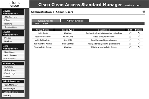
After it is created, the list will be displayed in the admin group list, as shown in Figure 8-20. From there, you can edit and delete other custom groups as necessary. You cannot, however, remove the three default groups.
Figure 8-20. Admin Group List
Creating an Admin User
To allow additional administrators of the NAC deployment to access the necessary systems and reports, they must have an account created on NAM. Navigating to Admin Users in the Administration section presents the admin users page displayed in Figure 8-21. This page presents options to list active sessions, provide a list of administrators, and create new admin accounts.
Figure 8-21. Admin Users List
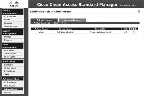
To create an additional admin account, click New and then provide a username, password, description, and admin group assignment. When completed, click the Create Admin button to create the admin user. After it is created, the admin user will be able to authenticate to NAM and appropriate NAS systems and complete all configuration possible as allowed by the admin group membership permission assignments.
Adding External Authentication Sources
Several external authentication servers are supported. The following protocols are supported: Kerberos, RADIUS, Windows NT NTLM, and LDAP. The next section shows how to add a RADIUS authentication server, and the section that follows that gives an example of how to add an LDAP/AD server.
Adding a RADIUS External Authentication Source
To add a new external authentication provider, you must navigate to the Auth Servers menu option under the User Management section. There you will see a list of currently configured authentication providers. Use the following steps to add a RADIUS provider:
Step 1. Under the Auth Servers tab, click New.
Step 2. From the Authentication Type drop-down, select Radius.
Step 3. Enter a provider name that will be advertised to the users as a possible authentication mechanism.
Step 4. Provide the server name where the RADIUS server resides.
Step 5. Enter the server port to be used for RADIUS communication.
Step 6. Select the RADIUS type.
Step 7. Enter the timeout in seconds for RADIUS authentications.
Step 8. Enter the default role for anyone using this provider.
Step 9. Enter the RADIUS server's shared secret.
Step 10. Enter the NAS identifier or NAS IP address.
Step 11. Enter the NAS port and NAS port type if necessary.
Step 12. If you are using RADIUS failover, select the Enable Failover check box and then provide the failover peer IP.
Step 13. If you need to accept empty attributes, you have to select the final check box.
Step 14. Provide a description.
Step 15. Verify that the configuration is accurate, as in Figure 8-22, and then click Add Server to complete the configuration.
Figure 8-22. Configuration of a RADIUS Authentication Provider

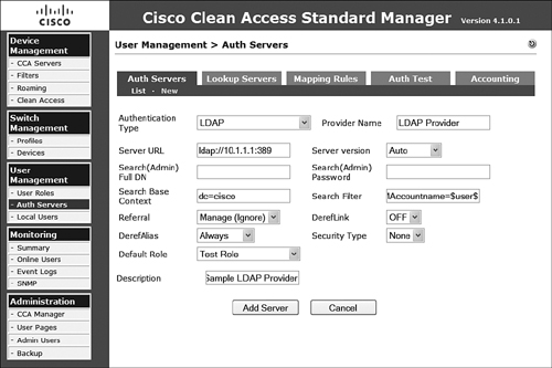
Adding an LDAP/AD External Authentication Source
To add an external authentication mechanism for LDAP/AD, you should select LDAP for the authentication type as the following steps illustrate:
Step 1. Under the Auth Servers tab, click New.
Step 2. In the Authentication Type drop-down, select LDAP.
Step 3. Enter a provider name that will be advertised to the users as a possible authentication mechanism.
Step 4. Enter the server URL in the form of ldap://url.
Step 5. Select a server version from the Server Version drop-down list, which provides the following options: Auto, Version 2, and Version 3.
Step 6. Enter the LDAP Admin ID (Full DN) if the LDAP directory is secured.
Step 7. Enter the associated admin password if the LDAP directory is secured.
Step 8. Enter the search base context in LDAP for searching for the user accounts.
Step 9. Enter a search filter that will match only user accounts. Both UID and SAMACCOUNTNAME are common, but verify with your particular deployment.
Step 10. Select the appropriate referral option.
Step 11. Select the appropriate option for DerefLink to possibly dereference object aliases if they are returned.
Step 12. Select the appropriate option for DerefAlias.
Step 13. Select None or SSL from the Security Type drop-down list.
Step 14. Select the default role to be assigned to any user authenticating using the authentication provider.
Step 15. Provide a description.
Step 16. Verify that the configuration is accurate, as in Figure 8-23, and then click Add Server to complete the configuration.
Figure 8-23. Configuration of an LDAP/AD Authentication Provider
When the configuration of a provider is complete, you can begin to provide role mapping based on the information the authentication provider returns. To see the list of configured authentication providers, simply navigate to the auth servers list page displayed in Figure 8-24.
Figure 8-24. Auth Server List Page

Configuring and Creating Traffic Policies
After a system is authenticated and posture assessed, it will quite possibly be allowed on the network. Based on the results of the authenticated users or systems role assignment and the current status or ultimate outcome of the assessment of the system, it is very likely that the administrator will want to enforce some sort of IP access policy to limit the system's view of the trusted networks behind the local NAS. To accomplish this, you can use a combination of IP-based policies, host-based policies, and bandwidth policies.
Note
The Real IP Gateway mode of NAC Appliance Server will pass only IPv4 traffic (IPv6 in an upcoming release of software); all other traffic types will be blocked. Systems Network Architecture traffic forwarding will be added in a future release.
Virtual Gateway mode can be used for passing other protocols, such as IPX.
Although each of these control mechanisms can be configured on the NAM as a global scope, each can also be configured on each NAS as part of a local scope. For brevity, you will configure only global policies in the following sections of this chapter.
Note
By default, all access from the trusted network to the untrusted network is allowed, whereas all untrusted-to-trusted network traffic is denied. Policies in either direction can be applied per role outside of the default configurations.
IP-Based Traffic Control Policy
IP-based traffic control policies take into account the following information: ports, protocol, and IP addressing. To see a list of currently configured IP-based traffic control policies by role, navigate to User Roles, and then Traffic Control, and finally select IP from the subtab.
Note
IP-based traffic control policies do not perform stateful inspection. The IP policies are stateless in nature—very similar to an access control list on a Cisco IOS router.
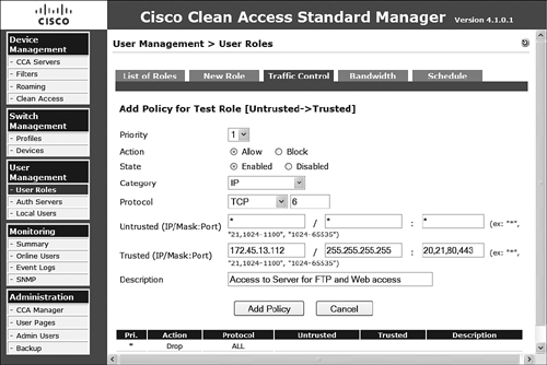
Follow the remaining steps to configure a sample IP-based policy:
Step 1. Next to the appropriate role, select Add Policy.
Step 2. Set the priority of this policy. The lower the number, the sooner it is evaluated against the rest of the multiline resulting policy.
Step 3. Select Allow or Block as the action type.
Step 4. Select Enabled or Disabled to enforce or prevent enforcement of this rule.
Step 5. Select a category of All Traffic, IP, or IP Fragment. By default, the NAS prevents IP fragments to prevent certain denial of service attacks. So, if they are needed, you will have to create an allow policy for them to traverse NAS. If you select IP here, you are presented with more granular form response requirements relating to the protocol and IP information.
Step 6. Select the protocol and protocol number. Options are Custom, TCP, UDP, ICMP, ESP, and AH.
Step 7. Enter the untrusted (IP/Mask:Port) fields, which can be wildcarded as necessary.
Step 8. Enter the trusted (IP/Mask:Port) fields, which can be wildcarded as necessary.
Step 9. Provide a description.
Step 10. After you verify the configuration as correct, as in Figure 8-25, click Add Policy to complete the configuration.
Figure 8-25. Configuration of an IP-Based Policy
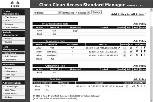
After you add all the necessary IP-based policies required for a particular role, you can view the policy list on the traffic control IP page, as displayed in Figure 8-26. This page also allows you to reprioritize, delete, edit, and enable and disable per rule as necessary.
Figure 8-26. IP-Based Traffic Control Policy per Role Listing Page
Host-Based Traffic Control Policy
Host-based traffic control policies take into account Domain Name System (DNS) name information when allowing or preventing access. This type of policy allows you to configure access to a particular destination DNS name, which could be resolved to a number of IP addresses if the system happens to be load balanced. This feature is also very helpful for controlling access to DNS-resolved hosts that might have many returned IP addresses or that change over time, such as http://www.windowsupdate.com. Additionally, you can allow access to a partial match of the hostname, which will allow access to an entire domain or parts of the domain by name alone. Prior to adding host-based policies for a given role, you should configure the trusted DNS server for that role. This permits only responses from that trusted server to be allowed via this host-based policy. The following steps will configure a sample host-based policy:
Step 1. On the traffic control host page, navigate to the role you want to configure or select the role from the drop-down list, and click the Select button.
Step 2. Enter an allowed hostname or partial hostname, such as cisco.com.
Step 3. Select the matching parameter for this host from the following options: Equals, Ends, Begins, or Contains.
Step 4. Provide a description.
Step 5. Enable or disable the rule.
Step 6. After verifying it as correct, as in Figure 8-27, click Add to complete the configuration.
Figure 8-27. Configuration of a Host-Based Policy

After you add all the necessary host-based policies required for a particular role, you can view the policy list on the traffic control host page, as displayed in Figure 8-28. This page also allows you to delete, add, and enable and disable per rule as necessary.
Figure 8-28. Host-Based Traffic Control Policy per Role Listing Page

Bandwidth Policies
In addition to limiting access by IP addressing, related information, and hostname resolution, you can limit the number of bandwidth systems in a given role. After selecting the Bandwidth tab on the User Roles page, you can select the Edit icon next to the corresponding role for which you want to control bandwidth. Selecting the Edit icon presents the bandwidth configuration form for that role. You can control the following options, which are shown in Figure 8-29:
- Upstream Bandwidth Amount of bandwidth in kbps. Using –1 provides unlimited bandwidth.
- Downstream Bandwidth Amount of bandwidth in kbps. Using –1 provides unlimited bandwidth.
- Burstable Traffic A multiplier from 1 to 10. Multiplying this number by the bandwidth determines the burst traffic.
- Shared Mode Select whether this is for all users in the role or per user.
- Description Provide a description for the bandwidth policy.
Figure 8-29. Configuration of a Bandwidth Policy

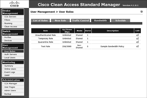
On completion of the configuration steps, the newly created policy will be listed, as displayed in Figure 8-30, among the other bandwidth policies. It is important to note that, by default, NAS does not have bandwidth controls enabled. So, even if a policy is configured on NAM, it will not be enforced until it is enabled on the appropriate NAS.
Figure 8-30. Viewing the Currently Defined Bandwidth Policies
Customizing User Pages and Guest Access
The web page that users see when they are redirected to the NAS web login authentication page is fully customizable. The customization can be a complete rewrite or require only simple editing via the form-based tool provided on the configuration pages. These user pages can also include a guest access option that is relatively simple to configure. If the guest access option is too difficult to manage or not granular enough from a user-tracking perspective, Cisco has provided a web API that allows you to introduce your own scripts capable of creating guest user accounts as necessary.
Login Pages
Configuring and customizing the login pages is a simple process. To start this process, navigate to User Pages from the Administration section. There the Login Page tab displays a list of available login pages. Following the next several steps will allow you to customize your own distinct login page.
Step 1. On the Login Page tab of the User Pages menu, click Add.
Step 2. Specify the VLAN ID and the subnet information as necessary to ensure systems on the specified networks will receive this particular login page.
Step 3. Select a specific operating system, if necessary. OS determination is derived from the HTTP GET request, which pulls the login page from the NAS.
Step 4. After you verify it as correct, click Add to complete the initial configuration.
Step 5. You may now reorder the login pages to ensure that your page will be delivered by using the Move option.
Step 6. When you are ready to continue with the customization, click the associated Edit icon.
Step 7. Select Page Type from the following: Frameless, Frame-Based, and Small-Screen Frameless. The Frame-Based page type allows you to add your own logo and other custom content to the page.
Step 8. Provide a description.
Step 9. Select the web-client method from the drop-down list.
Step 10. Select the configuration check boxes as necessary. These allow for detecting the MAC address and OS as well as renewing IP addresses when necessary.
Step 11. Verify the General Login Page configuration as displayed in Figure 8-31, and then click Update to save the changes.
Figure 8-31. Login Page General Tab Configuration

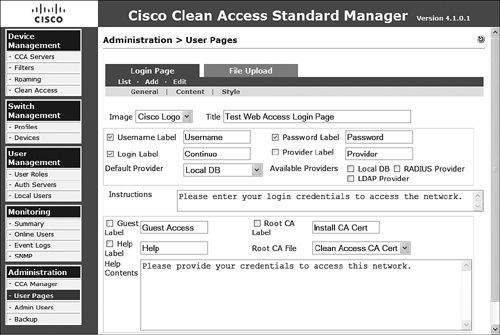
Step 12. Select the Content tab.
Step 13. Select the title as well as the image to display on the login page. Images can be uploaded from the File Upload tab.
Step 14. Provide labels for username, password, login, and provider. In addition, select which options are to display.
Step 15. Select the default authentication provider.
Step 16. Select the available providers.
Step 17. Enter simple instructions for the user in the form of a text string.
Step 18. Enable or disable guest access.
Step 19. Allow or do not allow the user to install the certificate authority (CA) certificate.
Step 20. Allow or do not allow the user to access the help section.
Step 21. Define the CA certificate to present to the user from the drop-down list.
Step 22. Provide the help section test instructions.
Step 23. Verify the configuration, as in Figure 8-32, and then click Update to save the configuration to this point.
Figure 8-32. Login Page Content Tab Configuration
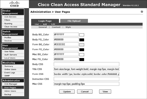
Step 24. Select the Style tab.
Step 25. Configure the various color options.
Step 26. Configure the various style-sheet options (Cascading Style Sheets) if necessary.
Step 27. Verify the configuration as displayed in Figure 8-33, and then click Update to complete the configuration.
Figure 8-33. Login Page Style Tab Configuration
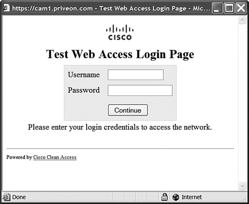
Step 28. After completing the configuration, you can select the View option at the bottom of the configuration pages to see how your changes have affected the login page. This page is shown in Figure 8-34.
Figure 8-34. Completed Customized Login Page
In addition to the previous customization steps, if you had selected frame-based pages, you could continue to configure the content for the right frame, which is blank until configured. Selecting the right-frame option allows you to copy-paste or manually enter the HTML for this frame. You could also enter a properly formatted URL (http://url or https://nam_ip_address/upload/file_name.htm if the file has been uploaded rather than hosted externally). If you are hosting a file externally for this frame, you must ensure that the file is reachable by the host using IP- or host-based traffic control policies. If the URL rather than the IP is being referenced, the URL or IP must be allowed in the Unauthenticated role for the access to be successful.
Guest Access
Enabling guest access to the network can be a simple task. At installation, a guest account was created with a password of 'guest'. Using the skills acquired throughout this chapter, you can provide a guest account access by proceeding through the following high-level tasks:
Step 1. Add a new guest role for the guest account.
Step 2. Associate the guest user account to the guest role.
Step 3. Configure limiting traffic and bandwidth policies for the guest role.
Step 4. Enable the Guest Access button on the login page.
Completing these simple tasks will enable guest access to your network very quickly and securely.
API for Guest Access
Cisco has additionally provided a web-based API that supports Secure Sockets Layer–based POST requests to complete certain tasks. In relation to guest access, this API can be used to create specific user accounts that are applied to a role that is granted only guest access as well as deleting guest access users. The web API is accessible via the NAM at https://nam_address/admin/cisco_api.jsp.
When using the API for configuring guest accounts and when writing API access scripts, it is recommended that you refer to the current API guide and sample code at Cisco.com and in the NAC Appliance Manager documentation. Because the Cisco Technical Assistance Center does not support or troubleshoot user scripts, it is important that you work with a developer familiar with accessing web-based API functions.
Summary
Understanding how to effectively configure authentication mechanisms, user roles, and traffic policies is a requirement for any NAC Appliance deployment. All the functionality presented in this chapter should be well planned in advance, and all preparation possible should be taken. Your deployment will be much smoother when the pre-planning related to IP- and host-based access, guest access, login page configuration, and role assignment is closely tied to your implementation goals.