Cisco IP Telephony Solutions
Cisco offers numerous IP Telephony solutions that scale from the smallest of SMBs through large enterprises and ISP/carrier environments. Each solution is composed of the following high-level elements:
A call processing application (CallManager or its variant, such as CallManager Express [CME], for example)
A hardware platform that supports the call processing application, which can assume the form of one of the following:
- A modular chassis with multiple specialized cards
- A rack-mountable or a tower-based server
- A router/gateway
Voice applications that, as a function of capacity, might either require their own dedicated hardware platforms or be able to coexist on the same platform as the call processing agent
IP phones (a wide-ranging selection is available)
Legacy telephony integration platforms in the form of one of the following:
- Standalone dedicated gateways
- Cards for modular solutions
Integrated IP Telephony solutions include all or a subset of the preceding elements, with each solution straddling a spectrum of scalability in terms of features and capacity. To match a customer's IP Telephony requirements with the capabilities of a solution, it is recommended that you proceed as follows:
Choose the applicable high-level elements for a candidate solution from the preceding list.
Drill down the high-level solution elements to come up with the specific solution components as a function of the following:
The required level of scalability and performance
The specific hardware platforms
The desired topology
The required configuration expertise to deploy the solution
For the purpose of designing an SMB IP Telephony solution using Cisco products, consider the following building blocks, which incorporate the high-level IP Telephony elements along with issues related to configuration and topology:
Integrated IP Telephony solutions
CallManager deployment options
CallManager integration with legacy PBX
CallManager dial plan configuration considerations
IP Telephony voice applications
Cisco IP Phones
Cisco ISP/carrier solution
Integrated IP Telephony Solutions
Integrated IP Telephony solutions provide a foundational set of hardware, software, and features that allow a designer to tailor the solution to the specific customer requirements. In effect, Cisco does part of the design through its integrated product offering, and the detailed customization becomes the designer's responsibility. The following integrated solutions are considered:
CME solution
MCS 7800 series solutions
ICS 7750 solution
CME Solution
CME is an IOS-based call processing application (formerly known as IOS Telephony Services) that is intended for small SMBs, with requirements for up to 120 physical phones. CME incorporates the concepts of Ephone (Ethernet phone) and Ephone-dn (Ethernet phone directory number). Ephone and Ephone-dn are software constructs (configurable in IOS) that collectively allow for a greater simultaneous number of calls to be processed than there are physical phones in the system.
The number of Ephones in a CME system corresponds to the number of physical phones, but the number of Ephone-dns can exceed the number of physical instruments by a ratio of anywhere from 2.4:1 to 5:1. In practical terms, through the use of Ephone and Ephone-dn constructs, the same phone instrument can handle more than one call at a time, or the same extension can be shared between multiple instruments. Ephones and Ephone-dn constructs represent a powerful capability for building customizable IP Telephony environments in small SMB scenarios.
Table 8-1 summarizes the characteristics of the CME solution. It should allow you to determine at a glance if the solution is appropriate for a given set of customer requirements. These characteristics are representative as of the time of this writing and should always be verified against the latest data sheets for additions or subtractions.
| Characteristic | Values |
|---|---|
| Platform | IAD[*] 2430, 1760s, 2600s, 3600s, 3700s |
| IP phone capacity | Up to 120 IP phones as a function of platform |
| IP phone support | 7902, 7910, 7912G, wireless IP 7920, conference station 7935 and 7536, 7940G and 7960G as a function of platform, IOS version, and firmware version |
| Ephone-dn | Up to 288 as a function of platform. Platforms that support a larger number of IP phones also support a larger number of Ephone-dns. |
| Compatibility and integration | CallManager, Unity, Unity Express[**], Microsoft CRM |
| Deployment model | CME LAN or via a provider. Not intended for deployments over a WAN. |
| Features | Transfer, hold, distinctive ringing, on-hold pickup, intercom, paging, music on hold (MOH), night services, do not disturb, and many more |
[*] IAD = Integrated Access Device.
[**] Unity Express is a scaled-down version of Cisco Unity, which is discussed in Chapter 9.
For smaller SMBs (up to 100 users), the higher-end IP Telephony solutions that scale significantly past the current number of users' requirements always remain a design option. That's especially true if an SMB anticipates significant growth, its budget accommodates the higher-end solution's cost, and the entry-level solution's features are deemed insufficient. However, the CME solution, with its numerous features and integration capabilities (including Microsoft's CRM), represent a serious contender for the smaller-size SMB market.
MCS 7800 Series Solutions
The Cisco MCS 7800 series represents a family of IP Telephony solutions that are capable of meeting the telephony requirements of SMBs and enterprise alike. Nine MCS models are available as of the time of this writing, with several more models having reached the end of the sale cycle.
CallManager remains at the core of the MCS series, whereas hardware platforms (tower-based and rack-mountable servers) that offer a wide range of performance and storage capacity options make these solutions scale from 200 to thousands of phones. The three MCS models that are most applicable for SMB environments are MCS 7815-1000, MCS 7815I-2000, and MCS 7825H-3000. Their collective characteristics are summarized in Table 8-2.
| Characteristic | Values |
|---|---|
| Models | MCS 7815-1000, MCS 7815I-2000, MCS 7825H-3000. |
| Hardware platforms | Tower-based and rack-mountable with Celeron and Pentium 4 processors (1 GHz to 3.06 GHz). |
| IP phone capacity | From 200 to 1000, with up to 4000 with CallManager clustering. |
| IP phone support | All models of Cisco IP phones as a function of requirements. (See the “Cisco IP Phones” section later in this chapter.) |
| Application support | Unity, Unity Bridge, Cisco Conference Connection, Cisco IP Interactive Voice Response (IVR), Cisco IP Contact Center (IPCC) Express, Cisco Queue Manager. |
| Deployment models | As applicable to CallManager. (See “CallManager Deployment Options” later in this chapter.) |
| Features | As applicable to CallManager, which is the call processing application for all of the MCS 7800 series models. Given the CallManager's extensive features, you should refer directly to the CallManager specifications on the Cisco website. To determine the feature set for the integrated solution, combine the CallManager features with those of all of the relevant applications. |
| Integration with legacy telephony (PBX, PSTN) | Via gateways and multiservice routers. |
For the larger-size SMB IP Telephony deployments that cannot be accommodated by CME, the offerings of the MCS 7800 series solutions (as detailed in Table 8-2) can be summed up as follows:
The different MCS models of varying processing speed and capacity provide significant granularity in the number of supported users and voice applications
CallManager provides the core telephony functionality and integration capabilities with legacy telephony installations
ICS 7750 Solution
The Cisco ICS 7750 is another integrated IP Telephony solution that scales the spectrum of SMB sizes and branch offices of larger enterprises. Physically, ICS 7750 is a multislot, industry-grade chassis system that accepts cards offering a wide range of voice connectivity and applications options.
NOTE
Cisco has discontinued the shipment of ICS 7750, but the product continues to be available through secondary markets, and the Cisco Technical Assistance Center (TAC) will continue ICS 7750 support through 2009. The ICS 7750 modular architecture readily lends itself to examples of design principles.
The capabilities of the ICS processor cards allow it to replace and/or integrate with an existing PBX system, integrate with PSTN or an H.323 network, and permit the continued use of analog telephony instruments within the SMB or enterprise networks. The ICS processor cards fall into the following categories:
Multiservice routers and voice gateways or Multiservice Route Processor (MRP) cards— These cards facilitate ICS integration with H.323 networks, PSTN, and analog phone instruments within the SMB or enterprise networks. Physically, MRPs come with either one or two slots that accept more than a dozen different interface cards, including voice interface cards (VICs), WAN interface cards (WICs), and voice/WAN interface cards (VWICs). The VIC/WIC/VWIC support offers you a wide range of physical layer voice/WAN interface choices. ICS 7750 supports up to five MRPs. MRPs also offer the typical IOS services (VPN, VLAN routing, and firewalling) for integration with data networks.
Application servers or the System Processing Engine (SPE) cards— These cards are full-blown computers that support a high-speed Pentium processor, onboard memory, hard drives, universal serial bus (USB) ports, a monitor port, and a mouse/keyboard port. They run CallManager, System Manager for web-based configuration and management, and a range of voice applications, including Cisco Unity Voice Messaging, IP IVR and Integrated Contact Distribution (ICD). The SPE310 is an example of an application server card. At least one SPE is required in an ICS 7750. Up to five SPEs are supported for redundancy, greater scalability, and processing power. SPEs are hot-swappable.
Ethernet switch or the System Switch Processor (SSP) card— This is an IOS-based Ethernet switch that provides an interface between any of the other cards (MRPs, SPEs) residing within the ICS chassis and the Catalyst switches that connect to it. Catalyst switches aggregate the communication endpoints (Cisco IP phones or the IP SoftPhones) that are part of the ICS 7750 solution. ICS 7750 requires one SSP to reside in a specific slot.
Hardware monitor or the System Alarm Processor (SAP) card— The function of this card is to integrate with the System Manager software (which resides on the SPE) by sending it the relevant system monitoring or fault detection information. At least one SAP card is required in an ICS chassis in a specific slot.
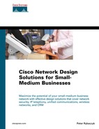
An absolute minimum ICS 7750 configuration includes a single SPE, an SSP, and a SAP card. The designer has the choice of complementing that configuration with additional SPEs and MRPs. However, with that minimal configuration (assuming a single site deployment model and no voice gateways present elsewhere on the network), calls cannot be made outside the SMB's network. To make the minimal solution more practical, an MRP card is required. An MRP card integrates the ICS 7750 with either an IP WAN or PSTN for calls outside of the network. Figure 8-2 graphically represents the functionalities and capabilities of the ICS 7750.
Figure 8-2. ICS 7750 Functionalities and Capabilities

CallManager Deployment Options
The CallManager accommodates single-site or multisite topologies, deploys standalone or in clusters, and scales for up to 10,000 users when installed in a cluster on the largest supported server platform. An IP Telephony application that supports up to 10,000 users readily exceeds the typical SMB requirements, but it also reflects that the application is scalable from SMBs through large enterprises as a function of hardware platform and configuration.
In the case of MCS 7825H-3000, a single CallManager accommodates more than the typical SMB requirement of up to 1000 users. On the ICS 7750, a single CallManager accommodates up to 500 users, but if a cluster of CallManagers is needed, it can consist either of SPEs in distinct 7750 chassis or SPEs in the same chassis.
The combined elements of topology, clustering, and PSTN/IP WAN integration on the CallManager platforms yield the following generic CallManager deployment scenarios:
A single-site deployment with a single CallManager or a cluster
A distributed multisite deployment with a single CallManager or a cluster at each site and PSTN between the sites
A distributed multisite deployment with a single CallManager or a cluster at each site and an IP WAN between the sites
A centralized multisite deployment with a single CallManager or a cluster at only one site and an IP WAN between the sites
Single-Site CallManager Deployment
A single-site deployment, with an interface to PSTN for outside calls, is the simplest of all of the deployment models and can be used as a building block for more complex designs. This model involves either a single CallManager or a cluster (for redundancy and/or greater scalability). For the MCS 7800 solutions, clustering involves multiple servers. In the case of the ICS 7750 solution, clustering can be accommodated through multiple SPEs in the same chassis.
As an example, consider the components of a typical ICS 7750 redundant configuration for a single-site deployment. These components can be mapped to corresponding hardware in any of the CallManager-based solutions:
An MRP300 with a multiflex trunk voice/WAN interface card. The VWIC (VWIC-1MTF-T1, for example) would provide a digital interface to a PSTN of 24 DS0 channels. Other options, as a function of having to accommodate analog phone instruments or having an interface to an existing PBX, might include an MRP with Foreign Exchange Station (FXS) ports (for analog instruments), or Foreign Exchange Office (FXO) ports (for interface to a PBX).
Two SPE310 cards, each with CallManager for redundancy and additional voice applications (IVR, ICD, Unity Voice Messaging, Unity Unified Messaging, for example). USB ports on the SPE300 would allow for the connection of external backup devices to ensure proper backups of the applications, data, and configuration files.
The required SSP and SAP cards. The SSP provides an interface to the LAN (Catalyst switches) that is used for the IP phones. The SAP interacts with the System Manager residing on the SPE.
An appropriate number of IP phones plugging into the Catalyst switches that are interfaced to the SSP.
A robust single-site design should include power protection for the CallManager platform via an uninterruptible power supply (UPS) and for the Catalysts (aggregating IP phones) via the Cisco Redundant Power System (RPS) 300. The Catalyst that was specifically developed for use with the CallManager-based solutions is the 3524-PWR XL, but the solutions also work with the 4000 and 6500 series switches. The 3524-PWR XL supports 24 10/100 ports with inline power, 2 GBIC-based Gigabit Ethernet ports, and a redundant power connector that can be used by the RPS 300.
Distributed Multisite CallManager Deployment with PSTN
A distributed multisite deployment, with PSTN for calls between the sites and outside the network, duplicates at multiple locations the single site with PSTN design. This deployment assumes that even if there is IP connectivity between the sites, it is not sufficient to support voice traffic. IP connectivity might be adequate to meet data transmission requirements.
Assume that the problem with IP connectivity is either too high a cost for sufficient bandwidth to support voice or poor availability of WAN services. There is still value to deploying CallManager on a corresponding platform at each site as part of a longer-term strategy to have a more fully integrated voice/data network.
For the ICS 7750, the MRP cards with their WIC support are capable of a wide range of IP connectivity options. This means that even if voice traffic is not flowing over the IP WAN, the IP WAN can be established without additional routing equipment. Given the flexibility in WAN connectivity that is afforded by the WICs, two future options for greater integration are possible:
First, the cost of the existing WAN service would go down over time, which could allow the SMB to provide higher bandwidth and to start passing voice traffic over the WAN.
Second, a new higher-bandwidth WAN service could become available at a reasonable cost. Assuming the availability of a compatible WIC for that service, a WIC swap and an addition of a gatekeeper might be all that is needed to support the voice/data integration on the WAN.
Naturally, there should be some economic justification for the voice/data integration over the WAN. The financial justification could come from lower costs resulting from reducing PSTN connectivity at each site (if not eliminating it completely at some sites) and from toll savings for long-distance calls between the sites.
Distributed Multisite CallManager Deployment with IP WAN
A distributed multisite CallManager deployment, with an IP WAN that interconnects all of the sites, offers you the option of using the IP WAN for voice traffic between the sites or continuing to rely on PSTN for intersite calls. The assumption here is that IP WAN will be used for intersite voice traffic.
A major design consideration in this deployment model is to determine whether the intersite bandwidth is sufficient to carry the estimated amount of voice traffic, especially if the WAN needs to be shared with data traffic. Bandwidth consumption for voice traffic is a function of the type codec that is configured on IP phones.
Cisco IP phones support G.711 and G.729a codecs, the characteristics of which are shown in Table 8-3.
| Codec | MOS | Compression Delay | Bit Rate |
|---|---|---|---|
| G.711 | 4.1 | 0.75 ms | 64 Kbps (about 80 Kbps of bandwidth per call when the entire overhead associated with a call is included) |
| G.729a | 3.92 | 10 ms | 8 Kbps (about 14 Kbps of bandwidth usage) |
The difference in MOS and compression delay between the two codecs is sufficiently small (remember that up to 250 ms round-trip delay is acceptable for voice calls). If bandwidth is at a premium, the codec that results in the smaller bandwidth consumption should be deployed. If bandwidth is not an issue, consider using the codec with the smallest compression delay and the highest MOS. Also, keep in mind that codec support is not static; it continues to evolve as a function of time and equipment enhancements.
A distributed multisite deployment implies that each site has its own CallManager (call processing agent), which is at the core of integrated solutions like the MCS 7800 series and ICS 7750. A call processing agent can also be a legacy PBX with a VoIP gateway or a Cisco IOS Telephony Services (ITS) device. A number of Cisco routers support ITS, which is meant for IP Telephony deployments of up to 48 IP phones. ITS remains viable, but it represents an older solution, which Cisco is replacing with CallManager Express.
The presence of a call processing agent at each site means that call control traffic is not carried over the WAN because it transpires between the call agent and the endpoint at each site. An additional element in this model is a dedicated gatekeeper. The gatekeeper's function is to provide call admission control. If you choose, the gatekeeper can also be used as part of the overall dial plan configuration, which would simplify the dial plan configuration on the individual CallManagers. A multisite distributed model applies in SMB environments, but it also scales for large enterprises.
A distributed multisite deployment would typically use PSTN at each site as a backup for overflow calls (insufficient WAN bandwidth availability to make a call) or in the case of the IP WAN failure. However, the use of PSTN for those functions is a design decision that depends on the user requirements. It's possible that only a single gateway at only one site will be used for all PSTN calls. That could severely limit the external call capability at various sites in the event of even a partial WAN failure.
Several options are available for designing the dial plan in this model. The most scalable option is to use the gatekeeper dial plan, which means that most of the configuration is performed on the gatekeeper, with only minimal configuration required on each CallManager. The complete opposite of the gatekeeper dial plan is the site dial plan, in which no dial plan configuration is performed on the gatekeeper, and the entire configuration is conducted on CallManagers. The site dial plan does not scale well as the number of sites increases because any change to the plan at one site requires changes at all the other sites. With the site dial plan configuration, the gatekeeper function is reduced to admission control.
A compromise dial plan, if necessary, lies in the hybrid approach in which the dial plan configuration is distributed between the gatekeeper and CallManagers. With only two or three sites, the choice of a dial plan is a lot less important than it is with a dozen or more sites. If an SMB anticipates the deployment of more than a few sites, the gatekeeper or hybrid dial plans are preferable as the initial choice. From the implementation and network administration perspective, if you change a dial plan after the initial installation and configuration, you might have to do so at some rather unusual hours.
Because a gatekeeper is of critical importance in the distributed multisite deployment model, you should consider all available redundancy techniques, including the following:
Multiple gatekeepers (to minimize the impact of the failure of a single gatekeeper)
Alternate gatekeepers (which are configured to take over the gatekeeping function when requests from the call processing agent to the primary gatekeeper time out)
HSRP for the pairing of gatekeepers
Aside from any economic benefits resulting from carrying voice traffic over a WAN, the great benefit of the distributed multisite model is its high scalability. Business environments are not static; an SMB can quickly turn into a large enterprise through growth or acquisitions.
Centralized Multisite CallManager Deployment
A centralized multisite deployment assumes that an IP WAN is present between the sites but that only one site is equipped with the CallManager. In this deployment model, the IP WAN carries both the call control and the voice traffic in addition to any data traffic. Similar to the distributed multisite design, call admission control is required in this deployment model to ensure that the WAN links are not oversubscribed by the voice calls. Although the H.323 gatekeeper provides admission control in the distributed model, CallManager can be configured to provide admission control in this model.
The issues of bandwidth capacity and PSTN access in this model need to be considered in a manner similar to the distributed multisite model. The provisioning of WAN bandwidth needs to take into account the calling patterns and the type of codec that will be used for voice compression.
From the service availability perspective, each site should be equipped with a voice gateway supporting the Survivable Remote Site Telephony (SRST) feature, which allows PSTN access even in the event of a site being cut off from the call processing agent due to the WAN failure. With a voice gateway at each site, PSTN calls could also be made when the WAN link cannot carry any more voice calls due to high utilization. H.323-capable gateways afford the capability of making PSTN calls after losing connectivity with the CallManager due to WAN failure.
One of the greatest benefits of the centralized multisite deployment is the relatively simple administration and management of this model as compared to the distributed multisite model. The price, of course, is a more limited scalability in terms of the number of sites that can be supported in this model. Which model you choose depends on the user requirements. You can also view this model as a building block and combine two or more centralized multisite deployments into a distributed multisite deployment where, effectively, each centralized multisite deployment can be logically thought of as a single site component of the multisite distributed model.
CallManager Integration with Legacy PBX
Technically, the installation of CallManager integration with legacy PBX is simple. For example, if the requirement calls for PBX/ICS 7750 integration, choose an MRP card that supports a VIC (VIC-2E/M, for example) to connect the ICS 7750 to a PBX. MRP300 fulfills that requirement.
From a business perspective, however, PBX/CallManager integration has a major implication. If an SMB is wary of the proposed IP Telephony solution and is reluctant to let go of the legacy technology, the SMB does not need to scrap the existing installation before trying IP Telephony.
Integration of CallManager with an existing PBX protects the existing investment while allowing a group of users within the SMB's network to try the new solution before completely switching to IP Telephony. It's the “try before you buy” approach, which shows that IP Telephony solutions designers are not immune to dealing with budgetary constraints and/or end-user psychology.
CallManager Dial Plan Configuration Considerations
Dial plan design is a critical component of any IP Telephony solution deployment. If an IP Telephony solution is going to replace an existing PBX (or multiple PBXes), consider that each PBX has probably been programmed and tweaked over many years. In all likelihood, there is poor documentation regarding the assigned and available internal numbers and classes of service associated with them.
An absolutely exact one-to-one mapping between the PBX programming and the new solution configuration is, perhaps, not necessary. However, it is necessary to determine the following:
User calling patterns
Classes of service (the ability to make international or other toll calls, for example)
The actual E.164 numbers for all of the users (especially if DID is allowed)
Familiarity with the concepts of partitions and calling search spaces, as they are used in the CallManager configuration process, is also recommended.
Partitions and calling search spaces correspond directly to the destination numbers that an end user can dial and the class of service configuration within a PBX. Partitions aggregate destination numbers and their route patterns (a group of numbers within a certain geographical area, for example), whereas calling search spaces determine which partitions an end device (IP phone) can access to make a call. Destination numbers that are dialed by a user but that are not defined in any of the partitions, as determined by the calling search space, receive a busy signal. In other words, they are not reachable.
Use of partitions and calling spaces allows you to define the necessary level of granularity for each user (or a group of users) for all external calls via PSTN. For example, classes of service in the form of unrestricted international calls, international calls to specific countries, or even calls to specific destinations within a given country could be readily defined and associated with the users meeting the criteria for making those kinds of calls.
The dial plan complexity varies as a function of the type of CallManager deployment model. A single-site deployment is the simplest; the dial plan needs to consider only internal calls within the site and external calls through the PSTN gateway. Destination numbers within the site could be abbreviated (extensions), whereas PSTN calls would use the actual E.164 numbers that are applicable in the country where the solution is deployed or the countries that can be called.
A centralized multisite deployment dial plan has similar characteristics to the single-site model, except that voice gateways are now present at each site, and they become part of the dial plan configuration. The typical configuration allows each user at each site to make unrestricted calls within the network and to use the local PSTN gateway for outside calls. In the event of WAN failure, intersite calls are made through the PSTN gateway as well. The dial plan on each gateway should identify the CallManager for intersite calls and PSTN for external calls.
Most choices in developing a dial plan are available in the distributed multisite model, which, as mentioned previously, requires a gatekeeper. However, regardless of the ICS 7750 deployment model, the general approach to developing a dial plan is always the same: It must address how calls are made within a site, between sites, and outside the network. For the distributed multisite model, you can choose the dial plan from the following three options:
The site dial plan calls for leaving the gatekeeper out of the dial plan configuration and configuring each CallManager with the destination numbers of all of the other sites and all possible routes to each site. This plan clearly lacks scalability as the number of sites grows and/or the number of redundant paths between the sites increases. Adding new sites or changing one site requires reconfiguration of all the other sites.
The gatekeeper dial plan centralizes the dial plan configuration on the gatekeeper. The gatekeeper is now responsible for resolving E.164 numbers to IP addresses during the call admission process and for providing for overflow or failover to PSTN. CallManagers at each site require only a minimal configuration.
The hybrid approach allows you to develop a highly customized dial plan that combines elements of the site and gatekeeper plans.
IP Telephony Voice Applications
As stated in Chapter 3, “Network Infrastructure Requirements for Effective Solutions Implementation,” the applications and the value that they bring to the SMB's operations ultimately define a networking solution. It's no different with IP Telephony. If an SMB wants more than just the ability to make phone calls (plus some other basics, such as hold, transfer, speed dial, and so on), IP-enabled voice applications are a key part of CallManager-based and CME solutions.
Consider the capabilities of the following categories of select applications, which are further broken down into individual components:
- Voice Messaging. It facilitates storage and retrieval of voice messages while supporting multiple personal greetings, multilingual prompts, and custom settings for call handling.
- Unified Messaging. It provides an integrated graphic interface to e-mail, voice messages, and faxes.
- Automated Attendant. It is functionally comparable to the CallManager Auto Attendant but is at the individual user level. It acts as a personal electronic receptionist and can manage incoming calls based on DID, DNIS, and caller ID or ANI.
- Visual Messaging Interface. It provides a web-based interface for accessing and managing voice-mail messages.
Customer Response Solution (CRS). The CRS applications require the CRS engine that runs on the SPE, in the case of the ICS 7750.
- IP Interactive Voice Response (IP IVR). It incorporates the Cisco IP Auto Attendant. However, the key difference between the IVR application and the Auto Attendant is that IVR interacts with a database. After a caller enters identifying parameters (for example, password, account number, and PIN number), an IVR application allows for the performing of functions (such as funds transfers and placing of orders) and can also supply callers with information about their account status.
- IP Integrated Contact Distribution (IP ICD). This is an IP-based equivalent of the Automatic Call Distribution feature in the traditional PBXes. It integrates with the IP IVR application and allows for the distribution and answering of calls based on several predetermined methods of real-time agent availability.
Cisco IP Phones
IP Telephony users are not as concerned with the infrastructure component of the solution as with the capabilities of the instruments that are sitting on their desks or in the conference room. Cisco offers several physical instruments, along with the IP SoftPhone, that work with numerous variants of CallManager-based solutions. Table 8-4 summarizes key characteristics and the typical use of select models of the Cisco IP Phones.
All Cisco IP Phones support G.711 and G.729a audio compression (codec). You should refer to the data sheets for each instrument for the full description of all features, protocol support, safety requirements, and physical characteristics, such as weight and size.
Cisco ISP/Carrier Solution
The Cisco ISP/Carrier IP Telephony solution centers on the universal series gateways (AS54xx/AS58xx) and H.323 gatekeepers for creating a nationwide or worldwide IP network to carry voice traffic. Approaches to using the universal series gateways follow. Other approaches might exist or be developed as a function of the IP Telephony designers' creativity and ingenuity.
Analog telephony end users dial in to a gateway, which ties into an IP network.
- Voice traffic is carried over the IP network and terminates at another gateway, if possible, that has IP connectivity with the gateway receiving the call.
- Alternatively, if the termination through another gateway is not possible, the call is terminated via PSTN.
- The gateway operator develops the dial plan that makes this process transparent to the customer.
- The customer's call might or might not go over the IP network, but the customer should not be aware of which way the call is routed.
The universal series gateway is interfaced to a Class 5 switch.
- The gateway accepts TDM traffic from the switch.
- The gateway passes TDM traffic (following its conversion into packets) onto the IP network.
The latter approach comes about most likely because of the lower cost of routing the TDM traffic via the IP network than via the existing TDM network.
Both of the preceding approaches rely on the gateways' operator having a well-developed IP network that reaches into areas where TDM is either not available or is a lot more expensive than delivering voice traffic over IP. As of this writing, the protocol of choice for these kinds of deployments is H.323.
As a function of the number of gateways, you ought to consider deploying gatekeepers to improve the network scalability. The configuration of zones on the gatekeeper can minimize the number of dial peers (VoIP, POTS) that must be configured on the gateways, and thus can facilitate the creation of complex yet scalable dial plans.
The same gatekeeper principles that applied in the preceding scenarios apply to a LAN-based IP Telephony that is using a CallManager-based solution in a distributed multisite deployment model. You can pair gatekeepers via HSRP, configure alternate gatekeepers on each gateway, and break the network down into multiple zones to assist with gatekeeper administration and to minimize the impact of the failure of any single gatekeeper or even a group of gatekeepers. In addition, the H.323 network can further scale through the deployment of a directory gatekeeper, whose function is to manage the zone-level gatekeepers.
AS5450 scales up to 16 CT1/CE1s or a single CT3. A CT3 is equivalent to 28 T1s, resulting in 672 voice ports. AS5850 supports up to 5 CT3s or 96 T1s. The channelized ports are normally used for TDM voice traffic, whereas serial ports interface the gateways to the IP WAN.
All universal series gateways support common and scalable routing protocols, including the Cisco EIGRP, OSPF, IS-IS, Border Gateway Protocol (BGP), and more. Using a scalable routing protocol with fast convergence characteristics is important in any major H.323 deployment that involves multiple gateways and gatekeepers. It greatly improves the IP network stability. In addition to the TDM and WAN ports, each universal series gateway has 10/100 Ethernet interface(s), typically used for LAN access to Authentication, Authorization, and Accounting (AAA) servers like Remote Access Dial-In User Service (RADIUS) or Terminal Access Controller Access Control System Plus (TACACS+).