
CHAPTER 7
Operations, Management, and Orchestration in the Cloud
The first words in the title of this chapter refer to the means of supporting the Operations and Management (OA&M) of the Cloud infrastructure. While the practice of operations and management has been fairly well understood and even partly standardized, the word “orchestration” remains somewhat ambiguous, one of the most misused words in the industry. Yet the concept of orchestration is critical to Cloud Computing. Our first task is to clarify this concept.
Things were simpler in the 19th and 20th centuries,1 when orchestration simply referred to the task, performed by a composer, of writing a score for an ensemble of musical instruments (typically a symphonic orchestra). The same word has also referred to the musical discipline—taught in conservatories as part of a composition curriculum—of writing for orchestra. The discipline catalogs the musical characteristics (range, timbre, technical difficulties, and idioms) of the representatives of various groups of instruments (strings, woodwind, brass, and percussion)—the subject also referred to as instrumentation—and teaches how different individual instruments may be combined or juxtaposed to achieve the sound color and balance envisioned by a composer. It should be noted that the physical characteristics of the instruments employed in the modern symphonic orchestra have been largely standardized, and orchestra performers have been trained according to this standard. That makes the instrumentation part rather precise (in specifying, for example, which trill is easy to play on a trombone, and which one is impossible to play). On the other hand, the orchestration proper—that is, the part that deals with combining the sound qualities of various instruments to achieve new effects—can do nothing more beyond listing a few generic principles and then bringing in various examples from the work of masters to illustrate the effects created. If one follows these examples as rules, one cannot create new effects. Yet, great composers (notably Richard Wagner in the 19th century and Maurice Ravel and Igor Stravinsky in the 20th century) have revolutionized orchestration by discovering new and striking sound combinations that fit their respective artistic visions. Once their music became known and accepted, their scores became a new source for teaching orchestration. We refer interested readers to an excellent book on orchestration [1], from which at least one author has learned much.
The meaning of orchestration in Cloud Computing is not that dissimilar from that of its original counterpart in music. In the Cloud, the “instruments” are the resources described in the previous chapters. The word “instruments” refers to both physical resources (i.e., hosts, storage, and networking devices) and software resources (hypervisors and various operating systems), all of which are “played” with the single purpose of introducing and supporting Cloud services.
Two NIST Cloud architecture publications [2, 3] address this subject with the following definition:
“Service Orchestration refers to the composition of system components to support the Cloud providers' activities in arrangement, coordination and management of computing resources in order to provide Cloud services to Cloud Consumers.”
The NIST Cloud Computing reference architecture [3] illustrates the task of orchestration (depicted here in Figure 7.1).
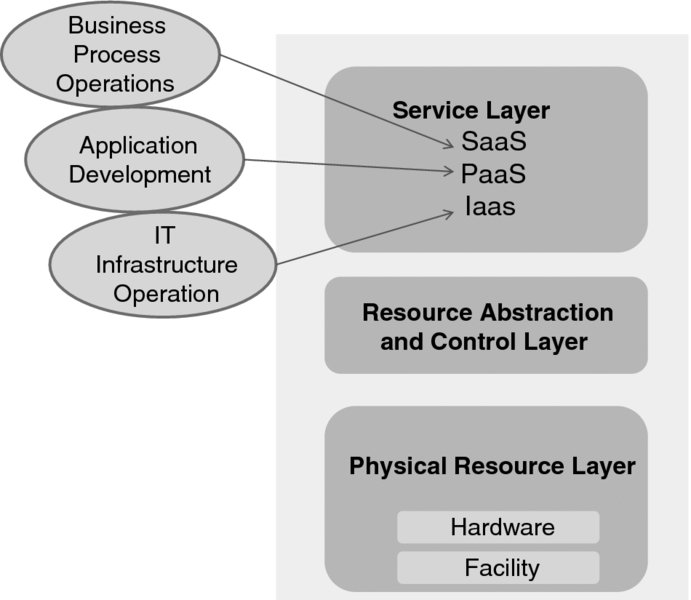
Figure 7.1 Service orchestration (after NIST SP 500-292).
The NIST three-layered model represents the grouping of the components that a Cloud provider deals with. On the top is the service layer where the service-access interfaces are defined. The middle layer contains the system components that provide and manage access to the physical computing resources through software. The control aspect here relates to resource allocation, access control, and monitoring. NIST refers to these as “the software fabric that ties together the numerous underlying physical resources and their software abstractions to enable resource pooling, dynamic allocation, and measured service.” At the bottom of the stack is the physical resource layer, which includes all hardware resources—computers, storage components, and networks, but also “facility resources, such as heating, ventilation and air conditioning (HVAC), power, communications, and other aspects of the physical plant.”
How exactly these resources are coordinated is not specified in [3]; we will provide some “under-the-hood” views later in this chapter. (In particular, we will extend the above model in Section 7.3.) What is important is that the NIST description underlines the distinction between service orchestration and service management tasks performed by a Cloud provider. Service management includes “all of the service-related functions that are necessary for the management and operation of those services required by or proposed to Cloud consumers.” The three service management categories are business support, provisioning and configuration, and portability and interoperability.
In the business support category are the tasks of customer-, contract-, and inventory management, as well as accounting and billing, reporting and auditing, and pricing and rating. The actual operation of the Cloud is the subject of the provisioning and configuration category, whose tasks include provisioning, resource change, monitoring and reporting, metering, and SLA management. Finally, data transfer, VM image migration, and the all-encompassing application and service migration are the tasks of portability and interoperability, accomplished through the unified management interface.
To understand what is actually involved, it is necessary to distinguish the components and observe the respective evolution of each of them separately.
In the first section of this chapter we discuss the evolution of the concept of orchestration in the enterprise (i.e., IT) industry—where the concept was actually born at the turn of the century.
In the second section, we review the discipline of network and operations management, with the emphasis on the evolution of the operations support systems. Note that, the word “network” aside, network management is a purely software matter. Network management is used both in the enterprise and telecommunications industries, but naturally it originated in the telecom world. In the context of this discussion we will also review several widely implemented standards.
The third section of this chapter synthesizes the above concepts in the context of Cloud, where hosted services (along with the appropriate orchestration tools) have been offered to an enterprise by the Cloud provider (who naturally needs its own tools to orchestrate the services). As might be expected, there is not much in the way of history here, let alone standards; but the history is being made right now, at the time of this writing, and it is happening very fast with multiple open-source initiatives!
The fourth and last section of this chapter deals with the subject of identity and access management. We have mentioned that before, and we repeat it now: the success of security in general and identity management in particular has been considered by many the single most important matter that the industry needs to deal with. Needless to say, the authors—who have been working on this very subject for more than a decade—subscribe to this view.
7.1 Orchestration in the Enterprise
The origin of the term dates back to the information technology movement developed in the early 2000s. The movement has been known as Service-Oriented Architecture (SOA). As we will see later in this section, SOA “died” in 2009—at least this is when its obituary was written—but the overarching idea and the objectives of the movement are still alive and well!
The major motivation was to break the old model of developing and maintaining monolithic applications2 by harnessing modularity and enabling distributed processing.
Of course, modularity has been the holy grail of software since at least the 1960s, and much has been accomplished in the years that have passed. ALGOL-60—the progenitor of all structured high-level programming languages used to date—provided the mechanisms for modules to have independent variable naming so that they could interact with one another only through clearly defined parameter-based interfaces. Once the interfaces were defined, the modules could be developed independently (by the programmers who, presumably, never needed even to talk to one another). These modules could then be compiled and the resulting object code stored in libraries, which would eventually be linked with the main-line application code. One essential point here is that one—presumably better-performing—module could always substitute for another as long as both modules adhered to the same interface.
In the 1980s the evolution of this paradigm forked into three independent developments, which influenced the service orchestration concept.
The first development, fostered by the Unix operating system shell interface, provided programmers with powerful means to execute a set of self-contained programs, without any need for compilation or linking with the main-line code. These programs could even be arranged so that one fed its output into another (through the pipe interface). It is important to underline that, unlike with the previous job-control language environments provided by other operating systems, the shell environment was really a well-thought-through collaborative programming platform. Anyone can write a new “command,” compile it, and make it available to others. Furthermore, the same “command” name can be shared by different modules as long as they are stored in different directories. The set of directories to fetch a module from is indicated by an environmental variable, which can be changed on the fly.3 And, again, the shell programs don't need to be recompiled when changed, because they did not need to be compiled in the first place—they are being interpreted. Finally, a module invoked in a shell script can be written in any language (including shell itself).
The second development, called object-oriented programming, significantly simplified the interface to the modules (previously thought of as procedures). Whereas previously programmers needed to understand every detail of the data structures on which library procedures operated, with object-oriented programming the data structures have become encapsulated along with the methods (i.e., the procedures) that perform operations on them. Only methods are visible to a programmer, who therefore no longer needs to care about the data structures. The latter can be quite complex,4 but a programmer who uses an object does not need to understand this complexity; only the programmer who implements the object class (an equivalent of a type that defines a data structure) does. With that, the objects instantiated to a given class started to be thought of as services.5 The first object-oriented language, SIMULA, was actually developed in 1967—at about the same time as ALCOL-67, and it was a natural superset of ALGOL, created solely for the purpose of simulating systems. (It was, in fact, used in simulating complex hardware systems.) Since every system consists of “black boxes”—some of the same type (or class, in object-oriented parlance), the paradigm was born naturally. Of course, the objective of SIMULA was modeling rather than effective code reuse. It took about 20 years to standardize SIMULA, the task carried out by the SIMULA Standards Group (1) and completed in 1986. By the time that was done, in 1983, a new language—C++—was released by a Bell Labs researcher, Dr. Bjarne Stroustrup, who had quietly worked on it since 1979. C++ borrowed much from SIMULA, but it has been based on (and, in fact, compiled to) the C language, which was designed as a systems programming language (or, in other words, allowed a programmer to cut corners unceremoniously in order to work closely with the hardware at hand). It is this efficiency—combined with the full implementation of the object-oriented paradigm—that made C++ so popular. It has been ratified by ISO as the ISO/IEC 14882 standard. An earlier version was issued in 1998, but the present standard in force is ISO/IEC 14882:2011, which is known in the industry as C++11. There is a much recommended book [4] on the subject, issued by its inventor and first developer. C++ is also a progenitor of a plethora of other popular interpreted object-oriented languages, notably Java, designed for an increasingly lighter-weight application development (vs. system programming, in which C++ still rules).
From a programmer's point of view, the new object-oriented languages have implemented parametric polymorphism (a feature that allows programmers to define subroutines with both a flexible number of parameters and—to some extent—flexible typing of parameters). This has significantly improved the flexibility of the interface between the program that uses the service and the program that provides a service. The interface is called the Application Programmer's Interface (API).
The third development was distributed computing. For a comprehensive monograph, we highly recommend [5]. As part of this development, much has been researched and standardized in the way of remote execution. An essential objective here was to shield a programmer from the complex (and often tedious) detail of keeping track of the actual physical distribution of the computing resources. To this end, a programmer should even be unaware of the actual distribution. For all practical purposes, the API had to look exactly as the one already provided by operating systems or any application library—the interface being that of a procedure call (or, in the object-oriented model, the method invocation).
With this objective in view, the Remote Procedure Call (RPC) model has been developed. In this model, a programmer writes a local procedure call—what else other than local could it be, anyway?—but the underlying software “transfers” the call to another machine by means of an application protocol. The model was primarily intended for client/server interactions, where the client program invokes “remote” procedures on the server. The issues here are non-trivial (consider passing parameters by reference from a client to a server, or crash recovery—especially on the server side).
Aside from the algorithmic part covering concurrent execution, the industrial infrastructure has been developed for advertising the services6 provided by the objects across the machines and for accessing such services. To this end, more than one infrastructure has been developed, as quite a few standards organizations and fora were involved. These included ISO/IEC, ITU-T, Object Management Group (OMG), and—later, with the success of the World-Wide Web—the World-Wide Web Consortium (W3C) and the Organization for the Advancement of Structured Information Standards (OASIS), to name just a few.7
The common model that shaped up around the mid-1990s is depicted in Figure 7.2.
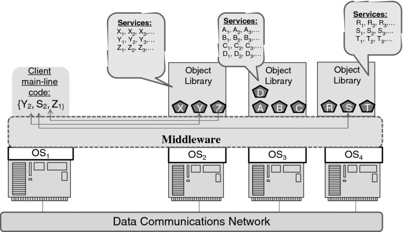
Figure 7.2 Distributed object-oriented computing model.
Here, the client program can invoke remotely the methods of various objects residing across the infrastructure. The infrastructure may include different machines, which run different operating systems. The only requirement of a “physical” nature is that these computers be interconnected through a data network.
Each object library can, of course, be implemented in its own language. The mechanisms of remote invocation have been largely invariant to both the original language and the operating system on which the respective code is to be executed. This has been achieved through middleware, which provides its own primitives (local API) to insulate the programming environment from the operating systems and thus ensure universal portability. As the environment also allowed the object libraries to advertise their services, some models included the concept of a service broker, whose job was to match the client service requirements to various service providers' libraries.
One disturbing development that took place in the mid-1990s, when all eyes were focused on the Internet and the World-Wide Web, was the en-masse rejection of the standards that had been written before then (and most standards that enabled the infrastructure had been written before then). This was not necessarily bad for the standards people, who suddenly got new and exciting jobs; nor was it bad for the new standards fora that mushroomed and pushed aside the older organizations, which had been struggling with completing the standards based on technology that was labeled “old” almost overnight. It was also good for people who had fresh ideas on how to “simplify” programming, because the ebb of fashion propelled many an untested idea into standards. Technology was moving fast, and few companies—and fora that depended on them—risked being left behind. Eventually, when the bubble burst, they were left behind anyway, but the fast development of untested technology proved to be ruinous even for the technology itself!
At the root of the problem was a truly religious aspect of the new wave of distributed processing technology: it was believed that all application-layer protocols had to be ASCII-text-based. The truth is that the Simple Mail Transfer Protocol (SMTP) was indeed ASCII-text-based, which was advantageous at a time when most terminals were teletype-like and using ASCI text was helpful in testing and debugging (and also for breaking in by hackers, although that most certainly was not a design objective!). Similarly, the main protocol of the Web—the Hyper-Text Transfer Protocol (HTTP), initially had to deal only with the transfer of the ASCII-encoded (HTML) files. Since the amount of protocol-related data was small compared with the payload, text-based encoding was justified. But these decisions, which were necessary—or at least justifiable at a time when SMTP and then HTTP were being developed—later somehow became interpreted as the maxim that all Internet application protocols must be text-encoded. The maxim soon became a belief, joining other false beliefs (such as that IPv6 is “better for security” than IPv4). As the application protocols grew, the absurdity of applying the maxim became evident. Not only has the amount of data become huge, but parsing it became a problem for real-time protocols. In fact, the new version of HTTP [7] presently developed in the IETF HTTPbis working group uses binary encoding, providing the following explanation for the change: “…HTTP/1.1 header fields are often repetitive and verbose, which, in addition to generating more or larger network packets, can cause the small initial TCP congestion window to quickly fill.…Finally, this encapsulation also enables more scalable processing of messages through use of binary message framing.”
The effect of text encoding on distributed object-oriented computing first manifested itself in abandoning the Abstract Syntax Notation (ASN.1) encoding standard—which required compilation into a binary format8—in favor of the Extensible Markup Language (XML).9 Nothing is wrong with XML, but using it indiscriminately can be catastrophic.10 Even though HTTP itself provided a mechanism for remote API access, W3C decided to develop an RPC mechanism that ran on top of HTTP. Hence a new protocol—SOAP, the acronym originally expended as Simple Object Access Protocol.11 “The word simple proved to be a misnomer, and so the expansion of the acronym was dropped in SOAP version 1.2.12 SOAP became quite fashionable, and the complex SOA infrastructure was developed on top of it.
While SOAP was (and still is) used as a remote procedure call mechanism, its serialization in the XML format made it perform much worse than the RPC in the Common Object Request Broker Architecture (CORBA) developed by OMG.13 That alone required extra work (and extra standards) for embedding binary objects, but what has proven worse is that SOAP competed directly with the HTTP since it used HTTP as transport. Although, strictly speaking, running on top of the HTTP was not a requirement, the default SOAP/HTTP binding took off, in part because that ensured firewall traversal. (The reader may remember the April 1 RFC mentioned earlier—here is an example of the stuff of a rather cynical joke suddenly materializing as reality.) The result was not only a political confrontation (no one wants his or her application protocol to be a mere transport for someone else's application protocol!) but also a dilemma: either accept the strict client–server structure of the HTTP, in which every communication must be started by a client, and which therefore makes server notifications impossible to implement14 or invent more and more mechanisms to make up for the limitation. But the most serious argument against the RPC approach in general, and SOAP in particular, was that the remote procedure call—as a concept—could not easily adapt to the structure of the Web, which involves midboxes—proxies and caches. As it happened, the industry went on inventing more mechanisms and adding more complexity.
Finally, there was a revolt against SOAP in the industry, with the “native” Web discipline called REpresentation State Transfer (REST). The REST API won, at least for Web access.15 We will discuss the REST principles in the Appendix. For now, we only mention that turning toward the REST style has become necessary because of the “API” in “REST API”—it is something of a misnomer in that it does not involve procedure calls per se. Instead, the programmer writes the application-layer PDUs, the protocol being—for all practical purposes—HTTP. There is no REST standard; REST is merely a style, as we will see later.
Talking about standards, CORBA has been around, and so have SOAP and a few others which may have made fewer headlines. One should never forget Andrew Tanenbaum's aphorism: “The nice thing about standards is that you have so many to choose from!”
In the case of REST vs. RPC though, the division of labor is rather straightforward, owing to the widely implemented three-tier model, which emerged in the enterprise and has become the model of choice for providing software-as-a-service. In this model, Tier 1(a client) issues HTTP-based queries, Tier 2 (a server) provides the business processes logic and data access, and Tier 3 (often a set of hosts running database software) provides the actual data. It is the REST paradigm that is used by clients to access the front end (the second tier) of the service delivery infrastructure; the back-end communications may use RPC and other distributed processing mechanisms.
In the example of Figure 7.3, the client requests a pay stub for a particular employee from the Tier-2 server. The server, in turn, generates the form after querying the corporate databases that contain the payroll records and attendance reports. Of course, this act is performed only after authenticating the user who had requested this information and ensuring that the user is authorized to receive it. (Another example is the now ubiquitous Web-based e-mail service. A Web client speaks REST with the Tier-2 server, which uses the actual mail–client protocols to send and receive e-mail messages from an SMTP mail server.)
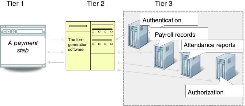
Figure 7.3 An example of the three-tier enterprise model.
Competing standards and non-interworking implementations aside, the advantages for modularity brought about by the architecture and mechanisms outlined so far are clear: nothing could be made more modular than the infrastructure that provided buckets of ready-to-execute service modules, which, on top of everything, could be invoked from anywhere. But its promise went even further—it was expected to reduce IT costs by making programming so easy as to allow the very people who define the business do it, thus eliminating their dependency on in-house specialized software development.
An industry effort to deliver on the promise came in the form of the SOA, which introduced the term orchestration.
7.1.1 The Service-Oriented Architecture
To begin with, we note that there has been much misunderstanding in the industry on what “SOA” means. At the beginning of his authoritative monograph [8], Thomas Erl writes: “I cannot recall any one term causing as much confusion as ‘service-oriented.’ Its apparent ambiguity has led vendors, IT professionals, and the media to claim their own interpretations. This, of course, makes grasping the meaning of a technical architecture labeled as ‘service-oriented’ all the more difficult.”
This is exactly the problem: interpretation. It is a truism, of course, that a vision (in the case of the SOA the vision being remote execution of API-defined services on a distributed computing platform) can be implemented in different ways, which may not necessarily interwork with one another. But once something is specified in detail to ensure a unique interpretation, it risks being labeled “an implementation.”
To this end, the SOA specifications were piling up. First, W3C produced the XML-based Web Services Description Language (WSDL16) for “describing network services as a set of endpoints operating on messages containing either document-oriented or procedure-oriented information.” The WSDL was supposed to be abstract and extensible so as to bind to any protocol, but the specification centered on one binding—specifically binding with SOAP 1.1 over a subset of HTTP.
The standard for the next necessary SOA component—the registry to enable publication and subsequent discovery—was developed by OASIS in the form of the (also XML-based) Universal Description, Discovery and Integration (UDDI) standard.17
Yet another set of SOA components addressed quality of service (a concept which, in this context, has nothing to do with the QoS in data communications), which also included a set of parameters for security (built on the OASIS Security Assertion Markup Language (SAML) standard), reliability, policy assertion, and orchestration per se. The standard for the latter, the Web Services Business Process Execution Language (WSBPEL),18 was produced by OASIS based on an earlier specification created by the joint efforts of IBM, Microsoft, and BEA, in turn inspired by the IBM Web Services Flow Language (WSFL) and Microsoft XLANG.
In a nutshell, WSBPEL uses XML-encoded facilities to specify business process requirements in a manner similar to that used in specialized programming languages to specify the execution of concurrent processes. Both provide facilities for describing parallel activities and dealing with exceptions. A number of other WS specifications were laid out to deal with management and coordination as part of the broad quality-of-service discipline.
Unfortunately, the SOA effort was not the success it had promised to be. By the end of 2005, the UDDI standard alone contained over 400 pages—something few developers had time to deal with, especially since the specifications were filled with the arguably unnecessary new terminology, as is the wont of many standards documents. In December 2005, the SOA World Magazine (http://soa.sys-con.com) published an article19 commenting on the decisions made by IBM, Microsoft, and SAP to close their UDDI registries.
On January 9, 2009, Anne Thomas Manes, a Burton Group analyst, wrote in her blog an obituary for the SOA.20 Citing the impact of the recession (and the resulting refusal of IT organizations to spend more money on the SOA), Ms Manes noted that “SOA fatigue has turned into SOA disillusionment. Business people no longer believe that SOA will deliver spectacular benefits.” The blog though was by no means derisive—it characterized the situation as “tragic for the IT industry” because “service-orientation is a prerequisite for rapid integration of data and business processes” and expressed the need to develop it for the SOA “survivors”—web mash-ups and SaaS. To this end, the blog actually suggested that it is the term “SOA” that is dead, while “the requirement for service-oriented architecture is stronger than ever.”
This was the common sentiment in the industry at that time. When one author googled “why SOA failed,” over three million results came up. On the business side, the blame was almost uniformly laid on the lack of resolve in the IT industry to change. The business people in turn blamed the proponents of the SOA for failing to communicate the importance of the SOA to the business. “Shortage of talent” was yet another explanation, and there were many more.
In our opinion, the SOA history was similar to that of the OSI in the late 1980s. In fact, the fates of the OSI and the SOA are strikingly familiar in at least three aspects, one of which is that both have produced sound metaphors and foundation architectures, which survived the test of time. The second similarity is that both the OSI and SOA standards were challenged by the Internet community. Just as the SOAP-based SOA was declared dead, the REST paradigm was picking up. The third aspect is a fundamental change in the way things were done: The Internet connected private networks and enabled partial outsourcing of networking; the appearance of the Cloud enabled outsourcing of IT services.
Four years later, in an article21 in InfoWorld magazine, David Linthicum noted that SOA practices are absolutely necessary in the Cloud. Perhaps the problem with SOA in the 2000s was the problem with a specific solution to SOA. Furthermore, the SOA referred to earlier was about the application development within the enterprise. In the context of the Cloud, we need a much broader definition. This is why we chose in this book not to describe SOA in any detail. The major surviving SOA concept is that of workflows.
7.1.2 Workflows
In describing a task—any task—one lists all the activities that are involved in carrying the task to completion. Some of these activities may run in parallel; others need to wait for the completion of prerequisite activities. A workflow is a specification that defines and orders all the activities within a task. Naturally, to automate a task involving a distributed system, its workflow must be defined in such a way that it is executable in a distributed environment.
In a way, the whole development of computing has been based on workflows. Hardware is built based on the discipline of logic design, dealing with building circuits by connecting the building blocks—the logic gates—that perform basic operations. Figure 7.4(a) depicts such a circuit.
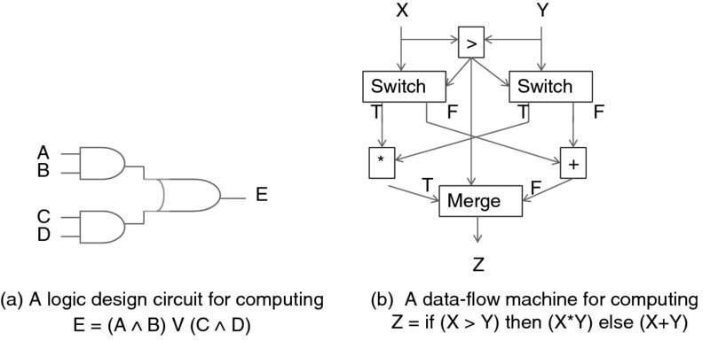
Figure 7.4 Flow-based computing examples.
In the 1980s there was a research movement to build workflow-based computers—then called data-flow machines—from elementary blocks. The blocks are chained as specified by a directed graph, and each block is activated when it receives a message (token). A 1986 MIT memorandum [9] describes the model and issues involved in developing such machines. Figure 7.4(b) (after [9]) gives an example of a data-flow machine that calculates a conditional expression.
In a way, the data-flow machines were workflows built in hardware. It might have developed this way, had it not been for the industry's realization that standardized, ubiquitous computing platforms provided the means for a much more economical (and arguably more flexible) software implementation approach. The trick was to develop software building blocks that could be mixed and matched just as the pieces of silicone could.
Before the introduction of structured computer languages, the algorithms were specified using flowcharts. The flowcharts were suitable for a single-process specification, but proved to be quite unwieldy for describing parallel activities in distributed processing. This is where software-based implementation of data-flow machines—which is, again, what workflows are really all about—helped.
One example, which came from the authors' personal experience, was service creation in telephony. The intelligent network technology, already referred to in this book, was developed in the late 1980s through the 1990s. Its major objective was to enable rapid development of telephony services. “Rapid” meant that the service developers—while being blissfully unaware of the network structure and the distributed nature of the processing—could put services together with the help of a graphical interface by simply chaining icons. Each icon represented a service-independent building block (such as queue_call or translate_number). Thus, a complex 800-number service, which involved time- and location-based translation, playing announcements and gathering input, and so on, could be programmed in minutes. Of course, the execution of each service-independent building block was in itself a complex distributed activity. Yet, since it was contained in a ready module, the service programmer was not concerned with that complexity. In modern terms, each service was programmed as a workflow. An attempt was even made to coordinate the call establishment with billing and charging processes. (As no standard was developed, several service-creation environments existed, but it was not trivial to merge them. In the mid-1990s the authors researched the means of unifying several such environments in AT&T, reporting on the results in [10].)
Figure 7.5 elucidates the general concept of workflow specification and execution. On the left-hand side, a workflow program is represented as a directed graph of activities. (This almost looks like a flowchart, although, as we will see, there is a significant difference.) Specifically, Activity 1 is the first such activity, which starts the workflow. Each activity—with the exception of the last, terminal, activity—has an output directed toward the next activity, said to consume the output, in the chain. In principle, activities can loop back, although the figure does not display such an example.
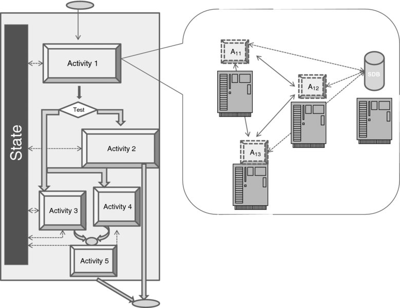
Figure 7.5 Workflow as a directed graph of activities.
Once an activity completes, the next activity can be selected via a conditional test. In our example, the test block determines whether Activity 2 is to start after Activity 1 and consume its output. If not, two activities—Activity 3 and Activity 4—are to execute concurrently. The example demonstrates that it is possible to synchronize the execution of both activities, by making the checkpoint (CP) wait for the completion of both activities before filtering their respective outputs to Activity 5. Supporting concurrency makes a workflow specification different from that of a flowchart. Another difference is that a workflow specification maintains its explicit state (depicted in a block on the left), which is read and updated by all activities.
So far we have discussed only a specification of a workflow. The execution is a different matter altogether, and it is explained by the right-hand side of Figure 7.5, which expands Activity 1. As we can see, here it is executed by three processes—A11, A12, and A13—which run on three different machines. The state database is maintained (in this example) on yet another machine. Of course, it is non-essential that A11, A12, and A13 run on separate hosts—they could be distributed between two hosts or even run on the same host; nor is it essential that they are processes rather than threads within a single process. The ingenious part of the arrangement is that the choice of the execution host and the form of the execution is absolutely flexible—it is left to the run-time environment. Similarly, the location of the state database (which, in fact, may also be distributed) is irrelevant as long as it meets the performance requirements. To increase reliability, and also to improve performance, the state database may be replicated. Soon, we will see this principle applied to the design of OpenStack.
One other aspect of improving performance is workflow optimization. If a workflow specification language is formally defined (so that it can be parsed), it is possible to apply the compiler theory to eliminate redundancies and—most important—optimize scheduling of parallel activities. But it is also possible to analyze the performance of a workflow statistically, as it repeats, to discover performance problems. This approach, illustrated in Figure 7.6, is called path analysis, and it is particularly useful in the workflows that implement diagnostic tools.
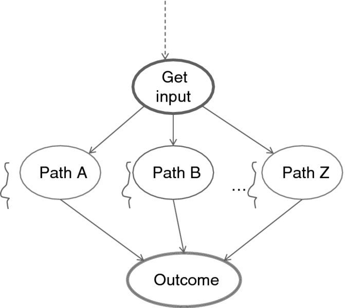
Figure 7.6 Path analysis.
Starting from some place within a workflow where an input has been gathered there may be several ways—represented by paths through the workflow graph—to achieve an outcome. An inference that among the paths A, B, …, Z the path B is a shortcut in terms of the execution time may very well suggest to the workflow designer that other paths be eliminated to streamline the workflow.
There is a significant volume of literature and a number of products related to workflows. We refer only to a few examples.
An earlier grid-related research project, GridAnt, is described in [11] along with a survey of the then-existing commercial products. A research paper [12] provides an overview of several workflow optimization algorithms and proposes an extended one (the Boolean verification algorithm) that deals with the workflows that contain conditional branches and cycles.
As far as products are concerned, the Microsoft Windows Workflow Foundation is described on a dedicated site.22 This site also contains an excellent tutorial.
Amazon provides the Amazon Simple Workflow Service (AWS) API along with the AWS Flow Framework to invoke these APIs23 from user programs. A developer needs to specify coordination logic (sequencing, timing, and failure response) as well as the code for each step of the workflow. To this end, a library of commonly used programming patterns in support of coordination logic is also available.24
So far we have discussed the generic use of workflows in applications. Later in this chapter we will return to this subject, but we will narrow the focus of the discussion to the application of workflows to the specific task of Cloud orchestration. Yet, before doing so, we need to review the concepts and techniques of network and operations management.
7.2 Network and Operations Management
As we noted earlier, the discipline of network management predates that of data communications. It started with telephone networks, and it has been driven solely by automation. As the telecommunication network equipment evolved from human-operated switching boards to computer-controlled switches that processed call requests automatically, the need to control individual calls morphed into the need to control the equipment that controlled the calls. Furthermore, with the introduction of time-division multiplexing, the operation of the transmission equipment itself has become complex enough to warrant real-time monitoring and administration activities.
In the Bell Telephone System [13],25 as in all other major telephone companies, these activities—commonly called network-related operations—were part of the overall company operations, which included provision of services to the customer, service administration, and maintenance operation. Incidentally, we are not mentioning these for purely historical (or even historic) reasons—these activities remain at the heart of the Cloud today! Interestingly enough, a good deal of software technology concepts, as we see them today, were developed to streamline network operations.
The administrative processes were initially performed manually, but during the magic 1970s they had been increasingly moving to computerized processing. Separate systems were developed—one for each piece of equipment to be administered. Initially, Bell System was purchasing various mainframes to host the operations support software, but when the DEC PDP-11 line became available (as did the Unix operating system, which was first developed for PDP-11), its minicomputers were used for the development of the Operations Support Systems (OSSs).26 Ultimately, because the Unix operating system could run on any computer, the particular choice of hardware became less and less relevant. In the late 1980s, the largest part of the software research and development in Bell Laboratories27 was dedicated entirely to the design of OSSs.
OSSs required more or less the same capabilities that any business administration would, but on a much larger scale because the telecom domain contained thousands of pieces of autonomous computer-based equipment (not to mention hundreds of millions of individual telephone lines!), further governed by various business processes and US government regulations.
In the 1980s, the objective of the OSS development was to have a universal OSS which would govern all activities, but this was a tall order.28
To begin with, the business activities were disconnected across the company. When a telephone service was requested, it had to be processed by the business office. Sure enough, a customer record was created in one or another database—most likely in several—but it could not reach the local switch's database automatically. According to a Bell Labs anecdote of the time, an operator of the switching exchange management system, which was accessed through a dedicated terminal, needed to turn in a swivel chair to use another terminal to log into the order system to read the customer order record and then turn back to retype the information into the switching system. Apparently, this is when the term “swivel chair integration” was coined.
To be precise, the independent operations support systems were—and largely still remain in the telecom world—as follows:
- Trunks integrated record-keeping system.
- Plug-in inventory control system.
- Premises information system.29
- Total network data system.
- Switching control data system.
- Central office equipment engineering system.
- A number of facility network planning systems.
In addition, in the 1970s AT&T developed a central network management system, which was showcased at the Network Operations Center, Bedminster, NJ.30 There, the updates from all over the network were displayed on a wall-sized map of the United States, indicating the state of the network. The network managers, working at individual terminals, were able to take corrective action when necessary. This was the first decisive step toward network (vs. element) management. In the second half of the 1980s, central network traffic management systems were developed by AT&T's Network Systems division for sale to regional operating companies and abroad.31
Back to the unified OSS vision. Again, the major obstacle in its way was that in Bell System alone multiple systems had evolved separately, without any common platform.32 Rewriting all this software was out of the question, but even if a decision were made to rewrite it, there was still no standard which different vendors could implement. As the vision was built around the ISDN technology, in which telephony services were combined with data communications services, the first step was (naturally) to integrate the management of the data communications network. The latter had morphed into a discipline of its own, starting with the ISO OSI network management project with its five-item framework. This framework is still all-encompassing; we describe it in the next section.
7.2.1 The OSI Network Management Framework and Model
The first aspect of the framework is configuration management, and it is concerned with the multitude of parameters whose values need to be maintained within specified ranges on all the devices in the network. The values of some parameters may be changed directly by the network owner; others can be read-only.33
The second aspect of the framework deals with fault management. The word “fault” broadly refers to any abnormal condition in the network. One big design task here, of course, is to define clearly all events that correspond to changes from “abnormal” to normal. Another design task is to select those events that are worthy of being detected on the one hand, and on the other hand to ensure that the reporting of these events does not overwhelm the system's processing power. A typical event constitutes a change of a parameter value beyond a certain threshold. The change is (often) logged and reported in real time through an alarm mechanism. (Recalling an earlier discussion of the computer architecture and operating system, this situation is very similar to a CPU interrupt flag being raised by a device, and, indeed, just as an operating system needs to supply an interrupt handling routine, so does the network management system needs to supply a proper operating procedure.) Note that in order to detect a change (as well as to react to it), the configuration management mechanisms need to be invoked.
The third aspect of the framework is performance management. This, again, relies on the configuration management mechanism to measure the utilization of the network resources in real time. A longer-term part of this activity is capacity planning. It is pretty obvious that when a given resource becomes overwhelmed so as to affect the overall network performance, it may be high time to replace it with a larger one (but determining which resources contribute to a bottleneck is a complex problem). As replacing or beefing up the equipment is often expensive, effective capacity planning can save much money.
The fourth aspect is identity and access management, addressed in the last section of this chapter. In a nutshell, the task of access management is to ensure that every single attempt to learn any information about the network—or to change anything in it—is captured and allowed to proceed only after it is determined that the attempting entity is properly authorized to do so. Typically, the attempts to access critical data are logged and otherwise processed through the fault management mechanisms.
The fifth and final aspect is accounting management. This involves the whole range of activities that deal with charging for the use of resources. In an enterprise network comprising several organizations, this may mean determining a proportion of the overall communications bill that each organization should pay. In an operator's network, this is the activity that determines the revenue.
While the framework has been clear—and it remains unchanged for the Cloud—the development of network management standards has proven to be rather erratic, with competing parallel activities carried by several organizations and still inconclusive results.
Historically, the above five aspects, spelled out in a different order—Fault, Configuration, Accounting, Performance, and Security—and thus known by the acronym FCAPS, formed the basis for the ISO work, later carried out jointly with ITU-T. In parallel, and according to the same model, the IETF was developing its own protocol series. We will briefly address both, but we start with the common basic model, as depicted in Figure 7.7.
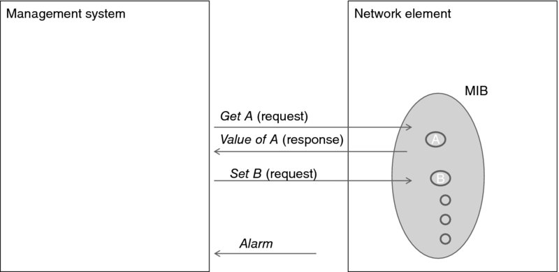
Figure 7.7 The basic network management model.
Each managed device is associated with the Management Information Base (MIB), which actually defines the configuration parameters. The management system may request (Get) the value of a parameter as well as change (Set) this value. Which values may be changed externally (and, if so, by whom) is part of a MIB specification. (There are also other capabilities with respect to the parameters—such as learning which parameters are defined within the MIB—and many nuances to defining the managed objects.) An alarm or trap message is a notification from the device, which can only be processed as an interrupt at the machine hosting the management system.
ITU has developed, jointly with ISO/IEC JTC 1, the Common Management Information Protocol (CMIP), defined in [15] and other ITU-T recommendations in the X.700 series. As CMIP was using the OSI application-layer services (such as the OSI Remote Operations Service Element) that were unavailable in the Internet, the IETF had decided to proceed with its own protocol, and here the development of the network management standards forked.
Based on CMIP and other modules, ITU-T has come up with a large set of specifications (the M.3000 series) called the Telecommunications Management Network (TMN), while the IETF has produced the so-called Simple Network Management Protocol (SNMP), now in its third version SNMPv3. The enterprise IT industry has deployed SNMP exclusively, while TMN is deployed in the telephone networks—notably in WorldCom, as reported in [16]. This divergence is rather unfortunate, as it has contributed to enlarging the difference between telephony and IT—the very difference that the network management standardization effort was supposed to eliminate!
The SNMP STD 62 standard was completed in 2002, reflecting more than 10 years of SNMP development. By 2003, when the IETF Internet Architecture Board had a workshop,34 SNMP was widely deployed, with some MIBs implemented on most IP devices. Hence the industry had obtained enough operational experience to understand the technology limitations. The major one was that SNMP dealt primarily with the device monitoring aspect of network management (as opposed to the configuration aspect).
We should stress that device monitoring was—and remains—an important function because it has provided, among other things, notifications (“traps”) of the state of physical equipment (such as a server board or a simple fan). Knowing that hardware works properly and detecting a malfunction as early as possible is the foundation of the operations discipline. In modern data centers, such SNMP traps are fed into specialized monitoring systems (such as Nagios)35 used as part of the modern solutions based on the development operations (devops) methodology.
Although the use of SNMP for configuring devices was not unheard of (after all, the protocol explicitly supports changing device parameters via a SET method!), many standard MIB modules lacked writable objects. With SNMP, it is not easy to identify configuration objects, and, as RFC 3535 documented, the naming system itself seemed to be in the way of playing back a previous configuration of a reconfigured system. But even if all MIBs were perfect, SNMP is, too low level for network operators—who lamented that not much had been done in the way of developing a bird's-eye view of application building blocks.
Nor might the development of such building blocks help, as the SNMP software started to reach its performance limits. Retrieving routing tables, for example, proved to be very slow. Another set of problems was caused by the objective of keeping things simple (as the “S” in SNMP might indicate). Sure enough, the protocol was simple enough—compared with CMIP—but this has merely left the complexity to the developers to deal with. Now it was the network management application that was supposed to checkpoint the state of SNMP transactions,36 and be prepared to roll a device back into a consistent state. Designing such an application required significant experience with distributed processing, and even for the experts it was by no means a simple task. This was at cross purposes with the plan to make network management applications “easy” to develop (i.e., cobbled by non-programmers from some elementary building blocks). More generally, as RFC 3535 states, there was “often a semantic mismatch between the task-oriented view of the world usually preferred by operators and the data-centric view of the world provided by SNMP. Mapping from a task-oriented view to the data-centric view often requires some non-trivial code.”
And then the “simplicity” resulted in under-specification, which hindered interoperability:
“Several standardized MIB modules lack a description of high-level procedures. It is often not obvious from reading the MIB modules how certain high-level tasks are accomplished, which leads to several different ways to achieve the same goal, which increases costs and hinders interoperability.”
Part of the problem with the ineffectiveness of SMNP with respect to configuration management is the very model in which the network manager (presumed to be “intelligent”) deals with a “dumb device.” Initially, the devices (a modem is a good example of one) were indeed not programmable, but by the late 1990s the situation had changed drastically. To appreciate the difference, consider what happened to the concept of a home network, which evolved from a bulky modem, connecting a computer to a telephone line, to an Ethernet LAN hub (although relatively few people had this in their homes), and then to the present WiFi base-station router with built-in firewalls and a NAT box. Beside the obvious differences, here is a fairly subtle one: the complexity introduced with all this equipment required that configuration changes be made according to a specific policy.
For more detail on SNMP, we refer the reader to the next chapter.
7.2.2 Policy-Based Management
The IETF started to address the problem gradually, strictly on a specific need basis. The first such need was the policy configuration in support of QoS. Here, the device (typically, a router) is by no means dumb: its configuration needs to change continuously—in response to users' requirements– and so the management system needs to propagate the change into a device from a local copy. Here, the model introduced a new challenge—the need to maintain a synchronized state between the network manager and the device. Another challenge came from the potential interference among two or more network managers administering the same device.37 That case introduced the potential to corrupt the device with contradictory changes.
And then there is a need for policy-based management. While a device may have to change in response to users' requests, it is hardly acceptable to allocate network resources based only on user requests—that is, always give whatever one asks. Network providers wanted to have a mechanism that would enable granting a resource based on a set of policy rules. The decision on whether to grant the resource takes into account information about the user, the requested service, and the network itself.
Employing SNMP for this purpose was not straightforward, and so the IETF developed a new protocol, for communications between the network element and the Policy Decision Point (PDP)—where the policy-based decisions were made. The protocol is called Common Open Policy Service (COPS); we review it in the Appendix.
As an important aside, COPS has greatly influenced the Next-Generation telecommunications Network (NGN) standards, which have been developed since 2004 in both ETSI and ITU-T. NGN is characterized, among other things, by (1) the prevalent use of IP for end-to-end packet transfer and (2) the drive to convergence between wireline and wireless technologies.38
In contrast to specialized networks optimized for specific applications, NGN has been envisioned as a general multi-service network that would meet a wide range of application performance needs and security requirements. To this end, service control was to be separate from transport as well as from the mechanisms required to allocate and provide—often in real or near-real time—network resources to applications.
One specific set of such applications emerged to support the so-called triple-play services, which encompass Voice-over-IP (VoIP), IP television (IPTV), and Internet access. These applications required—and still require—special QoS treatment.
As we saw in Chapter 4, the performance needs of applications are characterized by four key parameters: bandwidth, packet loss, delay, and jitter (i.e., variation in delay), which determine the quality of service. Overall, the needs of the triple-play services are different with respect to QoS. For example, some popular data applications (such as e-mail and web access) require low to medium bandwidth and are quite relaxed as far as delay and jitter are concerned. In contrast, VoD flows have relaxed requirements on delay, but they do need high bandwidth and cannot tolerate much packet loss or jitter. VoIP, while tolerating some packet loss, needs much lower bandwidth than VoD, but it can tolerate neither long delay nor jitter.
In addition to the QoS-related resources, networks often need to grant other resources (e.g., IP addresses or service-related port numbers) to the endpoints and the processes that execute on them. As we may recall from Chapter 5, this specific need arose from NAT LSNAT deployment, which has been employed to hide the internal network topology. These diversified and already complex tasks were further complicated by the very structure of the NGN, which combines several network types, including Asynchronous Transfer Mode (ATM), Digital Subscriber Line (DSL), Ethernet, and fixed and mobile wireless access networks.
The key to fulfilling this complex duty was a dynamic, policy-based resource management framework, known as the Resource and Admission Control Functions (RACF), described in [18] (the ITU-T standard published in [19]). An important point to emphasize is that RACF was put in place to interwork the real-time processing with OSSs; RACF have both functions, and their protocols combine both sets of building blocks.
Even though RACF was influenced directly by COPS, its framework also relied on a number of IETF protocols other than COPS.39 Starting from their inception, the Third-Generation Partnerships—3GPP and 3GPP2—have been following and influencing the development of the IETF building blocks in support of the IP Multimedia Subsystem (IMS).40
While the Third-Generation Partnerships were focusing on the needs of wireless carriers, the ETSI Telecommunication and Internet Converged Services and Protocols for Advanced Networks (TISPAN) group embarked in 2003 on a project that dealt with fixed access. Its approach to resource management was reflected in its Resource and Admission Control Subsystem (RACS), published in [21].
We should emphasize again that the need to control Network Address and Port Translation (NAPT) and NAT traversal was an important driver for the ETSI work. When service providers started deploying VoIP, they discovered the complications—which we now know very well—caused by the end users being located behind NAT devices (as is the case for most broadband access users). This problem could be circumvented with session border controllers supporting hosted NAT traversal. Standalone session border controllers, however, do not fit well in the overall IMS approach. In contrast, the RACS model supports NAPT and hosted NAT traversal as part of policy enforcement under the control of a policy decision function that interfaces with IMS session control.
In 2004, ITU-T embarked on the RACF effort with the objective of preserving the separation of services and transport while enabling dynamic, application-driven, policy-based end-to-end QoS and resource control capabilities (in particular, resource reservation, admission and gate control, NAPT, and hosted NAT traversal within the network domain and at network boundaries. From its onset, the scope of the RACF included various types of access and core networks. To this end, RACF was the first attempt to create a flexible end-to-end resource management solution by blending (rather than replacing) the existing standardization results within a common framework.
As we can see, COPS has solved the problem of policy-based management, but it has not solved the problem of managing configurations effectively. Going back to RFC 3535 (which, as the reader may remember, reports on the 2002 IAB workshop), the prevailing complaint from the operators was the lack of a consistent, all-encompassing configuration discipline. Neither COPS nor the ever-growing IETF set of MIBs was helpful here.
Hence, one objective of the workshop was to determine how to refocus the IETF resources.41 The workshop made eight recommendations—both positive (which activities to focus on) and negative (which activities to stop). Of these, the only positive recommendation that enjoyed “strong consensus from both protocol developers and operators” was that “the IETF focus resources on the standardization of configuration management mechanisms.” Two other recommendations, apparently supported more by the operators than the protocol developers, were that the resources be spent “on the development and standardization of XML-based device configuration and management technologies” and not be spent on the HTML-over-HTTP-based configuration management.42
To the IETF's credit, it turned out to be quite nimble, responding decisively. In 2003, the NETCONF WG was created, and three years later it had published the first version of the NETCONF protocol. That was augmented in the next two years to incorporate notifications and several classical distributed processing and security mechanisms, and the protocol kept evolving for the next eight years. The present version of the base NETCONF protocol was published as RFC 624143 in June 2011. (Its extensions have been published in separate RFCs.) We review NETCONF in detail in the next chapter.
Meanwhile, the industry has created several configuration management tools, which have been used extensively in today's Cloud. In the rest of this section we review two well-known examples: Chef by Chef44 (formerly Opscode) and Puppet by Puppet Labs.45
With Chef, an administrator describes the structure of the distributed system (which might include web servers, load balancers, and back-end databases) using what is called recipes. These recipes describe how the entities within the structure are deployed, configured, and managed; they are stored at the Chef server. The Chef clients are installed on the respective nodes (which could be virtual machines). The job of the Chef clients is to keep the software on its respective node up to date, which it achieves by checking the compliance with the latest recipe installed at the Chef server and automatically updating the software as necessary. At the moment of this writing, the company provides free experimentation as a learning tool (and even limited free software distribution) at its website, which we highly recommend to the interested reader.
Puppet automates the same configuration tasks similarly, as it is also based on the client–server model. The main difference from Chef is in the specification method. The Puppet specification (which uses its own DSL) is declarative—it specifies the dependencies and the client ensures that these are followed. The Chef specification, in contrast, is procedural—written in the Ruby language. Just as Chef, Puppet is available as open source. There is an incisive article [22] comparing the two.
7.3 Orchestration and Management in the Cloud
We are ready to start putting together the pieces of the puzzle developed in this chapter and elsewhere in the book. The elements of the management of the physical elements of the data centers and the network interconnection have already been introduced. The piece that we have not touched on is the management of the life cycle of a Cloud service.
In addition to many technical aspects (such as creation and bootstrapping of images), here the business aspects enter the picture. An excellent introduction to the subject matter has been produced by the Distributed Management Task Force (DMTF)46 organization, and so we will use the definitions and concepts described in the DMTF white paper, Architecture for Managing Clouds.47 We address the life cycle of a service in the next section. The sections that follow review the orchestration and management in OpenStack.
We need to emphasize here that orchestration can be implemented at various levels. As we started this section with a musical simile, we will complete it with the same. Ultimately, in an orchestra each musical instrument needs to have its own part. These parts may be shared among the “clusters” of musicians (e.g., first or second violin sections), but ultimately the individual parts are combined into sections, and then into a single score—the overall composition that the conductor deals with.
In the extreme—and somewhat degenerate—case, each VM in the Cloud can be configured, monitored, relocated, and so on, manually by its own administrator. This task can be automated using tools (such as Chef or Puppet).48 This is where the VM (an “instrument”) is accompanied by its own score. At the next level, the whole infrastructure (the VMs along with the network components to interconnect them) can be orchestrated according to a uniform “score”—and this is what the OpenStack example will demonstrate. But things can go even further! At the top layer, a “score” can be written that combines business policies with the infrastructure specification. This can be achieved with the Topology and Orchestration Specification for Cloud Applications (TOSCA), an OASIS standard, which we will review in the Appendix.
7.3.1 The Life Cycle of a Service
The three entities involved here are the Cloud service provider, the Cloud service developer, and the Cloud service consumer.
Suppose the Cloud service developer needs to create a (typical) web services infrastructure—say three identical servers and a load balancer along with a back-end database. Writing a program that issues individual requests to the Cloud service provider for creating all the instances—and networks—is problematic in more than one way.
First, suppose the instances for a load balancer and two servers have been created successfully, but creating the virtual machine for the third server has failed. What should the user program do? Deleting all other instances and restarting again is hardly an efficient course of action for the following reasons. From the service developer's point of view, this would greatly complicate the program (which is supposed to be fairly simple). From the service provider's point of view, this would result in wasting the resources which were first allocated and then released but never used.
Second, assuming that all instances have been created, a service provider needs to support elasticity. The question is: How can this be (a) specified and (b) effected? Suppose each of the three servers has reached its threshold CPU utilization. Then a straightforward solution is to create yet another instance (which can be deleted once the burst of activity is over), but how can all this be done automatically? To this end, perhaps, maybe not three but only two instances should have been created in the first place.
The solution adopted by the industry is to define a service in more general terms (we will clarify this with examples), so that the creation of a service is an atomic operation performed by the service provider—this is where orchestration first comes into the picture. And once the service is deployed, the orchestrator itself will then add and delete instances (or other resources) as specified in the service definition.
Hence the workflow depicted in Figure 7.8. The service developer defines the service in a template, which also specifies the interfaces to a service. The template (sometimes also called a recipe in the industry) specifies various resources: VM images, connectivity definitions, storage configuration, and so on.
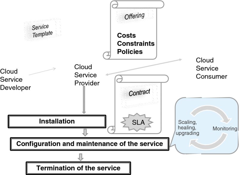
Figure 7.8 The service life cycle.
The service provider creates an offering for a service consumer by augmenting this template with the constraints, costs, policies, and SLA. On accepting the offering, the consumer and provider enter into a contract, which contains, among other items, the SLA and a set of specific, measurable aspects of the SLA called Service-Level Objectives (SLOs).49
At this point, the provider may modify the template to fit the contract requirements. Based on the template, the provider then deploys (or provisions) the service instance. Provisioning involves committing the resources necessary to fulfill the contract.
Once deployed, the service is maintained until the contract is terminated and so the service ends and the resources committed to its support are redeployed. From the orchestration point of view, an essential part of service maintenance is monitoring. Here the relevant events are collected and acted on automatically so as to scale—up or down—the capacity or heal the service in case of a breakdown. Similarly, upgrades are handled automatically in this phase, too. The auto-scaling and auto-healing capabilities are two major functions of orchestration.
As we can see, the model implies that the business objectives and interface definitions be expressed (i.e., encoded) in some form. The formal language constructs for doing so are developed in the Telemanagement Forum (TMF).50 The synergies between the DMTF and the TMF have been explored in the joint DMTF/TMF White Paper, Cloud Management for Communications Service Providers.51
Let us start with onboarding.52 Here a service developer needs to specify which applications run on which virtual machines, what kinds of events an orchestrator needs to handle (and what exactly to do when such an event occurs), and what information to collect.
An application recipe (or template) describes the services that the application requires, each service further defined as a group of service instances (running on separate VMs). These are provided as file descriptors. Services are further specified in individual recipes that specify (a) the number of instances, (b) the hardware and software requirements, and (c) the life cycle events along with their “interrupt handlers,” which are the pointers to the respective scripts. In support of network and operations management, a recipe can also specify probes for monitoring and configuration management. In addition to pre-defined probes available to a service developer, the latter may plug in independent scripts. One aspect of Cloud management and orchestration is that a Cloud provider's resources that are needed to fulfill obligations to customers must be used optimally (as far as the cost is concerned). Optimization here is a complex task because of the many constraints, which include compliance with a customer's policies and various regulations.
The other aspect is providing a customer with the orchestration tools so the customer may control its own infrastructure. Ultimately, what is good for the goose is good for the gander: a provider may share some of its own orchestration tools with customers. Inasmuch as the orchestration involves interworking with business activities, employing workflow-supporting tools is becoming an expected feature. For instance, the VMware® vCenterTM OrchestratorTM provides53 a pre-built workflow library along with tools to design customized workflows. The new blocks for workflows can be created using a JavaScript-based scripting engine. The policy engine launches the appropriate workflows in response to external events (and according to defined policies).
Another important example—and in a way a benchmark for orchestrators—is the Amazon AWS CloudFormation service54, which provides a mechanism for managing the AWS infrastructure deployments. As we will see, the OpenStack orchestrator, Heat, has adopted the terminology as well as the template format of AWS CloudFormation, and in its early orchestration offer did much to interwork with the same tools and interfaces that AWS CloudFormation had given its users.
With the AWS CloudFormation, all resources and dependencies are declared in a template file. Each template defines a collection of resources pertinent to a service, along with the dependencies among them. The collection, which actually represents an infrastructure, is called a stack.55 The idea is that the multitude of resources within a given stack are treated as a single entity, which can be created (or deleted) with a single create or delete command.
Furthermore, when a template for a stack is updated, the stack gets updated (automatically), too. Furthermore, once a template is specified, the whole stack can be replicated or even moved into a different data center or even a different Cloud.
Figure 7.9 illustrates this concept. Here, the template defines the infrastructure that we discussed earlier: a load balancer distributing the traffic among three identical servers. To make the service look realistic, we also added the back-end database. Two networks are involved: one to be shared among the load balancer and the servers, and the other among the servers and the database. With a sequence of < ?TeX{? >create, delete, create< ?TeX}? > operations, the whole infrastructure is first created in one Cloud and later replicated in another. (Of course, this assumes that both Cloud providers support the same template. As we will see in the next section, the OpenStack project has achieved just that by creating a standard along with the software for implementing it!)
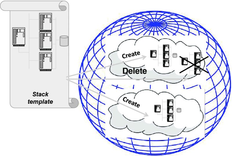
Figure 7.9 Operations on a stack (an example).
In line with the ideas outlined at the beginning of this section, we stress that when a stack is created (or deleted), all resources specified in a template are instantiated (or deleted) simultaneously. During the lifetime of a stack, the declared interdependencies among the resources are maintained automatically.
To begin with, Amazon deployed CloudFormation endpoints—with known URLs—across the world regions. Referring to the local geographic endpoint reduces latency. As we will see, some functional capabilities rely on the choice of endpoints.
The template is written in the JavaScript Object Notation (JSON) format.56 In addition to the version and description fields, it has the following entries: resources, parameters, mappings, conditions, and outputs. We review them, in that order, with the help of Figure 7.10.
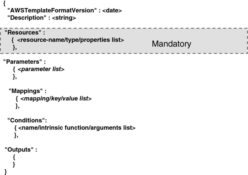
Figure 7.10 The AWS CloudFormation template.
The term resource refers to a VM instance or any other AWS pre-defined object (such as a security group, or an auto-scaling group—we will see specific examples soon).57 Each resource is assigned a resource name, which must be unique within a template. The resource type is another part of the resource specification. In addition, a set of resource properties associated with a resource may be declared, too, each declaration taking the form of a name/value pair. A property's value may be known only at run time, and so the template syntax allows the use of an intrinsic function instead of a static value. The resource entry is the only mandatory one; the rest are optional.
A parameter is just a name string, whose specification may list the conditions that constrain the values that parameters can take.
Mappings automate the parameters' value assignments. One can define a subset of parameter's values and associate it with a key. A typical example of a key is the name of a region; all region-specific values (e.g., current time or local regulations) are assigned to the respective parameters automatically.
Conditions are but a programmatic tool. These are Boolean functions that compare parameter values, either with one another or with constants. If the result of a comparison is positive, resources are created. All conditions are evaluated when a stack is (a) created or (b) updated (and only then).
Outputs are parameters declared specifically in support of the feedback mechanism. The end user can query the value of any output via a describe-stack command. Again, conditions can be employed to guide the value assignment.
Going back to our earlier example of a web service, we can see how a template may be constructed in support of auto-scaling— an orchestrator-provided service that enables elasticity. In AWS in particular, auto-scaling enables launching or terminating an instance according to user-defined policies as well as run-time characteristics (such as an application's “health” gauged through monitoring). Scaling can be achieved vertically, by changing the compute capacity of an instance, or horizontally, by changing the number of load-balanced instances. It is particularly the horizontal scaling that demonstrates the unique economic advantages of the Cloud environment: in the physical deployment, there is a need to keep additional servers on standby in anticipation of increased load—or actually load balance all of them, while they are under-utilized—but in the Cloud environment an additional server instance may be deployed on the fly, the moment the demand reaches a specified threshold. Conversely, when the demand drops sufficiently, a superfluous instance can be shut down. As a result, the expenditure for the extra resource is incurred only when the resource is needed.
A template58 for operating the environment that involves a group of web servers would specify under the Resource header a group of the type “AWS::AutoScaling:: AutoScalingGroup,” with the properties that list the availability zones, the configuration name (another resource, pointing to the image of the instance to launch), and both the minimum and a maximum size of the group.
If notification of the events to the operator (an interesting feature!) is desired, the notification topic can also be specified as a resource with the type “AWS::SNS::Topic,” which would refer to the appropriate resource—the endpoint (the operator's e-mail)—and specify the protocol (“email”). In this case, the common group specification would also list specific notification message strings (e.g., “instance launched,” “instance terminated,” or “error,” the latter also supplying an appropriate error code).
Next, the scale-up and scale-down policies can be specified, using the resource type “AWS::AutoScaling::ScalingPolicy”. The actual alarm event that triggers scaling up (or down) can be specified as the resource, too: “Type”: “AWS::CloudWatch::Alarm.” For instance, if the requirement for scaling up is a burst of CPU utlilization exceeding 80% for 5 minutes, the properties of the scaling-up alarm will include, using the “WS/EC2” namespace, “MetricName: CPUUtlilization,” “Period: 300,” and “Threshold: 90.” The “AlarmActions” will refer to the name of the scale-up policy defined above. The intrinsic function used here is “ComparisonOperator,” with the value “GreaterThanThreshold.”
Another resource that needs to be specified is the load balancer itself, of the type “AWS::ElasticLoadBalancing::LoadBalancer,” with properties that include the port number to listen to and—given that we deal with web servers—the instance port number and the protocol (HTTP).
Last but not least, a resource describing the instance security group of the type “InstanceSecurityGroup” must be created. The typical use is enabling Secure Shell (SSH59)-based access to the front end, the load balancer, only.
The Parameters section defines the structures referred to above: the types of instances allowed, specific port numbers, the operator's e-mail, the key pair for SSH access, and the (CIDR) IP address patterns.
The Mappings section supplies the parameters' values (pre-defined in AWS), and the Outputs will list the only output—the URL of the website provided by the server. This can be achieved using intrinsic functions. The scheme of the URL is, of course, always “http”; the rest of the string is obtained via an intrinsic function GetAtt, with two parameters—the name of the elastic load balancer resource, specified in the Resources section, and the string “DNSName.” These two strings can be concatenated using the intrinsic function Join,60 with an empty delimiter. Thus, if the name of the elastic load balancer is MyLB, the Outputs section will look as follows:
"Outputs":
    {
     “URL”:
        {Value'':
           {"Fn::Join": ["",[http://",
              {"Fn::GetAtt": ["MyLB",
                "DNSName"]
           }]]
        }
    }
We went into this level of detail in describing the AWS CloudFormation example for a good reason, as already mentioned—it is a benchmark. To this end, the same template is accepted by the orchestrator in OpenStack, which we review in the next section. Of course, the template merely defines what needs to be done; the how is a different matter. The fact that OpenStack is an open-source project allows us to understand the inner workings of Cloud orchestration—and even to participate in the development of its software.
As we said earlier, orchestration can be performed at different levels. We will address one implementation of the orchestration at the stack level in the next section and return to the orchestration that involves business logic in the TOSCA discussion in the Appendix.
7.3.2 Orchestration and Management in OpenStack
First, a few words about OpenStack itself. In the organization's own words,61 its software “… is a Cloud operating system that controls large pools of computing, storage, and networking resources throughout a datacenter, all managed through a dashboard that gives administrators control while empowering their users to provision resources through a web interface.”
The project is supported organizationally by the OpenStack Foundation. The latter's funding comes—at least in part—from corporate sponsorship, but otherwise the OpenStack Foundation has attracted thousands of members with its personal membership, which is free of charge. The strategic governance of the OpenStack Foundation is provided by its Board of Directors, which represents different categories of its members. The Technical Committee defines and directs the technical direction of the OpenStack software. The software users' advocacy and feedback is carried out by the User Committee. The structure and up-to-date information on the OpenStack Foundation can be found on its site: www.OpenStack.org/foundation/.
In fact, in describing the OpenStack components, this section is a culminating point of the book in that it finally brings together the material of other chapters. The software components of the OpenStack correspond exactly to the functions studied in the previous chapters—there is a component for compute (i.e., administration of the host that provides a CPU shared by the hosted VMs), which enables virtualization; there is a component in charge of networking; and there is a component in charge of storage. Interacting with all these there are management functions, which notably include those of orchestration and identity and access management (to be addressed in the last section of this chapter). Note that we were careful in calling these pieces “components,” because neither of them represents a simple architectural entity—such as a machine or a process or a library. As we will see shortly, some components combine executable images, various libraries, and shell scripts.
In line with the API terminology that we discussed earlier, the part of a component that implements an HTTP server (and is thus accessed via a REST API) is referred to by the OpenStack documentation as a service. It is important to understand that deployment of the OpenStack software on physical hosts is a separate matter altogether. Overall, there is no single way to deploy these components. We will provide specific examples; for now we note that the deployment issues pretty much boil down to ensuring reliability commensurate with the operating budget.
First, let us take a closer look at the components. Each component is associated with a separate project in charge of its software development. The names of the components and their associated projects are used interchangeably by the OpenStack documentation.
The OpenStack Compute component (developed in a project called Nova) contains functions that govern the life cycles of all virtual machines inasmuch as their creation, scheduling, and shutting down are concerned. Within the compute, the controller processes—the Cloud controller, volume controller, and network controller—take care of the computing resources, block-level storage resources, and network resources, respectively.
The OpenStack Networking component (developed in the Neutron project) is concerned with enabling network connectivity for all other components. The OpenStack Administrative Guide62 refers to this as “Network-Connectivity-as-a-Service for other OpenStack services.” The services provided by this component support network connectivity and addressing, but—importantly—there is also a place for plugging in other software. The native Neutron software presently supports configuring the TLS support for all API, and it implements Load-Balancer-as-a-Service (LBaaS) and Firewall-as-a-Service (FWaaS).
Neutron also allows to create routers, which are gateways for virtual machines deployed on the nodes that run the Neutron L3 agent software. Among other things, the routers perform NAT translation for the floating IP address—the public IP address that belongs to the Cloud provider. It is a unique feature of the Neutron design that this address is not assigned through DHCP or set statically—for that matter the guest operating system is unaware of it as the packet delivery to the floating IP address is handled exclusively by the Neutron L3 agent. This arrangement provides much flexibility, as the floating (public) and private IP addresses can be used at the same time on any network interface.
To deal with detailed network management, Neutron supports plug-ins. As may be expected, there is an open-source SDN project—part of the Linux Foundation—called Open Daylight.63 We refer the reader to the project's website, which provides fine examples of the plug-ins that implement both SNMP and NETCONF. The latter, naturally, makes a lot of sense in the SDN context. There are, of course, other implementations, including several proprietary ones. The plug-ins run at the back end. The front-end REST API allows, among other things, creating and updating of tenants' networks as well as specific virtual routers.
As far as storage is concerned, there are two projects in OpenStack: Swift and Cinder. The former deals with unstructured data objects, while the latter provides access to the persistent block storage (here again there is room for plugging in other block-storage software).
Also related to storage—of a rather specialized type—is the Service component (developed in the Glance project). True to its name, the service deals with storing and retrieving the registry of the virtual machine images. The state of the image database is maintained in Glance Registry, while the services are invoked through Glance API.
The authentication and access authorization component is worked in the OpenStack Keystone project, which deals with the identity and access management. Given the singular importance of this issue, we have dedicated a separate section—the last section of this chapter—to these issues.
Finally, there are three management and orchestration components. The user interface is available both in the “old” CLI form and through the web-based portal, the OpenStack Dashboard, developed as part of the OpenStack Horizon project. Two other components are (1) telemetry, developed in the OpenStack Ceilometer project,64 which is in charge of metering (achieved through monitoring) and (2) service orchestration, developed in the OpenStack Heat65 project. To address these, we need to make a deeper excursion into the OpenStack architecture and illustrate it with some deployment examples.
In approaching this subject, one must keep in mind that formally software modules can run anywhere—and the OpenStack design has gone a long way in defining high-level software interfaces (including REST API and RPC) to ensure that the way in which the management activities interact with one another is independent of hardware deployment. It is important to clarify what the word “interact” means here. Depending on the context, it can mean one of two things: (1) a subroutine call—which is a programming construct employed within an activity or (2) passing a message—which is the means of interaction among the activities.66 Another important thing to keep in mind is that in order to ensure reliability, both data and code are expected to be replicated across several machines, and so an activity here may in fact be supported by several identical processes. When a unit of code runs though, it does run on a particular machine, and so to illustrate the essential sequence of events it is helpful to see a minimum deployment with no replication. Once it is understood though, the next thing to understand is that the software components can and may need to be deployed differently depending on requirements related to performance, reliability, and regulations.
Figure 7.11 provides the first deployment example. The hosts in the data center on which the virtual machines are hosted are called compute nodes. Hence, each data center must have at least one compute note. In addition to running a hypervisor and hosting guest VMs, a compute node runs various applications that belong to the management infrastructure. Some of these applications—we call them agents—initiate interactions with other components (and so act as clients); others respond to communications initiated elsewhere (and so act as servers). As often happens, some may act either as clients or as servers, depending on the circumstances.
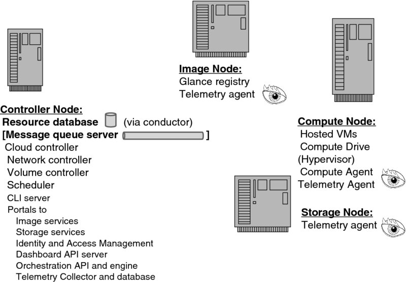
Figure 7.11 Mapping the OpenStack components into a physical architecture: an example.
As far as hypervisors are concerned, OpenStack interworks with several major ones through specific compute drivers, but the degree of interworking varies.67
The compute agent is actually creating and deploying virtual machines. It acts as a server to the scheduler (which we will discuss in the context of the controller node), but it acts as a client when dealing with the central resource database, image node, and storage node, which respectively maintain the Glance image registry and either type (block or object) of storage.
The telemetry agents present in all three nodes collect the performance data used in orchestration, which we will address soon.
Finally, the controller node is at the heart of Cloud management. To begin with, it contains the global resource database,68 which we have already mentioned when introducing the compute agent. Since in practical large-scale deployments this database is replicated, there is a front end (called Nova Conductor), which handles the compute agent interface.
The scheduler is in charge of the placement function.69 It makes the decision on where (i.e., on which compute node) a new virtual machine is to be created and on which storage node a new block storage volume is to be created. The former purpose employs the Nova Scheduler and the latter the Cinder Scheduler.
This takes care of the entities in Figure 7.11, except for the Message Queue Server (which we labeled in brackets). We momentarily defer the discussion of this because—in the rather simplistic deployment example where all controller components are running on the same host—it appears superfluous. Before reviewing the actual means of interaction among the components, we will walk through a simple flow of events resulting in the creation of a virtual machine:
- The flow starts with a remote user invoking the API (more precisely, the Nova API server) in the controller with the request to provision a VM. The controller then requests that the scheduler query the resource database to determine a proper compute node (which is easy in our case since we have only one) and order its compute agent to provision a virtual machine;70
- The compute agent complies with the request, queries the resource database to get the precise information about the image, fetches the image identifier from the image node registry, and, finally, loads the image itself from the storage node, and orders the hypervisor to create a new tenant VM;
- The compute agent passes the information about the new VM back to the controller node and requests that the network controller provide the connectivity information;
- The network controller updates the resource database and completes the network provisioning; and
- Similarly, the compute agent interacts with the volume controller to create the storage volume and attach it to the VM.
Needless to say, to simplify the discussion and to get the basic flow through, we have omitted several essential capabilities. This simple sequence, of course, did not involve orchestration, which would have been unnecessary in this case because (1) the “stack” here contains only one virtual machine rather than an infrastructure of several machines and (2) we assumed that the service offered by the stack does not require auto-scaling or any other service that required monitoring and automatic intervention. Orchestration will get into the picture soon, when we discuss a more complex example.
But the most patent omission is that of all matters of identity and management, including the authentication of the original request and its authorization. We discuss this subject separately in the next section, and we will see that the activities related to identity management permeate all steps.
Now we are ready to clarify further the nature of communications at the application level among various pieces within each OpenStack component. The underlying idea is to have no shared data between any two peers (i.e., a client and a server).71
The OpenStack software has been written with the objective of creating highly-available systems. High availability, an aspect of a broader concept of reliability, is defined in [5] as the “ability of the system to restore correct operation, permitting it to resume providing services during periods when some components have failed.” High availability is achieved through redundancy, by replicating the pieces of a system—in our case, the network, storage, and compute components—that can become single points of failure.
Replicated servers run on a group of machines called a cluster. All these servers together must appear as one server to the client, as illustrated in Figure 7.12. Hence, one of the machines is designated a proxy, which distributes client requests among the rest of the servers and also balances their load. The proxy itself is not a single point of failure, because every other machine in the cluster is ready to take on both the front-end and load-balancing functions.
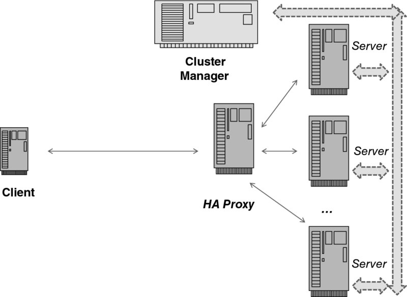
Figure 7.12 A high-availability cluster.
Incidentally, the mechanism we have just described is pertinent to the so-called active–active mode (in which all servers are running at the same time), but it is not the only mechanism to achieve high availability in a cluster. Another mode is active–passive, in which an extra server is kept ready (as a hot standby) but not online, and is brought online in case of failure or overload of the active server. OpenStack supports both modes.
But how does the cluster “know” when to assign the proxy function to another server, or when to bring the hot standby online? For that there is yet another function—the cluster manager. Its job is to observe the health of the cluster, according to its configuration, and reconfigure it in accordance with the circumstances. For this monitoring purpose, OpenStack presently uses software called Pacemaker, which is a product of Cluster Labs.72
By now, it should be clear why no state may be shared between a client and a server. (Suppose the client sends two requests. The first request is directed by the proxy to the top server in Figure 7.12 and the second to the server at the bottom. If the client and the server shared the state, and this state was modified by the first server, the second server would have no way of knowing that the state had changed!)
As we have noted several times, HTTP, the protocol of the World-Wide Web, has been designed exactly with this objective in mind—no state is shared between the HTTP client and the HTTP server. In decades of experience with the World-Wide Web, the industry has learned how to develop and deploy highly efficient servers and proxies. Consequently, it has made a lot of sense to take what was tried and true and apply it—while reusing all the software available—to a new purpose, which is much more general than providing web services.
The computational model here is rather straightforward. An HTTP server is a daemon process (or a thread) that is listening to a specific port. When it gets a message (an HTTP PDU), it parses it and performs a one-time action, which at the beginning was limited to fetching a file and passing it back to the client, but subsequently—as we will see when we address this in detail—has grown much more involved.73 Two different servers may run on the same host or on different hosts—the interface to the services remains the same. It makes sense to combine global management services on a dedicated host, as is the case in our deployment examples.
To this end, all OpenStack modules that have “API” in their names (i.e., nova-api) are daemons providing REST services (discussed in the Appendix). Communications among daemons are carried out via the Advanced Message Queuing Protocol (AMQP).74 The message queue of Figure 7.11 is the structure that enables this.
AMQP can be initiated from either end of the pipe. On the contrary, an HTTP transaction can be initiated only by the client because HTTP is a pure client/server protocol.
There are three aspects to the orchestration in OpenStack. The first aspect deals with the life cycle management specification of a Cloud application (i.e., the stack) and its actual instantiation; the second aspect deals with monitoring the state of the stack on the subject of compliance with specifications for running virtual machines; and the third aspect deals with taking a remediating action. As we mentioned earlier, the Heat component is in charge of the first and third aspects, while Ceilometer takes care of the second.
An early stated objective of Heat was compatibility with the AWS CloudFormation, so as to enable a service already working with the AWS CloudFormation to be ported to OpenStack. (Conversely, a service developed and running in a Cloud employing OpenStack could be moved to AWS; in fact, such a Cloud could burst into AWS.) To this end, OpenStack both recognizes the AWS CloudFormation template and provides the AWS CloudFormation-compatible API.
Over time, the Heat project has developed its own template—appropriately called HOT75—which is actually an acronym for Heat Orchestration Template. The template itself has the same format—and semantics—as the AWS CloudFormation Template, but it is specified in a language called YAML76 rather than JSON. One way or the other, the template is a text file that specifies the infrastructure resources and the relationship among them. The latter feature is programmatic in nature in that it can enforce the order in which virtual machines are created and assigned storage volumes and network connections.
Another programmatic feature is that a template is dynamic: when the template is changed, Heat modifies the service accordingly.
We will start with the description of a computational (i.e., described in terms of computing processes) architecture of the Heat part of the orchestration service architecture depicted in Figure 7.13.
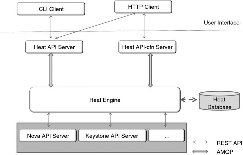
Figure 7.13 The Heat computing architecture.
The Heat engine is the process in charge of launching stacks according to their template specification.
The user interface function is performed by two servers—Heat API and Heat API-cfn—which respectively provide the REST API for the HOT- and AWS CloudFormation-compatible services. Either of these two merely serves as the front end to the Heat engine, with which it communicates over AMQP.
Needless to say, this architecture supports the distribution of processes across available machines in a far more flexible way than our earlier controller architecture picture suggested. All servers of the same type may be replicated and accessed through a high-availability proxy.
In addition to the REST API, the Heat component provides the command-line interface, but the CLI agent converts the commands to the REST API orchestration, so the Heat engine does not deal with CLI directly. The commands are semantically identical to the API in that they refer to the same capabilities. We briefly introduce the commands, in the order they relate to templates, stacks, resources, and the events associated with the resources:
- template-show requests a template for a given stack;
- template-validate requests that a template be validated with specific parameters;
- stack-create requests that a stack be created;
- stack-delete requests that a stack be deleted;
- stack-update requests that the stack be updated (according to the data described in a file, or URL, or with the new values of specific parameters);
- action-suspend and action-resume, respectively, request the name-sake action on the execution of the active stack;
- stack-list requests the list of all user's stacks;
- stack-show requests a description of a given stack;
- resource-list requests the set of resources that belong to a stack;
- resource-metadata requests a resource's metadata attributes;77
- resource-show requests the description of a given resource;
- event-list requests the list of events for the selected resources of the current stack; and
- event-show requests the description of a specific event.
Heat also provides hooks for programmable extensions—the resource plug-in, which extends the base resource class and implements the appropriate handler methods for the above commands.
So far we have addressed the so-called Northern API—the user interface to orchestration. Both API servers act as the front end to the Heat engine. To effect the execution of the commands, the Heat engine, in turn, invokes Southern API—Nova API, Keystone API, and so on. In a nutshell, the sequence of invocations is suggested by an earlier workflow for creating an image.
The remaining piece of the workings of OpenStack orchestration is the mechanisms in support of alarms. An earlier example of a service template in fact refers to the AWS CloudWatch service, which was partly imitated in the earlier releases of Heat. The mechanisms were put in place for users to create and update alarms, along with the mechanisms for reacting to the alarms. For details, and a description of testing with simple but incisive use cases, we recommend Davide Michelino's Summer Student Report78 from CERN.
Later, however, OpenStack decided to deprecate the use of the AWS CloudWatch API and instead rely on Ceilometer. Consequently, this is where the action in OpenStack is at the time of this writing.
To Ceilometer then! As we have mentioned already, its objective is metering—that is, measuring the rate of use of the resources. In the telecommunications business, metering is the first step in the overall charging process, the other steps being rating and billing. To this end, Ceilometer provides the API that a rating engine can use to develop a billing system, but we are not going to be concerned with this matter here. Our main interest—strictly for the purposes of this book—is in using metering to determine when an auto-scaling action is needed.
The task of Ceilometer is much complicated by an obstacle every OSS project had in the past: different parts of a large system invariably use different means for providing management data—and some parts don't provide any data at all. To deal with that, OpenStack had to create several mechanisms where one would have sufficed had the same methodology been used.
The Ceilometer model employs three types of actor: various telemetry agents, the telemetry collector, and the publisher. The collector aggregates data from the agents in charge of each of the five OpenStack components: Compute, Networking, Block Storage, Object Storage, and Image—and then transmits these data to the publisher, which stores it in the database or passes it on to external systems. Having introduced the terminology, we note that, for the purposes of this book, the collector and the publisher are really one entity, which we will call collector. (In the fairly simplistic arrangement of Figure 7.11, the agents are depicted as eyes and are assumed to send their data to the collector by means of notification.)
In an ideal system, each component has an agent that issues event notifications over a unified messaging system (called the Oslo bus). For detail, please consult the respective OpenStack documentation,79 but note that the AMQP is compatible with the Oslo bus, which encompasses other messaging mechanisms. For simplicity, we will assume that all messages are sent over AMQP.
The first—and preferred–mechanism is effected by the Bus listener agent, which processes all notification events and produces the Ceilometer samples. Again, in a system where all components are capable of issuing event notifications, this is the only required mechanism. Absent the uniform notification implementation, the second—less preferred—additional mechanism is in order. Here, a Push agent, which actually creates notifications, needs to be added to every monitored node. And if, for whatever reason, this cannot be done, one reverts to the third mechanism—the Polling agent. The Polling agent does just what its name suggests: it checks remote nodes (via REST API or RPC) in a loop, which includes waiting for a specified interval.80 This is the least preferred method, because its implementation gets in the way of resiliency.
The agents differ in what they do and where they run. (A compute agent runs on a compute host, for example.) A central agent is part of the central management system (the controller node, according to our earlier nomenclature); its responsibilities include accounting for the resources other than compute nodes or instances. The collector, of course, runs on the central management system, too. It should be clear though that there may be several different hosts that run different pieces of the central management system (or, in a high-availability cluster, each of the hosts may run all these pieces). Ceilometer also supports configuration of the agents.
The collected data are stored in the Ceilometer database. Ceilometer provides two sets of API: (1) for writing to the collector and (2) for accessing the database. As with all other components, the API server is a separate process.
The above architecture is summarized in Figure 7.14, which shows a logical message flow. In reality, all the components are “interconnected” by a real messaging bus—that is, they read and write into the same logical “wire.”81
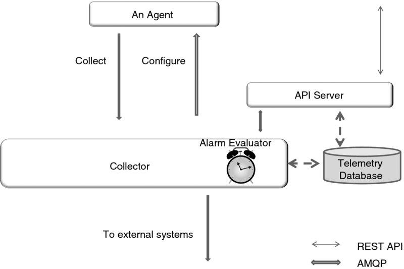
Figure 7.14 The Ceilometer computing architecture.
One other feature of Ceilometer—the one most essential for our purpose—is the ability to create alarms based on pre-defined thresholds (as in “tell me when CPU utilization reaches 70%”). OpenStack defines a separate module for that purpose,82 but for simplicity we consider the alarm evaluator to be part of the collector.
To illustrate the interworking between the telemetry and orchestration proper (i.e., between Ceilometer and Heat), we will use Figure 7.15. We return to the auto-scaling example that we first introduced in the discussion of AWS CloudFormation.
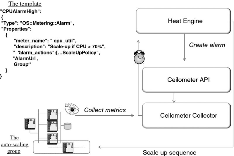
Figure 7.15 Interworking Heat and Ceilometer: an auto-scaling example.
In order to know when to scale up (or down) a stack, the Heat engine needs feedback on the CPU utilization of the stack instances. To enable this, one can define the alarms based on the compute agent's metrics. With the support of Ceilometer, the metrics get evaluated according to the template-specified rules, and exceptions are reported as alarm notifications. (Of course, it is not that Ceilometer itself reads the template—only the Heat engine does. Ceilometer only needs to provide an API flexible enough for the Heat engine to express the template rules for the auto-scaling group.)
In the upper-left-hand corner, part of a HOT template83 is defined to set an alarm based on the CPU utilization of an auto-scaling group. Namely, when the CPU utilization exceeds 70%, the group of servers “scales up,” that is a new server instance is added. A particular property, alarm_actions, is defined in the OpenStack manual as a “list of URLs (webhooks) to invoke when state transitions to alarm. (sic!)” The template also specifies the period to collect the metrics and the statistics used (e.g., average).
The alarm is set on the request of the Heat engine when the stack is created. When the alarm “sounds,” the Heat engine follows up by creating a new instance, connecting it to the networks, and so on. Similarly, an alarm can be set to scale down (say when the average CPU utilization falls below 40%), so when extra instances become redundant, they are eliminated. Note that this feature is not simply an exercise in efficiency by a Cloud provider—it also saves money for the customer, who typically pays the Cloud provider for each instance. A true example of elasticity!
It is important to note that OpenStack supports integration of software configuration and management tools—specifically Chef and Puppet, which we mentioned in the previous section.
We discussed the workflow tools earlier. At the time of this writing, OpenStack is actively working on developing one as part of the Convection project.84 In the project parlance, a workflow is called a Task Flow, and the plan is to offer Task-Flow-as-a-Service (TFaS), similarly to what Amazon AWS has done.
The vision of the service is such that a user would write and register a workflow. An application could then invoke this workflow (and, later, also check its status or terminate it). The orchestrator's job is to react to every change of state in a workflow and invoke the respective tasks.
The service is recursive in that the TFaS can be used by Heat itself to manage its own tasks. For example, a task flow could call Heat API to start a given task. According to this vision, “orchestration is concerned with intelligently creating, organizing, connecting, and coordinating Cloud based resources, which may involve creating a task flow and/or executing tasks.”
Figure 7.16 summarizes the authors' understanding of the OpenStack orchestration vision by combining—and showing the interactions among—the pieces that we have described so far. Again, at the time of this writing this is merely a blueprint for future development.
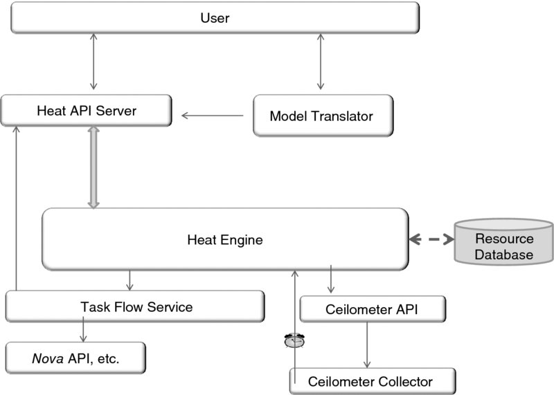
Figure 7.16 Integrated orchestration architecture.
A piece depicted in the upper-right-hand corner is a catch-all for other template specifications (cfn or TOSCA), each of which is interpreted here by an entity called a model translator. We will review some specification examples in the Appendix.
We conclude this section by considering another deployment example—from the networking angle—which is presented in Figure 7.17. This figure modifies Figure 7.11 to demonstrate the structure of a modern node in the Cloud data center. Just as in human anatomy books different layers of a body (e.g., muscles or a skeleton) are shown, here we take a look at a practical way to interconnect the components. To reduce the clutter, we have omitted the image nodes, but all other nodes are present—now replicated and assumed to work in clusters.
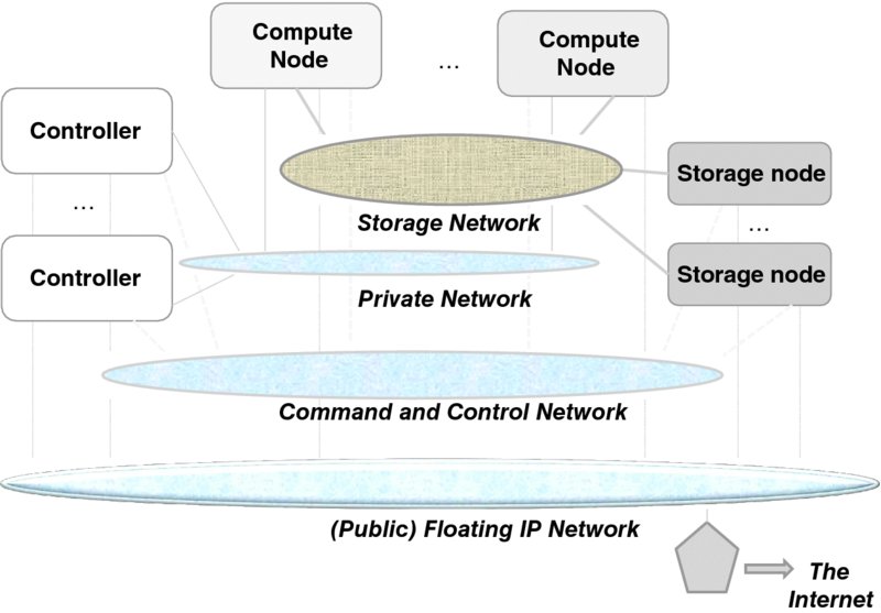
Figure 7.17 Networking with OpenStack nodes.
The following four (Layer-2) networks are completely separate from one another:
- The storage network, which is intended only for accessing storage and thus interconnects only the compute nodes and storage nodes.
- The private network, which exists only for communications among the hosted virtual machines.
- The command and control network, which exists only for the purpose of orchestration and management.
- The public network, which allows connection to the Internet and which, for this reason, employs floating IP addresses as discussed before.
Having these networks separate is more or less typical85—both for security purposes and for differentiating the capacity, as different purposes have different bandwidth demands. As a minimum, the private, public, and command and control networks are advisable.
7.4 Identity and Access Management
The discipline of Identity and Access Management (IAM) deals with matters of authentication and authorization. Both are indispensible to Cloud Computing: before applying any operation to a virtual machine (or a stack) throughout its life cycle, the management and orchestration system must know who is requesting the operation and whether the requesting entity has the right to the operation.
The need for the IAM is pervasive, and it is manifest in other contexts. Each machine—whether physical or virtual—needs to have its own IAM mechanisms (part of the operating system) to control access to programs and data. An application may further have its own IAM to control access to its services. The IAM functions at different contexts are hierarchical in terms of privilege; the one associated with the Cloud management system is most privileged. This resembles the administrative privilege hierarchy of a virtualized host, as shown in Figure 7.18. We will explain further the reason for the privilege hierarchy later; for the moment, let us recall Chapter 3, which introduced the concept of privilege levels and protection rings.
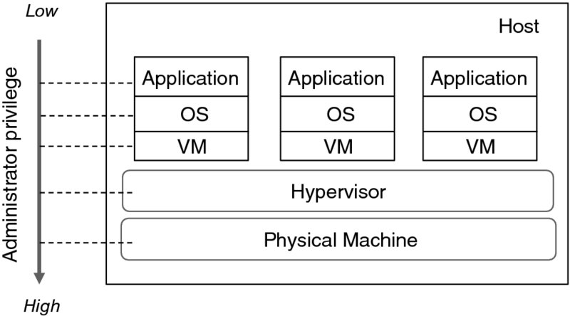
Figure 7.18 Relative administrative privilege.
Figure 7.19 summarizes what falls in the realm of IAM generally. In short, it deals with the life cycle and correlation of the identity information representing different personas that correspond to an entity, and the authentication and authorization of the entity. The construct through which an entity can be consistently and comprehensively identified as unique is known as an identity. An identity may be associated with a person, project, process, device, or data object.
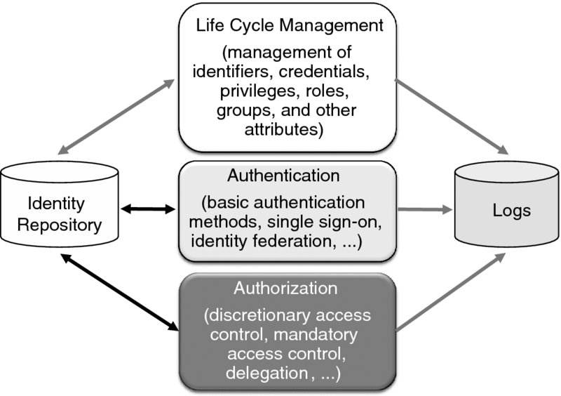
Figure 7.19 Scope of identity and access management.
We define the identity as a structure that combines the entity name (identifier)86 and the credentials for authenticating the entity. Creating an identity for a given entity requires proof of credentials, role setting, and provisioning of the associated data (including privileges) in the repository. Naturally, adequate security and privacy controls must be in place to protect all the identity-related information created. To this end, it is necessary to have a clear policy on how such information is used, stored, and propagated among systems. Such a policy may be provider specific or it may be dictated by governmental regulations (e.g., the Sarbanes–Oxley Act in the United States). To enable auditing and reporting of policy compliance, critical IAM activities (both online and offline) must be logged. Auditing trails of who used the system and which authorization decisions were made is also essential for incident management and forensics.
In this section, we will first discuss the implications of Cloud Computing as related to identity and access management. Then we will discuss the most pertinent state-of-the-art IAM technology by reviewing its building blocks. Here we just provide an outline, and leave the details to the Appendix. Finally, as a case study, we will examine Keystone, the OpenStack component that implements identity and access management.
7.4.1 Implications of Cloud Computing
To help us understand the implications of Cloud Computing, let us consider a flow for creating a virtual machine through a web-based portal. Let Alice be a user of the portal.87 The flow is as follows.
First, Alice attempts to access the portal, which sets off an authentication and authorization step. Alice provides her credentials.
At this point the portal authenticates Alice and determines her entitlements. But being a user interface, it relies on another Cloud component (i.e., the identity controller) to do so. The portal invokes the identity controller through an identity API. Upon successful authentication and authorization, Alice is presented with the services and resources to which she is entitled. Next, using the portal, Alice asks to provision a virtual machine with certain properties. This triggers a chain of actions on behalf of Alice across various components:
- The portal constructs and sends a request to the compute controller through a compute API. The request includes her credentials.
- The compute controller validates the credentials.88 If everything goes well, it allocates a compute node and orders the compute agent therein to provision a virtual machine.
- Upon receiving the order, the compute agent proceeds in requesting the image from the image store through an image API. The request includes Alice's authorization. If the authorization is valid, the image is downloaded. Then the hypervisor creates a new virtual machine.
- After the virtual machine is created, the compute agent requests (via the networking API) that the network controller provision the specified connectivity. The request includes confirmation of Alice's authorization in a form that the network controller can check.
- Upon successful validation of the authorization, the network controller allocates the networking resources and returns the related information to the compute agent.
- The compute agent asks the volume controller to create the required volume and attach it to the virtual machine through a block storage API.
- The volume controller allocates the volume and returns the related information to the compute agent. (Of course, this step also required authorization checking.)
Now Alice is notified that her virtual machine has been provisioned, together with the related information (e.g., an IP address and a root password) for accessing it.
From the above flow,89 we can make the following five observations:
- The portal is accessible to authenticated users only. So the first time Alice tries to have access, she has to log on, providing her credentials as dictated by the user interface. The specific credentials required depend on the authentication method supported by the Cloud service.
- After Alice has logged on, the authentication and authorization steps repeat several times. Specifically, verification of Alice's privilege is in order whenever an API request is involved. The need for repeated authentication and authorization is understandable. Normally, the effect of authentication and authorization is limited to an API transaction and to the involved components in a distributed system. The need is further compounded by the objective of sharing no state in support of “massive scalability.”
- Alice is not required to provide her credentials every time they are needed. This is an important design matter, which is addressed by implementing single sign-on. As a result, additional interactions requiring her credentials after Alice has logged on can be handled without her intervention.
- There is a need for a delegation mechanism to allow Cloud service components to act on behalf of Alice. Obviously, replicating Alice's original credentials across the distributed components is unacceptable (imagine giving your password to everyone whom you delegate any task to). A viable mechanism should use a temporary construct in lieu of Alice's original credentials. Needless to say, it is imperative that the construct have at least as good security properties as Alice's original credentials. However strange this requirement may look now, we will demonstrate (see the Appendix) that it can be fulfilled.
- Beside Alice, there are other privileged users, such as Cloud administrators or process owners. They are subject to authentication and authorization as well.
The complexity of the matter increases as soon as automation, a hallmark of Cloud Computing, comes into the picture. Consider, for example, auto-scaling. As we have seen, an orchestrator is responsible for creating a new virtual machine in response to a certain alarm. Such an alarm is typically triggered when the load of an existing virtual machine reaches a pre-set threshold. The flow for creating a virtual machine is pretty much the same as that involving Alice directly. The major difference here is that it is the orchestrator rather than the portal that constructs and sends a request to the compute controller through a compute API. The orchestrator acts on behalf of Alice. It gets the specification of the virtual machine from a template that she has provided beforehand. As before, to do what is necessary, the orchestrator will need to include Alice's authorization in the request to the compute controller. As before, the orchestrator should use a construct in lieu of Alice's original credentials and the construct should be valid for a short period of time.
But here lies a problem. The timing of scale-out alarms is unpredictable. It is quite likely that when an alarm does go off, an existing temporary construct has already expired. Therefore, it is necessary that the orchestrator obtain a fresh temporary construct dynamically—on demand.
Moreover, auto-scaling is not just about provisioning and starting a new virtual machine. The reason for having a virtual machine to begin with is to run applications. Once the virtual machine is up and running, the orchestrator also needs to install applications remotely, provision the application-specific data (e.g., credentials of application users and the administrator), configure the system and applications, and finally launch the applications. To carry out these tasks, the orchestrator needs to have access to application-specific data (i.e., metadata) pre-provisioned in the Cloud. And then there is a need to run scripts on the virtual machine, which may require special privileges. Fortunately, the orchestrator could do all of this, given proper permissions from Alice.
But that creates another problem. For one thing, the orchestrator must have special privileges on Alice's virtual machine. Therefore, it is essential that Alice be able to delegate roles with enough granularity to mitigate potential security risks. In addition, since the orchestrator assumes whatever power the special user has on the virtual machine, the privilege assigned to the special user shall be the bare minimum required for performing the tasks at hand.
Overall, Cloud administrators have privileges that may be abused. Thus, in a Cloud environment it is essential to have in place the controls that can limit the potential damage.
7.4.2 Authentication
When it comes to authenticating a person to a computer system, there are three common types of credential, as shown in Figure 7.20. Alice may be authenticated based on what she knows (e.g., a password), what she has (e.g., a hardware security token), or what she is (e.g., her fingerprint). Obviously, authentication based on what Alice knows is the simplest method as it requires no additional gadgets. This explains why passwords are used most widely.
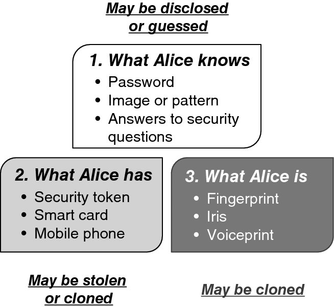
Figure 7.20 Credentials for user authentication.
The choice of an authentication method depends on the risk that can be tolerated. Obviously, the more privileged a user is, the stronger the authentication method should be. Just imagine the havoc that an adversary masquerading as a Cloud administrator could cause! Authentication based on more than one type of credentials (called multi-factor authentication) can significantly increase the level of assurance. Given the various privileged users involved, it makes sense for a Cloud infrastructure service to support at least two-factor authentication. The most common form of two-factor authentication combines a password (i.e., what Alice knows) and a dynamically generated code retrievable from a device (i.e., what Alice has).
In the presence of networking, it is necessary to use a cryptographic system. Any such system either uses shared secrets (symmetric cryptography) or relies on public-key cryptography.
The latter requires a pair of keys: one is known as the public key, which can be shared, and the other is known as the private key, which must be kept secret. Given a properly generated public key, it is computationally infeasible to derive the respective private key. A well-known and widely used public-key cryptographic system is RSA, which was developed at MIT in 1977 by Rivest, Shamir, and Adleman (hence the acronym) [23]. The property that it is computationally infeasible to derive the private key from the public key is based on the intractability of factoring a large number. One important feature of RSA is that the public- and private-key operations are commutative: a quantity encrypted with the private key can be decrypted with the public key. This feature allows us to use the scheme not only for secrecy, but also for signatures and authentication.
Figure 7.21 illustrates the application of public-key cryptography to authentication. As shown, Alice announces herself. Upon receiving Alice's message, the authenticating system sends her a challenge R, which is typically a combination of a random number and a time stamp. Alice responds with PrKA(R), which is the challenge encrypted in her private key PrKA. The system then decrypts PrKA(R) using Alice's public key. If the decrypted quantity is the same as the original challenge, the authentication has been successful. It goes without saying that availability of Alice's public key to the computer system is assumed. (How this is achieved is another matter, which we will discuss later.)
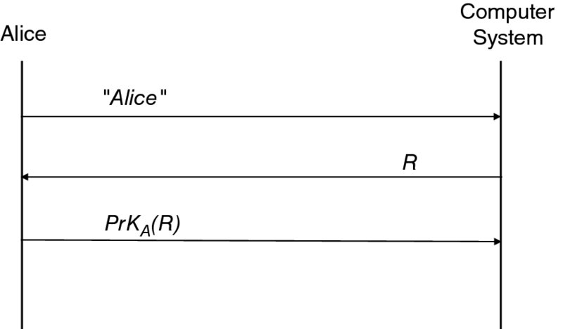
Figure 7.21 Public-key-based authentication (a simplified view).
An important nuance here is that the key pair for authentication must be limited to that specific purpose only and not be used for signing as well. Signing involves the same operations as authentication, namely encrypting a document or its digest with Alice's private key, which can then be decrypted and verified by anyone else with her public key. If the same key is used for authentication and signing, it is possible to trick Alice into signing, for instance, an IOU by presenting it as a challenge—as shown in Figure 7.21.
Not only must the key pairs be different for the authentication and signing tasks, but the procedures for key generation and management need to be different, too. While private keys used for authentication and decryption may be escrowed (i.e., placed in a trusted third party's care), certain jurisdictions forbid key escrow of private keys used for digital signatures.90 In Cloud Computing, keys are effectively escrowed, since privileged Cloud administrators can access stored private keys. Key escrow is problematic for regulatory compliance. To meet such requirements, a hardware security module—a piece of storage equipment that has a separate administrative interface from that of the hypervisor—is often used.
With public-key cryptography, there is a need for storing the private key on the one hand and for distributing the public key securely (i.e., proving the association of Alice and her public key) on the other hand. The former problem is somewhat simpler as it can be solved by the use of specialized devices, such as a smart card. The latter problem, however, has been a challenge since the time of the first known publication on public-key cryptography by Whitfield Diffie and Martin E. Hellman [24]. Ultimately, the industry Public Key Infrastructure (PKI) solution called for a management infrastructure in support of:
- Issuing a PKI certificate that binds a public key to an identity along with a set of attributes.
- Maintaining a database of the certificates.
- Specifying mechanisms for verifying certificates.
- Specifying mechanisms for revoking certificates (which includes storing them, too).
In this solution certificates serve as credentials. Loren Kohnfelder introduced some of its central elements in his Bachelor thesis [25] in 1978 at MIT, including the construct of a certificate, the idea of using the digital signature of a trusted authority (or Certification Authority (CA)) to seal binding, and the notion of certificate revocation. Naturally, a certificate should have a limited lifetime. This, however, is not good enough. While a certificate remains valid, things could go wrong to invalidate the binding. For example, an adversary could get hold of the private key. Certificate revocation allows a CA to void a certificate.
The use of a CA's signature to bind a public key to an identity gives rise to the question of how the signature is verified. If the signing algorithm is based on public-key cryptography, the question is the same as that of public-key distribution. So it can be solved by the same method: a CA is issued a certificate by another CA of a higher rank. The step can be repeated as many times as needed, resulting in a chain of certificates (or a chain of trust). Figure 7.22 shows a chain of trust conceptually. At the top of the chain necessarily is a trust anchor with a root certificate that is self-signed. Given that anyone can generate a key pair and a self-signed certificate, such trust anchors must be well-known and few. The hierarchical certification model has been standardized by ISO and ITU-T, which published Recommendation ITU-T X.509 [26]. An X.509 certificate captures, among other things, the holder's name and public key, the issuing CA's name and signature, the signature algorithm, the expiration time, and the issuing CA's certificate. Although there are other standards for certificate formats, X.509 is the most widely used. Part of its success is due to its built-in extensibility. Other organizations, notably the IETF, have specified extensions.
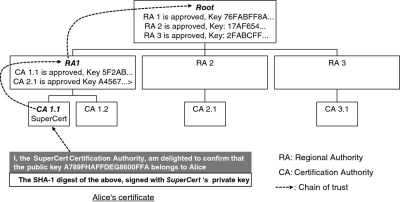
Figure 7.22 Conceptual illustration of the chain of trust.
We would like to emphasize that web security depends on this standard: the TLS protocol uses X.509 certificates for server authentication.91 Naturally, the X.509 dependency is carried over to Cloud Computing. The dependency is, in fact, stronger, because certificates are used not only for server but also client authentication.92
Public-key cryptography may be used without a PKI. A case in point is the SSH protocol, which is indispensible in Cloud Computing. (For one thing, SSH is the primary secure means for automated access to a virtual machine.) As specified in RFC 425293 and RFC 4253,94 SSH supports the use of certificates for client and server authentication.
One problem with the SSH standard is that it has introduced multiple options. While the use of certificates is supported, it is not mandatory, and that results in rather problematic deployment scenarios. In particular, the server may send just the public key and a hash (also known as a fingerprint) of the key upon a connection request. The client may accept the public key blindly when first receiving it. Such a trust-on-first-use approach is subject to nasty attacks, but it is still practiced.
Our opinion is that in Cloud Computing, this practice has to change. A logical solution would be to mandate the use of certificates for both the client and server authentication. Unfortunately, this is impractical to date. Open-source software underpins Cloud Computing, but the certificate formats implemented in open-source SSH software (including OpenSSH,95 which is bundled with all Linux distributions) are proprietary. Best practice is to keep a copy of the hash in a secure data store (such as the DNS, defined in RFC 425596) that can be queried by the client during its very first contact with the server. The client verifies the fingerprint received from the server against that in the secure store and proceeds with the connection only if the fingerprints match.
7.4.3 Access Control
One way to keep track of who is authorized to access what is by maintaining a table (called an access control matrix) where the rows correspond to subjects and the columns correspond to data objects. The matrix reflects the protection state of a system. A subject is an active entity (e.g., a user or process), while an object is a passive one (e.g., a file). Each entry in the matrix (denoted Aij) specifies the rights (such as read or write access) to a given object (denoted Oj) that a subject (denoted Si) has. Figure 7.23 shows such a matrix, where subject 2 is least privileged, with access rights to only object 1 and object 2. In comparison subject 1 is more privileged, with access rights to all objects. In fact, subject 1 could be a system administrator. He only has read access to object 3 (say payroll data) and object 4 (say auditing trail) because of the least-privilege principle. These objects are readable and writable by subject 3 (which could very well be a process). The matrix provides a powerful model for designing access control systems and determining whether a system is secure [27].
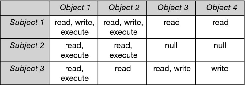
Figure 7.23 Access control matrix.
The access control matrix is naturally sparse and so it requires special implementation considerations. In a nutshell, only non-empty matrix elements need to be stored, but their positions need to be recorded. Two common approaches are storing relevant cells by columns and rows, respectively. The column approach yields the Access Control List (ACL), and the row approach yields the capability list. We discuss these in more detail in the Appendix.
Access control can be either discretionary or non-discretionary, depending on who has the authority to set rights to an object. With Discretionary Access Control (DAC), the owner of an object may change the permissions for that object at will. DAC is implemented in most operating systems using access control lists. Under the scheme, an owner can revoke the rights, partially or fully, to an object given to any subject with particular ease. The owner just deletes the subject's rights in question from the object's access control list. Nevertheless, access control lists have limitations. Notably, they are unsuitable for handling cases where a user needs to delegate certain authority to another user for a period of time. Needless to say, dynamic delegation (which is essential in the Cloud Computing environment) has to rely on a separate mechanism.
The multitude of access control lists in a normal system also makes it difficult to ascertain privileges on a per-user basis. This is problematic when user privileges need to be updated quickly to reflect a sudden change of personnel or an incident. The use of the group construct adds another wrinkle. An access control list could contain both a user and a group to which the user belongs. If the user's right is revoked, but the group's right is not, the user can still access the object. Clearly, there is room for improvement!
In non-discretionary access control, a subject may not change the permissions for an object, even if the subject creates the object. The authority that can do so exists at a system level. Mandatory Access Control (MAC) is an example of restricting the flow of information between personnel of different ranks in military and civilian government agencies. MAC typically requires that every subject—as well as every object in a computer system—be assigned a security level within a hierarchy by a system-wide authority, according to a policy. Access eligibility is based on the dominance relation between the assigned security levels of the subject and the object. A subject can access an object if and only if the object is at the same or a lower level in the hierarchy. In the US military, for example, information is classified into Top Secret, Secret, Confidential, or Unclassified. In order to access information classified as Secret, a staff member must have an equivalent or higher security clearance level. Such a scheme assumes the use of a Trusted Computing Base (TCB) to enforce the policy over all subjects and objects under its control.
The first publication [28] on trusted computer system evaluation criteria (called the Orange Book, because of the color of its cover) from the US Department of Defense in the 1980s expressly defines MAC as “a means of restricting access to objects based on the sensitivity (as represented by a label) of the information contained in the objects and the formal authorization (i.e., clearance) of subjects to access information of such sensitivity.” The definition is based on the Bell–LaPadula model [29], which has influenced the development of much computer security technology. The resulting systems are called multi-level security systems, because of the multiple security levels used in the model.
The Bell–LaPadula model essentially addresses control of information flow through the policy of no “read up” or “write down.” Enforcement of the policy guarantees that information never flows downward. A useful outcome is protection against Trojan horse malware. Consider a scenario where Alice, a privileged user, ends up running an infected program. Without MAC, the associated process could access the file keeping personnel salary information in her organization (which is inaccessible to her adversary Andy), and write its content to another file (named “salary2,” for example) accessible to Andy. With MAC, the process cannot write to salary2 at a security level lower than that of Alice; and if salary2 is at a high security level, Andy cannot read it.
The Bell–LaPadula model inspired the Biba model [30], which addresses the integrity of classified information. Specifically, the Biba model prescribes the policy of “read up” and “write down”, which is actually forbidden by the Bell_LaPadula model. The rationale is that the integrity of an object can only be as good as the integrity of the least-trustworthy object among those contributing to its content. The Bell–LaPadula model also spurred many other developments to address its limitations. Of particular relevance to Cloud Computing are two important developments: type enforcement and Role-Based Access Control (RBAC), described below.
Type enforcement [31] is due to E. Boebert and D. Kain. According to [32], the idea was triggered by the problem of verifying that a multi-level security system meets the requirement that sensitivity levels be accurately included in printed output. Apparently a solution component involves the use of pipelines. The TE approach essentially addresses the inability to enforce pipelines in the Biba model. Consider an application for sending data over a network confidentially. A pipeline in this case would consist of a process preparing the original data (P1), an intermediate process to encrypt the data (P2), and a process for handling network transmission (P3). The read-high policy can ensure the integrity of the data flow but cannot enforce the pipeline structure. In other words, any data readable by P2 is also readable by P3 as well. Yet P2 could be bypassed and clear-text data could be transmitted to the network.
With type enforcement, each object is assigned a type attribute, and each subject a domain attribute. Whether a subject may access an object is governed by a centralized table called the Domain Definition Table (DDT) that has been pre-provisioned. The table includes, conceptually, a row for each type and a column for each domain. The entry at the intersection of a row and column specifies the maximum access permissions that a subject in that domain may have to an object of that type. The table, in effect, is another access matrix. It is checked whenever a subject seeks access to an object. Access is denied if the attempted access mode is not in the table. Type enforcement was later extended by L. Badger et al. [33] to become Domain and Type Enforcement (DTE), which introduces a high-level language for access control configuration and implicit typing of files based on their positions in the file hierarchy. TE and DTE are more general than traditional multi-level security schemes. They can enforce not only information flow confidentiality and integrity, but also assured pipelines and security kernels.
A prominent implementation of mandatory access control is the SELinux kernel extension to Linux based on the Flask effort97 at the US National Security Agency (NSA). In addition to multi-level security and type enforcement, SELinux also supports multi-category security. So-called categories add another dimension to control. A category is a set of subjects that have equal rights according to a given policy. For instance, the category assignments and a policy could be such that two subjects, a and b, which belong to category X, may be allowed to communicate with each other and with subjects in the category X′, but no subject in category X may communicate with a subject in category Y.
As far as implementation is concerned, categories are represented by their respective identifiers or labels. A central authority assigns a subject to a category, by associating the subject with a respective label. The same procedure is carried out for the objects. With all other policies in place, the category-based policies provide an additional and independent set of controls.
SELinux underpins the sVirt service, aimed at enforcing virtual machine isolation. With sVirt, each VM is assigned, among other things, a unique label.98 In addition, the same label is assigned to the resources (e.g., files and devices) associated with the virtual machine. Isolation of virtual machines is assured by forbidding a process to access a resource of a different label. If the hypervisor is implemented correctly, a virtual machine may not access the resources (such as the disk image file) of another machine. But no practical hypervisors can be proved secure and bug free. In light of the situation, sVirt adds extra protection.
The US NIST spearheaded the development of the role-based access control technology. (A comprehensive monograph [34] on RBAC, among other useful information, provides a detailed history, dating back to the invention of the cash register in 1879.) RBAC has its roots in the enterprise, where each individual has a well-defined function (or role), which, in turn, defines the resources the individual is authorized to access. As [34] reports, NIST first began studying access control in both commercial and government organizations in 1992, and concluded that there were critical gaps in technology. They specifically found that there was no implementation support for subject-based security policies and access based on the principle of least privilege.
To address these problems, [35] proposed the initial RBAC model, which was subsequently named—after its authors—the Ferraiolo–Kuhn model. This model formally defines the role hierarchies, subject–role activation, and subject–object mediation as well as their constraints, using set-theoretic constructs. At its center are three rules concerning (1) role assignment, (2) role authorization, and (3) transaction authorization. The first rule postulates that a subject can execute a transaction only if it has been assigned a role, which then, according to the second rule, must be authorized for the subject. In addition, according to the third rule, the transaction itself must be authorized. In other words, access to any resource can take place only through a role, which is defined by a set of permissions. (In contrast to the case of ACLs, removing a subject's role immediately disables the subject's access to a resource.) Another important feature of the model is that roles are hierarchical rather than flat (as is the case with ACL groups), and they can be inherited. The feature eases aggregation of permissions among roles. For instance, permissions assigned to a junior manager can be aggregated and assigned to a senior manager. Another important feature is that constraints (in the form of policy rules rooted in separation of duty99 and least privilege) can be used to enforce high-level security goals, such as preventing conflicts of interest. For instance, policy rules can be defined to prevent a user from being assigned or activating simultaneously two conflicting roles (say system administrator and auditor).
Following the original proposal, RBAC research mushroomed both in the USA and internationally, and its applications began to emerge in areas such as banking, workflow management, and health care. By the end of 2003, the industry had formed a consensus on the ANSI RBAC standard [36]. The standard has been widely accepted as the basis for national regulations. For instance, the US Health Insurance Portability and Accountability Act (HIPAA) prescribes the use of RBAC specifically. It is also worth noting that before the advent of RBAC, an access control model was considered either mandatory or discretionary. RBAC changes that view. Providing a flexible policy framework but no specific policies, it can support both discretionary and mandatory access control [37].
7.4.4 Dynamic Delegation
Dynamic delegation is a relatively new development. Traditional identity and access management systems can handle delegation that is set up beforehand (but never on the fly). Consider the following proverbial use case originated on the Web. Alice stores her photos at the website TonVisage.com, run by the company TonVisage. Access to these photos is password-protected. Only Alice knows her password, and she wants to keep it that way. But now Alice wants to print her photos—taken during a-once-in-a-lifetime trip to the Himalayas, and make a real, physical album. To achieve this, she plans to use a printing service offered by PrintYerFace.com, which promises, for a relatively small price, to edit Alice's photos professionally and print them on beautiful thick paper bound in an album. How can PrintYerFace get Alice's photos? Alice certainly does not want to divulge her TonVisage login and password to anyone. Perhaps she could be asked to mail her photos in. This, however, would be an inconvenience to her. It would also be a burden to TonVisage given the storage space needed for the photos and the company's business plan for adding a million users each year. In addition, the competition is there: Alice, for instance, can put her photos on a stick and walk to a local print shop. Commonsense dictates that things should be made as simple as possible for Alice: a temporary permission for reading her photos of the Himalayas at TonVisage.com is all that she should pass to PrintYerFace.
To support the use case, the OAuth community effort100 developed the initial open solution in 2007. It's not that a solution didn't exist; there were actually, too many proprietary solutions employed by the so-called Web 2.0 companies such as Google, AOL, Yahoo!, and Flickr. The solution (known as OAuth 1.0) was later brought to the IETF and became the basis of OAuth 2.0, the formal standard developed eventually under a specifically chartered working group there.101 The OAuth effort in the IETF attracted much interest. The Web 2.0 companies participating in the community work were soon joined by network equipment vendors and major telecommunications providers. Over time, new applications far more serious than printing of photographs have emerged, in particular automated management of virtual machine life cycles in Cloud Computing.
The first OAuth output of the IETF is an informational RFC on OAuth 1.0.102 Although not an official standard, it was intended as an implementation specification and it has been used as such. The RFC differs from the original community specification chiefly in that it has addressed some security problems by making TLS mandatory in cases where it is necessary, clarifying the use of time stamps and other nonces, and improving cryptographic signatures.
Getting back to Alice's use case, Figure 7.24 shows conceptually how TonVisage can obtain her permission to gain access to her photos based on OAuth 1.0. The initial request from Alice to PrintYerFace to print her album was not part of the standard exchange (because the request itself did not need any new standardization), which is why we assign it a sequence number of zero. On receiving her request, PrintYerFace, in turn, requests access to Alice's photo album at TonVisage in message 1. Now TonVisage needs to obtain Alice's permission to actually pass the album to PrintYerFace, which is achieved by exchanging messages 2 and 3.
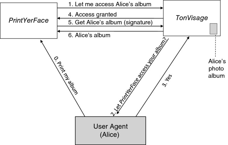
Figure 7.24 Conceptual OAuth 1.0 workflow.
There are two major issues here, as far as the authentication of the subjects involved is concerned: first, TonVisage needs to understand that messages 2 and 3 are part of the conversation with Alice (and not someone impersonating her); second, TonVisage must know that it is actually receiving a request from and releasing information to PrintYerFace. The first issue is dealt with simply by authenticating Alice by her password with TonVisage. The second issue is addressed by having TonVisage and PrintYerFace share a set of long- and short-term cryptographic secrets. A long-term shared secret allows PrintYerFace to authenticate to TonVisage; a short-term shared secret allows PrintYerFace to prove that it has proper authorization. Dynamically generated by TonVisage, the short-term secret is returned to PrintYerFace in message 4. Using a combination of the long- and short-term secrets to sign its request for Alice's album, PrintYerFace can finally get the album as shown in messages 5 and 6.
The OAuth 1.0 scheme, however, has drawbacks. For one thing, PrintYerFace (i.e., the client in the OAuth 1.0 jargon) needs to acquire different kinds of long-term and temporary credentials and use a combination of them to generate signatures. This proves, too complex to be implemented correctly by web application developers. In addition, OAuth 1.0 leaves much to implementations; the specification still warns of a legion of potential catastrophes that sloppy implementations may engender. For one thing, the confidentiality of the requests is not provided by the protocol, and so the requests can be seen by eavesdroppers. In addition, if TonVisage (i.e., the server in the OAuth 1.0 terminology) is not properly authenticated, transactions can be hijacked. Furthermore, to compute signatures, the shared secrets used for signing must be available to OAuth code in plain text. This requirement is, unfortunately, too easy to implement by storing the secrets in plain text on servers. If this is done, an attacker who breaks into the server will be able to perform any action by masquerading as the clients whose shared secrets are obtained in the attack.
If this were not enough, more potential problems arise because the actual OAuth code on the client host typically belongs to a third party. This can be mitigated if the server uses several factors in authentication, but again it is not part of the protocol specification, it's just something a “smart” server should do. The proverbial phishing attack is yet another evil that can be overcome only by users who now need to be “smart” to understand what sites they are dealing with. Other security problems have to do with the length of secrets and their time-to-live. Again, without confidentiality, eavesdroppers can collect authenticated requests and signatures and then mount an offline attack to recover the secrets.
These are by no means all known security problems, but it should be clear by now why OAuth 1.0 needed a serious follow-up. A new framework and protocol can not only address security problems but also support new use cases, such as automated life cycle management of virtual machines. New use cases entail new requirements, in particular the flexibility to use a separate, dedicated server to handle authentication and authority delegation. Because of the requirement, the OAuth 2.0 framework as specified in IETF RFC 6749103 includes four actors. In addition to the resource owner (e.g., Alice), client, and server employed in OAuth 1.0, another server specific to authorization is introduced. The new server naturally is called the authorization server, while the original server is qualified as the resource server. The introduction of the authorization server has actually been motivated by Cloud Computing, which may involve multiple resource servers that rely on the same authorization server. The authorization server provides services through service endpoints in terms of the Uniform Resource Identifiers (URIs).
Figure 7.25 shows conceptually the OAuth 2.0 workflow for the same use case. It is similar to the OAuth 1.0 workflow, especially if TonVisage also serves as the authorization server. The major difference lies in how PrintYerFace proves that it has Alice's authorization. Instead of providing a signature as in the case of OAuth 1.0, PrintYerFace shows an access token issued by the authorization server. The token represents a set of temporary rights. Moreover, it may not be bound to a particular client. Such an access token is known as a bearer token. The holder of a valid bearer token may access the associated resources by providing the token alone. An analogy here is a concert ticket. It is thus essential that the bearer tokens be properly protected, both in motion and at rest. Making the tokens as short-lived as possible, of course, helps contain any damage caused by disclosure.
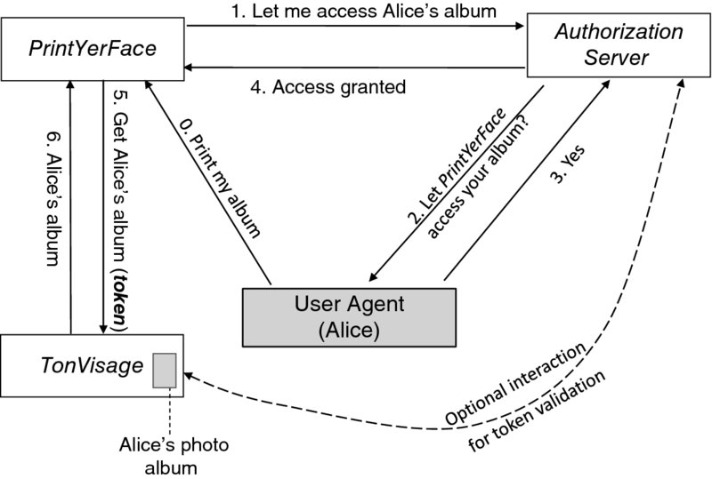
Figure 7.25 OAuth 2.0 conceptual workflow.
Obviously, upon receiving a resource request, the resource server must validate the access token included and ensure that (a) it has not expired and (b) its scope covers the requested resource. How the resource server validates the access token is outside the scope of OAuth 2.0. We can, however, observe that there are two options for where token validation is actually done:
- Resource server. In this case, the token needs to be in a standard format and capture verifiable information. A standard is the JSON Web Token (JWT)104 specification from the IETF. The JWT representation is particularly compact, which allows so-represented access tokens to be carried within HTTP authorization headers or URI query parameters. (The latter option is not recommended though; the URI parameters are likely to be logged.) The representation also allows critical information to be signed and encrypted.
- Authorization server. In this case, the token format is dictated by the authorization server since it is responsible for both issuance and validation of access tokens. The authorization server may provide the token validation service through a specific endpoint.
Both options are relevant to Cloud Computing, and we will return to them later in the case study of OpenStack Keystone.
7.4.5 Identity Federation
Identity federation, first introduced in the enterprise and web industries, allows a user to gain access to applications in different administrative domains without using domain-specific credentials or explicit re-authentication. This is achieved primarily by separating the identity management component from each application and outsourcing it to a general Identity Provider (IdP). The resulting distributed architecture entails the establishment of trust between the application provider and the IdP, and trust between the user and the IdP. An application can then rely on the IdP to verify the credentials of a user, who, in turn, can enjoy the convenience of fewer credentials and single sign-on. In the nomenclature of identity federation, the user is known as the principal (or claimant or subject) and application the relying party.
An essential requirement here is that multiple service providers use a common set of mechanisms to discover the identities of users, relying parties, and identity providers. It is also essential that sensitive information exchanged among these entities, and possibly across multiple domains, be secure (e.g., that confidentiality and integrity are protected). Several mechanisms in support of identity federation exist. In the Appendix, we will review three mechanisms of particular importance: the Security Assertion Markup Language (SAML), OpenID,105 and OpenID Connect106 (which is actually an application of OAuth 2.0).
7.4.6 OpenStack Keystone (A Case Study)
Keystone is the gatekeeper of OpenStack services, providing centralized authentication and authorization. Not only virtual machine users but also OpenStack services are subject to its control. It provides core services called the identity service and the token service.
The identity service handles basic authentication of users and management of the related data. A user may be a person or a process. User authentication based on passwords is supported natively, but it is possible to use other authentication methods through external plug-ins. In addition to the user, Keystone supports the constructs of domain, project, group, and role. The first three constructs have to do with the organization of personnel and resources, with domain at the highest level. Accordingly, a project, which encapsulates a set of OpenStack resources, must belong to exactly one domain. Similarly, a group, which is made up of users, must belong to exactly one domain. The role construct is a different story. Representing a set of rights, it provides the basis for access control. A user must have a role assigned in order to access a resource, and the role is always assigned on a project or domain. Keystone uses a single namespace for roles. A well-known role is admin. When it comes to users, the identity service also supports identity federation to allow an organization to reuse its existing identity management system, saving the need for provisioning in Keystone the existing users of the organization. Keystone has the flexibility to support multiple identity federation protocols, such as SAML 2.0 and OpenID Connect. Support for SAML 2.0 is already available.
Central to the token service is the notion of a token. Figure 7.26 shows a simplified workflow to illustrate its function. Again, we consider the case of provisioning a virtual machine. The user is authenticated by Keystone first before gaining access to Nova or another service. Upon successful authentication, the user is given a temporary token that denotes a set of rights. From this point on, to get a service, the user (or rather the user agent Horizon) encloses the token in the service request. The user can receive the service only if the token is validated and the rights represented by the token comply with the access policy of the service. If the token has expired, the user can obtain a new token and try to get the service again.
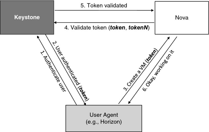
Figure 7.26 A simplified workflow for VM provisioning.
As shown in Figure 7.26, Nova asks Keystone to validate the token as Keystone is responsible for both token generation and token validation. This is not the only way to do things though. We will discuss another approach and the trade-offs later. For now, it is important to note that when asking Keystone to validate the user token, Nova (or any other service) also needs to provide its own token (denoted tokenN in the figure) to authenticate itself. Nova acquires a token the same way as an end user does. It needs to pass authentication. But there is a difference. Nova cannot enter the password or other types of credential interactively as a human being. It can only retrieve its credentials stored at a pre-set location. The simplest solution is to keep the credentials in a file. Indeed, this is what is done throughout OpenStack as a default. In the case of Nova, there is a specific configuration file and the password for authentication to Keystone is there in plain text! We will discuss the basic mechanism for storing passwords in the Appendix. The mechanism shields passwords from even the most privileged administrator (i.e., root). But it works only when the authentication process is interactive.
To provision a virtual machine, Nova actually needs services from other OpenStack components. The additional steps are shown in Figure 7.27. Glance keeps a registry of images (including the URI of a particular image in block storage), while Swift is the object storage where images are stored as objects. When requesting a service from another component, Nova encloses the user token as well. This is necessary simply because each OpenStack component runs independently in favor of scalability. The token allows Glance and Swift to know the intended user and its privileges. Such a token-based approach has an important quality: improved usability without sacrificing security. The user can sign on once and access multiple services with neither explicit re-authentication nor disclosure of the password. Finally, as done by Nova earlier, Glance and Swift, respectively, have to ask Keystone to validate the token, and they have to provide their own tokens (denoted tokenG and tokenS, respectively) when doing so.
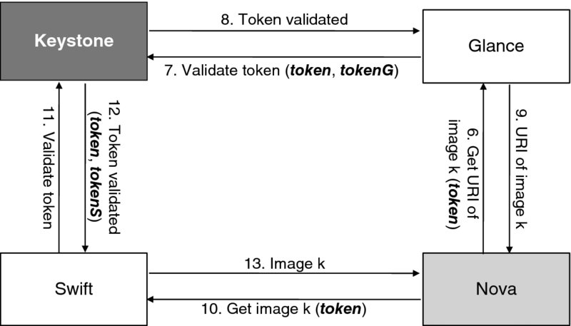
Figure 7.27 Additional steps for VM provisioning.
A token typically captures the issuance time, expiration time, and user information. It may also define the scope—the information about roles concerning a domain. A token is called “unscoped” if it does not contain such information. Such a token is useless for resource access, but it can be used as a stepping stone to discover accessible projects and then have it exchanged for a scoped token. A token may even capture a catalog of services to which the user is entitled.
By now, it should be clear that Keystone tokens are bearer tokens. As the basis for service access, they must be protected from disclosure, forgery, and alteration. Disclosure protection is a huge subject itself, hinging on comprehensive communication and information security. Forgery prevention and integrity protection are a different matter, affected by the structure and format of tokens. While custom tokens can be used through external modules, Keystone natively supports three types of tokens as of the Juno release respectively named Universally Unique IDentifier (UUID), Public Key Infrastructure (PKI), and compressed PKI.
A UUID token is a randomly generated string that serves as a reference to a piece of information stored in a persistent token database. By itself, it is meaningless. A service has to invoke Keystone to verify any received UUID tokens. (This is, in fact, what we saw in the workflows earlier.) A UUID token is valid if there is a not-yet-expired matching token in the database. The constraint that only Keystone can verify tokens makes it a potential bottleneck. There is, however, an upside. The size of a UUID token is small and fixed (i.e., 128 bits) so that it will never cause an API call to fail in practice.107 In addition, it is relatively hard to forge a valid UUID token. Keystone uses UUID version 4 as specified in IETF RFC 4122.108 Such a UUID has 122 bits pseudo-randomly generated. This means that the probability for creating a UUID that is already in the database is 2−122. Finally, altering an existing token gives rise to a brand new one. Again, the probability for the new token to be in the database is 2−122.
Unlike a UUID token, a PKI token is not merely a pointer to a data structure, but a data structure itself. This structure stores the user identity and entitlement information. To prevent modification of the contents, the data structure contains a digital signature. An immediate benefit of such a token is that it is verifiable by a service endpoint. So the concern about bottlenecks and weak scalability in the case of UUID tokens is gone. Specifically, a PKI token is a Cryptographic Message Syntax (CMS)109 string (encoded in base-64110 notation). This token contains a digitally-signed block of data. The specifics of the data are context-dependent. As a result, the token size varies. Figure 7.28 shows, as an example, a token in JSON before signing. Note that it includes the obligatory information on the list of methods used for user authentication. In addition, to allow an authenticated user with a token to get another token of a different scope, token is recognized as an authentication method as well. When an authenticated user does so, the list of authentication methods will include both “password” and “token.”
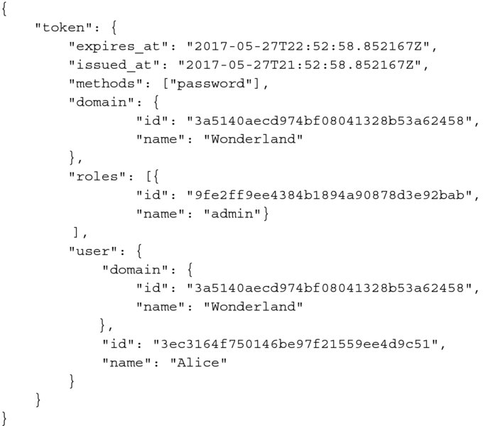
Figure 7.28 An example token (unsigned).
By default, RSA-SHA256 is the algorithm used to produce a signature in Keystone. This means that the digest of the data block to be signed is computed using the SHA256 algorithm111 and the signature is computed by encrypting the digest using an RSA private key. A PKI token is valid if the signature is valid, among other things.112 To facilitate signature validation by another service endpoint, Keystone supports retrieval of the signing and other relevant certificates through its API.
One characteristic of a PKI token is its large size. A token could easily be several thousand bytes in size. Especially if the token includes a catalog of the services accessible to the user, its size could reach the practical limit of an HTTP header and break the operation. To reduce the token size, Keystone supports compression though.
Unfortunately, there is no guarantee that the size of a compressed PKI token always stays within the limits of an HTTP header. Because of the tradeoffs between UUID and PKI tokens, the default token type in Keystone is not a settled matter. It was UUID from the beginning, became PKI in the Grizzly release, and swung back to UUID since the Juno release.113
So far, we have seen how Keystone tokens enable single sign-on and basic delegation. As useful as they are, these tokens are short-lived (by design). They might expire (and in real life actually tend to expire!) when the deadline for an action at hand is unknown. (Imagine the task of launching a new server when the CPU utilization of the existing server reaches 60%. Depending on the clients' activity, this may happen in a few minutes, a few years, or never!)
Thus we need some other mechanism to obtain tokens dynamically. For this purpose, Keystone introduces the construct of trust to capture who delegates authority, who is the delegate, the scope and duration of the delegation, and other pertinent information.
Trust is not unlike a power-of-attorney document. The delegating entity creates it and hands it to the delegate. Now the delegate presents the trust to get a token. The idea underlying this arrangement is that a token is short-lived but the trust is long-lived.
In Keystone parlance, the delegating entity is called the trustor and the delegate, the trustee. Only the trustor can create a trust. Based on the trust, the trustee (but no one else) can obtain a fresh token in order to carry out a delegated task. The token will have the same scope as the trust. Such a token is known as a trust token. Its structure is the same as that of a normal token, if not for an additional data block to carry trust-related information. Naturally, the trust may not be expired when used for getting a token.
To explore how trusts work, let us go through the related part of the workflow for spinning up a new stack (e.g., a virtual machine as a degenerate case) automatically. Figure 7.29 shows a greatly simplified workflow for instantiating a template to provision a stack and for scaling-out automatically when the running stack is overloaded. Steps 1 to 5 are essentially the same as before when Heat is not involved. After step 5, some heavy lifting will take place to launch the first stack. Here we will focus on the extra steps required to set up the stage for automation. These steps are shown in Figure 7.30. First we set an alarm (steps 5a to 5d), then we create a trust to allow Heat (as the service user) to have Alice's delegation (steps 5e and 5f). After these steps, Heat is in the monitoring mode, waiting for the alarm to go off at Ceilometer. Finally, an alarm notification arrives as shown in step 7.114 Upon receiving the notification, Heat proceeds to get a trust token as shown in step 8. Here Heat needs to present its own token to prove that it is the trustee identified in the trust. Upon successful authentication, Heat receives a trust token, which allows it to launch a new virtual machine on behalf of Alice.
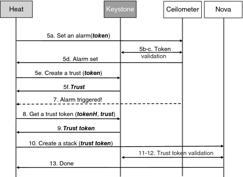
Figure 7.30 Additional steps for auto-scaling.
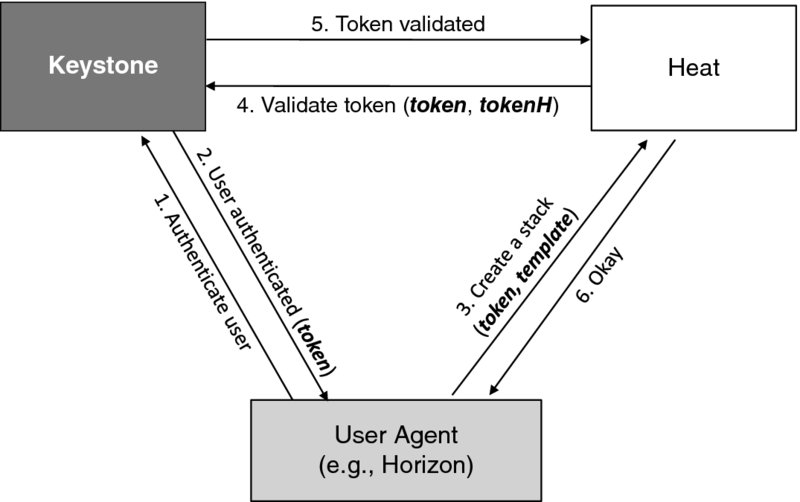
Figure 7.29 A simplified workflow for auto-scaling.
Figure 7.31 shows an example of a trust. The structure is pretty much self-explanatory except for the “impersonation” field. If it is set to false, the user field of the trust token based on the trust will represent the trustee. Otherwise, the user field will represent the trustor. In other words, the trustee impersonates the trustor when presenting the trust token for validation. This is the case in our example where the trust token has Alice as the user. Impersonation is enabled by default in Keystone, given the goal of providing automated life cycle management of a user's stacks. Two other fields also have default values set toward the same goal: “expires_at” and “remaining_uses”. The “expires_at” field, if unspecified, will have the effect that the trust is valid until explicitly revoked. Similarly, the “remaining_uses” field, if unspecified, will have the effect that the trust can be used to get a token an unlimited number of times. Finally, trusts are immutable once created. To update a trust relationship, the trustor deletes the old trust and creates a new one. Upon deletion of the old token, any tokens derived from it are revoked. If the trustor loses any delegated privileges, the trust becomes invalid.
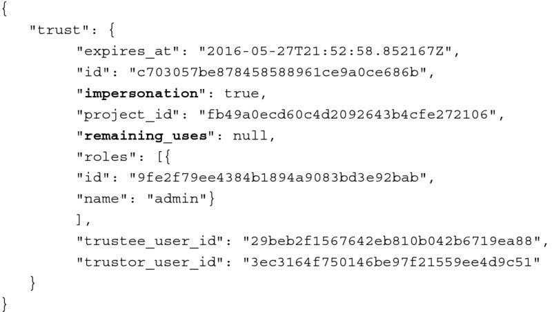
Figure 7.31 An example trust.
Support for identity federation results in a new authentication workflow. When receiving an authentication request, Keystone, instead of handling the request itself, redirects it to the external identity provider. Upon receiving the redirected request, the identity provider performs the steps to authenticate the user, and then redirects the result as an attestation to Keystone. If the user is attested authentic, Keystone generates an unscoped token, based on which the user can find out the accessible projects and obtain another token with a proper scope. Tokens generated for a federated user are distinct—they carry information related to federation, such as the name of the identity provider, the identity federation protocol, and the associated groups.
Overall, the token service supports generation, revocation, and validation not only of tokens but also of trusts. As a centralized service, it has been influenced by OAuth 2.0 and can be mapped directly to the latter's authorization server. Also similar are the money-like quality of tokens—that any bearer of a token may use it—and the use of JSON for token description. Nevertheless, the Keystone token service has its own protocol (in the form of a REST API) because very different use cases are targeted. The use cases involve essentially two actors (i.e., the user and Cloud infrastructure service provider), and they are high in automation but low in interactivity. As a result, a different user consent model for delegation suffices—a user's consent to delegate is implied as soon as the user is authenticated to get a service.
Notes
References
- Blatter, A. (1997). Instrumentation and Orchestration, 2nd edn. Shirmer, Boston, MA.
- Hogan, M., Liu, F., Sokol, A., and Tong, J. (2011) NIST Cloud Computing Standards Roadmap—Version 1.0. Special Publication 500-291. National Institute of Standards and Technology, US Department of Commerce, Gaithersburg, Maryland.
- Liu, F., Tong, J., Mao, J., et al. (2011) NIST Cloud Computing Reference Architecture. Special Publication 500-292. National Institute of Standards and Technology, US Department of Commerce, Gaithersburg, Maryland.
- Stroustrup, B. (2013) The C++ Programming Language, 4th edn. Addison-Wesley, New York.
- Birman, K.P. (2012) Guide to Reliable Distributed Systems: Building High-Assurance Applications and Cloud-Hosted Services. Springer-Verlag, London.
- Lapierre, M. (1999) The TINA Book: A Co-operative Solution for a Competitive World. Prentice-Hall, Englewood Cliffs, NJ.
- Thompson, M., Belshe, M., and Peon, R. (2014) Hypertext Transfer Protocol version 2. Work in progress. https://tools.ietf.org/html/draft-ietf-httpbis-http2-12 IETF.
- Erl, T. (2005) Service-Oriented Architecture: Concepts, Technology, and Design. Prentice-Hall, Englewood Cliffs, NJ.
- Culler, D.E. (1986) Data Flow Architectures. MIT Technical Memorandum MIT/LCS/TM-294, February 12. http://csg.csail.mit.edu/pubs/memos/Memo-261-1/Memo-261-2.pdf.
- Slutsman, L., Lu, H., Kaplan, M.P., and Faynberg, I. (1994) Achieving platform-independence of service creation through the application-oriented parsing language. Proceedings of the IEEE IN'94 Workshop, Heidelberg, Germany, pp. 549–561.
- Amin, K., Hategan, M., von Laszewski, G., et al. (2004) GridAnt: A client-controllable grid workflow system. 37th Hawaii International Conference on System Science, pp. 210–220. (Also available in an Argonne National Laboratory preprint: ANL/MCS-P1098-1003 at www.mcs.anl.gov/papers/P109Apdf.)
- Kalenkova, A. (2012) An algorithm of automatic workflow optimization. Programming and Computer Software, 38(1), 43–56. Springer, New York.
- Rey, R.F. and Members of the Technical Staff of AT&T Bell Laboratories (1983) Engineering and Operations in the Bell System, 2nd edn. AT&T Bell Laboratories, Murray Hill, NJ.
- Ebner, G.C., Lybarger, T.K., and Coville, P. (1991) AT&T and TÉLÉSYSTÉMES partnering in France. AT&T Technical Journal, 71(5), 45–56.
- International Telecommunication Union (1998) International Standard 9596-1, ITU-T Recommendation X.711: Information Technology—Open Systems Interconnection—Common Management Information Protocol: Specification.
- Dick, K. and Shin, B. (2001) Implementation of the Telecom Management Network (TMN) at WorldCom—Strategic Information Systems Methodology Focus. Journal of Systems Integration, 10(4), 329–354.
- Schneiderman, A. and Casati, A. (2008) Fixed Mobile Convergence. McGraw-Hill, New York.
- Anderson, T.W., Busschbach, P., Faynberg, I., et al. (2007) The emerging resource and admission control function standards and their application to the new triple-play services. Bell Labs Technical Journal, 12, 5–21.
- International Telecommunication Union (2011) ITU-T Recommendation Labs.: Resource and Admission Control Functions in Next Generation Networks, Geneva.
- Camarillo, G. and Garcia-Martin, M.A. (2008) The 3G IP Multimedia Subsystem: Merging the Internet and the Cellular Worlds, 3rd edn. John Wiley & Sons, Inc., Hoboken.
- European Telecommunications Standards Institute (2005) Resource and Admission Control Sub-system (RACS), Functional Architecture. ETSI ES 282 003, v.1.6.8, December. www.etsi.org/services_products/freestandard/home.htm.
- Wayner, P. (2013) Puppet or Chef: The configuration management dilemma. Network World. www.infoworld.com/article/2614204/data-center/puppet-or-chef–the-configuration-management-dilemma.html.
- Rivest, R.L., Shamir, A., and Adleman, L. (1978) A method for obtaining digital signatures and public-key cryptosystems. Communications of the ACM, 21(2), 120–126.
- Diffie, W. and Hellman, M.E. (1976) New directions in cryptography. IEEE Transactions on Information Theory, 22(6), 644–654.
- Kohnfelder, L.M. (1978) Towards a practical public-key cryptosystem. B.S. thesis, Massachusetts Institute of Technology.
- International Telecommunication Union (2012) Information Technology—Open Systems Interconnection—The Directory: Public-Key and Attribute Certificate Frameworks. ITU-T Recommendation X.509, December. www.itu.int.
- Bishop, M. (2014) Mathematical models of computer security. In Bosworth, S., Kabay, M.E., and Whyne, E. (eds), Computer Security Handbook, 6th edn. John Wiley & Sons Inc., Hoboken, Chapter 9.
- Brand, S.L. (1985) DoD 5200.28-STD Department of Defense Trusted Computer System Evaluation Criteria (Orange Book), National Computer Security Center, pp. 1–94.
- La Padula, L.J. and Bell, D.E. (1973) Secure Computer Systems: Mathematical Foundations. MTR-2547-VOL-1, Mitre Corporation, Bedford, MA.
- Biba, K.J. (1977) Integrity Considerations for Secure Computer Systems. MTR-3153-REV-1, Mitre Corporation, Bedford, MA.
- Boebert, W.E. and Kain, R.Y. (1985) A practical alternative to hierarchical integrity policies. Proceedings of the 8th National Computer Security Conference, Gaithersburg, MD.
- Boebert, W.E. and Kain, R.Y. (1996) A further note on the confinement problem. IEEE Security Technology '96, 30th Annual 1996 International Carnahan Conference, Lexington, Kentucky.
- Badger, L., Sterne, D.F., Sherman, D.L., et al. (1995) Practical domain and type enforcement for UNIX. Proceedings of IEEE Symposium on Security and Privacy, Okland, CA.
- Ferraiolo, D.D., Kuhn, R., and Chandramouli, R. (2003) Role-based Access Control. Artech House, Boston, MA.
- David, F. and Kuhn, R. (1992) Role-based access controls. Proceedings of 15th NIST/NCSC National Computer Security Conference, Baltimore, MD.
- American National Standards Institute (2004) Role Based Access Control. ANSI INCITS 359-2004, February, New York, NY.
- Bonneau Osborn, S., Sandhu, R., and Munawer, Q. (2000) Configuring role-based access control to enforce mandatory and discretionary access control policies. ACM Transactions on Information and System Security (TISSEC), 3(2), 85–106.