
CHAPTER 3
CPU Virtualization
This chapter explains the concept of a virtual machine as well as the technology that embodies it. The technology is rather complex, inasmuch as it encompasses the developments in computer architecture, operating systems, and even data communications. The issues at stake here are most critical to Cloud Computing, and so we will take our time.
To this end, the name of the chapter is something of a misnomer: it is not only the CPU that is being virtualized, but the whole of the computer, including its memory and devices. In view of that it might have been more accurate to omit the word “CPU” altogether, had it not been for the fact that in the very concept of virtualization the part that deals with the CPU is the most significant and most complex.
We start with the original motivation and a bit of history—dating back to the early 1970s—and proceed with the basics of the computer architecture, understanding what exactly program control means and how it is achieved. We spend a significant amount of time on this topic also because it is at the heart of security: it is through manipulation of program control that major security attacks are effected.
After addressing the architecture and program control, we will selectively summarize the most relevant concepts and developments in operating systems. Fortunately, excellent textbooks exist on the subject, and we delve into it mainly to highlight the key issues and problems in virtualization. (The very entity that enables virtualization, a hypervisor, is effectively an operating system that “runs” conventional operating systems.) We will explain the critical concept of a process and list the operating system services. We also address the concept of virtual memory and show how it is implemented—a development which is interesting on its own, while setting the stage for the introduction of broader virtualization tasks.
Once the stage is set, this chapter will culminate with an elucidation of the concept of the virtual machine. We will concentrate on hypervisors, their services, their inner workings, and their security, all illustrated by live examples.
3.1 Motivation and History
Back in the 1960s, as computers were evolving to become ever faster and larger, the institutions and businesses that used them weighed up the pros and cons when deciding whether to replace older systems. The major problem was the same as it is now: the cost of software changes, especially because back then these costs were much higher and less predictable than they are now. If a business already had three or four computers say, with all the programs installed on each of them and the maintenance procedures set in place, migrating software to a new computer—even though a faster one than all the legacy machines combined—was a non-trivial economic problem. This is illustrated in Figure 3.1.
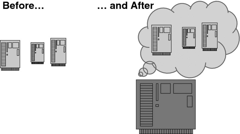
Figure 3.1 A computing environment before and after virtualization.
But the businesses were growing, and so were their computing needs. The industry was working to address this problem, with the research led by IBM and MIT. To begin with, time sharing (i.e., running multiple application processes in parallel) and virtual memory (i.e., providing each process with an independent full-address-range contiguous memory array) had already been implemented in the IBM System 360 Model 67 in the 1960s, but these were insufficient for porting multiple “whole machines” into one machine. In other words, a solution in which an operating system of a stand-alone machine could be run as a separate user process now executing on a new machine was not straightforward. The reasons are examined in detail later in this chapter; in a nutshell, the major obstacle was (and still is) that the code of an operating system uses a privileged subset of instructions that are unavailable to user programs.
The only way to overcome this obstacle was to develop what was in essence a hyper operating system that supervised other operating systems. Thus, the term hypervisor was coined. The joint IBM and MIT research at the Cambridge Scientific Center culminated in the Control Program/Cambridge Monitor System (CP/CMS). The system, which has gone through four major releases, became the foundation of the IBM VM/370 operating system, which implemented a hypervisor. Another seminal legacy of CP/CMS was the creation of a user community that pre-dated the open-source movement of today. CP/CMS code was available at no cost to IBM users.
IBM VM/370 was announced in 1972. Its description and history are well presented in Robert Creasy's famous paper [1]. CMS, later renamed the Conversational Monitor System, was part of it. This was a huge success, not only because it met the original objective of porting multiple systems into one machine, but also because it effectively started the virtualization industry—a decisive enabler of Cloud Computing.
Since then, all hardware that has been developed for minicomputers and later for microcomputers has addressed virtualization needs in part or in full. Similarly, the development of the software has addressed the same needs—hand in hand with hardware development.
In what follows, we will examine the technical aspects of virtualization; meanwhile, we can summarize its major achievements:
- Saving the costs (in terms of space, personnel, and energy—note the green aspect!) of running several physical machines in place of one;
- Putting to use (otherwise wasted) computing power;
- Cloning servers (for instance, for debugging purposes) almost instantly;
- Isolating a software package for a specific purpose (typically, for security reasons)—without buying new hardware; and
- Migrating a machine (for instance, when the load increases) at low cost and in no time—over a network or even on a memory stick.
The latter capability—to move a virtual machine from one physical machine to another—is called live migration. In a way, its purpose is diametrically opposite to the one that brought virtualization to life—that is, consolidating multiple machines on one physical host. Live migration is needed to support elasticity, as moving a machine to a new host—with more memory and reduced load—can increase its performance characteristics.
3.2 A Computer Architecture Primer
This section is present only to make the book self-contained. It provides the facts that we find essential to understanding the foremost virtualization issues, especially as far as security is concerned. It can easily be skipped by a reader familiar with computer architecture and—more importantly—its support of major programming control constructs (procedure calls, interrupt and exception handling). To a reader who wishes to learn more, we recommend the textbook [2]—a workhorse of Computer Science education.
3.2.1 CPU, Memory, and I/O
Figure 3.2 depicts pretty much all that is necessary to understand the blocks that computers are built of. We will develop more nuanced understanding incrementally.
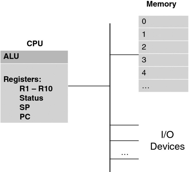
Figure 3.2 Simplified computer architecture.
The three major parts of a computer are:
- The Central Processing Unit (CPU), which actually executes the programs;
- The computer memory (technically called Random Access Memory (RAM)), where both programs and data reside; and
- Input/Output (I/O) devices, such as the monitor, keyboard, network card, or disk.
All three are interconnected by a fast network, called a bus, which also makes a computer expandable to include more devices.
The word random in RAM (as opposed to sequential) means that the memory is accessed as an array—through an index to a memory location. This index is called a memory address.
Note that the disk is, in fact, also a type of memory, just a much slower one than RAM. On the other hand, unlike RAM, the memory on the disk and other permanent storage devices is persistent: the stored data are there even after the power is turned off.
At the other end of the memory spectrum, there is much faster (than RAM) memory inside the CPU. All pieces of this memory are distinct, and they are called registers. Only the registers can perform operations (such as addition or multiplication—arithmetic operations, or a range of bitwise logic operations). This is achieved through a circuitry connecting the registers with the Arithmetic and Logic Unit (ALU). A typical mode of operation, say in order to perform an arithmetic operation on two numbers stored in memory, is to first transfer the numbers to registers, and then to perform the operation inside the CPU.
Some registers (we denote them R1, R2, etc.) are general purpose; others serve very specific needs. For the purposes of this discussion, we identify three registers of the latter type, which are present in any CPU:
- The Program Counter (PC) register always points to the location memory where the next program instruction is stored.
- The Stack Pointer (SP) register always points to the location of the stack of a process—we will address this concept in a moment.
- The STATUS register keeps the execution control state. It stores, among many other things, the information about the result of a previous operation. (For instance, a flag called the zero bit of the STATUS register is set when an arithmetical operation has produced zero as a result. Similarly, there are positive-bit and negative-bit flags. All these are used for branching instructions: JZ—jump if zero; JP—jump if positive; JN—jump if negative. In turn, these instructions are used in high-level languages to implement conditional if statements.) Another—quite essential to virtualization—use of the STATUS register, which we will discuss later, is to indicate to the CPU that it must work in trace mode, that is execute instructions one at a time. We will introduce new flags as we need them.
Overall, the set of all register values (sometimes called the context) constitutes the state of a program being executed as far as the CPU is concerned. A program in execution is called a process.1 It is a very vague definition indeed, and here a metaphor is useful in clarifying it. A program can be seen as a cookbook, a CPU as a cook—using kitchen utensils, and then a process can be defined as the act of cooking a specific dish described in the cookbook.
A cook can work on several dishes concurrently, as long as the state of a dish (i.e., a specific step within the cookbook) is remembered when the cook switches to preparing another dish. For instance, a cook can put a roast into the oven, set a timer alarm, and then start working on a dessert. When the alarm rings, the cook will temporarily abandon the dessert and attend to the roast.
With that, the cook must know whether to baste the roast or take it out of the oven altogether. Once the roast has been attended to, the cook can resume working on the dessert. But then the cook needs to remember where the dessert was left off!
The practice of multi-programming—as maintained by modern operating systems—is to store the state of the CPU on the process stack, and this brings us to the subject of CPU inner workings.
We will delve into this subject in time, but to complete this section (and augment a rather simplistic view of Figure 3.2) we make a fundamental observation that modern CPUs may have more than one set of identical registers. As a minimum, one register set is reserved for the user mode—in which application programs execute– and the other for the system (or supervisory, or kernel) mode, in which only the operating system software executes. The reason for this will become clear later.
3.2.2 How the CPU Works
All things considered, the CPU is fairly simple in its concept. The most important point to stress here is that the CPU itself has no “understanding” of any program. It can deal only with single instructions written in its own, CPU-specific, machine code. With that, it keeps the processing state pretty much for this instruction alone. Once the instruction has been executed, the CPU “forgets” everything it had done and starts a new life executing the next instruction.
While it is not at all necessary to know all the machine code instructions of any given CPU in order to understand how it works, it is essential to grasp the basic concept.
As Donald Knuth opined in his seminal work [3], “A person who is more than casually interested in computers should be well schooled in machine language, since it is a fundamental part of a computer.” This is all the more true right now—without understanding the machine language constructs one cannot even approach the subject of virtualization.
Fortunately, the issues involved are surprisingly straightforward, and these can be explained using only a few instructions. To make things simple, at this point we will avoid referring to the instructions of any existing CPU. We will make up our own instructions as we go along. Finally, even though the CPU “sees” instructions as bit strings, which ultimately constitute the machine-level code, there is no need for us even to think at this level. We will look at the text that encodes the instructions—the assembly language.
Every instruction consists of its operation code opcode, which specifies (no surprise here!) an operation to be performed, followed by the list of operands. To begin with, to perform any operation on a variable stored in memory, a CPU must first load this variable into a register.
As a simple example: to add two numbers stored at addresses 10002 and 10010, respectively, a program must first transfer these into two CPU registers—say R1 and R2. This is achieved with a LOAD instruction, which does just that: loads something into a register. The resulting program looks like this:
LOAD R1 @10002
LOAD R2 @10010
ADD R1, R2
(The character “@” here, in line with assembly-language conventions, signals indirect addressing. In other words, the numeric string that follows “@” indicates an address from which to load the value of a variable rather than the value itself. When we want to signal that the addressing is immediate—that is, the actual value of a numeric string is to be loaded—we precede it with the character “#,” as in LOAD R1, #3.)
The last instruction in the above little program, ADD, results in adding the values of both registers and storing them—as defined by our machine language—in the second operand register, R2.
In most cases, a program needs to store the result somewhere. A STORE instruction—which is, in effect, the inverse of LOAD—does just that. Assuming that variables x, y, and z are located at addresses 10002, 10010, and 10020, respectively, we can augment our program with the instruction STORE R2, @10020 to execute a C-language assignment statement: z = x + y.
Similarly, arithmetic instructions other than ADD can be introduced, but they hardly need any additional explanation. It is worth briefly mentioning the logical instructions: AND and OR, which perform the respective operations bitwise. Thus, the instruction OR R1, X sets those bits of R1 that are set in X; and the instruction AND R1, X resets those bits of R1 that are reset in X. A combination of logical instructions, along with the SHIFT instruction (which shifts the register bits a specified number of bits to the right or to the left, depending on the parameter value, while resetting the bits that were shifted), can achieve any manipulation of bit patterns.
We will introduce other instructions as we progress. Now we are ready to look at the first—and also very much simplified—description of a CPU working mechanism, as illustrated in Figure 3.3. We will keep introducing nuances and important detail to this description.
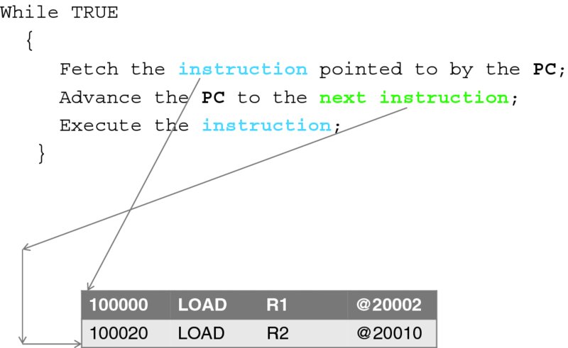
Figure 3.3 A simplified CPU loop (first approximation).
The CPU works like a clock—which is, incidentally, a very deep analogy with the mechanical world. All the operations of a computer are carried out at the frequency of the impulses emitted by a device called a computer clock, just as the parts of a mechanical clock move in accordance with the swinging of a pendulum. To this end, the speed of a CPU is measured by the clock frequency it can support.
All a CPU does is execute a tight infinite loop, in which an instruction is fetched from the memory and executed. Once this is done, everything is repeated. The CPU carries no memory of the previous instruction, except what is remaining in its registers.
If we place our little program into memory location 200000,2 then we must load the PC register with this value so that the CPU starts to execute the first instruction of the program. The CPU then advances the PC to the next instruction, which happens to be at the address 200020. It is easy to see how the rest of our program gets executed.
Here, however, for each instruction of our program, the next instruction turns out to be just the next instruction in the memory. This is definitely not the case for general programming, which requires more complex control-transfer capabilities, which we are ready to discuss now.
3.2.3 In-program Control Transfer: Jumps and Procedure Calls
At a minimum, in order to execute the “if–then–else” logic, we need an instruction that forces the CPU to “jump” to an instruction stored at a memory address different from that of the next instruction in contiguous memory. One such instruction is the JUMP instruction. Its only operand is a memory address, which becomes the value of the PC register as a result of its execution.
Another instruction in this family, JNZ (Jump if Non-Zero) effects conditional transfer to an address provided in the instruction's only operand. Non-zero here refers to the value of a zero bit of the STATUS register. It is set every time the result of an arithmetic or logical operation is zero—a bit of housekeeping done by the CPU with the help of the ALU circuitry. When executing this instruction, a CPU does nothing but change the value of the PC to that of the operand. The STATUS register typically holds other conditional bits to indicate whether the numeric result is positive or negative. To make the programmer's job easier (and its results faster), many CPUs provide additional variants of conditional transfer instructions.
More interesting—and fundamental to all modern CPUs—is an instruction that transfers control to a procedure. Let us call this instruction JPR (Jump to a Procedure). Here, the CPU helps the programmer in a major way by automatically storing the present value of the PC (which, according to Figure 3.3, initially points to the next instruction in memory) on the stack3—pointed to by the SP. With that, the value of the SP is changed appropriately. This allows the CPU to return control to exactly the place in the program where the procedure was called. To achieve that, there is an operand-less instruction, RTP (Return from a Procedure). This results in popping the stack and restoring the value of the PC. This must be the last instruction in the body of every procedure.
There are several important points to consider here.
First, we observe that a somewhat similar result could be achieved just with the JUMP instruction alone; after all, a programmer (or a compiler) could add a couple of instructions to store the PC on the stack. A JUMP—to the popped PC value—at the end of the procedure would complete the task. To this end, everything would have worked even if the CPU had had no notion of the stack at all—it could have been a user-defined structure. The two major reasons that modern CPUs have been developed in the way we describe here are (1) to make procedure calls execute faster (by avoiding the fetching of additional instructions) and (2) to enforce good coding practices and otherwise make adaptability of the ALGOL language and its derivatives straightforward (a language-directed design). As we have noted already, the recursion is built in with this technique.
Second, the notion of a process as the execution of a program should become clearer now. Indeed, the stack traces the control transfer outside the present main line of code. We will see more of this soon. It is interesting that in the 1980s, the programmers in Borroughs Corporation, whose highly innovative—at that time—CPU architecture was ALGOL-directed, used the words process and stack interchangeably! This is a very good way to think of a process—as something effectively represented by its stack, which always traces a single thread of execution.
Third, this structure starts to unveil the mechanism for supporting multi-processing. Assuming that the CPU can store all its states on a process stack and later restore them—the capability we address in the next section—we can imagine that a CPU can execute different processes concurrently by switching among respective stacks.
Fourth—and this is a major security concern—the fact that, when returning from a procedure, the CPU pops the stack and treats as the PC value whatever has been stored there means that if one manages to replace the original stored value of the PC with another memory address, the CPU will automatically start executing the code at that memory address. This fact has been exploited in distributing computer worms. A typical technique that allows overwriting the PC is when a buffer is a parameter to a procedure (and thus ends up on the stack). For example, if the buffer is to be filled by reading a user-supplied string, and the procedure's code does not check the limits of the buffer, this string can be carefully constructed to pass both (1) the worm code and (2) the pointer to that code so that the pointer overwrites the stored value of the PC. This technique has been successfully tried with the original Morris's worm of 1988 (see [4] for a thorough technical explanation in the context of the worm's history unfolding).4 We will address security in the last section of this chapter.
For what follows, it is important to elaborate more on how the stack is used in implementing procedure calls.
With a little help from the CPU, it is now a programmer's job (if the programmer writes in an assembly language) or a compiler's job (if the programmer writes in a high-level language) to handle the parameters for a procedure. The long-standing practice has been to put them on the stack before calling the procedure.
Another essential matter that a programmer (or a compiler writer) must address in connection with a procedure call is the management of the variables that are local to the procedure. Again, a long-standing practice here is to allocate all the local memory on the stack. One great advantage of doing so is to enable recursion: each time a procedure is invoked, its parameters and local memory are separate from those of the previous invocation.
Figure 3.4 illustrates this by following the execution of an example program,5 along with the state of the process stack at each instruction. Here, a procedure stored at location 1000000 is called from the main program. The procedure has two parameters stored at locations 20002 and 20010, respectively.
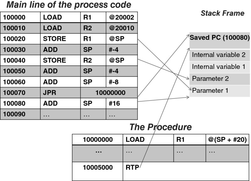
Figure 3.4 The process stack and the procedure call.
The first six instructions implement the act of pushing the procedure parameters on the stack. (Note that we consider each parameter to be four units long, hence ADD SP #-4; of course, as the stack—by convention—diminishes, the value of the stack pointer is decreased.)
The seventh instruction (located at the address 100060), prepares the internal memory of the procedure on the stack, which happens in this particular case to need eight units of memory for the two, four-unit-long variables.
In the eighth instruction, the procedure code is finally invoked. This time the CPU itself pushes the value of the PC (also four bytes long) on the stack; then, the CPU loads the PC with the address of the procedure. At this point, the procedure's stack frame has been established.
Execution of the first instruction of the procedure results in retrieving the value of the first parameter, which, as we know, is located on the stack, exactly 20 units above the stack pointer. Similarly, another parameter and the internal variables are accessed indirectly, relative to the value of the stack pointer. (We intentionally did not show the actual memory location of the stack: with this mode of addressing, that location is irrelevant as long as the stack is initialized properly! This is a powerful feature in that it eliminates the need for absolute addressing. Again, this feature immediately supports recursion, as the same code will happily execute with a new set of parameters and new internal memory.)
When the procedure completes, the RTP instruction is executed, which causes the CPU to pop the stack and restore the program counter to its stored value. Thus, the program control returns to the main program. The last instruction in the example restores the stack to its original state.
A minor point to note here is that a procedure may be a function—that is, it may return a value. How can this value be passed to the caller? Storing it on the stack is one way of achieving that; the convention of the C-language compilers though has been to pass it in a register—it is faster this way.
This concludes the discussion of a procedure call. We are ready to move on to the next level of detail of CPU mechanics, motivated by the new forms of control transfer.
3.2.4 Interrupts and Exceptions—the CPU Loop Refined
So far, the simple CPU we have designed can only deal with one process. (We will continue with this limitation in the present section.) The behavior of the process is determined by the set of instructions in its main line code—and the procedures, to which control is transferred—but still in an absolutely predictable (sometimes called “deterministic” or “synchronous”) manner. This type of CPU existed in the first several decades of computing, and it does more or less what is needed to perform in-memory processing. It has been particularly suitable for performing complex mathematical algorithms, so long as not much access to I/O devices is needed.
But what happens when an I/O request needs to be processed? With the present design, the only solution is to have a subroutine that knows how to access a given I/O device—say a disk or a printer. We can assume that such a device is memory-mapped: there is a location in main memory to write the command (read or write), pass a pointer to a data buffer where the data reside (or are to be read into), and also a location where the status of the operation can be checked. After initiating the command, the process code can do nothing else except execute a tight loop checking for the status.
Historically, it turned out that for CPU-intensive numeric computation such an arrangement was more or less satisfactory, because processing I/O was an infrequent action—compared with computation. For business computing, however—where heavy use of disks, multiple tapes, and printers was required most of the time—CPU cycles wasted on polling are a major performance bottleneck. As the devices grew more complex, this problem was further aggravated by the need to maintain interactive device-specific protocols, which required even more frequent polling and waiting. (Consider the case when each byte to a printer needs to be written separately, followed by a specific action based on how the printer responds to processing the previous byte.) For this reason, the function of polling was transferred into the CPU loop at the expense of a change—and a dramatic change at that!—of the computational model.
The gist of the change is that whereas before a subroutine was called from a particular place in a program determined by the programmer (whether from the main line or another subroutine), now the CPU gets to call certain routines by itself, acting on a communication from a device. With that, the CPU effectively interrupts the chain of instructions in the program, which means that the CPU needs to return to this chain exactly at the same place where it was interrupted. More terminology here: the signal from a device, which arrives asynchronously with respect to the execution of a program, is appropriately called an interrupt; everything that happens from that moment on, up to the point when the execution of the original thread of instruction resumes, is called interrupt processing.
Of course, the actual code for processing the input from a device—the interrupt handling routine—still has to be written by a programmer. But since this routine is never explicitly called from a program, it has to be placed in a specified memory location where the CPU can find it. This location is called an interrupt vector. Typically, each device has its own vector—or even a set of vectors for different events associated with the device. (In reality this may be more complex, but such a level of detail is unnecessary here.) At initialization time, a program must place the address of the appropriate interrupt routine in the slot assigned to the interrupt vector. The CPU jumps to the routine when it detects a signal from the device. When the interrupt is serviced, the control is returned to the point where the execution was interrupted—the execution of the original program is resumed.
This mechanism provides the means to deal with the external events that are asynchronous with the execution of a program. For reasons that will become clear later, the same mechanism is also used for handling certain events that are actually synchronous with program execution. They are synchronous in that they are caused by the very instruction to be executed (which, as a result, may end up being not executed). Important examples of such events are:
- A computational exception (an attempt to divide by zero).
- A memory-referencing exception (such as an attempt to read or write to a non-existent location in memory).
- An attempt to execute a non-existing instruction (or an instruction that is illegal in the current context).
- (A seemingly odd one!) An explicit in-line request (called a trap) for processing an exception. In our CPU this is caused by an instruction (of the form TRAP <trap number>) which allows a parameter—the trap number—to associate a specific interrupt vector with the trap, so that different trap numbers may be processed differently.
The fundamental need for the trap instruction will be explained later, but one useful application is in setting breakpoints for debugging. When a developer wants a program to stop at a particular place so that the memory can be examined, the resulting instruction is replaced with the trap instruction, as Figure 3.5 illustrates. The same technique is used by hypervisors to deal with non-virtualizable instructions, and we will elaborate on this later too.
Figure 3.6 illustrates the following discussion.
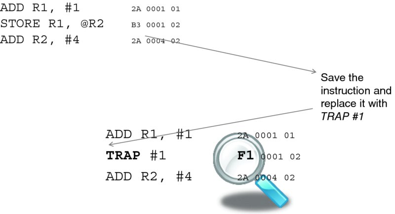
Figure 3.5 Setting a breakpoint.
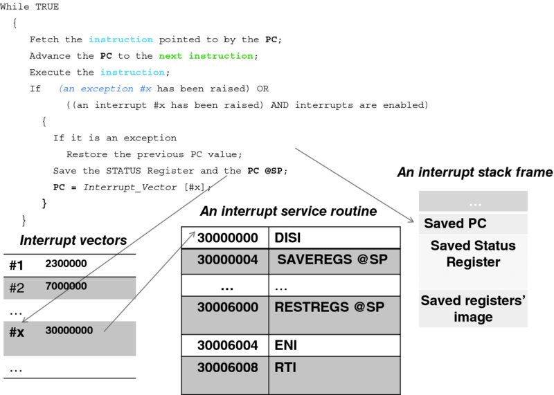
Figure 3.6 The second approximation of the CPU loop.
We are ready to modify the simplistic CPU loop of Figure 3.3. The new loop has a check for an interrupt or exception signal. Note that, as far as the CPU is concerned, the processing is quite deterministic: the checking occurred exactly at the end of the execution of the present instruction, no matter when the signal arrived. The CPU's internal circuitry allows it to determine the type of interrupt or exception, which is reflected in the interrupt number x. This number serves as the index to the interrupt vector table.6 There is an important difference between processing interrupts and processing exceptions: an instruction that has caused an exception has not been executed; therefore, the value of the PC to be stored must remain the same. Other than that, there is no difference in processing between interrupts and exceptions, and to avoid pedantic repetition, the rest of this section uses the word “interrupt” to mean “an interrupt or an exception.”
The table on the left in Figure 3.6 indicates that the interrupt service routine for processing interrupt x starts at location 30000000. The CPU deals with this code similarly to that of a procedure; however, this extraordinary situation requires an extraordinary set of actions! Different CPUs do different things here; our CPU does more or less what all modern CPUs do.
To this end, our CPU starts by saving the present value of the STATUS register on the process stack. The reason is that whatever conditions have been reflected in the STATUS register flags as a result of the previous instruction will disappear when the new instruction is executed. For example, if the program needs to branch when a certain number is greater than another, this may result in the four instructions as follows:
- Two instructions to load the respective values into R0 and R1.
- One instruction to subtract R1 from R0.
- One last instruction to branch, depending on whether the result of the subtraction is positive.
The execution of the last instruction depends on the flag set as a result of the execution of the third instruction, and so if the process is interrupted after that instruction, it will be necessary for it to have the flags preserved when it continues.
After saving the STATUS register, the CPU saves the value of the PC, just as it did with the procedure call stack frame. Then it starts executing the interrupt service routine.
The first instruction of the latter must be the DISI (Disable Interrupts) instruction. Indeed, from the moment the CPU discovers that an interrupt is pending—and up to this instruction—everything has been done by the CPU itself, and it would not interrupt itself! But the next interrupt from the same device may have arrived already. If the CPU were to process it, this very interrupt routine would be interrupted. A faulty device (or a malicious manipulation) would then result in a set of recursive calls, causing the stack to grow until it overflows, which will eventually bring the whole system down. Hence, it is necessary to disable interrupts, at least for a very short time—literally for the time it takes to execute a few critical instructions.
Next, our sample interrupt service routine saves the rest of the registers (those excluding the PC and the STATUS register) on the stack using the SAVEREGS instruction.7 With that, in effect, the whole state of the process is saved. Even though all the execution of the interrupt service routine uses the process stack, it occurs independently of—or concurrently with—the execution of the process itself, which is blissfully unaware of what has happened.
The rest of the interrupt service routine code deals with whatever else needs to be done, and when it is finished, it will restore the process's registers (via the RESTREGS instruction) and enable interrupts (via the penultimate instruction, ENI). The last instruction, RTI, tells the CPU to restore the values of the PC and the STATUS register. The next instruction the CPU will execute is exactly the instruction at which the process was interrupted.
(Typically, and also in the case of our CPU, there is a designated STATUS register flag (bit) that indicates whether the interrupts are disabled. DISI merely sets this flag, and ENI resets it.)
An illustrative example is a debugging tool, as mentioned earlier: a tool that allows us to set breakpoints so as to analyze the state of the computation when a breakpoint is reached.8 The objective is to enable the user to set—interactively, by typing a command—a breakpoint at a specific instruction of the code, so that the program execution is stopped when it reaches this instruction. At that point the debugger displays the registers and waits for the next command from the user.
Our debugging tool, as implemented by the command_line( ) subroutine, which is called by the TRAP #1 service routine, accepts the following six commands:
- Set <location>, which sets the breakpoint in the code to be debugged. Because this may need to be reset, the effect of the command is that
- both the instruction (stored at <location>) and the value of <location> are stored in the respective global variables, and
- the instruction is replaced with that of TRAP #1.
Figure 3.5 depicts the effect of the command; following convention, we use hexadecimal notation to display memory values. With that, the opcode for the TRAP #1 instruction happens to be F1.
- Reset, which returns the original instruction, replaced by the trap, to its place.
- Register <name>, <value>, which sets a named register with its value. The images of all CPU registers (except the PC and the STATUS register, which require separate handling) are kept in a global structure registers_struct so when, for instance, a user enters a command: Register R1, 20, an assignment “registers_struct.R1 = 20;” will be executed.
- Go, to start executing the code–based on the respective values of the registers stored in registers_struct.
- Show <memory_location>, <number_of_units>, which simply provides a core dump of the piece of memory specified by the parameters.
- Change <memory_location>, <value>, which allows us to change the value of a memory unit.
Both the Go( ) procedure and the interrupt vector routine TRAP_1_Service_Routine( ) are presented in Figure 3.7. We will walk through them in a moment, but first let us start with the initialization. In the beginning, we:
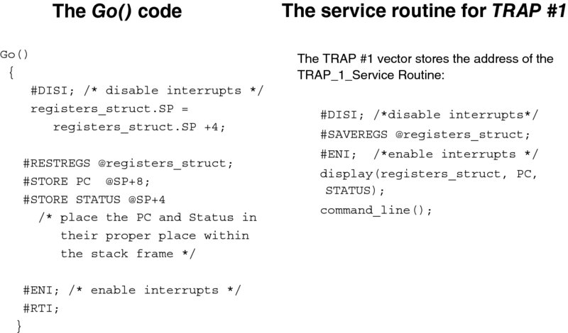
Figure 3.7 Go( ) and the interrupt service routines.
- Store the address of the pointer to the TRAP_1_Service_Routine( ) at the interrupt vector for the TRAP #1 instruction. (This location, which depends on a particular CPU, is supplied by the CPU manual.)
- Execute the TRAP #1 instruction, which will result in the execution of the TRAP_1_Service_Routine( ). The latter calls the command_line( ) procedure, which prompts the user for a command and then interprets it.
Now we can start debugging. Say we want a program, whose first instruction is located at memory address 300000, to stop when it reaches the instruction located at address 350000.
We type the following three commands:
>Register PC, 300000
>Set 350000
>Go
When the interpreter invokes Go( ), it first pops the stack to make up for the debugger's command-line procedure frame (With our design, we will never return from this call by executing RTP.). Then it transfers the register values stored in registers_struct to the CPU. The same task is repeated separately for the PC and the STATUS registers, whose values must be modified on the stack to build the proper stack frame. Finally, the RTI instruction is executed.
This will get the program moving. When it reaches the trapped instruction, our TRAP handler will be invoked. As a result, we will see the values of the registers and a prompt again. We can examine the memory, possibly change one thing or another, replace the trapped instruction, and maybe set another trap.
Note that the Go( ) procedure has, in effect, completed interrupt handling: the RTI instruction has not been part of the trap service routine. We can have more than one program in memory, and by modifying the registers appropriately, we may cause another program to run by “returning” to it.
This is a dramatic point: we have all we need to run several processes concurrently!
To do so, we allocate each process appropriate portions of memory for the stack and for the rest of the process's memory, called a heap, where its run-time data reside. We also establish the proper stack frame. In the latter, the value of the PC must point to the beginning of the process's code, and the value of the SP must point to the process's stack. (The rest of the registers do not matter at this point.) We only need to execute the last three instructions of Figure 3.5; the magic will happen when the RTI instruction is executed!9
And thus, with the CPU described so far—however simple it may be—it is possible to make the first step toward virtualization, that is multi-processing. With this step, multiple processes (possibly belonging to different users) can share a CPU. This is the view of multi-processing “from outside.” The “inner” view—a process's view—is that the process is given its own CPU as a result.
The perception of owning the CPU is the first step toward virtualization. But the ideal of “being virtual” cannot quite be achieved without virtualizing memory, that is making a process “think” that it has its own full memory space starting from address 0.
These two aspects—the CPU and memory virtualization—are addressed in the next two sections. It turns out that adding new capabilities requires changes to the architecture. As the needs of multi-processing become clear, our CPU will further evolve to support them.
3.2.5 Multi-processing and its Requirements—The Need for an Operating System
Let us consider the case of only two processes. To keep track of their progress, we create and populate a data structure—an array, depicted in Figure 3.8—each entry of which contains:
- The complete set of values of a process's registers (with the PC initially pointing to the respective program's code segment, and the SP pointing to the stack).
- The state of the process, which tells us whether the process is (a) waiting for some event (such as completion of I/O), (b) ready to run, or (c) in fact, running. Of course, only one of the two processes can be in the latter state. (For this matter, with one CPU, only one process can be running, no matter how many other processes there are.)
- The segment and page table pointers (see Section 3.2.6), which indirectly specify the address and size of the process heap memory (that is, the memory allocated for its global variables).
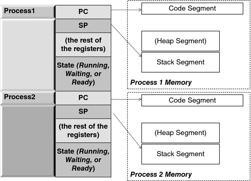
Figure 3.8 The process table.
It is easy to imagine other entries needed for housekeeping, but just with that simple structure—called the process table—we can maintain the processes, starting them in the manner described at the end of the previous section and intervening in their lives during interrupts.
It is also easy to see that two, for the number of processes, is by no means a magic number. The table can have as many entries as memory and design allow.
The program that we need to manage the processes is called an operating system, and its objectives set a perfect example for general management: the operating system has to accomplish much but whatever it does must be done very fast, without noticeably interfering with the lives of the processes it manages.
The major events in those lives occur during interrupts. To this end, the operating system at this point is but a library—a set of procedures called from either the main line of code or the interrupt service routines. Incidentally, the system could even allocate CPU fairly equally among the processes by processing clock interrupts and checking whether a CPU-bound process has exceeded its share of time—the time it is allowed to own the CPU. (This share is called quantum. Its value, assigned at the configuration time, allows us to support the CPU virtualization claim: that a CPU with a speed of θ Hz,10 when shared among N processes, will result in each process being given a virtual CPU of θ/N Hz.)
Overall, the operating system is responsible for the creation and scheduling of the processes and for allocating resources to them. In a nutshell, this is achieved by carefully maintaining a set of queues. In its life, a process keeps changing its state. Unless the process is executing, it is waiting for one thing or another (such as a file record to be read, a message from another process, or a CPU—when it is ready to execute). The operating system ensures that each process is in its proper queue at all times. We will keep returning to the subject of operating systems, but this subject requires an independent study. Fortunately, there are excellent and comprehensive textbooks available [6, 7], which we highly recommend.
Getting back to the architecture at our disposal, we note three fundamental problems.
The first problem is that a user program must somehow be aware of specific addresses in memory where its code and data reside, but these addresses are never known until run time. We defer the resolution of this problem until the next section.
The second problem is that, at the moment, we have no way to prevent a process from accessing another process's memory (whether for malicious reasons or simply because of a programmer's error). Even worse, each process can access the operating system data too, because at this point it is in no way different from the user data.
The third problem is that we cannot prevent processes from executing certain instructions (such as disabling interrupts). If a user can disable interrupts in its program, the computer may become deaf and mute. Incidentally, this is a fine—and extremely important—point that needs some elaboration. Since the system code we discuss is only a library of system routines, it is being executed by one or another process. Indeed, either the process's program calls the respective library procedure directly or it is called during the interrupt—which is processed on the interrupted process's stack. Yet, it is intuitively obvious that only the system code, not the user program code, should be allowed to disable the interrupts. Hence the problem here, again, is that the user code so far has been indistinguishable from the system code.
The last problem has been addressed by recognizing that the CPU must have (at least) two modes of execution: the user mode and the system mode. The former is reserved for user programs and some non-critical system code. The latter is reserved for the critical operating system code (or kernel). With that, certain instructions must be executed only in the system mode. Correspondingly, both CPUs and modern operating systems have evolved to support this principle.
How can we implement it? We observe that the system code has been invoked when either:
- It is called explicitly from a user's program, or
- An interrupt (or an exception) has occurred.
To ensure that system processing is entered only through a designated gate, we postulate that all system calls be made via an exception—by executing the TRAP instruction. (Now we have fulfilled the promise made earlier to explain the further use of this instruction!) Every procedure that needs access to system resources or external devices must do so. This reduces the first case above to the second: Now the system code can be invoked only via an interrupt or exception.
We further postulate that the CPU is (1) to start in the system mode and (2) automatically enter the system mode whenever an interrupt or exception is processed. With that, the CPU may switch from system into user mode only when explicitly instructed (by the kernel) to do so.
In what follows, the main idea is to ensure that what a process can do in the user mode is limited only by what can affect this very process—and no other process or the operating system. To achieve that, we first need to make the CPU aware of what code it is running—the user code or the operating system code. Second, we need to restrict the actions that can be performed in the user mode. Again, the guiding principle is that the CPU starts in the system mode and switches to the user mode only when explicitly instructed to do so. While it is in the user mode, the CPU's actions must be restricted.
We make the CPU aware of the operating mode by introducing a new mode flag in the STATUS register, which is a bit indicating the system mode (when set) or the user mode (when reset). Figure 3.9 depicts the state machine that governs the transitions between the system and user states.
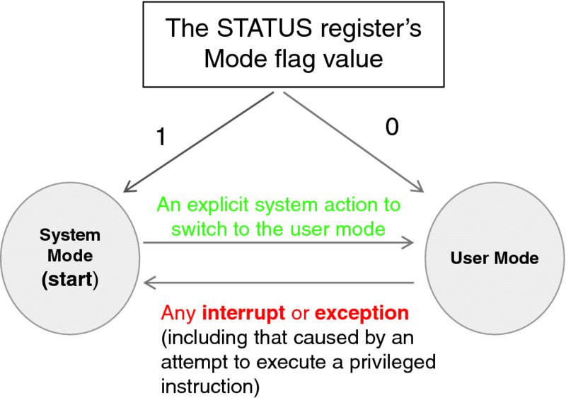
Figure 3.9 The CPU mode state machine.
We further modify our CPU by adding a new stack pointer register, so we have two now—one (called the system SP) for the system mode and the other (called the user SP) for the user mode. Figure 3.10 illustrates this modification. The register name (or rather encoding) in instructions intentionally remains invariant over the choice of register, but the CPU knows which register to use because of the mode flag in the STATUS register.
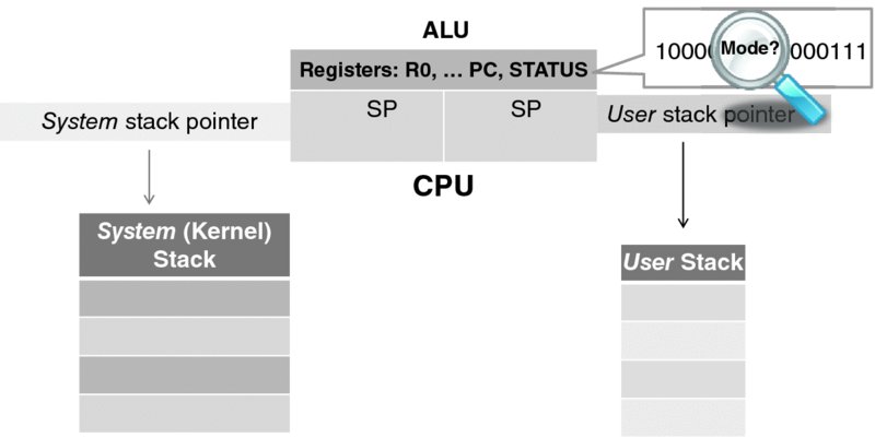
Figure 3.10 The modified CPU and the two process stacks.
With that change, an operating system can now maintain two stacks—one for executing the system code and one for executing the user code. The notion of maintaining two stacks may appear stunningly complex at first, yet it actually simplifies the operating system design. It has been implemented with great success in the Unix operating system, with the design explained in Bach's prominent monograph [8]. (The attentive reader may ask right away which stack is used to save the CPU state at interrupt. The answer is: the system stack. The first thing that happens at interrupt or exception is that the CPU switches to the system mode, which automatically activates the system stack pointer.)
Next, we introduce privileged instructions: those instructions that can be executed successfully only when the CPU is in the system mode. RTI, DISI, and ENI are the first three instructions in this set. The reason for RTI being privileged is that it causes restoration of the STATUS register, and hence may cause a transition to the user mode. As we postulated earlier, this transition may happen only as a result of the system code execution.
Now, DISI and ENI are mnemonics for operations on a flag in the STATUS register. With our CPU, any instruction (such as logical AND, OR, or LOAD) that alters the value of the STATUS register is declared privileged. Similarly, any instruction that changes the value of the system stack pointer is privileged by design, since the user code has no way even to refer to the system SP.
The context in which an instruction is used is an important factor in determining whether it needs to be privileged or not.
To this end, we postulate that all instructions that deal with the I/O access (present in some CPUs) are privileged. We will discuss handling privileged instructions in Section 1.2.7; first we need to understand the issues in virtual memory management, which necessitates a whole new class of privileged instructions.
3.2.6 Virtual Memory—Segmentation and Paging
The modern notion of memory being virtual has two aspects. First, with virtual memory a process must be unaware of the actual (physical memory) addresses it has been allocated. (Instead, a process should “think” that it and its data occupy the same addresses in memory every time it runs.) Second, the process must “think” that it can actually access all addressable memory, the amount of which typically far exceeds that of the available physical memory. (It is still uncommon, to say the least, to expect a computer with 64-bit addressing to have two exabytes—2 × 1018 bytes—of actual memory!)
Except for the need for some advanced hardware address-translation mechanism, common to enabling both aspects, there are significant differences in their respective requirements.
We start with the first aspect. Even in the case of a two-process system, as Figure 3.8 demonstrates, it is clear that the segments allocated to them will have different addresses. Yet, with our CPU, each instruction has its pre-defined address in memory, and the memory allows absolute addressing too. And so, if the code of Process 2 has an instruction LOAD R1, 30000 but the data segment for this process starts at location 5000, the instruction must somehow be changed. One potential approach here is to effectively rewrite the program at load time, but this is impracticable. A far better approach is to employ a tried-and-true electrical engineering midbox trick, depicted in Figure 3.11. This figure modifies Figure 3.2 with a translation device, called a Memory Management Unit (MMU), inserted between the CPU and the bus. This device has a table that translates a logical (i.e., virtual) address into an actual physical address. (In modern CPUs, this device has actually been integrated into the CPU box.)
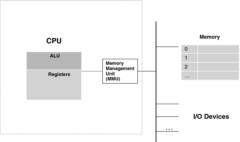
Figure 3.11 Introducing the MMU.
Suppose a process has been programmed (or compiled) with the following assumptions:
- its code starts at location x;
- the user stack starts at location y;
- the system stack starts at location z; and
- the heap starts at location t.
Each of these is a contiguous piece of memory—a segment. In fact, even smaller segments can be thought of and used in practice. For instance, it is very convenient to put all initialization code in one place in memory (which can later be reused after initialisation is completed). Segments are enumerated and referred to by their numbers.
At the time of loading the process, the operating system brings its code into location x′, while allocating both stack segments and the heap memory segment starting at addresses y′, z′, and t′, respectively. A segment number is an index into the MMU table. One entry in this table is the segment base register (e.g., x′ or y′), which the operating system fills out. The MMU has the circuitry to translate a logical address into a physical address. Thus, the logical address a in the code segment gets translated into a − x + x′, which is the sum of the segment base register, x′, and the offset within the code segment, (a − x). This translation can be performed very fast by hardware, so its effect on timing is negligible.
The MMU also helps to ensure that no process can read or write beyond the segment allocated to it. For that there is another entry in the MMU table: the size of the segment memory which the operating system has allocated. Continuing with the example of the above paragraph, if X is the size of the code segment, then the inequality a − x < X must hold for each address a. If this does not happen, an exception is generated. Again, the comparison with a constant is performed so fast by the MMU circuitry that its effect is negligible.
Figure 3.12 summarizes the MMU address translation process. We should add that an MMU can do (and typically does) much more in terms of protection. For example, in the segment table it may also contain the flags that indicate whether a segment is executable (thus preventing accidental “walking over” the data, as well as preventing attacks where malicious code is placed into a data segment so as to be executed later). Additional flags can indicate whether it is read only, can be shared, and so on. This allows much versatility. For example, an operating system library may be placed into a read-only code segment available to all processes.

Figure 3.12 Segmentation: The MMU translation processing.
The MMU is typically accessed through its registers. It hardly needs an explanation why only privileged instructions may access the MMU entries!
The second aspect of memory virtualization—that is, creating the perception of “infinite” memory—is much more complex, and we will describe it only schematically here. Either of the operating system books [7, 8] does an excellent job of explaining the details.
To begin with, the technology employed here also solves another problem—memory fragmentation. With several processes running, it may be impossible for the operating system to find a contiguous memory segment to allocate to yet another process; however, cumulatively there may be enough “holes” (i.e., relatively small pieces of unused memory) to provide enough contiguous memory, should these “holes” be merged into a contiguous space.
To achieve that, another type of MMU is used. It works as follows. The logical memory is treated as an array of blocks called pages. All pages have the same size (which is always chosen to be an exponent of 2, so that with the maximum addressable memory n and page size f there are exactly n/f logical pages). Similarly, the actual physical memory is treated as an array of physical frames, all of the same size, which is the same as the page size. Each process has a page table, which—for the moment—maps each logical page into a corresponding frame in physical memory. The MMU uses this table to perform the translation.
Figure 3.13 demonstrates a case where, with the help of the MMU, scattered pieces of memory make up what appears to a process to be a contiguous segment. (The page size is actually a fragmentation unit. In other words, no memory fragment larger than or equal to the page size is left unused.)
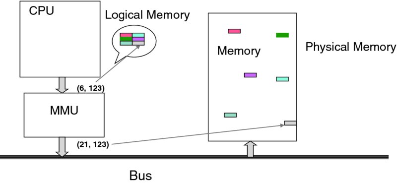
Figure 3.13 Paging—establishing contiguous memory.
Suppose that a process needs to access what it thinks is address ![]() As the figure shows, this address is interpreted as belonging to page number 6, with offset 123. The MMU table maps page 6 into the physical frame 21. Ultimately, the address is translated to
As the figure shows, this address is interpreted as belonging to page number 6, with offset 123. The MMU table maps page 6 into the physical frame 21. Ultimately, the address is translated to ![]() which is the actual physical location.
which is the actual physical location.
Providing contiguous memory is a fairly simple feature. The most ingenious feature of paging though is that it supports the case when the number of frames in the memory is fewer than the total number of pages used by all active processes. Then, even the logical address space of a single process may be larger than the whole physical memory! To achieve that, the operating system maps the process memory to a storage device (typically, a disk). As Figure 3.14 shows, some pages (called resident pages) are kept in the physical memory, while other pages are stored on the disk. When a logical address that corresponds to a non-resident page is referenced by a process, it must be brought into physical memory.
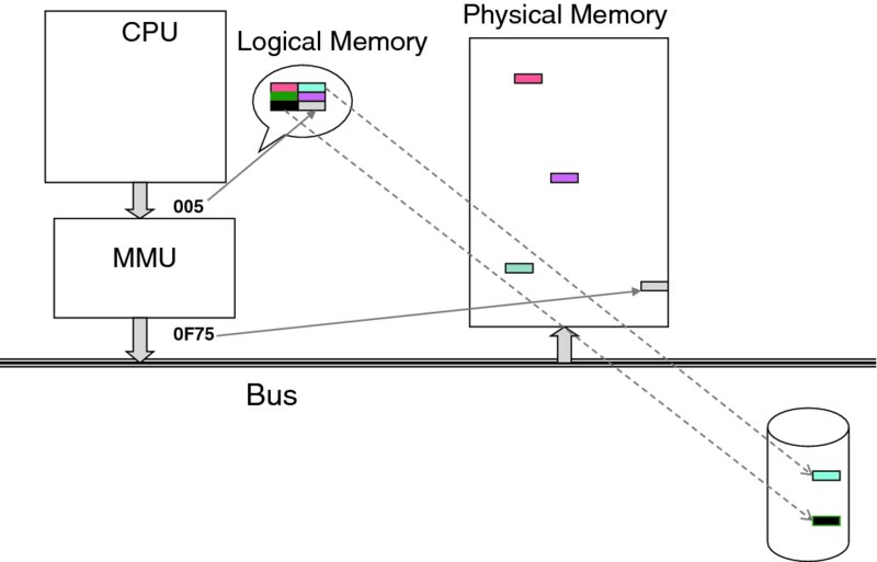
Figure 3.14 Storing pages on the disk to achieve the “infinite” memory illusion.
Of course, when all the frames in memory are occupied, it is a zero-sum game: if a page is to be brought into memory, some other page must be evicted first. The choice of the page to be evicted is made by a page-replacement algorithm employed by the operating system. This choice is crucial to performance, and hence substantial research into the problem has been carried out over a period of decades. Its results, now classic, can be found in any operating systems text.
Incidentally, the actual memory/storage picture is not just black-and-white—that is, fast but relatively small and volatile RAM and relatively slow but voluminous and long-lasting disk storage. In Chapter 6 we introduce and discuss different types of storage solution, which together fill in the spectrum between the two extremes and establish the hierarchy of memory.
The page table depicted in Figure 3.15 provides a few hints as to the translation implementation. The left-most bits of a virtual address provide the logical page number; the rest is the offset, which remains invariant. If a page is resident, as indicated by the respective flag in the table, the translation is straightforward (and rather fast). If it is non-resident, the MMU generates an exception—the page fault.
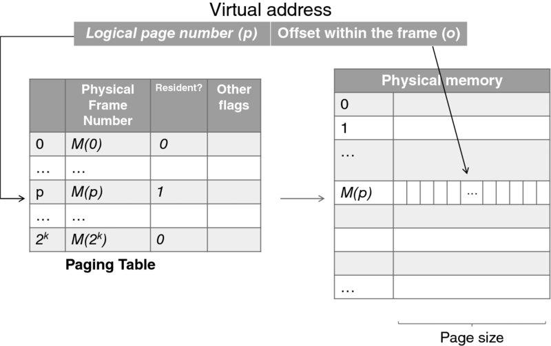
Figure 3.15 Page table and virtual address in-memory translation.
To process a page fault, the operating system needs to find a page to evict. (The page-replacement algorithms use other flags stored at the page table.) Then, the page to be evicted may be written to the disk and, finally, the page that is waiting to be referenced will be read from its place on the disk into the memory frame. If this looks like a lot of work, it is! But with what has been learned about paging, it is made rather efficient. While virtual memory is slower than real memory, complex heuristics-based algorithms make it not that much slower. It is also worthy of note that process page tables can grow large—much larger than the extent an MMU may fit in, which brings into place additional machinery employed in this type of translation.
Again, just as segment tables do, page tables also employ memory protection—a page may be executable only, read only, writable, or any combination of these. And, as in the case of segment tables, all instructions that are involved in changing page tables are privileged.
A final note to relate different pieces of this section: segmentation can be combined with paging. For instance, each segment can have its own page table.
3.2.7 Options in Handling Privileged Instructions and the Final Approximation of the CPU Loop
An important question to ask at this point is what the CPU does when it encounters a privileged instruction while in the user mode. (How could a privileged instruction end up in a user's program? Of course no legitimate compiler will produce it, but it may end up there because of an assembly programmer's mistake or because of malicious intent. And it will end up there because of full virtualization—the subject we explore in Section 3.3.)
All existing CPUs deal with this situation in one of two ways. When a CPU encounters a privileged instruction while in the user mode, it either (1) causes an exception or (2) ignores the instruction altogether (i.e., skips it without performing any operation—just wasting a cycle).
Either way, it is ensured that a user program will be incapable of causing any damage by executing a privileged instruction; however, case 2 causes problems with virtualization. We will dwell on this problem later, when studying hypervisors.
By design, our little CPU,11 which we have been developing for quite a while now, does cause an exception when it encounters a privileged instruction while in the user mode. In this way, the CPU provides a clear mechanism to indicate that something went wrong. It also helps improve security. As far as security considerations are concerned, detecting an attempt at gaining control of the system may be essential for preventing other, perhaps more sophisticated, attempts from the same source. Ignoring a “strange” instruction does not help; taking the control away from the program that contains it does.
With that, we arrive at the third—and final—approximation of the CPU loop, shown in Figure 3.16. The first major change, compared with earlier versions, is that each instruction is examined at the outset. If it cannot be recognized, or has wrong parameters, or if it is inappropriate for the present mode (i.e., if it is a privileged instruction and the CPU is running in the user mode), an exception is raised. Another change is that when the CPU starts processing an interrupt or an exception, it changes to the system mode, and also switches to the system stack. (As far as timing is concerned, the STATUS register is saved before the CPU mode is switched, of course. So the CPU could return to the mode in which it was interrupted.) Again, the registers are saved at the system stack—not the user stack—which is yet another security measure. With good design, the user code can neither touch nor even see the system data structures.
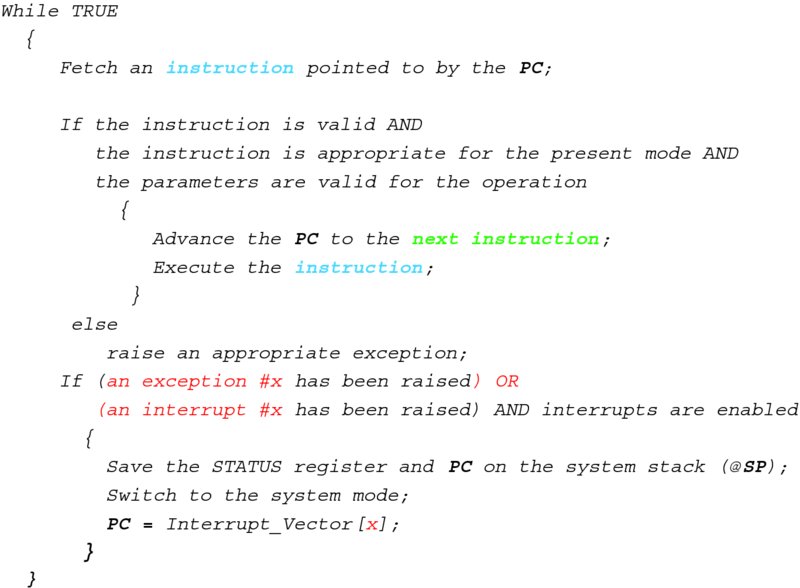
Figure 3.16 CPU loop—the final version.
3.2.8 More on Operating Systems
The CPU that we have constructed so far supports virtualization inasmuch as each process can “think” of owning the whole CPU (even though a slower one), all I/O devices, and infinite, uniformly addressed memory. The physical machine is governed by the operating system software, which creates and maintains user processes. An operating system is characterized by the services that it provides.
We have addressed such services as CPU access and memory management. The latter extends to long-term memory—the establishment and maintenance of a file system on a disk. A disk is just one of the I/O devices managed by an operating system. A monitor, keyboard, and printer are examples of other devices. Yet another example is a network drive. A process gets access to a device only through the operating system.
While a process has seeming ownership of the CPU, memory, and devices, it needs to be aware of other processes. To this end, all modern operating systems have mechanisms for interprocess communication, which allows processes to exchange messages. Combined with data communications, this capability enables communications among processes that are run on different machines, thus creating the foundation for distributed computing.
The services are built in layers, each layer serving the layer immediately above it. If the file system service is implemented on top of the data networking service, then it is possible to map a process's file system across disks attached to different computers, with the process never being aware of the actual location of the device and consequently the location of a specific file record.
A process requests an operating system service via a system call. This call—to a programmer—is just a procedure call. Invariably, the corresponding procedure contains a trap instruction, which causes a break in process execution. Figure 3.17(a) contains pseudo-code for an example Service_A routine. All it does is push the Service_A mnemonics on the user stack and pass control to the system via TRAP 1.
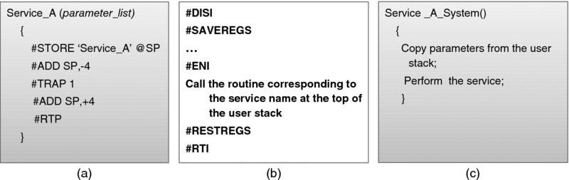
Figure 3.17 System call processing: (a) the Service_A routine—user part; (b) the TRAP 1 service routine; (c) the Service_A routine—system part.
The process will resume when the TRAP 1 exception is processed, as depicted in Figure 3.17(b). The handler reads the top of the process's stack to determine that service A is requested and then calls the Service_A_System routine. As shown in Figure 3.17(c), the latter proceeds in the system mode, likely calling other system procedures. When finished, it returns to the exception handler of Figure 3.17(b), which at the end passes control back to the user program code via the RTI instruction. (You may remember that the value of the STATUS register, with the mode flag indicating the user mode, was saved at the time of the interrupt. The switch to the user mode is effected merely by restoring that value.)
It is important to understand that a user process goes through a sequence of instructions that alternate between the user program code and the system code; however, the user program has no knowledge or control of the system data structures or other processes' data (unless, of course, other processes intentionally share such data).
We briefly note that when a service routine starts an I/O operation, it typically does not wait until the operation completes. Instead, it parks the process in a queue for a specific event from this device and passes control to a scheduler so that another process can run. To this end, a time-slice interrupt may result in exactly the same treatment of the interrupted process, if the operating system determines that the process's quantum has been reached. In this way, the operating system can ensure that the CPU has been allocated fairly to all processes.
At this point it is appropriate to explain the difference between the terms process and thread. A process is assigned resources: its memory space, devices, and so on. Initially, these resources were associated with a single thread of control. Later, the term process became associated only with the address space and resources—not the thread of execution. With that, multiple tasks (threads) can execute within a process, all sharing the same resources. Sometimes, threads are also called light-weight processes, because context switching of threads is a much less involved procedure (no need to reload page tables, etc.) than that of processes. Unfortunately, this terminology is not used consistently.
The evolution of the operating systems has been influenced by two factors: application needs and hardware capabilities (and, consequently, hardware price). When considering the implementation specifics, there is still a gray area within which it is impossible to postulate whether a given function is performed in hardware or in the operating systems.
Advances in data networking have resulted in distributing the operating system functions among different nodes in the network. This has actually been a trend in the 1990s and 2000s, until Cloud Computing took over. With that, the trend seems to be reversed (with effort concentrating on one—virtual—machine), while advancing in spirit (the virtual machine can easily migrate across the network from one machine to another).
Throughout the history of operating systems the general problem of security (as well as the narrower problem of privacy) has been addressed constantly. Interestingly enough, it was addressed even when it was a non-issue—that is, in the absence of networking and at a time when very few people even had access to computers. The history of operating systems has demonstrated though what the overall history of mankind has also demonstrated: the best idea and the best design do not necessarily win. To this end, MIT's Multiplexed Information and Computing Service (Multics) [10] operating system's feature set has never ended up fully in a ubiquitous commercial product, although Multics has influenced the design of several operating systems—most notably the Unix operating system.
Multics took security seriously. Robert Graham, a Multics contributor and a visionary, wrote in his seminal 1968 paper [11] (which very much predicted the way things turned out to be almost half a century later): “The community of users will certainly have diverse interests; in fact, it will probably include users who are competitive commercially. The system will be used for many applications where sensitive data, such as company payroll records, will need to be stored in the system. On the other hand, there will be users in the community who wish to share with each other data and procedures. There will even be groups of users working cooperatively on the same project. … Finally, there will be public libraries of procedures supplied by the information processing utility management. Indeed, a primary goal of such a system is to provide a number of different users with flexible, but controlled, access to shared data and procedures.”
Graham's design, which has been implemented in Multics, specified protection rings. We start with a simplified scheme, as depicted in Figure 3.18. Revisiting the segment table discussion of Section 3.2.6, we can further refine the permission to access a segment.
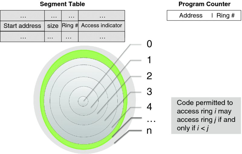
Figure 3.18 Graham's security rings (hardware support).
The decision to focus on a per-segment rather than a per-page protection scheme was deliberate. In Graham's lucid prose: “a segment is a logical unit of information of which a user is cognizant,” while “a page is a unit of information which is useful to the system for storage management and is thus invisible to the user.” The idea of the protection scheme is based on the military principle of need to know, defined by the respective clearance level. At a given clearance level, those who have it may access the information at any lower clearance level but not the other way round; hence the representation of the privilege levels as a set of concentric rings. The smallest ring (ring 0) has the highest privilege level. (The graphical significance of this is that the higher the privilege level the smaller the set of those who are granted access at this level, so smaller circles delineate rings with higher privilege levels.)
Graham presents two models in [11]. The first is simple and straightforward; the second is more complex as it provides an optimization.
Both models require a change to the segment table. The access indicator field for both models contains four independent flags:
- User/System flag—indicates whether the segment can be accessed in the user mode.
- Read/Write flag—indicates whether the segment can be written to.
- Execute flag—indicates whether the segment can be executed.12
- Fault/No fault flag—indicates whether accessing the segment results in an exception no matter what (an extra level of protection, which overwrites all other flags).
The PC register is augmented with the ring number indicating the privilege level of the code. In addition, each segment table entry is augmented by a reference to the ring structure, but here the models differ.
In the first model, each segment is now assigned its ring number to indicate its privilege, as shown in the segment table entry. Note that this scheme results in different privileges assigned to disjoint sets of segments.
Let us consider a code segment. If the segment's access ring value is i, the code in the segment may access only a segment whose access ring value is j > i. (Of course, this is only the first line of defense. Access is further restricted by the values of the access indicator flags.) Jumps out of a segment require special intervention of the system, so all of them cause an exception.
While this model works, Grahams shows that it can be made more efficient if the requirement that the rings be disjoint is relaxed to allow execution of shared routines at the privilege level of the caller—but not higher. This observation results in the second model, depicted in Figure 3.19.
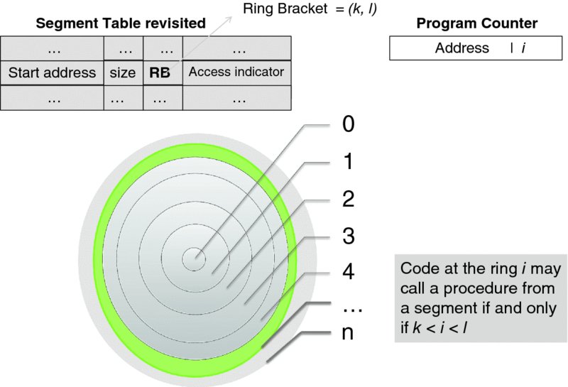
Figure 3.19 Optimization with non-disjoint security rings.
Here, the ring number in a segment table entry is replaced with two numbers, which respectively indicate the lower and upper bound of the segment's ring bracket. All code in a segment—intended to be a procedure library—is assigned to the consecutive segments in the bracket. Thus, when a procedure executing at the privilege level i calls a procedure whose access bracket is [k, l] no exception occurs as long as k < i < l. A call outside the bracket limits results in an exception.
So far we have considered only the transfer of control among code segments, but the use of ring brackets can be extended further to the data segments as follows. If a data segment has a ring bracket [k, l] then an instruction executing at the privilege level i may
- write to this segment as long as it is writable and i ⩽ k (i.e., the instruction has higher privilege level than the segment) or
- read this segment if k < i ⩽ l.
The instruction may not access the segment at all if i > l.
Multics specifies eight protection rings. The number of rings is restricted by hardware. Back in the 1980s, the Data General Eclipse MV/8000 CPU had a three-bit ring indicator in the PC. (See [12] for a well-written story about this.)
All that development was foreseeing the future—which is happening right now. The renewed interest in protection, in view of virtualization, has made many computer scientists nostalgic for the 1970s and 1980s.
On this note, we conclude our primer. To summarize:
- A process as a unit has its own virtual world of resources: a CPU, an “infinite” memory, and all I/O devices.
- A process relies on an operating system—the government of a physical machine, which ensures that all processes are treated fairly.
- The operating system kernel is the only entity that can execute privileged instructions. The kernel is entered as a result of processing an interrupt or an exception (including a trap).
- A physical machine may execute more than one process.
- A process may be aware of other processes, and it may communicate with them.
The next section explains how this can be taken to the next level of abstraction so as to develop a virtual machine of the type shown in Figure 3.1.
3.3 Virtualization and Hypervisors
Let us revisit our objectives.
By introducing virtualization we want, first of all, to save the cost—in terms of space, energy, and personnel—of running several machines in place of one. An increasingly important aspect here is the green issue: as a rule, one machine uses less energy than several machines.
Yet another objective of virtualization is to increase CPU utilization. Even with multi-processing, a CPU is almost never fully utilized. Long before the term “Cloud Computing” was coined, it was observed that the machines that ran web servers had low CPU utilization. Running several servers on their respective virtual machines, now grouped on one physical machine that used to run a single server, allowed them to get good use of this single machine while saving money on energy and hardware.
Other objectives include cloning the computing environment (such as a server) for debugging, at low cost; migrating a machine—for instance, in response to increasing load; and isolating an appliance (again a server is a good example) for a specific purpose without investing in new hardware.
As far as security is concerned, isolation is a boon for analyzing an unknown application. A program can be tested in a virtual machine, and consequently any security risk it poses will be isolated to this virtual machine. Granted, this wonderful feature depends on the security of the hypervisor itself, which we address in the last section of this chapter.
In our opinion, the very emergence of Cloud Computing as the business of providing computing services as a utility has also been an outcome (rather than an objective) of virtualization. Of course, it was not virtualization alone but rather a combination of virtualization and availability of fast networks, but we feel that virtualization technology has played a major role here.
We start with a general assumption—based on the traditional CPU architectures—that an operating system kernel by itself cannot create an isolated virtual machine. With the fairly recent CPU virtualization extensions, however, this assumption no longer holds, and later we will review a special case of the Kernel-based Virtual Machine (KVM) hypervisor, which—as its name suggests—is indeed kernel based.
From the onset of virtualization, the software charged with creating and maintaining virtual machines has been called the Virtual Machine Monitor (VMM) or hypervisor. Both terms are used interchangeably in the literature; in the rest of this book, we will use only the latter term. The virtual machine environment is created by a hypervisor.
3.3.1 Model, Requirements, and Issues
The classical abstract model for addressing the resources needed by processes executing on virtual machines, as presented in [13], has been known for over 40 years. In this model, two functions are employed—one visible to the operating system and the other visible only to a hypervisor. The former function maps process IDs into (virtual) resource names; the latter one maps virtual resource names into physical resource names. Such mapping is recursive, allowing several virtual machine layers on top of physical hardware. Whenever a fault (i.e., a reference to an unmapped resource) occurs, an exception results in passing control to the next-layer hypervisor. This model has provided a foundation for the systematic study and implementation of virtualization.
A major follow-up was the work [14], which has become a classic and made the names of its authors—Dr. Gerald Popek and Dr. Robert Goldberg—forever associated with virtualization, as in “Popek and Goldberg virtualization requirements.” It is worth examining this remarkable paper in some detail.
To begin with, the major task of the paper was to state and demonstrate “sufficient conditions that a computer must fulfill in order to host” a hypervisor. To this end, the authors have developed a formal model of a machine and proved their conclusions mathematically. The model is an abstraction of the third-generation CPU architecture; IBM 360, Honeywell 6000, and DEC PDP-10 are specific examples, as is the CPU we have developed earlier in this chapter. The model does not take interrupts into account, as these are non-essential to the subject, but traps are modeled thoroughly.
The paper outlines the three essential characteristics of a hypervisor (the authors used the term VMM): “First, the VMM provides an environment for programs which is essentially identical with the original machine; second, programs run in this environment show at worst only minor decreases in speed; and last, the VMM is in complete control of system resources.”
The first characteristic, often referred to as the fidelity requirement, states that a program run on a virtual machine must produce the same result as it would produce running on a real machine.
The second characteristic results in the efficiency requirement: software emulation of CPU instructions is ruled out in favor of their direct execution by the “hard” CPU. The authors voice this requirement by stating that a “statistically-dominant” subset of instructions must be executed directly by a real processor.
The third characteristic is translated into the following resource control requirements:
- No program running on a virtual machine may access resources that were not explicitly allocated to it by a hypervisor.
- A hypervisor may take away from a virtual machine any resource previously allocated to it.
Now we can introduce the formal model of [14]. (This part can be skipped without jeopardizing the understanding of either the principles or the results of the work.) The model is based on the definition of the state of the machine S = 〈E, M, P, R〉 as a quadruple, where E is the state of memory, M is the CPU mode (i.e., user or system mode), P is the value of the PC, and R is the “relocation-bound register.” (In the case of our CPU, this is actually the whole MMU, but early third-generation CPUs had effectively only one segment and consequently only one relocation register.) The model makes the memory locations E[0] and E[1] the effective stack for saving the 〈M, P, R〉 triplet. The instruction i can be viewed as a mapping of the state space into itself, so we can write
The instruction is said to trap if the storage is left unchanged, except for the top of the stack:
An instruction is said to memory-trap if it traps when accessing out-of-bound memory.
With that, the instructions are classified as follows:
- An instruction is called privileged if it does not memory-trap, but traps only when executed in user mode.
- An instruction is called control-sensitive if it attempts to change the amount of memory available or affects the CPU mode.
- An instruction is called behavior-sensitive if its execution depends on the value of controls set by a control-sensitive instruction. The examples provided by the authors are (1) the IBM 360 Load Real Address (LRA) instruction, which is location-sensitive and (2) the PDP-11/45 Move From Previous Instruction Space (MFPI) instruction, which is mode-sensitive. (The latter instruction is one of that machine's four instructions copying on the current stack the data from the operand address in the previous address space as indicated by the CPU mode. The CPU we have defined does not have such a capability.)
- An instruction is called sensitive if it is either behavior-sensitive or control-sensitive. Otherwise, it is called innocuous.
Sure enough, formalizing the definition of the sensitive instructions involves a considerable amount of notational complexity, which the authors call an “unfortunately notation-laden tangent.” The theory developed based on this notation allows us to prove formally that a hypervisor can be constructed if all sensitive instructions are privileged, which is the main result of the paper.
With that, the hypervisor is constructed as depicted in Figure 3.20.
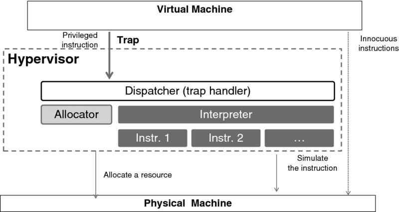
Figure 3.20 Hypervisor structure—after Popek and Goldberg. Data from [14].
All innocuous instructions in the code executed by the virtual machine are executed immediately by the CPU of the physical machine. An attempt to execute a privileged instruction results (by definition) in a trap, for which the Dispatcher is the service routine. If an instruction requires resource allocation, the dispatcher calls the Allocator. Ultimately, a trapped instruction is emulated by the Interpreter, which is but a library of emulation routines, one for each instruction.
The model of [14] was not specifically concerned with time sharing, although the authors point out that the CPU itself is a resource that the Allocator can take care of.
Indeed, today hypervisors act in a time-shared environment, as depicted in Figure 3.21.
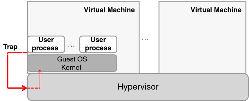
Figure 3.21 General virtualization architecture.
In this architecture, a hypervisor is responsible for maintaining the virtual machines and allocating resources to each such machine, in accordance with the three virtualization requirements.
Each virtual machine runs its own operating system (called a guest operating system), which in turn handles the user processes. A hypervisor gets all the interrupts and exceptions. Among the latter there are traps that correspond to system calls.
Some interrupts (such as alarm interrupts that deal with time sharing among multiple machines) are handled by the hypervisor itself, with the result that a virtual machine that has exceeded its time quantum is stopped, and the CPU is given to another virtual machine.
All the interrupts and exceptions that are specific to a virtual machine, including the system calls that emanated from this machine's user processes, are passed to the guest operating system.
But where does the hypervisor run? So far, we have assumed that it runs directly on the physical machine. Such hypervisors are called Type-1 (or, sometimes, bare-metal) hypervisors. In contrast, a hypervisor that is running on top of an operating system is called a Type-2 hypervisor. This classification is depicted in Figure 3.22.
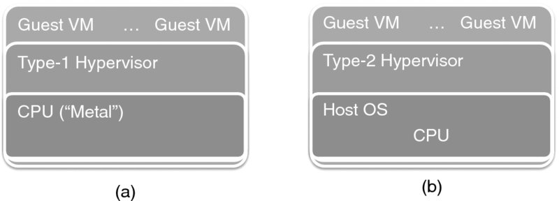
Figure 3.22 Type-1 and Type-2 hypervisors.
We will return to this taxonomy when considering specific case studies later in this chapter.
So far, we have been concentrating only on CPU virtualization issues. Needless to say, other virtualization elements—such as the virtualization of I/O device access—are by no means trivial, especially when real-time operation is concerned. As far as memory virtualization is concerned, even though it has been solved by operating systems at the process level, this turns out to be another non-trivial issue because of the necessity for a hypervisor to maintain its own “shadow” copies of page tables.
Still, the hardest problem is presented by those CPUs that are non-virtualizable in Popek and Goldberg's terms. Of these, the one most widely used is the x86 processor.
3.3.2 The x86 Processor and Virtualization
This workhorse of servers and personal computers alike has descended from the original Intel 8086 CPU, whose 1979 model (8088) powered the first IBM PC. At that time, the 8088's sharply-focused deployment strategy—personal computing—could not be concerned with virtualization. (What is there to virtualize on a machine designed for a single user?)
In contrast, the Motorola M68000 processor—a rival of the 8088, and the CPU of Apple Macintosh, Atari, and Amiga computers as well as the AT&T Unix PC workstation—had its architecture geared for virtualization from scratch. To this end, the M68000 processor had only one instruction that was non-virtualizable.
This instruction allowed it, while being executed in the user mode, to transfer the value of the STATUS register to a general register. In the CPU we developed earlier in this chapter, its equivalent is LOAD R1, STATUS. This instruction is behavior-sensitive in the Popek and Goldberg taxonomy because it allows a user program to discover which mode it is running in. The danger here is as follows: suppose a VM is running an operating system that is carefully designed with security in mind. One feature of this operating system is to halt its execution once it finds out that its kernel code runs in the user mode. Since the STATUS register has the mode flag, any operating system that implements this feature will halt.
With the goal for M68000 to equip micro- and even minicomputers that could run multiple operating systems, Motorola quickly remedied this problem. The M68010 processor, released in 1982, made this instruction trap when executing in the user mode, just as all other instructions did.13
As it happened, it was the x86 CPU—not the M68010—that took over the computing space, even though its instruction set, carefully developed with backward compatibility in mind, contained non-virtualizable instructions. For instance, the 32-bit processor instruction set of the Intel Pentium CPU has 17 instructions14 identified in [15] as non-virtualizable. These instructions fall into three classes. (Ultimately, it is the classes themselves that are important to understand in order to appreciate the problem because, while instructions vary among the processors, the classes are more or less invariant.) Let us look at the classes in the Intel Pentium example.
The first class contains instructions that read and write the values of the global and local segment table registers as well as the interrupt table register, all three of which point to their respective tables. A major problem is that the processor has only one register for each of these, which means that they need to be replicated for each virtual machine; mapping and special translation mechanisms are needed to support that. The respective effect on performance is obvious given that these mechanisms must be brought to motion on each read and write access.
The second class consists of instructions that copy parts of the STATUS register into either general registers or memory (including the stack). The problem here is exactly the same as in the case of the M68000 described above: The virtual machine can find out what mode it is running in.
The third class contains instructions that depend on the memory protection and address relocation mechanisms. To describe this class, it is necessary to introduce the code privilege level (CPL) in the x86 instruction set. There are four privilege levels, from 0 to 3, in descending privilege order, as shown in Figure 3.23. Therefore, code running at a higher privilege level has access to the resources available to code running at lower privilege levels; thus running at CPL 0 allows access to all the resources at CPL 1, CPL 2, and CPL 3. (In retrospect, in order to reflect the definition of higher privilege, it would have been more accurate to depict CPL 0 in the outer ring, CPL 1 in the next ring, and so on, but the long-standing practice is to assign the rings as depicted.) The practice of two-level operating systems has been to execute the system code at CPL 0 and the user code at CPL 3.
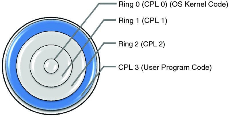
Figure 3.23 Intel privilege level rings.
Returning to the discussion of the third class of non-virtualizable instructions, it consists of instructions that reference the storage protection system, memory, or address relocation systems. Naturally, this class is rather large because even basic instructions (similar to our LOAD instruction) have variants in which segment registers are accessed.
But the instructions that check access rights or segment size from a segment table need to ensure that the current privilege level and the requested privilege level are both greater than the privilege level of a segment. That poses an execution problem, because a virtual machine does not execute at CPL 0.
Jumps, including procedure calls, pose further problems, in part because they are much more sophisticated than the JUMP and JPR instructions defined for our simplistic CPU earlier in this chapter. In the x86 architecture, there are two types of jump: near jumps and far jumps. Each of these two types is further subdivided into two classes: jumps to the same privilege level and jumps to a different privilege level. Ditto for procedure calls, and there are also task switches. As [15] explains, the problem with calls to different privilege levels and task switches is caused by comparing privilege levels of operations that do not work correctly at user level.
There is yet another class of non-virtualizable instructions—those that are supposed to be executed only in the system mode, which they do, but neither execute nor trap when an attempt is made to execute them in the user mode. These instructions are sometimes also called non-performing. The problem with these is too obvious to discuss it here.
We define full virtualization as a computation environment that is indistinguishable from that provided by a standalone physical CPU. One important characteristic of full virtualization is that it requires no modification to an operating system to be run by the virtual machine created in the environment. It is clear that full virtualization cannot be achieved on the unmodified x86 CPU.
Aside from emulating the CPU in software at every single instruction, which is impracticable, there are two major ways of dealing with non-virtualizable instructions, which we will discuss in the next section. Ultimately, this is all that can be done as far as software is concerned.
Yet, with the changes to x86 that have extended its virtualization capabilities, it has become possible to move on to the pure hardware-assisted virtualization approach. The only problem here is that the x86 processor has been manufactured by several companies—Intel, Cyrix, Advanced Micro Devices, and VIA Technologies among them—and while the behavior of the basic instruction set is standardized among the manufacturers, the virtualization mechanisms are not. Early approaches to virtualization extensions by Intel (VT-x) [16] and AMD (Pacifica and later AMD-V) [17] have been well described and compared in [18].
Although the extensions differ among manufacturers, their common capability is the provision of the new guest operating mode, in which software can request that certain instructions (as well as access to certain registers) be trapped. This is accompanied by the following two features (as summarized in [19]), which enable virtualization:
- Hardware state switch, triggered on a transition into and out of the guest operating mode, which changes the control registers that affect processor operation modes and the memory management registers.
- Exit reason reporting on a transition from the guest operating mode.
These features enable full virtualization. Before we return to this, let us address some generic approaches to non-virtualizable CPUs.
3.3.3 Dealing with a Non-virtualizable CPU
The common denominator of all solutions here is modification of the original binary code. The differences are in the timing of modifications to the code: whether these modifications take place at run time or before run time, via global pre-processing.
With binary rewriting, the virtualization environment software inspects, in near-real time, a set of instructions likely to be executed soon. Then it replaces the original instructions with traps, passing control to the hypervisor, which calls—and executes in the privileged mode—a routine that emulates the problematic instruction. This mechanism works exactly as the debugging tool that we described earlier in Section 3.2.4 (which was the reason for describing the tool in the first place), and, predictably, it may interfere with other debugging tools. As [20] points out, this potential interference necessitates storing the original code in place. This technique avoids pre-processing of the operating system binary code.
With paravirtualization, pre-processing is necessary. Pre-processing replaces all privileged instructions with so-called hypercalls, which are system calls that trap directly into the hypervisor. In effect, paravirtualization involves binary rewriting too, just that it performed prior to execution (rather than in real time) and on the whole of the operating system's binary code (rather than on a select subset of the instruction stream).
This provides a software interface to a virtual machine that differs from the interface to the actual hardware CPU interface. The modified guest operating system always runs in ring 1 now. Note that the application code remains unchanged as a result. Another advantageous feature of the paravirtualization technique is that it works (although slower than needed) even with full, hardware-assisted virtualization, so the virtual machine can easily migrate from a CPU that does not support full virtualization to one that does without any change. (There is a speed penalty though: in a paravirtualized system the system calls, destined for the OS kernel, first end up in a hypervisor, which then needs to interact back-and-forth with the kernel.)
There are other interesting advantages to paravirtualization. A notable one is handling of timers. All modern operating systems rely on clock interrupts to maintain their internal timers, a feature that is particularly essential for real-time media processing. For this, even an idle virtual machine needs to process the clock interrupts. With paravirtualization, the virtual machine code is changed to request a notification at the specified time; without it, the hypervisor would need to schedule timer interrupts for idle machines, which, according to the authors of [19], is not scalable.
Another advantage is in working with multi-processor architectures. Until now we have assumed there to be only one CPU in our simplified computer architecture, but this is not necessarily the case with modern machines. Conceptually, an operating system deals with multiple CPUs in the same way it deals with one; with modular design, it is just the scheduler and the interrupt handlers that need to be fully aware of the differences. Without delving into the depths here, we note that x86-based multi-processor architectures use the Advanced Programmable Interrupt Controller (APIC) for interrupt redirection in support of Symmetric Multi-Processing (SMP). Accessing APIC in virtual mode is expensive because of the transitions into and out of the hypervisor (see [19] for a code example). With paravirtualization, which has the full view of the code, the multiple APIC access requests can be replaced with a single hypercall.
A similar effect can be achieved when handling I/O devices. Overall, as the reader has probably noticed, paravirtualization is, in effect, a type of compilation, and as such it has all the code optimization advantages that compilers have enjoyed.
Unfortunately, there are certain disadvantages to paravirtualization too. The authors of [19] note that they “experienced significant complexity of software-only paravirtualization” when porting the x86-64 Linux to Xen, and think that the root cause of this complexity is in forcing “kernel developers to handle virtual CPU that has significant limitations and different behaviors from the native CPU.” Such “behaviors” require, among other things, new interrupt and exception mechanisms,15 as well as new protection mechanisms.
Interestingly enough, in some cases—where applications are I/O-intensive or need large amounts of virtual memory—paravirtualization results in a faster execution than full virtualization would have done. This observation resulted in the development of hybrid virtualization. The idea is to add new features not by modifying the paravirtualization interface but by introducing “pseudo-hardware,” that is a kernel interface to what appears (to the kernel) to be a hardware module. Thus, the paravirtualization interface per se is kept to the minimum. New “pseudo-hardware” interfaces are created for memory management (in particular, the MMU) and all I/O devices.
Now we are ready to discuss I/O virtualization in more detail.
3.3.4 I/O Virtualization
Not unlike dogs, I/O devices have evolved to recognize one owner—a single operating system on the physical machine. Making them respond to multiple owners has proved to be non-trivial. As [22] puts it, “most hardware doesn't natively support being accessed by multiple operating systems (yet).”
While much attention has been given to CPU virtualization per se, handling of I/O in the virtual environment has not been much of a concern. The assumption was that the hypervisor itself should be able to take care of performing actual I/O, while making virtual machines “believe” that they own the devices.
Granted, in a way, I/O virtualization has been around for a long time, ever since operating systems introduced the practice of spooling, which interfaces to slow devices (such as a printer, a plotter, or the now extinct punch card machine). (Originally, the noun SPOOL was an acronym for Simultaneous Peripheral Operations On-Line, but by the late 1970s it had already become a verb.) To implement spooling, an operating system provides a process with what looks like a fast interface to a device, while in reality the original request is properly formatted and stored on the disk along with all other queued requests, which the system processes asynchronously. In addition, the operating system provides a process with a uniform device interface for each device type (disk, tape, terminal, etc.); the operations specific to each device are “hidden” in the drivers. Such a development supported decoupling between logical and physical devices, ensuring portability. (See [23] for more details.)
Another aspect of I/O virtualization emerged with the growth of fast local area networks. With the networking approach, devices can be shared among the machines on a network. For instance, it is enough for only one machine on a network to have printers (or sometimes even a disk). That machine would receive the I/O requests over the network and execute them on behalf of the senders, sending back the result when needed. This is carried out using Internet transport layer protocols—the Transmission Control Protocol (TCP) or the User Datagram Protocol (UDP)—both described in Chapter 4. Foreseeing disk-less Cloud devices, memory paging was performed over the network where only one machine had a real disk. The industry has developed a standard (IETF RFC 3720) for transmitting the Small Computer Systems Interface (SCSI) message exchanges over the TCP protocol. (SCSI was designed for access to peripheral devices. This development is covered in detail in Chapter 6 as part of the discussion of storage.)
It is interesting to observe the duality in the I/O virtualization development. Since several virtual machines reside on a single physical machine, on the one hand there is a need to share a single I/O device among all these virtual machines; on the other hand, there is a need to emulate the presence of a computer network on this physical machine. We will address the last point in much detail later; for now we observe that as a minimum it is necessary to maintain the network drivers on every virtual machine.
Short of allowing a virtual machine direct access to a device, a hypervisor can support I/O either by (1) directly emulating devices or (2) using paravirtualized drivers (effectively splitting the device driver into two parts: the VM front-end part and the hypervisor back-end part), as discussed in the previous section.
In fact, some level of emulation is always needed—and is always present in hypervisors—the emulation of the low-level firmware16 components, such as graphic and network adapters or Basic Input/Output System (BIOS) adapters.
BIOS is a good example of where the complexities start. It is typically implemented on a hardware chip, and it provides access to the (physical) machine hardware configuration. Under normal circumstances, BIOS is responsible, among other things, for selecting the booting device and booting the system. There is only one BIOS on a physical machine, and so its function must be replicated by a hypervisor for each virtual machine. It is hard to underestimate the potential security problems with giving full access to hardware to all virtual machines, which makes its emulation in a hypervisor a non-trivial task!
Of all the above options, the one that employs direct access to I/O devices—and is therefore called directed I/O—is the fastest. To understand the challenges in its implementation, we first need to augment the computer architecture of Figure 3.2. Figure 3.24 expands the architecture by introducing the Direct Memory Access (DMA) device now present in every CPU.
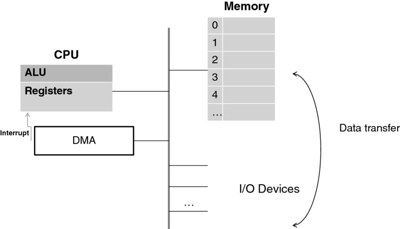
Figure 3.24 Direct Memory Access (DMA).
This is what DMA is needed for: a device (or, to be precise, a part of the device called a device controller) often needs to transfer a large stream of bytes to or from main memory. A disk and a network driver are good examples of devices with such needs. Had the CPU itself been involved in the task of dealing with these I/O streams, it would not have had sufficient time to do its main job—executing instructions. DMA is there to take on this task, and it works as follows. DMA has access to both the devices and the memory bus. As the computer clock ticks to drive the cycles in the machine operation, the DMA may “steal” some cycles periodically to perform the memory transfer on behalf of the CPU or, alternatively—especially in the case of a large transfer—the DMA may take the memory bus away from the CPU for the duration of the transfer. (In the latter case, the CPU would work with its own fast memory cache instead of the main memory, which gets updated later.) In a nutshell, the DMA is delegated the task of data transfer between the memory and the CPU, and in some architectures it is even used for intra-memory data transfer. When DMA is finished, it interrupts the CPU.
The DMA problem with I/O virtualization is that in the traditional architecture DMA writes to the “real” (i.e., not virtual) memory. If this approach were followed slavishly, directed I/O would give a virtual machine unprotected access to the physical memory, which is shared among several virtual machines. This would be a flagrant security violation. In fact, this would also violate the isolation principle, since software in one virtual machine could hurt all other virtual machines.
To deal with this problem, a type of MMU (appropriately called the I/O MMU—sometimes also spelled IOMMU) is employed, as depicted in Figure 3.25. Similarly to the MMU of Figure 3.11, where the MMU performs virtual-to-real memory translation for the CPU, the I/O MMU performs this function for DMA. With that, the memory space is partitioned among the devices, and the translation and partitioning caches are typically included with hardware, which often provides memory protection. (For an example, see [21] for a description of the Intel VT-D approach.)
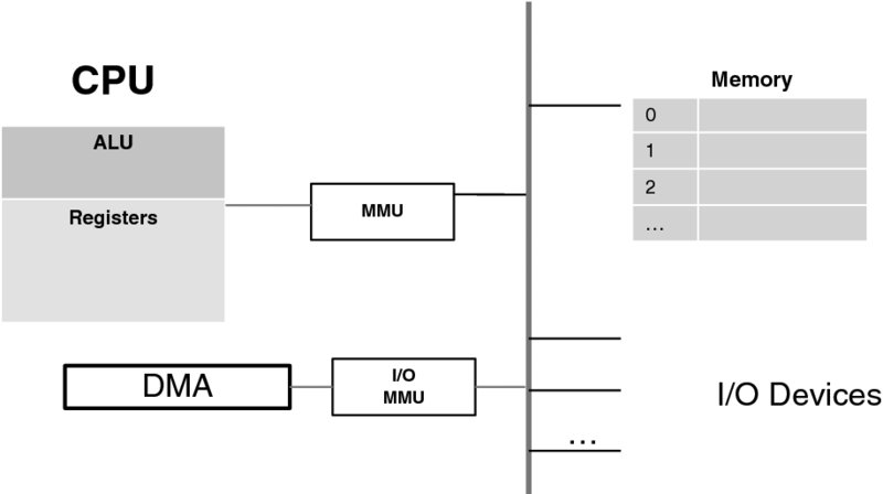
Figure 3.25 I/O MMU.
This approach supports virtual machine isolation and provides a degree of security. Yet, as [021] points out, the challenge here is posed by dynamic translation mappings. The issues are similar to general paging, and the overarching problem is the performance penalty resulting from the extra work that the hypervisor needs to perform. In fact, this work needs to be performed before DMA has finished a memory transfer, which brings yet another problem of the tolerable delay in DMA operations. The performance problems associated with employing I/O MMU have been analyzed in an earlier paper [24].
Directed I/O still remains an active research problem, as does the overall I/O virtualization subject. The well-known “Berkeley View of Cloud Computing” [25]—in its catalog of obstacles to Cloud deployment—lists17 “performance unpredictability.” The I/O virtualization hinges on sharing I/O devices, and it is the dependency that stubbornly remains problematic. (On the contrary, sharing main memory and CPU has proven to work well.) Fortunately, there are ideas for overcoming this problem, and the earlier success of IBM mainframes keeps one hopeful.
On this optimistic note, we finish our review of virtualization concepts and technologies. Now we can illustrate the implementation of these concepts and technologies with specific examples of popular hypervisors.
3.3.5 Hypervisor Examples
In this section we illustrate the concepts discussed so far using several examples of widely used hypervisors: Xen hypervisor, KVM hypervisor, as well as hypervisors developed by VMware and Oracle. We conclude the section with a description of the NOVA microhypervisor, which will provide a natural segue to the section on hypervisor security that follows.
We start with the Xen hypervisor, comprehensively described in [22]. (The open-source code for Xen is hosted at www.xen.org.) Xen is a Type-1 (“bare-metal”) hypervisor. It is operating-system agnostic, and it can, in fact, run concurrently guest VMs that use different operating systems.
As far as the virtualization taxonomy is concerned, Xen supports both paravirtualized and fully virtualized guests, respectively called PV and HVM. (The latter acronym stands for “Hardware-assisted Virtualization Mode.” Of course, HVM can be used only on processors that support full virtualization extensions—both Intel and AMD processor extensions are supported.)
For guests running in HVM, Xen emulates low-level hardware and firmware components—such as graphic, network, and BIOS adapters, using techniques described in the previous section. Predictably, emulation often results in degraded performance. Xen deals with this by creating yet another mode, called PV-on-HVM (or PVHVM), in which an HVM guest is paravirtualized only partly.
Xen's approach to handling physical I/O devices is straightforward and elegant. To explain it, we need to introduce, with the help of Figure 3.26, the Xen domain concept.

Figure 3.26 Virtual machine I/O support in Xen.
Xen creates a special environment—called a domain—for each guest. “Normal” guests (which amount to all but one specialized guest) each run in their own unauthorized domain, domU. One specialized domain, Domain 0 (or dom0), is reserved for a privileged guest—which probably should have been called a “virtualized host” because it is part of the control system that hosts all other virtual machines. To this end, Domain 0 is created at Xen boot time, and it is restricted to running specific operating systems (typically Linux, but other systems are also supported—with new ones added from time to time). Domain 0 is also the place where policies are specified. Separation of mechanisms and policies that control the use of the mechanisms is a Xen design principle. A Xen hypervisor executes the mechanisms according to the policy configured in dom0.
As far as the I/O is concerned, the trick is that all physical devices are attached only to the dom0 guest which handles them—with the unique privileges it has been assigned. That solves the problem of the I/O devices recognizing only one owner. All other guests understand that their machines have no I/O devices attached but that all such devices are on the machine where the dom0 guest resides. This is not a problem, because all the virtual machines are network-addressable and hence network I/O can be used.
Figure 3.27 illustrates the operation of I/O in Xen. When a guest in domU needs to communicate with a device, it uses the upper half of the split I/O driver.18
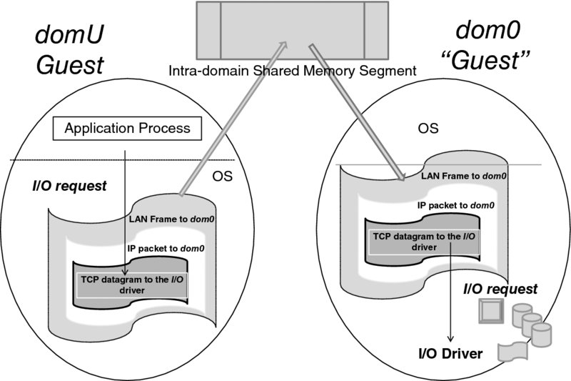
Figure 3.27 Xen network I/O optimization using shared memory.
The I/O request is sent via TCP to dom0 using the network module. In the process, a TCP datagram is constructed, which is enveloped into an IP packet. The IP packet is then encapsulated in a link-layer frame, which is supposed to be sent over the Local Area Network (LAN)—an act that would normally require a “real” I/O performed by the network driver. Instead of emulating a LAN literally, Xen deposits the frame into a common (to both domU and dom0) memory segment on the physical machine. (This is an act of optimization, which does introduce a security risk and therefore requires a careful protection scheme.)
Dom0 receives the frame on the “LAN,” peels off the link-, network-, and transport-layer packaging, and handles the I/O request to the actual I/O driver which handles the respective device. When the I/O is complete, dom0 sends it back through the network by reversing the above process. It should be noted that the actual operation is more complex than its rather simplistic rendition here, as it involves multiple exchanges in support of a TCP session, as specified by the TCP.
KVM (the acronym is sometimes spelled in small letters) exploits the new guest operating mode, mentioned earlier in this chapter. Like Xen, KVM is a Type-1 hypervisor;19 unlike Xen, KVM creates a virtual machine as a Linux process—running over the Linux kernel. Like Xen, KVM is an open-source project.20
KVM supports full native virtualization on the extended x86 CPUs (both Intel VT and AMD-V), as well as on other processors, the list of which continues to grow.21 In addition to the full native virtualization, KVM also supports paravirtualization for the Linux and Microsoft Windows operating system-based guests in the form of a paravirtualized network driver. With the help of the Quick EMUlator (QEMU),22 a patched version of KVM works with Mac OS X.
Again, with the KVM architecture [19], a virtual machine is created through the same interface as a regular Linux process. In fact, each virtual CPU appears to the administrator as a regular Linux process. This is largely a matter of the user interface though.
KVM provides device emulation using a modified version of QEMU, which emulates BIOS as well as extended bus extensions, disk controllers (including those of SCSI), network cards, and other hardware and firmware components.
Specifically, a virtual machine is created by opening a Linux device node (/dev/kvm). As a new process, the machine has its own memory, separate from that of the process that created it. In addition to creating a new virtual machine, /dev/kvm provides the controls for allocating memory to it, accessing the machine's CPU registers, and interrupting the CPU.
Using Linux's memory management capabilities, the kernel configures the guest address space from non-contiguous pages (as illustrated schematically in Figure 3.13). The user space can also be mapped into physical memory, which helps in emulating DMA.
KVM modifies Linux by introducing a new execution mode, guest mode, with the transition diagram depicted in Figure 3.28. (The two other modes supported by Linux, similar to the Unix operating system, are the kernel and user modes.)
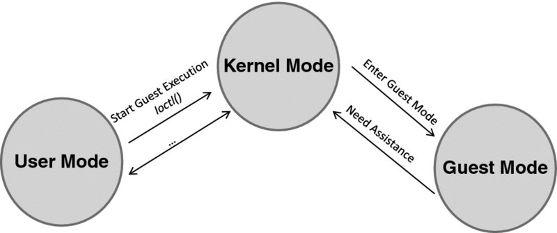
Figure 3.28 The state transition diagram for the KVM modes.
This works as follows. The user-level code issues a system call via the Linux ioctl( ) function, with the request to execute the guest code. In response, the kernel causes the execution of the guest code in the guest mode. This continues until an exit event (such as a request for an I/O instruction, or an interrupt, or a time-out) occurs. When the CPU exits guest mode, it returns to the kernel mode. The kernel processes the event, and depending on the result, either resumes the guest execution or returns to the user.
As [19] observes, tight integration into Linux helps both developers and end users of KVM to reclaim Linux's many capabilities (such as scheduling, process management, and assignment of virtual machines to specific CPUs).
We stated earlier that KVM is a Type-1 hypervisor, but there is a difference in opinion in the developers' community on that. Some people argue that since KVM is administered via a Linux interface, and, in fact, a virtual machine appears as a Linux process, it is a Type-2 hypervisor. Here the fine line is demarcated by the privilege ring in which the hypervisor runs, and it so happens that the Linux subsystem embodied by KVM has the highest privilege. (Needless to say it runs on bare metal, but so does any code—unless it is interpreted by software. The defining difference, in our opinion, is the privilege granted to the hypervisor code.)
But whereas the issue of KVM being a Type-1 hypervisor is questioned, there are pure Type-2 hypervisors: the VMware® Workstation and the Oracle VM VirtualBox®.23 (In contrast, the VMware ESX and ESXi hypervisors are Type 1.)
The paper [18] that we cited in the review of the x86 virtualization also provides a comprehensive description of the VMware Workstation hypervisor (the authors of [18] prefer to use the term VMM). Unlike Xen, the VMware Workstation handles the problem of non-trapping privileged instructions in near real time by scanning the binary image and replacing problematic instructions either with traps or with direct procedure calls to a library. (Remember that the difference here is that Xen, which employs paravirtualization, achieves a similar result by pre-processing the operating system code; VMware requires no such pre-processing—the code is changed on the fly after the image has been loaded.)
Another Type-2 hypervisor, Oracle VM VirtualBox (comprehensively described in its User Manual [26]) employs a combination of techniques that are different from both paravirtualization and full software emulation (although it uses the latter in special circumstances).
The VirtualBox software, through its ring-0 kernel driver, sets up the host system so that the guest code runs natively, with VirtualBox lurking “underneath” ready to assume control whenever needed. The user (ring-3) code is left unmodified, but VirtualBox reconfigures the guest so that its system (ring-0) code runs in ring 1. The authors of [26] call this “a dirty trick,” but there is nothing dirty about it since ring 1 on x86 has typically been left unused. When the system code (now running in ring 1) attempts to execute a privileged instruction, the VirtualBox hypervisor intercepts control. At that point, the instruction can be given to the host OS to execute or it can be run through the QEMU recompiler.
One interesting example mentioned in [26] when recompilation is invoked by VirtualBox—using its own disassembler24 to analyze the code—is “when guest code disables interrupts and VirtualBox cannot figure out when they will be switched back on.” All protected-mode code (such as BIOS code) is also recompiled.
It is important to note that all hypervisors mentioned so far support live migration. The problem here is non-trivial, as live migration involves copying the virtual machine memory while this memory can still be modified (the machine naturally needs to continue running on the old host until all the memory is copied), so it is a multi-pass process, in which careful synchronization between the old and new hosts is needed. Besides memory transfer, there are other aspects to live migration, to which we will return later in this book.
Meanwhile, new hypervisors such as NOVA [27] are being developed as a result of the research effort to address OS security by making the OS kernel as small and simple as possible. (Just to quantify this, the Xen hypervisor has about 150,000 lines of code,25 while the NOVA hypervisor has only 9000.26) (There is a table in [27], in which the code sizes of most hypervisors mentioned in this section are compared.)
Although NOVA does not prevent paravirtualization, the authors of [28] state: “We do not use paravirtualization in our system, because we neither want to depend on the availability of source code for the guest operating systems nor make the extra effort of porting operating systems to a paravirtualization interface.” Nor does NOVA use binary translation; it relies solely on hardware support for full virtualization.
NOVA represents the third generation of microkernel (or μ-kernel) systems—the operating systems that provide only the most basic capabilities to an application: memory and process management as well as interprocess communications. The idea behind this approach is that the rest of the operating system capabilities, including file system management, can be performed by an application itself trapping to the kernel when a sensitive action needs to be performed. Microkernels were initially developed in connection with LANs, but later security—which requires simplicity in software—has become the major driver.
The NOVA microhypervisor is to a hypervisor what a microkernel is to a kernel. It provides only basic mechanisms for virtualization, virtual machine separation, scheduling, communication, and management of platform resources. The rest is moved up. To this end, each virtual machine has its own associated virtual-machine monitor, which runs as an unprivileged user application on top of the microhypervisor. This architecture is depicted in Figure 3.29.
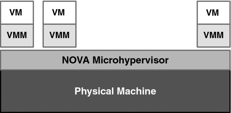
Figure 3.29 NOVA architecture (simplified).
Note that this architecture is drastically different from all others that we have reviewed so far in that the hypervisor is split into a monolithic microkernel part and the user part replicated for each virtual machine. What is essential here is that the microkernel is specifically designed with security in mind: the decomposition of the hypervisor minimizes the amount of privileged code.
This does not come without a cost, however, as the authors of [28] note: “By implementing virtualization at user level, we trade improved security … for a slight decrease in performance.”
This discussion leads us to the subject of the next (and last) section in this chapter.
3.3.6 Security
Security is by far the most complex matter in Cloud Computing. Cloud Computing combines multiple technologies, and so all the threats endemic to each of these technologies are combined, too. The matter is further complicated by the different security demands of different service and deployment models. This necessitates a three-pronged approach to security in Cloud Computing: (a) understanding the security threats and evaluating the risks—along with their respective mitigation mechanisms—brought in by each of the technologies involved (operating systems, virtualization, data networking at the routing and switching layers, web applications, to name just the major ones); (b) analyzing the risks and mechanisms in light of a specific service model and specific deployment model; and (c) developing the holistic security picture. We will address generic security mechanisms systematically in a separate chapter, while the technology-specific pieces belong in the chapters where the respective technologies are described. Thus, the present chapter deals only with virtualization security, which ultimately boils down to hypervisor security.
The motivation for paying attention to hypervisor security should be obvious now. A hypervisor is a single point of security failure; if it is compromised, so are all the virtual machines under its control. How can it get compromised? For example, just as a carefully constructed worm (discussed in Section 3.2.3) “escapes” a user process's code and takes over the computer resources that only an operating system may control, so can a malicious guest code in an attack that, in fact, is called an escape [27] break out of a virtual machine to take control of the hypervisor and, consequently, all other virtual machines on the same physical host.
Assuming for the moment that the host hardware has been fully protected against tampering and that the booting process is safe, the attacks can come in the form of maliciously modified operating system and device drivers that schedule DMA to write—in the absence of I/O MMU—into the “wrong” memory. The devil here is in the rather complex detail of the interface between a virtual machine and the host, which provides, in the words of [27], “the attack surface that can be leveraged by a malicious guest operating system to attack the virtualization layer.” If there is a vulnerability in the interface (and, as is well known, no complex software specification exists without having one), it can be exploited so that a virtual machine takes over the hypervisor—or rather executes at the same privilege level. (This is the reason why the NOVA architecture provides a dedicated VMM for each virtual machine, a feature that adds an extra layer of isolation. Even if a virtual machine takes over its VMM, which runs as an unprivileged application, there is still no damage to the top-level hypervisor.)
When the booting process is compromised (typically through manipulation of unprotected firmware), it is possible to install malicious programs that run with the highest privilege—“at the root” in Unix parlance, whence comes a common name for this type of program—a rootkit. The worst part of it is that typically, rootkits cannot even be detected.
A synopsis of the rootkit history is presented in [29]. Rootkits started as “Trojan horses”27 that ran at the user level without doing much more harm than just hiding themselves, but, with the appearance of administrative tools that had the ability to detect them, morphed into kernel-level malicious programs. Just when the intrusion-detecting tools followed them there, so new ways had to be found to avoid detection.
Rootkits—or rather non-malicious programs exhibiting rootkit-like stealth—have been used for seemingly legitimate purposes (enforcement of copyright protection being a notorious example), but this appears to be a gray area as far as laws are concerned. There is substantial academic research into rootkits, which aims at discovering the vulnerabilities the rootkits may exploit. The SubVirt project, described in [29], has been developed jointly by Microsoft and the University of Michigan. The Virtual Machine-Based Rootkit (VMBR) is one outcome of the project. VMBR inserts itself between the hypervisor and the target operating system by manipulating the system boot sequence. This can be achieved either through “a remote vulnerability” (unspecified in the paper) or social engineering (fooling the user, bribing the vendor, or corrupting “a bootable CD-ROM or DVD image present on a peer-to-peer network”). Once the root privileges are gained, VMBR is installed on the disk (which requires some massaging of the disk blocks and the data they already contain). At that point, the boot records are also cleverly modified—in a way that avoids actual detection of the modification. To achieve this, the boot blocks are manipulated “during the final stages of shutdown, after most processes and kernel subsystems have exited.” Both Microsoft Windows XP and Linux operating systems have been reported to be invaded in this way, with gory technical detail presented in [29]. As far as the hypervisors go, the proof-of-concept VMBR is reported to be implemented on Linux/VMware and Microsoft Windows/VirtualPC platforms.
Perhaps VMBR would have remained an obscure academic exercise, had it not been for a clear case of practicality which the researches made by also implementing a nice array of services (such as “a keystroke sniffer, a phishing web server, a tool that searches a user's file system for sensitive data, and a detection countermeasure which defeats a common VMM detection technique”). The researchers also demonstrated that their VMBR was effective in modifying an observable state of the system, which made it very hard to detect—so hard that “one of the authors accidentally used a machine which had been infected by our proof-of-concept VMBR without realizing that he was using a compromised system!”
A key point of the resulting defense strategy to detect these types of rootkit is to run detection software at a layer below VMBR so that it can “read physical memory or disk and look for signatures or anomalies that indicate the presence of a VMBR, such as a modified boot sequence.” Protection at this level can also be implemented in firmware. Prevention, using secure boot techniques, is also recommended and, in our opinion, it is the best course of action; however, if a safe boot medium (i.e., a shrink-wrapped CD-ROM) has already been poisoned through a social engineering scheme, that won't help.
While the SubVirt VMBR was implemented for the standard (non-virtualizable x86 CPU), another research project produced the Blue Pill VMBR, designed for the fully virtualizable AMD chip. (For detail and references, see Joanna Rutkowska's blog.28) The Blue Pill code has been freely distributed, but there has been significant controversy around the project, motivating many a company to block access to these pages on its corporate network.
So far, we have reviewed cases where malicious software either “took over” the hypervisor or otherwise was executed at the hypervisor level. It turns out that even taking control of a hypervisor per se may be unnecessary for inflicting damage; it may be sufficient instead to exploit vulnerabilities in virtual machine isolation.
An unobtrusive (passive) attack, in which an adversary learns what is supposed to be secret information, may inflict serious damage. To this end, it is important to learn and remember how much the information about the inner workings of a physical computer—even what looks like innocuous information—may reveal. There is a whole series of side-channel attacks in which hardware (e.g., CPU, memory, or devices) usage patterns can be used to reveal—with differing degrees of difficulty–various secrets, including cryptographic keys.
The very information on the specific physical host residence of a virtual machine must be kept secret. (As we learn later in the book, this is very similar to the long-standing practice by network and service providers of keeping the network infrastructure secret.) This explains why the authors of [30]29 caused a significant stir in the industry by reporting their experiments using a well-known service of a major Cloud provider, specific to the Xen hypervisor (and based on comparisons of dom0 IP addresses).
The researchers had demonstrated that it was “possible to map the internal Cloud infrastructure, identify where a particular target VM is likely to reside, and then instantiate new VMs until one is placed co-resident with the target.” Once instantiated, the machines mounted cross-VM side-channel attacks to learn (through CPU data caches) the CPU utilization measurements. Various attacks that can be mounted based on these data—including keystroke timing (in which the times between two successive keystrokes allow you to guess a typed password)—are also described in [30].
Among the recommended approaches to mitigating risk, the authors of [30] mention obfuscation of both the internal structure of Cloud providers' services and the placement policy. For example, providers might inhibit network-based co-residence checks. Another, somewhat vague, recommendation is to “employ blinding techniques to minimize the information that can be leaked.” The problem with that is that it is next to impossible to predict what type of information can be used as a side-channel. The best solution, in authors' opinion, is “simply to expose the risk and placement decisions directly to users.” With that, a user may require a dedicated physical machine and bear the costs. Unfortunately, this defies the principles of Cloud Computing. Side-channel attacks are considered somewhat far-fetched at the moment; however, the argument for the protection of the information on a Cloud provider's infrastructure is important, sound, and timely. Later in the book, we will address mechanisms for achieving that.
To conclude this chapter, we cite the NIST recommendations [27] pertinent to hypervisors:
- Install all updates to the hypervisor as they are released by the vendor. Most hypervisors have features that will check for updates automatically and install the updates when found. Centralized patch management solutions can also be used to administer updates.
- Restrict administrative access to the management interfaces of the hypervisor. Protect all management communication channels using a dedicated management network, or authenticate and encrypt the management network communications using FIPS 140-2 validated cryptographic modules.30
- Synchronize the virtualized infrastructure to a trusted authoritative time server.
- Disconnect unused physical hardware from the host system. For example, a removable disk drive might occasionally be used for backups or restores but it should be disconnected when not actively being used. Disconnect unused NICs31 from any network.
- Disable all hypervisor services such as clipboard or file sharing between the guest OS and the host OS unless they are needed. Each of these services can provide a possible attack vector. File sharing can also be an attack vector on systems where more than one guest OS share the same folder with the host OS.
- Consider using introspection capabilities32 to monitor the security of each guest OS. If a guest OS is compromised, its security controls may be disabled or reconfigured so as to suppress any signs of compromise. Having security services in the hypervisor permits security monitoring even when the guest OS is compromised.
- Consider using introspection capabilities to monitor the security of activities occurring among guest OSs. This is particularly important for communications which in a non-virtualized environment were carried over networks and monitored by network security controls (such as network firewalls, security appliances, and network Intrusion Detection and Prevention Solution (IDPS) sensors).
- Carefully monitor the hypervisor itself for signs of compromise. This includes using self-integrity monitoring capabilities that hypervisors may provide, as well as monitoring and analyzing hypervisor logs on an ongoing basis.
Incidentally, there is an argument in the industry that augmenting hypervisor with introspection services may provide additional attack vectors if only because of the increased size of code. Performance is often cited as a problem too.
An alternative is to develop a privileged appliance—a VM that provides introspection services through a hypervisor-exposed API. This takes care of the performance concerns (since the services are performed at the appliance's expense) as well as the hypervisor-code-creep concern. But exposing introspection API may be dangerous in its own way if the access to this API is not controlled to limit it only to the appliance.
Yet another approach to introspection, which works in a controlled environment (such as Private Cloud), is to avoid hypervisor altogether and instead install root-kit-like agents in each virtual machine. These agents monitor the VM behavior and log it.
The research on virtualization security is ongoing. A novel and promising approach, called NoHype, is being investigated at Princeton University [31, 32]. Here a hypervisor merely prepares the environment for a virtual machine to run and then assigns it to a specific CPU core, which would be “owned” by this machine. This approach can accommodate particularly sensitive situations where the highest level of VM isolation (short of using a standalone computer) is needed.
Notes
References
- Creasy, R.J. (1981) The origin of the VM/370 time-sharing system. IBM Journal of Research and Development, 25(5), 483–490.
- Tanenbaum, A.S. (2006) Structured Computer Organization, 5th edn. Pearson Prentice Hall, Upper Saddle River, NJ.
- Knuth, D. (1997) Art of Computer Programming, Volume 1: Fundamental Algorithms, 3rd edn. Addison-Wesley Professional, New York.
- Eichin, M.W. and Bochlis, J.A. (1989) With microscope and tweezers: An analysis of the Internet virus of November 1988. Proceedings of the 1989 IEEE Symposium on Security and Privacy, May 1–3, Cambridge, MA, pp. 326–343.
- Stravinsky, I. (1988) Petrushka, First Tableau (full score). Dover Publications, Mineola, NY, p. 43.
- Tanenbaum, A.S. (2007) Modern Operating Systems, 3rd edn. Prentice Hall, Englewood Cliffs, NJ.
- Silberschatz, A., Galvin, P.B., and Gagne, G. (2009) Operating System Concepts, 8th edn. John Wiley & Sons, New York.
- Bach, M.J. (1986) The Design of the Unix Operating System. Prentice Hall, Englewood Cliffs, NJ.
- Motorola (1992) Motorola M68000 Family Programmer's Reference Manual. Motorola, Schaumburg, IL.
- Organick, E.I. (1972) The Multics System: An Examination of Its Structure. MIT Press, Boston, MA.
- Graham, R.M. (1968) Protection in an information processing utility. Communications of the ACM, 11(5), 365–369.
- Kidder, T. (1981) The Soul of a New Machine. Atlantic, Little, Brown, Boston, MA.
- Goldberg, R.P. (1973) Architecture of Virtual Machines, 2nd edn. Proceedings of the AFIPS National Computer Conference, June 4–8, Montvale, NJ, pp. 74–112. http://flint.cs.yale.edu/cs428/doc/goldberg.pdf.
- Popek, G.J. and Goldberg, R.P. (1974) Formal requirements for virtualizable third generation architectures. Communications of the ACM, 17(7), 412–421.
- Robin, J.S. and Irvine, C.E. (2000) Analysis of the Intel Pentium's ability to support a secure Virtual Machine Monitor. Proceedings of the 9th USENIX Security Symposium, August 14–17, Denver, CO, pp. 129–144.
- Intel Corporation (2010) Intel® 64 and IA-32 Architectures, Software Developer's Manual, Volume 3A: System Programming Guide, Part 1. Order Number: 253668-034US, March.
- Advanced Micro-Devices (2012) AMD64 Technology. AMD64 Architecture Programmer's Manual, Volume 3: General-Purpose and System Instructions. Publication No. 24594 3.19. Release 3.19, September.
- Adams, K. and Agesen, O. (2006) A comparison of software and hardware techniques for x86 virtualization. ASPLOS-XII Proceedings of 12th International Conference on Architectural Support for Programming Languages and Operating Systems, New York, pp. 412–421.
- Kivity, A., Kamay, Y., Laor, D., et al. (2007) kvm: The Linux Virtual Machine Monitor. Proceedings of the Linux Symposium, June 27–30, Ottawa, Ont., pp. 225–230.
- Nakajima, J. and Mallick, A.K. (2007) Hybrid-virtualization—enhanced virtualization for Linux. Proceedings of the Linux Symposium, June 27–30, Ottawa, Ont., pp. 86–97.
- Intel (2006) Intel® virtualization technology for directed I/O. Intel® Technology Journal, 10(03). ISSN 1535-864x, August 10, 2006, Section 7.
- Chisnall, D. (2007) The Definitive Guide to the Xen Xypervisor. Prentice Hall Open Source Development Series, Pearson Education, Boston, MA.
- Waldspurger, C. and Rosenblum, M. (2012) I/O virtualization. Communications of the ACM, 55(1), 66–72.
- Ben-Yehuda, M., Xenidis, J., Ostrowski, M., et al. (2007) The price of safety: Evaluating IOMMU performance. Proceedings of the Linux Symposium, June 27–30, 2007, Ottawa, Ont., pp. 225–230.
- Armbrust, M., Fox, A., Griffith, R., et al. (2009) Above the Clouds: A Berkeley view of Cloud computing. Electrical Engineering and Computer Sciences Technical Report No. UCB/EECS-2009-2A, University of California at Berkeley, Berkeley, CA, February 10.
- Oracle Corporation (n.d.) Oracle VM VirtualBox® User Manual. www.virtualbox.org/manual/.
- Scarfone, K., Souppaya, M., and Hoffman, P. (2011) Guide to Security for Full Virtualization Technologies. Special Publication 800-125, National Institute of Standards and Technology, US Department of Commerce, January.
- Steinberg, U. and Kauer, B. (2010) NOVA: A microhypervisor-based secure virtualization architecture. Proceedings of the 5th European Conference on Computer Systems (EuroSys'10), Paris, pp. 209–222.
- King, S.T.; Chen, P.M., Wang, Y., et al. (2006). SubVirt: Implementing malware with virtual machines. Proceedings of the 2006 IEEE Symposium on Security and Privacy (S&P'06), Oakland, CA, pp. 327–341.
- Ristenpart, T., Tromer, E., Shacham, H., and Savage, S. (2009) Hey, you, get off of my Cloud: Exploring information leakage in third-party compute Clouds. Proceedings of CCS'09, November 9–13, 2009, Chicago, IL.
- Keller, E., Szefer, J., Rexford, J., and Lee, R.B. (2010) NoHype: Virtualized Cloud infrastructure without the virtualization. ACM SIGARCH Computer Architecture News, 38(3), 350–361.
- Szefer, J., Keller, E., Lee, R.B., and Rexford, J. (2011) Eliminating the hypervisor attack surface for a more secure Cloud. Proceedings of the 18th ACM Conference on Computer and Communications Security, ACM, pp. 401–412.