

Chapter 8
Personal Computer Components: Motherboards and Processors
CERTIFICATION OBJECTIVE
![]() 1101: 3.4 Given a scenario, install and configure motherboards, central processing units (CPUs), and add-on cards
1101: 3.4 Given a scenario, install and configure motherboards, central processing units (CPUs), and add-on cards
![]() Two-Minute Drill
Two-Minute Drill
Q&A Self Test
Together, this chapter and Chapters 9 and 10 introduce you to basic computer hardware concepts, including motherboards, CPUs, memory, adapters, storage devices, power supplies, display devices, and peripherals. These components comprise the basic set of hardware devices that you will work with over and over in your career as an A+ certified IT professional. This chapter begins the process by looking at the basic set of hand tools that a technician uses and by examining motherboards and CPUs—the components that empower and manage all the other components.
The hardware toolkit recommendations in this section include the tools outlined on CompTIA’s A+ Proposed Hardware and Software List, as well as some additional tools you should know about. We will revisit many of these tools in scenarios in coming chapters. Chapter 17 covers the network-specific tools recommended in CompTIA A+ 1101 exam Objective 2.8.
The Hardware Toolkit
As a new PC technician, you might begin with a repair toolkit that is not very extensive: perhaps a small assortment of screwdrivers and nut drivers, a small flashlight, and an assortment of spare screws and nuts. You’ll add tools as you need them for special jobs. You may decide to purchase a basic computer technician’s toolkit or assemble the components yourself. Figure 8-1 shows some of the most basic tools a computer technician uses on the job, and following that is a more complete list of components you might want in your kit, depending on your responsibilities. Note that this list doesn’t include network tools, which are covered at the beginning of Chapter 17.
FIGURE 8-1
An assortment of basic tools
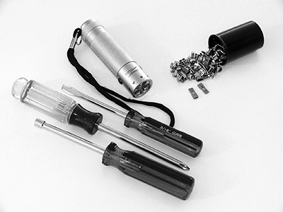
![]() Screwdrivers You should have an assortment of Phillips head, flathead, and Torx screwdrivers, as well as varying sizes of nut drivers. For working on laptops, a very small Phillips head screwdriver is the single most important tool in your set. Flathead screws are seldom used in modern computer equipment, but you may need to use a flathead blade to pry something open at some point.
Screwdrivers You should have an assortment of Phillips head, flathead, and Torx screwdrivers, as well as varying sizes of nut drivers. For working on laptops, a very small Phillips head screwdriver is the single most important tool in your set. Flathead screws are seldom used in modern computer equipment, but you may need to use a flathead blade to pry something open at some point.
![]() ESD protection An ESD wrist strap helps prevent damage from static electricity when working on any component except the power supply, monitor, and laser printers. We discussed ESD wrist straps in Chapter 1. An ESD mat provides a static charge with a path to ground and is designed for the desktop or floor of a workspace. While this mat may not fit in your toolkit, it is something that should be available at any PC technician’s workbench.
ESD protection An ESD wrist strap helps prevent damage from static electricity when working on any component except the power supply, monitor, and laser printers. We discussed ESD wrist straps in Chapter 1. An ESD mat provides a static charge with a path to ground and is designed for the desktop or floor of a workspace. While this mat may not fit in your toolkit, it is something that should be available at any PC technician’s workbench.
![]() FRUs Field-replaceable units (FRUs) should be included in your hardware toolkit. An FRU is any component that you can install into a system onsite. This includes such items as memory modules, heat sinks, motherboard batteries, various adapter cards, hard drives, optical drives, keyboards, mice, fans, AC adapters, spare cables and connectors, power supplies, and even spare motherboards. Of course, all of this depends on the scope of your job and how cost-effective it is to have these items on hand. If you support hundreds of computers that are all the same make and model, it may make sense to have spare parts; if you support a diverse fleet of devices, probably not.
FRUs Field-replaceable units (FRUs) should be included in your hardware toolkit. An FRU is any component that you can install into a system onsite. This includes such items as memory modules, heat sinks, motherboard batteries, various adapter cards, hard drives, optical drives, keyboards, mice, fans, AC adapters, spare cables and connectors, power supplies, and even spare motherboards. Of course, all of this depends on the scope of your job and how cost-effective it is to have these items on hand. If you support hundreds of computers that are all the same make and model, it may make sense to have spare parts; if you support a diverse fleet of devices, probably not.
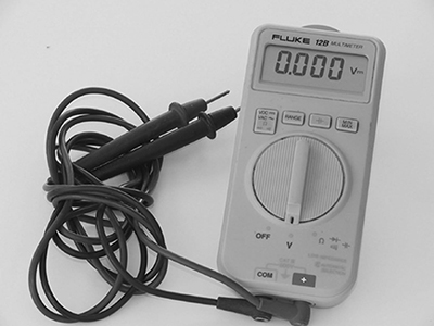
![]() Multimeter A multimeter is indispensable in determining power problems from a power outlet or from the power supply. You’ll use this handheld device to measure the resistance, voltage, and/or current in computer components (see Figure 8-2) using two probes (one negative, one positive) that you touch to power wires in the equipment you are testing. Multimeters can also be used for cable continuity testing, as described in Chapter 17.
Multimeter A multimeter is indispensable in determining power problems from a power outlet or from the power supply. You’ll use this handheld device to measure the resistance, voltage, and/or current in computer components (see Figure 8-2) using two probes (one negative, one positive) that you touch to power wires in the equipment you are testing. Multimeters can also be used for cable continuity testing, as described in Chapter 17.
FIGURE 8-2
A simple multimeter
![]() Power supply tester A power supply tester is a specialized device for testing a power supply unit and is a bit safer to use than a multimeter for this purpose. A power supply tester comes with connectors compatible with the output connectors on a standard power supply, rather than with just the simple probes of a multimeter. An LCD display or LEDs show the test results.
Power supply tester A power supply tester is a specialized device for testing a power supply unit and is a bit safer to use than a multimeter for this purpose. A power supply tester comes with connectors compatible with the output connectors on a standard power supply, rather than with just the simple probes of a multimeter. An LCD display or LEDs show the test results.
![]() Camera A digital camera or smartphone will enable you to document the condition of a computer before you begin troubleshooting. One important way we use a camera is to document the cabling and connections—both external and internal—before making any changes so that we can reconnect all components correctly. A camera is also handy for capturing low-level error messages that cannot be captured with a software screen capture utility and for capturing the model and serial number on a device.
Camera A digital camera or smartphone will enable you to document the condition of a computer before you begin troubleshooting. One important way we use a camera is to document the cabling and connections—both external and internal—before making any changes so that we can reconnect all components correctly. A camera is also handy for capturing low-level error messages that cannot be captured with a software screen capture utility and for capturing the model and serial number on a device.
![]() Thermal paste Thermal paste is an electrically insulating, heat-conductive paste that helps increase the transfer of heat between a hot chip and a heat-dissipating fan or heat sink. It is also called thermal grease or heat sink compound. You apply it in a thin layer between the components. Depending on the type, it may or not have adhesive properties; usually when it aids in adhesion, it is called thermal adhesive. When it comes in a solid pad that you place between the heat sink and the chip, it’s called a thermal pad.
Thermal paste Thermal paste is an electrically insulating, heat-conductive paste that helps increase the transfer of heat between a hot chip and a heat-dissipating fan or heat sink. It is also called thermal grease or heat sink compound. You apply it in a thin layer between the components. Depending on the type, it may or not have adhesive properties; usually when it aids in adhesion, it is called thermal adhesive. When it comes in a solid pad that you place between the heat sink and the chip, it’s called a thermal pad.
![]() Drive adapter A SATA to USB connector enables you to use an internal hard drive (using a serial ATA connector) as an external hard drive (using a Universal Serial Bus connector). It may be called a drive enclosure if it contains a plastic shell into which you can mount the drive to make it easier to handle and transport.
Drive adapter A SATA to USB connector enables you to use an internal hard drive (using a serial ATA connector) as an external hard drive (using a Universal Serial Bus connector). It may be called a drive enclosure if it contains a plastic shell into which you can mount the drive to make it easier to handle and transport.
EXERCISE 8-1
What’s in Your Toolkit?
In this exercise you will explore the tools used by PC technicians.
![]() If you are already working as a technician, gather your tools and compare them to the previously mentioned list. What would you add to the printed list? What is in the list that you would like to add to your toolkit?
If you are already working as a technician, gather your tools and compare them to the previously mentioned list. What would you add to the printed list? What is in the list that you would like to add to your toolkit?
![]() If you are not a technician, find one who will talk to you about the tools of the trade. You may find this person at work, at school, or even at a local PC repair business. Ask the technician to tell you which tools they use the most and what they recommend you have in a basic toolkit.
If you are not a technician, find one who will talk to you about the tools of the trade. You may find this person at work, at school, or even at a local PC repair business. Ask the technician to tell you which tools they use the most and what they recommend you have in a basic toolkit.
CERTIFICATION OBJECTIVE
![]() 1101: 3.4 Given a scenario, install and configure motherboards, central processing units (CPUs), and add-on cards
1101: 3.4 Given a scenario, install and configure motherboards, central processing units (CPUs), and add-on cards
The motherboard is the real estate on which a PC is built; all PC components are directly or indirectly connected to this large printed circuit board (PCB). The rest of this chapter introduces many of the topics of CompTIA A+ 1101 exam Objective 3.4, including motherboard sizes (ATX and ITX), motherboard connector types, motherboard and CPU compatibility, CPU architecture, expansion cards, and cooling.
Motherboard Form Factors and Components
Each internal and external PC component connects, directly or indirectly, to a single circuit board. The motherboard, also referred to as the mainboard, the system board, or the planar board, is made of fiberglass, typically brown or green, and with a meshwork of copper lines, called traces. Power, data, and control signals travel to all connected components through these pathways. A group of these wires assigned to a set of functions is collectively called a bus.

Safety first! Hands-on experience is important for preparing for your CompTIA A+ exams, and as you study you will want to install and remove components on a PC system. Make sure you understand safety procedures, as detailed in Chapter 1.
In this section, we focus on types of motherboards, their typical integrated components, and the differences between the motherboard’s communication busses and what components can connect to a motherboard through these various busses. Most of the specifications discussed in this section pertain more to desktop PCs than to laptops, but we will point out some differences where applicable. We will also address laptop hardware in more detail in Chapter 14.
If you work with experienced PC technicians, read trade publications, or visit technical websites, you’ll probably see the slang term mobo used in place of motherboard.
Sizes/Form Factors
A motherboard form factor defines the type and location of components on the motherboard, the power supply that will work with it, the size of the motherboard, and the corresponding PC case that will accommodate both. There are several motherboard form factors, each with different layouts, components, and specifications. A motherboard will use only certain CPUs and types of memory. Therefore, if you decide to build a computer from components, you must ensure that the motherboard, power supply, CPU, memory, and case will all work together.
A motherboard’s form factor does not tell you what CPUs and memory it is compatible with; there is little to no relationship there.

CompTIA A+ 1101 exam Objective 3.4 mentions two form factors: ATX and ITX. Be sure to pay attention to the differences between these form factors and know about their smaller-size variants. We discuss these form factors, as well as others that have some relevance to the exams, even if they are not listed in the objectives.
ATX
The Advanced Technology eXtended (ATX) motherboard standard was released by Intel Corporation in 1996 and has been updated many times over the years—both officially and through proprietary variations by manufacturers. Counting all the variations, it is the most commonly used form in PCs. The original ATX motherboard measures approximately 12" wide by 9.6" from front to back (305 mm × 244 mm).
Figure 8-3 shows an ATX motherboard in an older desktop.
FIGURE 8-3
An ATX motherboard installed in a case with the CPU and some cables visible
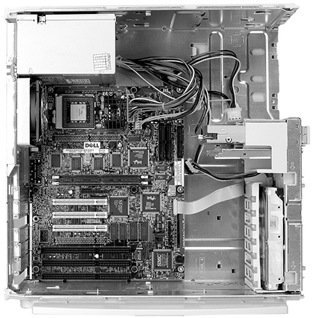
Depending on the manufacturer and the intended market, today’s ATX motherboard will contain memory slots for the latest RAM types and support for firmware-controlled power management, multimedia, Intel or AMD CPU sockets, disk drive connectors, and USB.
Besides the original full-size ATX motherboard, there are three smaller sizes: Micro-ATX, Flex-ATX, and Mini-ATX. Table 8-1 provides their dimensions.
TABLE 8-1
Motherboard Approximate Size Comparison
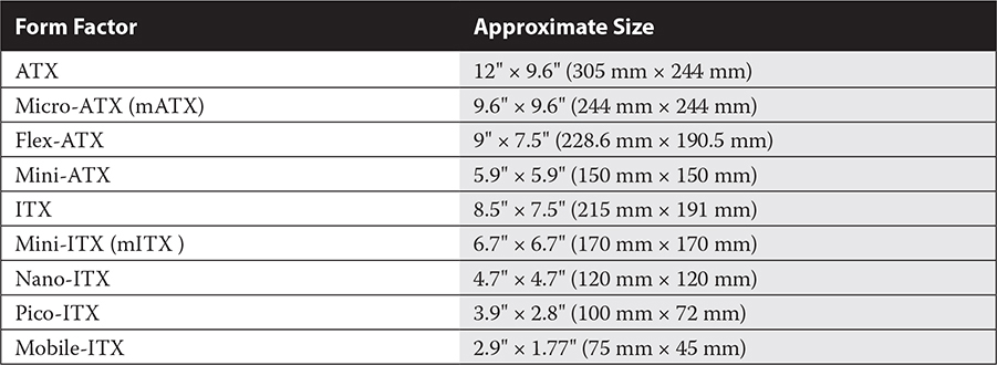
Knowing the dimensions of the various motherboard sizes is useful if you are trying to determine what size a particular board is (so you can order a replacement, for example).
ITX
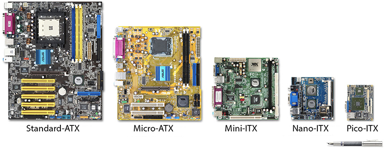
ITX, originally named EPIA, was developed by chipset-company VIA in 2001 for use in low-power CPUs (such as very small desktop PCs designed to be part of home entertainment systems) and chipsets in low-cost PCs but was never used in production. Subsequent designs—the Mini-ITX, Nano-ITX, Pico-ITX, and Mobile-ITX—have been progressively smaller and targeted to embedded systems. See Table 8-1 for their specifications. The only one listed in the current CompTIA A+ 1101 exam objectives is the original ITX.
You would think that something named micro would be smaller than something named mini but that’s not always the case. For example, Mini-ATX is smaller than Micro-ATX, as you can see in Table 8-1. Notice that the “m” in mATX stands for micro, whereas the “m” in mITX stands for mini. Figure 8-4 compares the various form factors of ATX and ITX visually.
FIGURE 8-4
A comparison of ATX and ITX sizes (Credit: VIA Gallery from Hsintien, Taiwan, CC BY 2.0 https://creativecommons.org/licenses/by/2.0, via Wikimedia Commons)
EXERCISE 8-2
Comparing Motherboards
In this exercise you will compare motherboard specifications and examine the motherboard on a desktop PC.
1. From a computer with an Internet connection, use your browser to search on the ATX and ITX form factors and their smaller variations.
2. Notice the locations of the CPU, expansion bus, and memory slots.
3. If possible, open a desktop PC, following the safety guidelines outlined in Chapter 1, and determine the form factor of the motherboard by measuring its dimensions and comparing them to those in Table 8-1. Do not disconnect or remove any components within the case.
4. Keep the computer open while you complete this chapter, locating as many of the components described as you can.
5. When you are finished, close the computer case, reconnect the computer, and make sure that it works as well as it did before you opened it.
Motherboard Components
The components built into a motherboard include sockets for various PC components, including the CPU and memory; expansion slots (such as PCIe and M.2); built-in components such as network, display, and sound adapters; hard drive controllers; support for various port types (such as USB); and the chipset. Following is an explanation of all of these, with the exception of hard drive controllers, which we will describe in Chapter 9 during the discussion of storage types.
RAM Slots
A motherboard has slots, or sockets, for system memory. Depending on the vintage and the manufacturer of a motherboard, special sockets accept one of the various types of RAM chips attached to small circuit boards called memory modules or, less formally, memory sticks. There have been many different types over the years, but the ones you need to know today are all some type of Dual Inline Memory Module (DIMM). Different DIMMs include double data rate 3 (DDR3), DDR4, and DDR5 and small outline DIMM (SODIMM) versions of all of those. You’ll learn about these in Chapter 9.
Some motherboards have paired RAM slots in a configuration called dual-channel architecture in order to improve RAM performance. In such motherboards, DIMMs must be installed in matched pairs in the slots with matching colors. For example, there might be two blue slots and two black ones. Dual-channel is a function of the motherboard, not the RAM itself; ordinary RAM is used in dual-channel slots. There are also triple-channel and quad-channel architectures. More about that in Chapter 9.
How do you find out what memory modules will work on a specific motherboard? You read the motherboard user guide. If you cannot find one for your computer, find the manufacturer’s name and the model of the motherboard (or computer system) and query your favorite Internet search engine. You will often find the right manual in PDF format.
Bus Architecture
The term bus refers to pathways that power, data, or control signals use to travel from one component to another in the computer. Standards determine how the various bus designs use the wires. There are many types of busses on the motherboard, including the memory bus used by the processor to access memory. In addition, each PC has an expansion bus of one or more types. The most common types of expansion bus architectures are PCI, PCIe, and Mini PCIe, and we discuss these next. The following bus types are those that you can expect to see in PCs today.
The terms bus, system bus, and expansion bus are interchangeable. A bus refers to either a system bus or an expansion bus attached to the CPU.
PCI Peripheral Component Interconnect (PCI) is an expansion bus architecture released in 1993 but still around on some motherboards today for backward compatibility. In some documentation it is called conventional PCI to distinguish it from the more modern PCIe.
The PCI bus transfers data in parallel over a 32-bit or 64-bit data bus. (The 32-bit type is much more common.) Over the years several variants of the PCI standard were developed, and data transfer speeds vary depending on the variant and the bus width. The original 32-bit PCI bus ran at 33.33 MHz (megahertz) with a transfer rate of up to 133 megabytes per second (MBps).
PCI slots are 3" long and are typically white. PCI cards and slots are not compatible with those of other bus architectures. PCI was the assumed slot type for almost all expansion boards for various functions for many years, and motherboards typically had a lot of them. PCI was originally developed for video, back in the days when PCI was the fastest bus around, but few video cards are PCI anymore because there are faster alternatives. Nowadays a typical motherboard will have only one PCI slot, with the rest of them being PCIe.
PCIe Peripheral Component Interconnect Express (PCIe) differs from PCI in that it uses serial communications rather than parallel communications, as well as different bus connectors. Also called PCI Express and PCI-E, it has replaced PCI on modern systems and is incompatible with conventional PCI adapter cards.
Although PCIe programming is similar to PCI, the newer standard is not a true bus that transfers data in parallel, but rather a group of serial channels. The PCIe connector’s naming scheme describes the number of serial channels each handles, with the designations x1, x4, and x16 indicating 1, 4, and 16 channels, respectively.
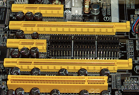
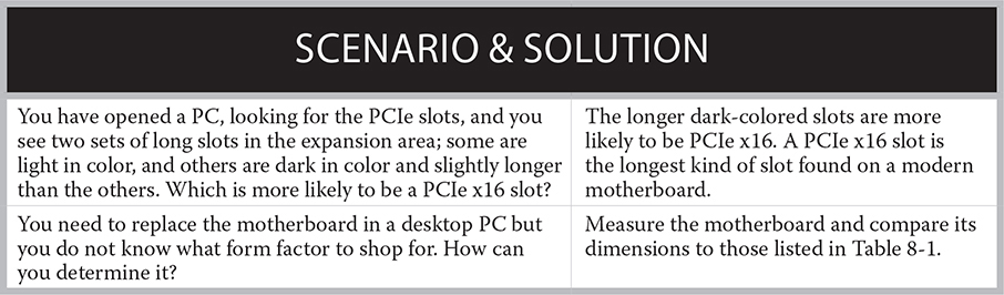
On the motherboard, a PCIe x1 connector is approximately 1½" long, whereas PCIe x4 is about 2" long, and PCIe x16 is close to 4" long. Figure 8-5 shows several PCIe slots and one conventional PCI slot.
FIGURE 8-5
From top to bottom: PCIe x4, x16, x1, and x16 and conventional PCI (Photo: https://commons.wikimedia.org/wiki/File:PCIExpress.jpg [Creative Commons license])
The PCIe transfer rate depends on which version of the standard the bus installation supports. For instance, PCIe 1.0 supports data transfers at 250 MBps per channel, with a maximum of 16 channels. Therefore, the maximum transfer rate for 16-channel PCIe 1.0 is 4 GBps. PCIe 2.0, released in late 2007, added a signaling mode that doubled the rate to 500 MBps per channel. This rate was redoubled to 1 GBps per channel with the PCIe 3.0 (PCIe Gen 3) standard, which supports a signaling mode of 1 GBps per channel but is downward compatible with existing PCIe products. PCIe 4.0 (PCIe Gen 4) doubles it again, and PCIe 5.0 (PCIe Gen 5) doubles that.
For the CompTIA A+ exam, you don’t need to know the full specifications of standards such as PCI and PCIe, but you should understand the basics of each standard. For instance, know that PCI and PCIe are both expansion bus interfaces; remember that PCIe is the newer of the standards and is serial, whereas PCI is parallel. Be sure you can identify their physical differences on a motherboard.
Mini PCI and Mini PCI Express Mini PCI has a 32-bit data bus, like conventional PCI. The biggest difference is that Mini PCI is much smaller than PCI—both the card and the slot. If a laptop has an installed Mini PCI slot, it is usually accessible via a small removable panel on the bottom of the case. Mini PCI cards also come in three form factors: Type I, Type II, and Type III. Types I and II each have 100 pins in a stacking connector, whereas Type III cards have 124 pins on an edge connector.
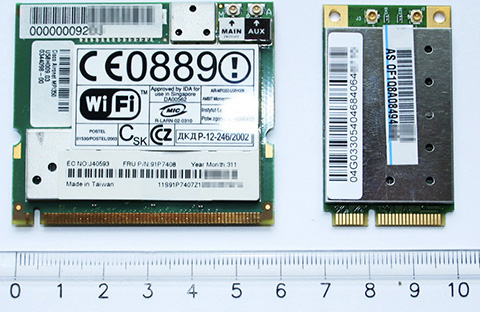
Mini PCIe has replaced Mini PCI in modern laptops. (Depending on the manufacturer, this is also called PCI Express Mini Card, Mini PCI Express, Mini PCIe, or simply MiniCard.) This specification provides much faster throughput with a 64-bit data bus. At 30 mm × 26.8 mm, it is much smaller than a Mini PCI card and has a 52-pin edge connector. Figure 8-6 compares a Mini PCI card to a Mini PCI Express card.
FIGURE 8-6
Comparison of Mini PCI (left) and Mini PCI Express (right)
Although Mini PCI Express is more modern than PCI Express, it is still on the wane, thanks to a newer technology known as M.2, discussed next.
M.2
M.2 (pronounced M dot 2) is a modern connector type for mounting solid-state expansion cards and solid-state drives on a motherboard. It has replaced mSATA, an earlier way of mounting solid-state storage on a motherboard using the PCI Express Mini Card layout and connectors. We’ll revisit M.2 in Chapter 9, when we talk about storage interfaces, but since M.2 is a multipurpose slot type, it warrants mention here as well.
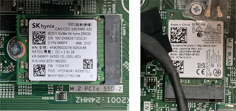
M.2 can use the PCI Express (x4) bus, Serial ATA, and/or USB internally, depending on the M.2 module. Different types of M.2 connectors are keyed differently to ensure compatibility. On a motherboard, the M.2 slots will be labeled so you’ll know which ones to use for each device. Figure 8-7 shows two different M.2 slots: one for an SSD (also called M-key) and one for a wireless network adapter (also called E-key). Notice the writing adjacent to the slots; the SSD one says PCIe SSD-2, and the Wi-Fi one says M.2 WLAN.
FIGURE 8-7
An SSD (left) and a Wi-Fi card (right) in two different kinds of M.2 slots
There are multiple key IDs (A through M), each with certain pins notched on the connector. You don’t need to know the specs on these different keys; just know that different keying exists and that you have to match the M.2 device with the right slot. If you’re interested in the detailed specs on the different socket variants, there are plenty of Internet resources on it.
Motherboard Power Connectors
If you carefully examine a motherboard, you will see many connectors that range from tiny 3-pin connectors to long 24-pin connectors. These range from power connectors to connectors for onboard components, such as audio, I/O interfaces, and more. These will normally be labeled and well documented in the motherboard user’s manual.
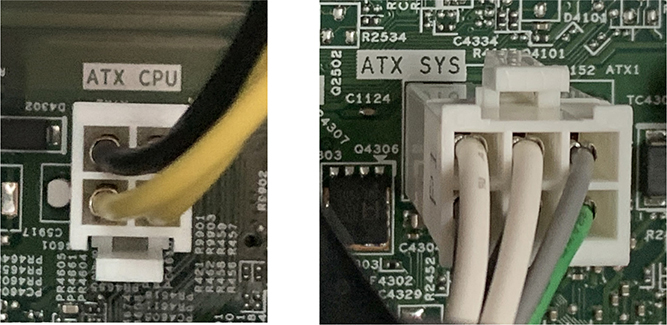
The main power connector for a modern desktop PC motherboard is a 24-pin connector with many different wire colors. In addition, look for one or more 4-pin or 6-pin connectors to the motherboard. The 4-pin variety is also called P4 or ATX 12V and delivers extra 12-volt power. This is necessary on many newer systems because they require more 12-volt power than the few 12-volt (yellow) wires in the 24-pin power supply connector can deliver. The 6-pin type is an auxiliary connector (AUX or ATX SYS), which supplies extra 3.3V and 5V current to the motherboard. You can distinguish it because it may have red, white, black, gray, and/or green wires but no yellow ones. Yellow is for 12V. Figure 8-8 shows one of each.
FIGURE 8-8
A four-pin ATX 12V connector (left) and a six-pin AUX connector (right)
Older motherboards may have a 20-pin power connector. Some power supplies have a 24-pin connector where the last 4 pins snap off the end so the connector can be used on a 20-pin motherboard. This is called a 20+4 connector. Going the other direction, you can buy a 20-pin to 24-pin adapter that allows an older (20-pin) power supply to plug into a newer (24-pin) motherboard.
There may also be an additional 6-pin or 8-pin power connector on the power supply, called a PCIe power connector, designed to give PCIe cards a power boost. These are 12V connectors and will have yellow and black wires only. On some high-end (that is, power-hungry) systems you may see an 8-pin connector labeled EPS12V. (It is sometimes called EATX12V or ATX12V 2×4.) As the “12” in the name implies, it provides even more 12V power to the motherboard. Chapter 10 covers power supplies and power connectors in more detail.
Laptop motherboards have different power connections than described here, but we aren’t as concerned with them because of the way that power is supplied to a laptop. The connections are simpler, less configurable, and often proprietary. With a desktop, you can go out and buy a standardized power supply box to install in a desktop PC case. With a laptop, the power connectors and the motherboard’s relationship to the incoming power vary among brands and models, and the technician does not normally need to make a lot of different power connections by hand.
Headers
Modern ATX motherboards have most of their ports built directly into the side of the board, so they are externally accessible via the back of the PC without having to run any cables between the motherboards and the ports. However, they don’t always have every port built in directly; sometimes you may need to run a cable from a header to a port. That’s particularly true when you need to connect to something on the front of the PC case. Another header that’s difficult to overlook (because it’s so large) is the main connector from the power supply to the motherboard, the P1.
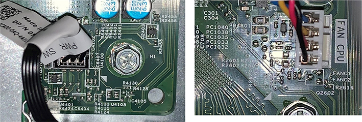
A header is a set of pins on the motherboard to which you can connect a cable. A common kind of port to have a header on a motherboard is USB, but you may also see headers for other port types, depending on the motherboard design. Most motherboards have headers for connecting the power button and the CPU fan, as shown in Figure 8-9. Pay close attention to the labels near the ports, and do not get them confused. Consult the motherboard manual if the writing on the motherboard is unclear. Some headers have little plastic frames around them to protect the pins from getting bent; that’s common with headers for connecting older parallel ATA (PATA) drives, as you will learn in Chapter 9, and also with headers for connecting USB 2.0 and 3.0 cables.
FIGURE 8-9
Headers for a power button (left) and a CPU fan (right)
USB 2.0 and USB 3.0 have separate kinds of headers; the USB 2.0 type is (usually) 9-pin, and the USB 3.0 type is 20-pin.
Firmware and Chipsets
Firmware refers to software instructions, usually stored on read-only memory (ROM) chips—special memory chips that retain their contents when the computer is powered off. Most PC components, such as video adapters, hard drives, network adapters, and printers, contain firmware. Firmware built into the motherboard controls the basic functions, capabilities, and configurability of a computer system. Firmware on the motherboard includes the chipset and system BIOS. You will learn how to configure a motherboard’s firmware later in this chapter.
A critical component of the motherboard firmware is the chipset. When technicians talk about the chipset, they are usually referring to one or more chips designed to control and manage the data movement within the motherboard. It is the chipset that determines which CPUs and memory the motherboard will accept and how fast the various busses move data. Choosing a motherboard appropriate to the system you are building involves understanding the motherboard chipset’s capabilities.
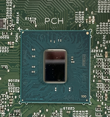
In past eras, it was common for a motherboard’s chipset to be composed of two chips: the northbridge and the southbridge. Today, however, single-chip chipsets are common, such as the Platform Controller Hub (PCH) chip on some Intel motherboards, as shown in Figure 8-10. On some motherboards you might not be able to readily identify the chipset chip(s) because one or more may be covered with a heat sink and/or a fan.
FIGURE 8-10
A PCH chip on an Intel motherboard
CPUs and Their Sockets
A personal computer is more than the sum of its parts. However, the most important part, without which it is not a computer, or even a useful tool, is the central processing unit (CPU), also called the processor. But a CPU may not be the only processor in a PC. Other components may include a processor for performing the intense work of the component. The most common example of this is the graphics processing unit (GPU) found on modern video adapters, used to render the graphics images for the display. GPUs were integrated onto system boards along with the video adapter, and now there is a trend of integrating the GPU into some CPUs. Wherever it is located, the GPU saves the CPU for other system-wide functions and improves system performance. The following is an overview of CPUs, their purposes and characteristics, manufacturers and models, technologies, and the motherboard sockets into which they fit.
In a PC, the CPU is the primary control device for the entire computer system. The CPU is simply a chip containing a set of components that manages all the activities and does much of the “heavy lifting” in a computer system. The CPU interfaces with, or connects to, all of the components such as memory, storage, and input/output (I/O) through busses. The CPU performs a number of individual or discrete functions that must work in harmony in order for the system to function. Additionally, the CPU is responsible for managing the activities of the entire system.
A CPU is printed in a single operation onto a silicon wafer, not assembled from discrete parts. Nevertheless, inside each CPU is a variety of component parts, each with a specific function. These include the control unit, the arithmetic logic unit (ALU), registers, busses, and memory caches. Each of these is explained in an upcoming section.
The Machine Cycle
The CPU’s internal components perform four basic operations that are collectively known as a machine cycle. The machine cycle includes fetching an instruction, decoding the instruction, executing the instruction, and storing the result. Figure 8-11 provides an overview of this process. Understanding this process up-front will make the discussions of the individual components more relevant.
FIGURE 8-11
The four-step machine cycle employs the control unit, ALU, and registers.
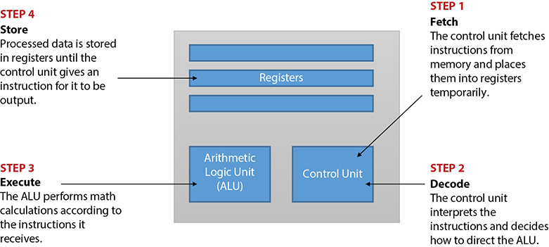
Control Unit
The control unit is the “traffic cop” inside the CPU. It uses electrical signals to direct the CPU’s overall operation. It signals to other parts of the computer system what they should do. The control unit interprets instructions and initiates the action needed to carry them out. First it fetches, which means it retrieves an instruction or data from memory. Then it decodes, which means it interprets or translates the instruction into strings of binary digits that the computer understands.
The machine cycle isn’t covered on the CompTIA A+ 1101 or 1102 exam, but understanding it can make it easier to grasp some other concepts that are covered, such as multiple cores, multithreading, and number of bits of processing.
ALU
The arithmetic logic unit (ALU) is the part of the CPU that executes the instructions (Step 3 in Figure 8-11). It performs arithmetic operations on the data (add, subtract, multiply, and divide) and performs logical operations such as comparing two data strings and determining whether they are the same.
Registers
A register is a memory location inside the CPU, providing temporary storage that can be used as a scratch pad for calculations. Two types of registers are used in modern systems: dedicated registers and general-purpose registers. Dedicated registers are usually for specific functions such as maintaining status or system-controlled counting operations. General-purpose registers are for multiple purposes, typically when mathematical and comparison operations occur. Placing data into a register is the storing step of the machine cycle (Step 4 in Figure 8-11).
Busses
Busses, generically speaking, are pathways over which data travels. External busses, such as the front-side bus, carry data to and from the CPU, and internal busses in the CPU itself move data between its internal components.
Cache Memory
Because the CPU is so much faster than the computer’s other components, it can potentially spend a lot of time idle, waiting for data to be delivered or picked up. The farther the data has to travel to get to the CPU, the longer the delay. To help minimize these delays, modern CPUs have multiple caches. A cache (pronounced “cash”) is a pool of extremely fast memory that’s stored close to the CPU and connected to it by a very fast pathway. Only when the needed data isn’t found in any of the caches does the system have to fetch data from storage (for example, the main memory of the PC, or a hard drive).
When the CPU needs some data, it looks first in the L1 (level 1) cache, which is the one closest to the CPU. The L1 cache is an on die cache; that means when the CPU is stamped into the silicon wafer, the L1 cache is stamped into the same piece of silicon at the same time.
The L1 cache is quite small, so it can’t hold everything the CPU has recently used or may need to use soon. If the data needed isn’t found in the L1 cache, the system looks in the L2 cache. On older systems, the L2 cache was on the motherboard, but on modern systems, it’s in the CPU package next to the silicon chip. If the data isn’t in the L2 cache, the system checks the L3 cache, which is larger and slightly farther away from the CPU, although still within the ceramic chip that we call the CPU. On a multicore CPU (discussed later in this chapter), all of the cores share a common L3 cache.
CPU Technologies and Characteristics
A number of technologies are employed in a CPU, based on both standards and proprietary designs, which are constantly changing. This section describes common CPU technologies and characteristics you should know for the exam.
x64 and x86 Architecture
A CPU supports a certain word size, which is the size of the chunk of data that can enter and exit the CPU in one operation. This is also called the chip’s architecture, and on modern PC CPUs it is either 32-bit (called x86) or 64-bit (called x64). The architecture is significant because it determines what version of the operating system the PC can use. On a 32-bit CPU, you are limited to the 32-bit version of Windows, which supports a maximum of 4 GB of RAM. A 64-bit CPU can handle either 64-bit or 32-bit Windows.
Remember that x64-based systems can access more than 4 GB of RAM. Also know that in a 64-bit version of Windows, 64-bit programs are stored in the C:Program Files folder and 32-bit programs are stored in the C:Program Files (x86) folder.
Advanced RISC Machine
Look back at Figure 8-11 and recall the machine cycle. The control unit fetches instructions and uses them to perform calculations. But what are these instructions? They are built-in functions that the CPU understands, like the functions in Excel and other spreadsheet programs. Some CPUs have a lot of instructions they can understand; these are called Complex Instruction Set Computers (CISCs).
The advantage of a complex instruction set is that the CPU can perform a wide variety of tasks efficiently. To further explore the spreadsheet metaphor, think about how a spreadsheet program contains hundreds of functions for doing math calculations. If you didn’t have a function for something you wanted to do (for example, averaging a group of numbers), you would have to write out the math formula to do it, and that would be a much longer and more complicated programming instruction. Today’s desktop and laptop CPUs are mostly CISC.
If you had a CPU that needed to do a smaller set of tasks but it needed to do them extremely quickly, one way to achieve that would be to reduce the instruction set and focus all the CPU’s power on performing just a few functions. That’s the idea behind a Reduced Instruction Set Computer (RISC).
Advanced RISC Machine (ARM) is one of the most common types of RISC CPUs. RISC CPUs are found in most mobile devices today, such as Android and Apple tablets and smartphones, and in gaming consoles. ARM’s efficient architecture helps battery-powered devices last longer between charges. They are also found in some special-purpose computers that are dedicated to a narrow set of activities. In past decades they were also used on some low-cost desktop and laptop PCs, such as Chromebooks, and at the high end on some servers and supercomputers.
There is a special version of Windows called Windows on ARM that runs on some RISC CPUs designed for desktops and laptops. There are some limitations as to the apps that will run, but generally most Microsoft Store (aka Universal Windows Platform, or UWP) apps will run, as well as most 32-bit Windows apps. There are also some compatibility differences between Windows 10 and Windows 11 on ARM devices.
Clock Speed
The clock speed of a CPU is the speed at which it can potentially execute instructions. CPU clock speed is measured in billions of cycles per second, or gigahertz (GHz). A CPU of a certain type and model may be available in a range of clock speeds.
All other features being equal, the CPU with the faster clock speed will be more expensive. However, when comparing different models of CPUs, the faster clock speed alone will not determine the fastest CPU. Manufacturers use many technologies to speed up CPUs. For example, the number of clock cycles required for completing the same operation can vary among CPU models. To the end user, the perceived speed of a PC, or lack of it, may involve other aspects of the computer’s total design, such as the cache size, the amount and speed of the RAM, the speed of the busses, and the speed of the hard drive.
Multithreading
A thread, or thread of execution, is a portion of a program that can run separately from other portions of the program. A thread can also run concurrently with other threads. Multithreading, also known as hyperthreading or simultaneous multithreading (SMT), is a CPU technology that allows two or more threads to execute at the same time within a single execution core. This is considered partially parallel execution. Intel introduced hyperthreading in the Pentium 4 Xeon CPU, referring to it as Hyper-Threading Technology (HT Technology). Multithreading is the more preferred term today and the one listed in Objective 3.4 on the 1101 exam.
Multicore
The most visible change in CPUs in recent years has been the introduction of multicore CPUs with more than one core on the same integrated circuit. Each core is essentially a CPU with its own set of control unit, ALU, and registers. The first of these were dual-core CPUs containing two CPU cores. Quad-core CPUs are commonly available, and manufacturers offer 6-core and more—even 128-core Superchip CPUs.
Server computers have long been available with multiple CPUs, so why not simply install two or more single-core CPUs on the same motherboard? Two cores on the same chip can communicate and cooperate much faster than two single-core processors sharing a motherboard can. A dual-core CPU can simultaneously process two threads in true parallel execution, and each core has its own L1 cache; triple-core CPUs can simultaneously process three threads, quad-core four threads, and so on. On top of the advantage of using multiple cores, the manufacturers have made other changes to the CPU architecture to make them faster and more energy efficient.
Virtualization Support
Remember in Chapter 7 when we talked about hardware-assisted virtualization (HAV) and its usefulness on machines that run VM hypervisors? Another name for HAV is virtualization support. Most modern CPUs include virtualization support—the ability to manage multiple operating systems running at once through virtual machines—enabled through BIOS/UEFI settings. In Intel CPUs, the name of the group of technologies involved is Virtualization Technology (VT), which may have an additional symbol or letter associated with a particular CPU model. AMD’s virtualization technology is AMD-V. You used to have to consider HAV when shopping for a CPU, but today almost any new CPU is going to come with it.
Make sure you understand how CPUs differ from one another in areas such as x64/x86, CISC vs. ARM, number of cores, multithreading, and virtualization support.
CPU and Motherboard Brand and Model Compatibility
There are many CPU manufacturers, but the prevailing ones in the PC market today are Intel Corporation and Advanced Micro Devices, Inc. (AMD). Both companies manufacture more than CPUs, but their competition in the CPU market gets more attention in the trade and business press since AMD emerged as Intel’s major competitor.
Fortunately, you don’t have to memorize any names and characteristics of specific CPUs for the current CompTIA A+ exam. What is important for a tech to understand is that Intel and AMD are the two main players in the CPU market. A motherboard will support only AMD or only Intel—never both. Further, a motherboard will usually support only a very narrow band of specific models of CPUs from that one manufacturer, with a similar set of features. Each manufacturer makes dozens of CPU types and subtypes for nearly every type of device, from server to desktop to mobile hardware. There are multisocket motherboards for servers that accept multiple CPUs for increased processing power, CPU chips designed to be permanently mounted on mobile device motherboards (to save weight and space), and everything in between.
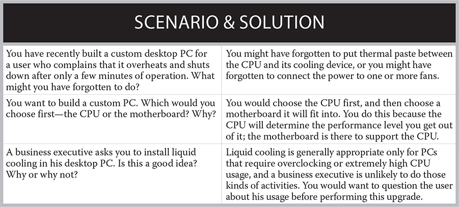
Cooling Mechanisms
The more powerful PCs become, the more heat they generate within the case. Heat is your PC’s enemy, and it should be yours, too. An overheated CPU will fail. Rather than allow heat to cause damage, several techniques—both passive and active—are used to maintain an optimum operating temperature. Some components will even slow down so they produce less heat before any damage occurs. Manufacturers have struggled to keep ahead of the heat curve and provide sufficient cooling for the entire system. These methods involve fans, heat sinks, thermal compounds, and even liquid cooling systems.
CPU and Case Fans
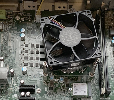
Early PCs relied on the design of the PC case and the power supply fan to provide all the cooling for the computer’s interior. During this era, the typical PC had vents in the front through which the power supply fan pulled cool air and in the back through which the heated air was exhausted. Today, we usually employ additional methods, but the power supply fan still plays an important part in cooling the PC. It is very common to see a fan mounted directly over the CPU, as shown in Figure 8-12.
FIGURE 8-12
An open PC with the CPU fan visible
One or more case fans may also supplement a power supply fan. A case fan is a fan mounted directly on the case, as opposed to a power supply fan, which is inside the power supply. Systems that do not come with a case fan may have mounting brackets for adding one or more case fans.
Heat Sinks and Fanless/Passive Cooling
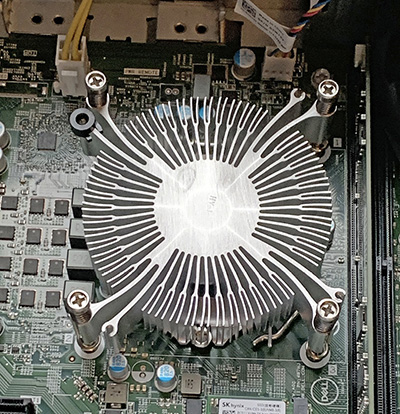
Another device that works to cool hot components is a heat sink. This is usually a passive metal object with a flat surface attached to a component—a chip, for instance. The exposed side of a heat sink has an array of fins used to dissipate the heat. The heat sink shown in Figure 8-13 was made visible by removing the fan shown in Figure 8-12. This combination of heat sink and fan can be very effective; the heat sink absorbs the heat from the CPU and then the fan blows the heat away. In other systems the heat sink and fan are a single unit.
FIGURE 8-13
A heat sink attached to a CPU
Early CPUs used standard heat sinks for cooling, and they worked well enough for those CPUs because those CPUs didn’t run very hot. On systems made in the last two decades, though, standard fanless (passive) heat sinks haven’t cut it; powerful fans have been required to pull the heat away effectively. Motherboards still employ passive heat sinks for other chips besides the CPU, like the main chipset chips or the GPU, but not the CPU itself.
However, new generations of fanless cooling devices released lately have been challenging the assumption that a fan is always required for the CPU. These vary in their construction, but generally include copper heat pipes and a large stack of nickel-plated aluminum fins.
Thermal Compounds
As you learned earlier in the chapter, thermal paste is an electrically insulating, heat-conductive paste that helps increase the transfer of heat between a hot chip and a heat-dissipating fan or heat sink. It is also called thermal grease, thermal pad, or heat sink compound. You apply it in a thin layer between the components. Depending on the type, it may or may not have adhesive properties; usually when it aids in adhesion, it is called thermal adhesive.
Liquid Cooling Systems
Many of today’s motherboards for sale on the Internet or at large electronics stores feature one or more liquid cooling systems, which range from sealed liquid cooling systems that transfer heat by conduction from several components to active systems that use tiny refrigeration units. Liquid cooling is generally more effective than standard cooling, so it is sometimes employed in overclocked systems (that is, systems that are rigged to run at higher clock speeds than the CPUs are rated for) to help keep the CPU cool enough to function at the higher speed. But it is also more expensive, is more difficult to install, and can cause serious system damage with short-circuiting in the event of a leak.
Be sure you are familiar with the differences in cooling methods, including fans/heat sinks vs. liquid cooling, and know how to apply thermal paste/pads.
Case Design
The design of each case allows for maximum airflow over the components. Part of this design is the placement of vents, positioned to either bring in fresh air or to exhaust air. If this airflow is disturbed, even by additional openings, the system may overheat. Therefore, be sure that all the expansion slot openings on the back of the PC are covered. The expansion card’s bracket covers each opening that lines up with an occupied expansion slot. A metal slot cover covers an empty slot in order to preserve the correct airflow.
EXERCISE 8-3
Checking Out Your Cooling System
If you have access to a PC with the conventional case-fan cooling system, check it out now.
1. Without opening the computer case, look for vents in the case.
2. If the computer is running, and if it is of a conventional design, you should hear a fan running in the power supply and see the vent from the power supply. You may hear another fan running and see a set of vents for that fan.
3. Are there vents that do not appear to have a case fan behind them?
4. Hold your hand by the vents you located and determine if airflow is going into or out of the computer case. Is the power supply fan blowing in or out? If you located a case fan, is it blowing in or out?
5. Make note of your findings and discuss with your classmates or coworkers.
Configuring a Motherboard
After you physically install a motherboard and attach components to it, the next step is to configure the motherboard to perform optimally with the installed hardware. On very old motherboards, a few key settings are configured using jumpers. On modern motherboards, however, nearly all setup is done through a firmware (BIOS or UEFI) setup utility.
Understanding BIOS and UEFI
Each computing device has a chip on its main circuit board with some basic firmware that helps the device start up and communicate with the operating system and the other hardware. This firmware is traditionally known as the basic input/output system (BIOS). A PC’s BIOS resides on the motherboard and is called the system BIOS. Each expansion card also has its own BIOS chip that, among other things, reports the device’s plug and play settings to the motherboard’s BIOS and to the OS.
The system BIOS is responsible for performing the power-on self-test (POST), a hardware test during startup, and informing the processor of the devices present and how to communicate with them. Whenever the processor makes a request of a component, the BIOS steps in and translates the request into instructions that the component can understand. That was true for many years and is true today, up to the point when an operating system loads, whereupon drivers loaded by the OS take over most of the BIOS functions.
The traditional PC system BIOS is a 16-bit program that requires x86-compliant hardware. However, newer systems that have large hard drives (more than 2.2 terabytes) bump up against a limitation there. Enter Unified Extensible Firmware Interface (UEFI), which has taken the place of a traditional BIOS on most motherboards.
In simplistic terms, UEFI is a 32-bit or 64-bit BIOS alternative that adds some features and benefits. From an end-user and PC technician point of view, it’s roughly equivalent to a BIOS. (A UEFI setup program is very similar to a BIOS setup program, for example.) The main advantages of UEFI are that it supports file systems that enable booting to large drives (2.2 terabytes and up), it supports 32-bit or 64-bit booting, and it’s not dependent on x86 firmware. Many technicians use the term BIOS (or CMOS; see the next section) to refer to both BIOS and UEFI firmware.
A Brief History of the PC System BIOS
BIOS was originally stored on a ROM chip that was completely inaccessible for user changes. To get a BIOS update, you had to replace the BIOS chip on the motherboard. As you can imagine, that was a hardship, especially because back in those days, there was no plug and play. If your BIOS didn’t recognize a certain type of drive or other hardware, you couldn’t use it.
As a workaround, systems began offering BIOS written on erasable programmable ROM (EPROM) chips. These BIOS chips had a little clear window in the top. You could put the chip in a special machine that would flash a strong light into that window that erased the BIOS chip. Then the machine would reprogram the chip. That’s how the name flash BIOS or flash ROM originated.
But even that was a pain. End users didn’t have the needed machine, and many small repair shops didn’t either. So the next evolutionary step was to make a BIOS chip that could be erased with a strong pulse of electricity, rather than light. This was known as electrically erasable programmable ROM (EEPROM). An EEPROM update could be done in place on the motherboard using a software utility. Big improvement!
The problem with EPROM and EEPROM chips was that, except when using their special update procedures, you couldn’t write changes to them. That meant that each time the PC turned on, it was a blank slate. The PC couldn’t remember what drives or memory were installed, what user settings were desired, or even the current date and time. To get around this, motherboards had another chip, a complementary metal-oxide semiconductor (CMOS). This was a special kind of dynamic RAM (DRAM) chip that stored the exceptions to the BIOS settings. First the BIOS would load its basic settings, and then the CMOS chip would load the changes to the defaults. The CMOS chip required electricity to hold its data, but it was a very small amount of electricity. Motherboard manufacturers supplied that electricity with a small battery on the motherboard.
As technology advanced, electrically rewriteable ROM chips became faster and less expensive, to the point where device makers were using them as a substitute for magnetic disk storage in systems. (USB flash drives and solid-state drives are two examples.) Motherboard makers began using this type of memory to hold the user customizations to the BIOS settings, rather than CMOS chips. Such chips don’t require the motherboard’s battery to retain their settings. So technically in modern motherboards there is no longer a CMOS chip. Motherboards still have a battery, but now it’s just to maintain the real-time clock (RTC), which remembers the date and time when the PC is shut off.
The utility used to write the user changes to the chip was known as CMOS setup or BIOS setup, depending on the BIOS brand and model. Even though you won’t find a CMOS chip on a motherboard anymore today, the term CMOS setup is still very common, referring to the firmware setup program. Sometimes a BIOS setup utility is even titled CMOS Setup in its interface.
Updating the Firmware
Motherboard manufacturers and PC makers periodically release firmware updates for their motherboards. These updates may correct bugs in the code and may add extra features, like support for a new type of device. Most PCs function just fine with the original firmware version they came with, but occasionally a problem can crop up that can be solved by updating the firmware to the latest version.
Updating the firmware involves running a program to “flash” the BIOS or UEFI. In modern terms, what that really means is to update the programming on the memory chip on the motherboard that holds the firmware. There’s not really any flashing going on anymore, although the name persists. You can download a firmware update and accompanying utility for installing it (perhaps in a single executable) from the website of the motherboard or PC manufacturer.
It is very important to follow the directions given by the manufacturer when updating the firmware. A botched update can render the system inoperable and require a replacement chip from the manufacturer.
Configuring the Firmware
The most common way to optimize a motherboard is to modify the BIOS or UEFI setup configuration program, also called the BIOS setup or CMOS setup. Literally hundreds of settings are available in different computers; this section looks mainly at the ones that are specifically mentioned in Objective 3.4 of the CompTIA A+ 1101 exam. The choices available, and the methods for selecting them, may vary from one manufacturer to another. The best reference for using the firmware setup menus is the motherboard manual.
Accessing Firmware Settings
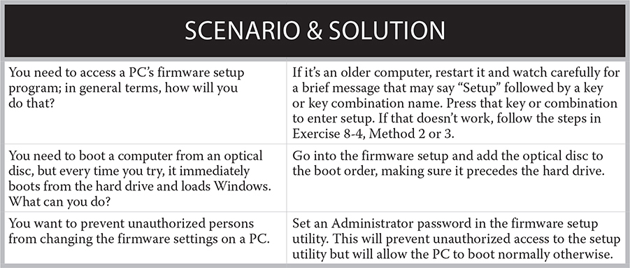
To access the computer’s firmware settings, closely watch the computer screen at startup. Following the system hardware test, you may see a message indicating the proper key sequence you should use to enter the firmware setup program. It may simply say “Setup” followed by a key or key sequence name. This key or key combination varies among computers but is typically F2, DELETE, or CTRL-ALT-ESC. In most systems, the message will appear for only three to five seconds, and you must use the indicated key combination within that allotted time.
On newer systems, you probably won’t see that prompt, though, and you’ll need to go another route. On PCs with Windows 8 and higher and UEFI, if the Secure Boot feature is enabled in the firmware settings, you will not see a prompt as the PC starts telling you to press a key to enter setup. On such systems, there is an alternative method of getting into the setup program through the Settings app. See Exercise 8-4 for details.
EXERCISE 8-4
Booting into Firmware Setup
This exercise provides three different methods of entering firmware setup. Choose the method that is appropriate for the system you are working with.
Method 1: For BIOS-Based Motherboards Use this method if you see a message about a key to press at startup. Systems that provide this are typically older ones running Windows 7 or earlier and/or have a BIOS rather than UEFI firmware.
1. Reboot your PC, and as it reboots, watch the screen for a message telling you what key to press to enter Setup.
2. When you see that message, press the key as quickly as you can. If you see the Windows splash screen, you missed the window of opportunity; allow Windows to finish loading, and then restart and try again.
Method 2: For Windows 10 Use this method if you are running Windows 10 and don’t see any message about a key to press at startup.
1. Click Start | Settings.
2. In the Settings app, click Update And Security. Then in the navigation bar, click Recovery.
3. Under the Advanced Startup heading, click Restart Now. Then at the Choose An Option screen, click Troubleshoot, and then click Advanced Options.
4. At the Advanced Options screen, click UEFI Firmware Settings and then click Restart. The PC reboots and opens the setup application.
Method 3: For Windows 11
Use this method if you are running Windows 11 and don’t see any message about a key to press at startup.
1. Right-click the Start button and choose Settings.
2. In the Settings app, click System | Recovery.
3. In the Advanced Startup section, click Restart Now. Then at the Choose An Option screen, click Troubleshoot, and then click Advanced Options.
4. At the Advanced Options screen, click UEFI Firmware Settings and then click Restart. The PC reboots and opens the setup application.
Navigating in the Firmware Setup Program
Firmware setup programs differ widely. Some allow you to use the mouse, and some only the keyboard. The names of the settings might also vary slightly. Use the program’s Help feature or on-screen prompts for information about how to navigate through the program and save or discard your changes. Usually, though, pressing the ESC key quits without saving, and pressing the F10 key quits and saves. The RIGHT and LEFT ARROW keys usually move between screens, the UP and DOWN ARROW keys move the highlight to select a different option, and pressing ENTER usually selects whatever option is highlighted.
EXERCISE 8-5
Viewing the Firmware Settings
In this exercise you will explore the firmware setup utility for a motherboard.
1. Enter the firmware setup program by completing Exercise 8-4.
2. Look at the bottom of the screen for navigation instructions, as well as how to access the Help utility (normally the F1 key). If it’s a mouse-enabled program, there might not be navigation keys.
3. Browse through the screens carefully, and if you have a digital camera handy, take a picture of each screen. On a mouse-enabled system, there may be a navigation bar or a list of screens.
4. Locate the settings described in the following sections.
5. When you have finished, use the indicated key combination to exit without saving any changes.
Backing Up Firmware Settings
Make notes about the current firmware settings before you change them in case you need to change them back. A quick way is to use a digital camera, taking a picture of each screen or capturing a video that shows you paging through the screens without making any changes. Also, look for a firmware-settings backup utility in the firmware setup menus, sometimes located on a Tools menu, or check out the firmware manufacturer’s website for backup instructions. Alternatively, look for a third-party firmware backup program.
Hardware Information
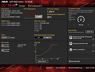
Usually the first screen you see is an informational one showing the system’s hardware configuration. If you are ever in doubt about the system hardware, this screen provides a good reference point. Figure 8-14 shows an example.
FIGURE 8-14
A UEFI BIOS utility’s main screen showing basic hardware information
Security Settings
Depending on the firmware make and version, you might have the option to configure up to three passwords in the Security section of firmware setup: Supervisor/Admin, User/System, and Hard Disk Drive (HDD). All are disabled by default.
Except in special high-security situations, we don’t recommend using the firmware-level passwords. It’s too easy to forget that they’re set when you pass along a PC to a new owner or to forget a password in times of distress, like when you need to get into the firmware setup to correct a problem in the middle of a tight deadline project.
The User or System password restricts booting the PC. A Supervisor or Admin password restricts access to the firmware-settings program itself or to change user passwords. Most firmware setup programs require that you first set a Supervisor/Admin password before it allows you to set a User/System password. Some systems also have an HDD password, which must be entered before a user can access the hard drive.
Some systems also have an option that allows you to enable the firmware interface to connect to a for-pay antitheft service. Enabling this option involves signing up for the service over the Internet and downloading additional software. Once you have enabled and subscribed to the service and connected the computer to the Internet, the software installed in your OS will contact the service’s servers and check for a theft report, as well as transmit the system and GPS tracking information concerning the location of the computer. This service may have a product name attached to it, such as Computrace or LoJack.
Even formatting or replacing the existing hard drive will not bypass this security because it takes advantage of the built-in Trusted Platform Module (TPM), an embedded security chip that stores encrypted passwords, keys, and digital certificates. Various services can use the TPM chip. Even without a for-pay location service, when you combine the use of TPM with a firmware-level Administrator password and a User password required at power-on, the computer is virtually useless to a thief. In firmware setup, there may be a TPM On option, as well as options for controlling specific TPM settings. The TPM On option lets you control whether TPM is visible to the operating system; it does not change any TPM settings. There may also be a general Enable/Disable option for TPM that does turn TPM on/off completely.
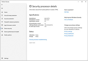
CompTIA A+ 1101 exam Objective 3.4 mentions encryption (separately from BIOS/UEFI settings), and under that, calls out TPM and Hardware Security Module (HSM). TPM and HSM are similar but not the same. TPM provides some basic encryption key storage services related to controlling access at the hardware level. You can view TPM information in Windows Pro and Enterprise editions, as shown in Figure 8-15. HSM is a more advanced technology that’s an add-on to systems that need extra security, providing hardware-accelerated cryptography along with key storage.
FIGURE 8-15
TPM settings in Windows Pro
Considering how often users forget passwords, using the combination of TPM, Administrator password, and a required User password at power-on may make a computer useless to its authorized user! Use these security measures only where and when required, such as protecting mobile computers that contain sensitive information. See “Resetting the BIOS/UEFI” later in this chapter for help with a forgotten firmware password.
The Secure Boot feature is enabled/disabled in firmware setup, but also relies on the PC having Windows 8 or later and UEFI. Provided all three of those pieces are present, Secure Boot helps prevent malware (such as a rootkit replacing the Windows boot loader) and unauthorized OSs from loading during the system boot process. Secure Boot is enabled by default on systems where it is available. One drawback of it is that you can no longer press a key at startup to enter firmware; you have to go in through Windows, as in Exercise 8-4. The Secure Boot feature may be controlled from the Security section or the Boot section in firmware setup, depending on the firmware brand and version.
One way that a hacker might try to introduce malware into a system is by inserting a USB flash drive. Some firmware setup programs enable you to disable the USB ports on the system. This would normally not be a great idea, because you lose access to the ports, but for a highly secure system, it could be useful. If you ever needed to use a USB port, you would need to re-enter the setup program (presumably you would have an Admin password protecting access to it) and re-enable the port(s). There might be separate options governing whether the USB ports can be used at all and whether they can be booted from.
Another security issue involving USB ports is related to Intel Active Management Technology (AMT). AMT is a tool that enables system admins to remotely manage systems outside of Windows. In 2017 a remote exploit was discovered that allowed hackers to use AMT to bypass a system’s password. If a system has an Enable USB Provision feature in the firmware setup, it should be enabled only if the managing organization requires it for USB-based AMT management.
Boot Sequence
Your system firmware will no doubt have a setting for selecting the order in which the system will search devices for an OS. You can normally select from among a variety of possible boot devices, including C: or hard disk, USB flash drive, and even the network. In the last case, the firmware will boot via your network interface card (NIC). All modern network cards support the ability to start a computer over the network, without relying on a disk-based OS, using an Intel standard called Preboot eXecution Environment (PXE).
If you plan to install a new OS on a system using a bootable external drive, you will need to go into the firmware setup program and change the boot order so that the optical drive precedes the hard drive. With this turned on, every time the system restarts with a bootable disc in the optical drive, you briefly see a message to press any key to boot from the external source. After installing a new OS, you might change the boot order back to start from the hard drive first. Then it only searches other drives at startup if it does not find an OS on the hard drive.
Fan Control
Many firmware setup programs provide a way of controlling the built-in fans in the system depending on your preferences. For example, you might choose cooler performance (more fan noise) or quieter performance (less cooling, but less fan noise). You might also be able to set the fan speed to Auto, allowing the firmware to choose a fan speed based on the internal temperature of the system. (Obviously that works only on systems with internal temperature sensors.)
Resetting the BIOS/UEFI
Older motherboards and other circuit boards sometimes have jumpers used to configure, enable, or disable a feature. A jumper is a small connector that slides down on a pair of pins jutting up from a circuit board, creating a connection between the two pins that changes the electrical flow through the motherboard, triggering a certain setting. Each possible jumper configuration is interpreted by the system firmware as a setting. Check the user manual that came with the motherboard or other circuit board to discover how to configure the settings you desire.
The one jumper remaining on nearly every modern motherboard is the one that resets the BIOS/UEFI in the event that you mangle its settings so badly that you can’t boot into its setup program anymore, or you assign a firmware password and then forget it. To reset the BIOS/UEFI setup, consult the motherboard manual to locate the reset jumper and learn what position resets the motherboard. Move the jumper to that position and start the PC to perform the reset. The motherboard manual will explain the amount of time to wait. Then return the jumper to its original position and reboot. Another way to reset is to remove the motherboard’s battery.
There might also be a setting in firmware setup that enables you to specify BIOS/UEFI recovery options. (You would need to do this ahead of time, when the system is working well.) For example, you might be able to set the firmware to permit BIOS/UEFI recovery from the hard drive, or automatic BIOS/UEFI recovery. You might also be able to tell the firmware to perform a firmware integrity check at every boot. There might also be a BIOS/UEFI Downgrade feature that enables you to go back to an earlier firmware version (for example, if a recent upgrade introduced a problem).
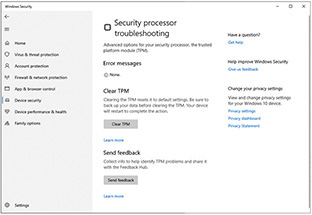
You can also clear TPM data from within Windows Pro or Enterprise, as shown in Figure 8-16.
FIGURE 8-16
Clearing TPM data from Windows
Motherboard Driver Software
Modern motherboards include a great many more devices and capabilities than older motherboards—often more than can be adequately supported by the motherboard firmware. In addition, some of the motherboard’s features work differently when accessed via different operating systems or require drivers specific to an OS. Therefore, when you purchase a motherboard, it will often come with a driver disc containing utilities or support files to install in specific operating systems. If it’s a retail-purchased PC (that is, if you didn’t buy the motherboard as a separate item), you should be able to download motherboard driver software from the company’s website. You will learn about installing and configuring motherboards and using a motherboard’s driver setup utilities in Chapter 11.
CERTIFICATION SUMMARY
Common computer components include the processor, memory, storage devices, and input and output devices. All of these devices have specific functions, and your familiarity with them will help you to determine when to upgrade or replace a component.
This chapter described general characteristics of motherboards, installed motherboard components and form factors, and CPU technologies. You must use a motherboard that supports the selected CPU and RAM. Motherboards have many integrated functions. This chapter introduced several of the technologies that CompTIA A+ 1101 exam may test you on. A good knowledge of these concepts is also important when you are repairing or upgrading a computer system. Chapters 9 and 10 will continue with explanations of other important PC components, and Chapter 11 will describe how to install and upgrade PC components.
 TWO-MINUTE DRILL
Here are some of the key points covered in Chapter 8.
The Hardware Toolkit
![]() Start out with a basic toolkit of an assortment of screwdrivers and nut drivers, a small flashlight, and an assortment of screws and nuts.
Start out with a basic toolkit of an assortment of screwdrivers and nut drivers, a small flashlight, and an assortment of screws and nuts.
![]() In addition to a variety of tools and replacement parts, consider keeping a digital camera handy to document the physical condition of a computer before you begin troubleshooting and to capture low-level error messages that you cannot capture otherwise.
In addition to a variety of tools and replacement parts, consider keeping a digital camera handy to document the physical condition of a computer before you begin troubleshooting and to capture low-level error messages that you cannot capture otherwise.
Motherboard Form Factors and Components
![]() All components, including external peripherals, connect directly or indirectly to the motherboard.
All components, including external peripherals, connect directly or indirectly to the motherboard.
![]() A motherboard form factor defines the type and location of the components on the motherboard, the power supply that will work with that motherboard, and the PC case the components will fit into.
A motherboard form factor defines the type and location of the components on the motherboard, the power supply that will work with that motherboard, and the PC case the components will fit into.
![]() ATX remains the standard for motherboards; several smaller-size versions are available, including mATX (Micro-ATX).
ATX remains the standard for motherboards; several smaller-size versions are available, including mATX (Micro-ATX).
![]() ITX is a small-form-factor alternative to ATX and comes in several sizes as well, including mITX (Mini-ITX).
ITX is a small-form-factor alternative to ATX and comes in several sizes as well, including mITX (Mini-ITX).
![]() Motherboard components include sockets for various PC components, including the CPU and memory, built-in components such as video and sound adapters, hard drive controllers, support for various port types, and the chipset.
Motherboard components include sockets for various PC components, including the CPU and memory, built-in components such as video and sound adapters, hard drive controllers, support for various port types, and the chipset.
![]() Memory slots can include DIMMs on motherboards for desktop systems and SODIMMs on laptop motherboards.
Memory slots can include DIMMs on motherboards for desktop systems and SODIMMs on laptop motherboards.
![]() Every motherboard contains at least one CPU socket, and the location varies, based on the form factor.
Every motherboard contains at least one CPU socket, and the location varies, based on the form factor.
![]() The most common types of bus architectures are PCI (obsolete but still supported on some motherboards) and the current standard: PCIe. PCIe comes in several slot lengths, including x1, x4, and x16. Mini PCI and Mini PCI Express are versions of PCI and PCIe, respectively, in notebook PCs.
The most common types of bus architectures are PCI (obsolete but still supported on some motherboards) and the current standard: PCIe. PCIe comes in several slot lengths, including x1, x4, and x16. Mini PCI and Mini PCI Express are versions of PCI and PCIe, respectively, in notebook PCs.
![]() M.2 is a modern connector type for mounting solid-state expansion cards and SSDs on a motherboard. Depending on the way the slot is keyed, M.2 devices can use PCI Express, Serial ATA, and/or USB busses internally.
M.2 is a modern connector type for mounting solid-state expansion cards and SSDs on a motherboard. Depending on the way the slot is keyed, M.2 devices can use PCI Express, Serial ATA, and/or USB busses internally.
![]() A variety of connectors attach to a desktop motherboard, including a large 24-pin connector from the power supply. Some internal cable connectors attach to headers, which are sets of pins on the motherboard.
A variety of connectors attach to a desktop motherboard, including a large 24-pin connector from the power supply. Some internal cable connectors attach to headers, which are sets of pins on the motherboard.
![]() The chipset on the motherboard handles very low-level functions relating to the interactions between the CPU and other components.
The chipset on the motherboard handles very low-level functions relating to the interactions between the CPU and other components.
CPUs and Their Sockets
![]() The CPU chip is the primary control device for a PC. A GPU is a processor on a video adapter dedicated to the rendering of display images.
The CPU chip is the primary control device for a PC. A GPU is a processor on a video adapter dedicated to the rendering of display images.
![]() The CPU connects to all of the components, such as memory, storage, and input/output, through communication channels called busses.
The CPU connects to all of the components, such as memory, storage, and input/output, through communication channels called busses.
![]() Some things that differentiate one CPU from another include architecture (x64 or x86), RISC vs. CISC, clock speed, multithreading, number of cores (single or multicore), and virtualization support.
Some things that differentiate one CPU from another include architecture (x64 or x86), RISC vs. CISC, clock speed, multithreading, number of cores (single or multicore), and virtualization support.
![]() Intel Corporation and AMD (Advanced Micro Devices, Inc.) are the two top manufacturers of PC CPUs. You must match the motherboard to the CPU; they are not interchangeable.
Intel Corporation and AMD (Advanced Micro Devices, Inc.) are the two top manufacturers of PC CPUs. You must match the motherboard to the CPU; they are not interchangeable.
![]() CPUs require cooling, as do some other hardworking chips, such as the graphics processor. Cooling is usually active (involving a fan), but can also be passive (with no moving parts, just a heat sink and thermal paste/pad). Liquid cooling is also an option for desktop systems that run hot.
CPUs require cooling, as do some other hardworking chips, such as the graphics processor. Cooling is usually active (involving a fan), but can also be passive (with no moving parts, just a heat sink and thermal paste/pad). Liquid cooling is also an option for desktop systems that run hot.
Configuring a Motherboard
![]() The basic input/output system, or BIOS, is firmware that informs the processor of the hardware that is present and contains low-level software routines for communicating with and controlling the hardware. Configured through a BIOS setup program, you may also need to upgrade, or flash, an older BIOS.
The basic input/output system, or BIOS, is firmware that informs the processor of the hardware that is present and contains low-level software routines for communicating with and controlling the hardware. Configured through a BIOS setup program, you may also need to upgrade, or flash, an older BIOS.
![]() UEFI is the more modern replacement for BIOS. On a system with Windows 8, 8.1, 10, or 11 with UEFI, additional firmware features are available such as Secure Boot.
UEFI is the more modern replacement for BIOS. On a system with Windows 8, 8.1, 10, or 11 with UEFI, additional firmware features are available such as Secure Boot.
![]() To access firmware setup, press the key indicated on-screen at startup. To access UEFI firmware setup, you must go through the operating system.
To access firmware setup, press the key indicated on-screen at startup. To access UEFI firmware setup, you must go through the operating system.
![]() Follow the on-screen instructions to navigate in a firmware setup program.
Follow the on-screen instructions to navigate in a firmware setup program.
![]() Firmware setup includes settings that control security features such as Secure Boot and TPM, boot sequence, and fan control.
Firmware setup includes settings that control security features such as Secure Boot and TPM, boot sequence, and fan control.
![]() To reset the configurable settings of the firmware, you can use a jumper on the motherboard.
To reset the configurable settings of the firmware, you can use a jumper on the motherboard.
Q SELF TEST
The following questions will help you measure your understanding of the material presented in this chapter. Read all of the choices carefully because there might be more than one correct answer. Choose all correct answers for each question.
The Hardware Toolkit
1. What would you use to measure the resistance, voltage, and/or current in computer components using two probes?
A. Multimeter
B. FRU
C. Cable tester
D. Punchdown tool
2. Which of these is an example of an FRU?
A. A cable tester
B. Replacement parts such as extra memory modules
C. An antistatic mat and wrist strap
D. A parts grabber
Motherboard Form Factors and Components
3. Which is the most common type of RAM slot on modern desktop motherboards?
A. RIMM
B. SIMM
C. SODIMM
D. DIMM
4. Which of the following describes a motherboard form factor?
A. The size and color of a motherboard
B. The processor the motherboard supports
C. The type and location of components and the power supply that will work with the motherboard, plus the dimensions of the motherboard
D. Mid-tower
5. Which of these motherboards is the smallest?
A. mATX
B. ATX
C. ITX
D. mITX
6. Where is a PC’s main chipset located?
A. In the CPU
B. One or more chips mounted on the motherboard, separate from the CPU and the BIOS or UEFI
C. In the hard disk drive
D. In the BIOS or UEFI chip
7. Which of the following describes a difference between PCI and PCIe?
A. PCIe is only used for graphics adapters; PCI is used by a variety of adapters.
B. PCI uses parallel data communications; PCIe uses serial communications.
C. PCIe uses parallel data communications; PCI uses serial communications.
D. PCIe is used by a variety of adapters; PCI is only used by video adapters.
8. What type of local bus connector is used for video cards on modern systems?
A. PCIe x16
B. PCIe x1
C. AGP
D. USB
9. Which of these busses is used to connect solid-state devices such as SSDs to the motherboard on a modern system?
A. PCIe x16
B. M.2
C. PCIe x1
D. USB 2.0
CPUs and Their Sockets
10. What is the purpose of the control unit in the machine cycle?
A. Performs math calculations
B. Evaluates logical statements
C. Fetches instructions or data from memory
D. Temporarily stores data to be processed
11. What is the purpose of the L1 cache?
A. Holds data that the CPU is likely to need soon so it doesn’t have to be retrieved from memory
B. Holds applications loaded from the hard disk drive
C. Swaps out data between main memory and the hard disk drive
D. Performs the POST
12. What component in a CPU is responsible for all logical and mathematical operations?
A. ALU
B. Registers
C. Control unit
D. Processor bus
13. What CPU component temporarily stores data inside the CPU as it is being processed?
A. Registers
B. Processor
C. Control unit
D. Bus
14. What CPU technology allows two threads to execute at the same time within a single execution core?
A. Multithreading
B. Core
C. Cache memory
D. Microcode
15. Which of the following statements are true? (Choose two.)
A. 32-bit systems can support 6 GB of RAM.
B. 64-bit systems can support over 4 GB of RAM.
C. In Windows, 64-bit programs are stored in the “C:Program Files” folder and 32-bit programs are stored in the “C:Program Files (x86)” folder.
D. In Windows, 32-bit programs are stored in the “C:Program Files” folder and 64-bit programs are stored in the “C:Program Files (x86)” folder.
16. In a system with an integrated GPU, into what component is the GPU integrated?
A. Motherboard
B. CPU
C. Memory
D. L2 cache
17. Which of these is a company that makes CPUs for personal computers?
A. Phoenix
B. Microsoft
C. AMD
D. IBM
Configuring a Motherboard
18. What does an Admin or Supervisor password in firmware setup prevent unauthorized people from doing?
A. Booting the PC
B. Accessing BIOS/UEFI setup
C. Accessing the hard disk drive
D. Removing the hard disk drive
19. What is UEFI?
A. A type of RAM that the BIOS can automatically detect
B. An alternative to the traditional system BIOS
C. A motherboard driver on an optical disc
D. A POST routine
20. Which helps prevent malware (such as a rootkit replacing the Windows boot loader) and unauthorized OSs from loading during the system boot process?
A. Secure Boot
B. TPM
C. HSM
D. ARM
A SELF TEST ANSWERS
The Hardware Toolkit
1. ![]() A. A multimeter is the device you would use to measure the resistance, voltage, and/or current in computer components using two probes.
A. A multimeter is the device you would use to measure the resistance, voltage, and/or current in computer components using two probes.
![]() B is incorrect because an FRU is a field-replaceable unit, or any component that you can install into a system onsite. C is incorrect because a cable tester is usually used for network cables to test if a cable can connect properly end to end. D is incorrect because a punchdown tool is a hand tool used for inserting various types of wire into appropriate wiring panels.
B is incorrect because an FRU is a field-replaceable unit, or any component that you can install into a system onsite. C is incorrect because a cable tester is usually used for network cables to test if a cable can connect properly end to end. D is incorrect because a punchdown tool is a hand tool used for inserting various types of wire into appropriate wiring panels.
2. ![]() B. FRU is an acronym for field-replaceable units, aka replacement parts.
B. FRU is an acronym for field-replaceable units, aka replacement parts.
![]() A is incorrect because a cable tester is a machine, not an FRU. C is incorrect because antistatic protective equipment is not an FRU. D is incorrect because a parts grabber is a tool, not a replaceable unit.
A is incorrect because a cable tester is a machine, not an FRU. C is incorrect because antistatic protective equipment is not an FRU. D is incorrect because a parts grabber is a tool, not a replaceable unit.
Motherboard Form Factors and Components
3. ![]() D. DIMM RAM slots are the most common type of RAM slots on desktop motherboards.
D. DIMM RAM slots are the most common type of RAM slots on desktop motherboards.
![]() A and B are incorrect because they are old technologies not likely to be found on new desktop motherboards. C is incorrect because this type of RAM slot is usually found on laptops.
A and B are incorrect because they are old technologies not likely to be found on new desktop motherboards. C is incorrect because this type of RAM slot is usually found on laptops.
4. ![]() C. A motherboard form factor is the type and location of components and the power supply that will work with the motherboard, plus the dimensions of the motherboard.
C. A motherboard form factor is the type and location of components and the power supply that will work with the motherboard, plus the dimensions of the motherboard.
![]() A is incorrect because while size may be part of a form factor, color has nothing to do with the form factor. B is incorrect because the processor the motherboard supports is not, by itself, a description of a form factor. D is incorrect because mid-tower is a case size, not a motherboard form factor.
A is incorrect because while size may be part of a form factor, color has nothing to do with the form factor. B is incorrect because the processor the motherboard supports is not, by itself, a description of a form factor. D is incorrect because mid-tower is a case size, not a motherboard form factor.
5. ![]() D. The mITX motherboard is the smallest, at 6.7" square.
D. The mITX motherboard is the smallest, at 6.7" square.
![]() A is incorrect because Micro-ATX (mATX) measures 9.6" × 9.6". B is incorrect because ATX measures 12" × 9.6". C is incorrect because ITX measures 8.5" × 7.5".
A is incorrect because Micro-ATX (mATX) measures 9.6" × 9.6". B is incorrect because ATX measures 12" × 9.6". C is incorrect because ITX measures 8.5" × 7.5".
6. ![]() B. The chipset is mounted on the motherboard. It is not the same chip as the BIOS or UEFI chip.
B. The chipset is mounted on the motherboard. It is not the same chip as the BIOS or UEFI chip.
![]() A is incorrect because the chipset is a feature of the motherboard, not the CPU. C is incorrect because the chipset is not a feature of the hard disk drive. D is incorrect because the motherboard’s chipset is separate from its BIOS or UEFI chip.
A is incorrect because the chipset is a feature of the motherboard, not the CPU. C is incorrect because the chipset is not a feature of the hard disk drive. D is incorrect because the motherboard’s chipset is separate from its BIOS or UEFI chip.
7. ![]() B. PCI uses parallel data communications; PCIe uses serial communications.
B. PCI uses parallel data communications; PCIe uses serial communications.
![]() A and D are incorrect because both PCIe and PCI are used by a variety of expansion cards. C is incorrect because the very opposite is true. PCIe uses serial data communications, and PCI uses parallel data communications.
A and D are incorrect because both PCIe and PCI are used by a variety of expansion cards. C is incorrect because the very opposite is true. PCIe uses serial data communications, and PCI uses parallel data communications.
8. ![]() A. PCIe x16 is the fastest bus available on modern systems and is used by most video cards.
A. PCIe x16 is the fastest bus available on modern systems and is used by most video cards.
![]() B is incorrect because PCIe x1 is too small a bus to effectively handle video card traffic. C is incorrect because AGP is an old, obsolete expansion slot type for video cards. D is incorrect because USB is a peripheral bus, not a bus connector on the motherboard in which an expansion card is installed.
B is incorrect because PCIe x1 is too small a bus to effectively handle video card traffic. C is incorrect because AGP is an old, obsolete expansion slot type for video cards. D is incorrect because USB is a peripheral bus, not a bus connector on the motherboard in which an expansion card is installed.
9. ![]() B. M.2 is designed to connect solid-state devices such as SSDs to the motherboard.
B. M.2 is designed to connect solid-state devices such as SSDs to the motherboard.
![]() A is incorrect because PCIe x16 is an interface for a video card. C is incorrect because PCIe x1 is too small a bus to effectively handle SSD traffic. D is incorrect because USB 2.0 is an external bus.
A is incorrect because PCIe x16 is an interface for a video card. C is incorrect because PCIe x1 is too small a bus to effectively handle SSD traffic. D is incorrect because USB 2.0 is an external bus.
CPUs and Their Sockets
10. ![]() C. The control unit fetches instructions or data from memory.
C. The control unit fetches instructions or data from memory.
![]() A is incorrect because it is a function of the arithmetic logic unit (ALU). B is incorrect because it is also a function of the ALU. D is incorrect because it is a function of the registers.
A is incorrect because it is a function of the arithmetic logic unit (ALU). B is incorrect because it is also a function of the ALU. D is incorrect because it is a function of the registers.
11. ![]() A. The function of the L1 cache is to hold data that the CPU is likely to need soon.
A. The function of the L1 cache is to hold data that the CPU is likely to need soon.
![]() B is incorrect because it is a function of the system’s main memory, not the L1 cache. C is incorrect because it is a function of the paging file. D is incorrect because it is a function of the firmware.
B is incorrect because it is a function of the system’s main memory, not the L1 cache. C is incorrect because it is a function of the paging file. D is incorrect because it is a function of the firmware.
12. ![]() A. The ALU is the CPU component that is responsible for all logical and mathematical operations.
A. The ALU is the CPU component that is responsible for all logical and mathematical operations.
![]() B is incorrect because the registers are just holding areas. C is incorrect because the control unit is the component responsible for directing activities in the computer and managing interactions between the other components and the CPU. D is incorrect because the processor bus is just a pathway among components in the CPU.
B is incorrect because the registers are just holding areas. C is incorrect because the control unit is the component responsible for directing activities in the computer and managing interactions between the other components and the CPU. D is incorrect because the processor bus is just a pathway among components in the CPU.
13. ![]() A. Registers temporarily hold data in the CPU.
A. Registers temporarily hold data in the CPU.
![]() B is incorrect because processor is just another name for CPU. C is incorrect because the control unit does not store temporary data. D is incorrect because the bus is just a group of wires used to carry signals.
B is incorrect because processor is just another name for CPU. C is incorrect because the control unit does not store temporary data. D is incorrect because the bus is just a group of wires used to carry signals.
14. ![]() A. Multithreading is the CPU technology that allows two threads to execute at the same time within a single execution core.
A. Multithreading is the CPU technology that allows two threads to execute at the same time within a single execution core.
![]() B is incorrect because a core is a CPU with its own cache, controller, and other CPU components. C is incorrect because cache memory is usually a relatively small amount of expensive, very fast memory used to compensate for speed differences between components. D is incorrect because microcode is the name for the low-level instructions built into a CPU.
B is incorrect because a core is a CPU with its own cache, controller, and other CPU components. C is incorrect because cache memory is usually a relatively small amount of expensive, very fast memory used to compensate for speed differences between components. D is incorrect because microcode is the name for the low-level instructions built into a CPU.
15. ![]() B and C. 64-bit systems can support over 4 GB of RAM and in a 64-bit version of Windows; 64-bit programs are stored in the “C:Program Files” folder, and 32-bit programs are stored in the “C:Program Files (x86)” folder.
B and C. 64-bit systems can support over 4 GB of RAM and in a 64-bit version of Windows; 64-bit programs are stored in the “C:Program Files” folder, and 32-bit programs are stored in the “C:Program Files (x86)” folder.
![]() A is incorrect because 32-bit systems can only support up to 4 GB of RAM. D is incorrect because the opposite is true. In Windows, 64-bit programs are stored in the “C:Program Files” folder, and 32-bit programs are stored in the “C:Program Files (x86)” folder.
A is incorrect because 32-bit systems can only support up to 4 GB of RAM. D is incorrect because the opposite is true. In Windows, 64-bit programs are stored in the “C:Program Files” folder, and 32-bit programs are stored in the “C:Program Files (x86)” folder.
16. ![]() A. An integrated GPU is built into the motherboard.
A. An integrated GPU is built into the motherboard.
![]() B is incorrect because the GPU is not a part of the CPU. C is incorrect because a GPU is a processing chip, which could not be resident in memory. D is incorrect because the L2 cache is also a type of memory.
B is incorrect because the GPU is not a part of the CPU. C is incorrect because a GPU is a processing chip, which could not be resident in memory. D is incorrect because the L2 cache is also a type of memory.
17. ![]() C. Advanced Micro Devices (AMD) is a manufacturer of CPUs; it is the major competitor to Intel, the world’s largest CPU maker.
C. Advanced Micro Devices (AMD) is a manufacturer of CPUs; it is the major competitor to Intel, the world’s largest CPU maker.
![]() A is incorrect because Phoenix makes BIOS/UEFI chips, not CPUs. B is incorrect because Microsoft makes software, not CPUs. D is incorrect because IBM makes computers, but not CPUs.
A is incorrect because Phoenix makes BIOS/UEFI chips, not CPUs. B is incorrect because Microsoft makes software, not CPUs. D is incorrect because IBM makes computers, but not CPUs.
Configuring a Motherboard
18. ![]() B. An Admin or Supervisor password will prevent unauthorized people from accessing firmware setup.
B. An Admin or Supervisor password will prevent unauthorized people from accessing firmware setup.
![]() A is incorrect because it is what a User or System password will prevent. C is incorrect because it is what an HDD password will prevent. D is incorrect because there is no password that can prevent the HDD from being physically removed.
A is incorrect because it is what a User or System password will prevent. C is incorrect because it is what an HDD password will prevent. D is incorrect because there is no password that can prevent the HDD from being physically removed.
19. ![]() B. UEFI is a modern alternative to the traditional system BIOS.
B. UEFI is a modern alternative to the traditional system BIOS.
![]() A is incorrect because UEFI is not RAM and because the motherboard can automatically detect all types of RAM anyway. C is incorrect because UEFI is built into the motherboard on a chip and is not a driver that would come on a disc. D is incorrect because a POST routine is a startup hardware check performed by the BIOS or UEFI at startup.
A is incorrect because UEFI is not RAM and because the motherboard can automatically detect all types of RAM anyway. C is incorrect because UEFI is built into the motherboard on a chip and is not a driver that would come on a disc. D is incorrect because a POST routine is a startup hardware check performed by the BIOS or UEFI at startup.
20. ![]() A. Secure Boot helps prevent malware (such as a rootkit replacing the Windows boot loader) and unauthorized OSs from loading during the system boot process.
A. Secure Boot helps prevent malware (such as a rootkit replacing the Windows boot loader) and unauthorized OSs from loading during the system boot process.
![]() B is incorrect because a Trusted Platform Module (TPM) is an embedded security chip that stores encrypted passwords, keys, and digital certificates. C is incorrect because a Hardware Security Module (HSM) is an advanced technology that’s an add-on to systems that need extra security, providing hardware-accelerated cryptography along with key storage. D is incorrect because Advanced RISC Machine (ARM) is one of the most common types of RISC CPUs. RISC CPUs are found in many mobile devices today, such as Android and Apple tablets and smartphones, and in gaming consoles.
B is incorrect because a Trusted Platform Module (TPM) is an embedded security chip that stores encrypted passwords, keys, and digital certificates. C is incorrect because a Hardware Security Module (HSM) is an advanced technology that’s an add-on to systems that need extra security, providing hardware-accelerated cryptography along with key storage. D is incorrect because Advanced RISC Machine (ARM) is one of the most common types of RISC CPUs. RISC CPUs are found in many mobile devices today, such as Android and Apple tablets and smartphones, and in gaming consoles.