
This chapter is an introduction to electronics for Arduino. It will explain how an Arduino is set up and how electricity flows through the circuits and the components. By the end of this chapter you will have used some basic components and created the four base circuits: analog input, analog output, digital input, and digital output.
Arduino
Connect components to it.
Write a program to control the components.
Verify that the program is written correctly.
Upload the program to the Arduino.
The Arduino needs to be connected to a computer via a USB port to upload a program to it. Programs for Arduinos are called sketches. Once the sketch is uploaded, it is stored on the microcontroller and will stay there until another sketch is uploaded. Once a new sketch is uploaded the old sketch is no longer available.
Once the sketch is uploaded you can disconnect the Arduino from the computer, and if it is connected to another power source the program will still run.
Note
Once a sketch has been uploaded to an Arduino, it is not represented in the same way you wrote it. You cannot get the sketch back from the Arduino in a form that can be read as the original sketch, so make sure that you save your original code if you want to keep it.
Arduino Hardware

An Arduino Uno
A Microcontroller has a central processing unit (CPU); it stores the uploaded sketch and processes and directs the commands.
The digital and analog pins are used for sending and receiving digital and analog data.
The Arduino also has a serial interface that allows the Arduino to send data to a computer via the serial port; this is the way we will be sending data to and from a computer in this book.
Electricity
With an Arduino you create an electronic circuit that powers the components attached to it. Wires made of a conductive material connect the components that let electricity flow through them.
Electricity is the movement of electrons through a conductive material. In conductive materials, electrons can move easily between atoms, but in non-conductive materials they can’t.
Atoms are made up of protons, neutrons, and electrons. In the center of the atom are the nucleus, protons and neutrons; electrons are on the outside. Protons have a positive charge and electrons have a negative charge. These two charges are attracted to each other. The electrons are in orbit around the nucleus. In non-conductive materials such as wood or porcelain, it is difficult for the electrons to move; they are tightly bound to the atom. In conductive materials such as copper and other metals, there are electrons that are quite loosely bound to the atoms, so they can move easily. These electrons are on the outer edge of the atom and are called valence electrons.
Electrons move around the circuit from negative to positive. When electricity was first discovered, it was thought that they moved from positive to negative, so by convention the electronic circuits are often drawn from positive to negative, positive to ground (GND). In the circuits in this book the electricity will be flowing in one direction; this is called a direct current (DC), and in an alternating current (AC) the direction changes a certain number of times a second.
To get the electrons in a conductive material to start moving they need a push, and this push is the voltage. Voltage is the difference between higher potential energy and lower potential energy in a circuit. The electrons want to flow from higher potential energy to lower potential energy, from the positive to the ground.
There are a number of ways that voltage is produced. In a battery, it is produced by a chemical reaction. A build-up of electrons is created at the negative end of the battery. When a connection is made to the positive end of the battery, the negative electrons are attracted to the positive, from the higher potential energy to the lower potential energy. This causes them to push the electrons on the wire; the electrons are shunted along the wire.
In Electricity current is the amount of electrons per second that passes a certain point. The current is measured in amps. Each component on the circuit uses up part of the electricity and turns it into another form of energy such as light or sound. The components on the circuit use all the energy in the circuit.
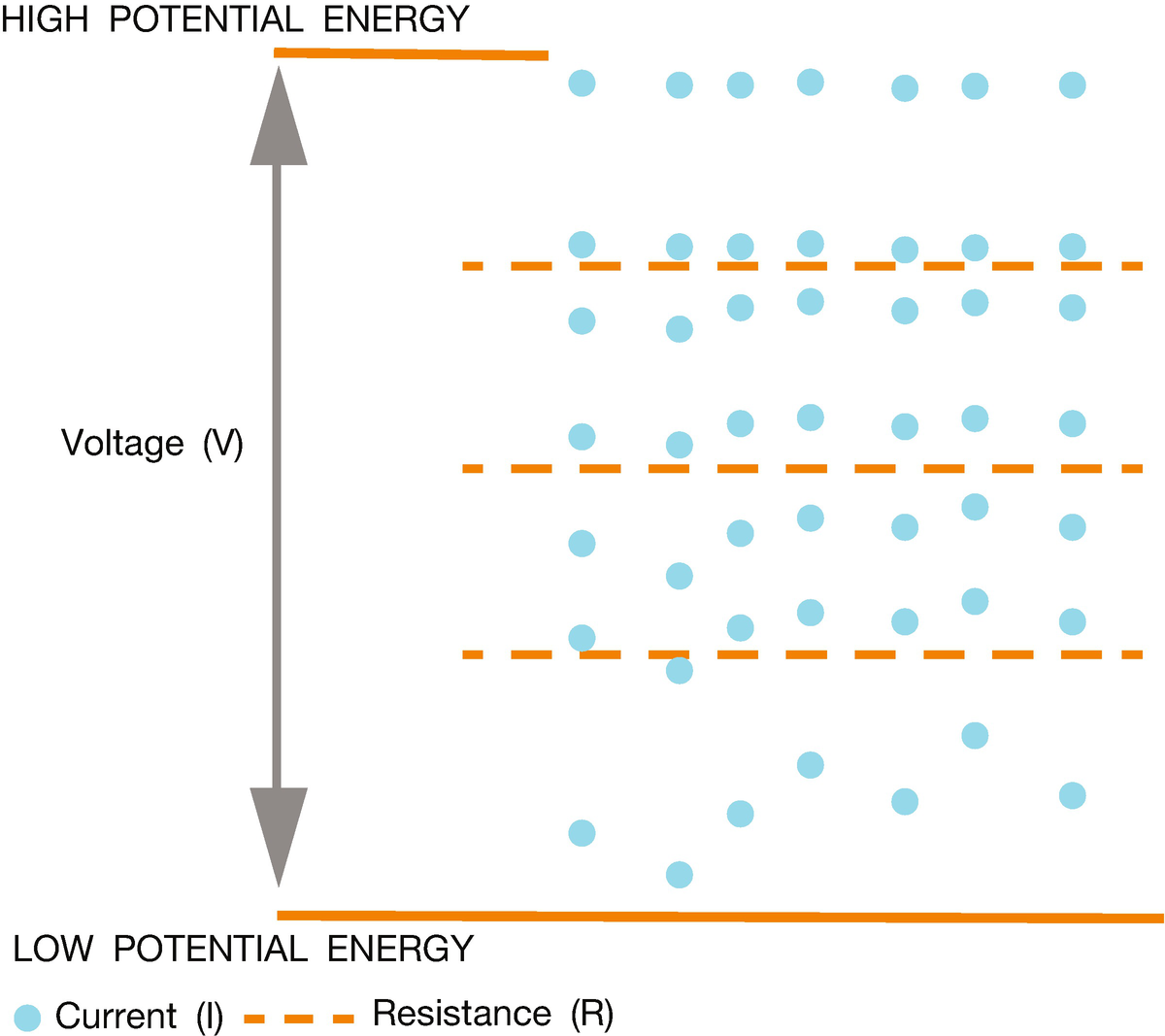
An interpretation of voltage, current, and resistance
Ohms Law
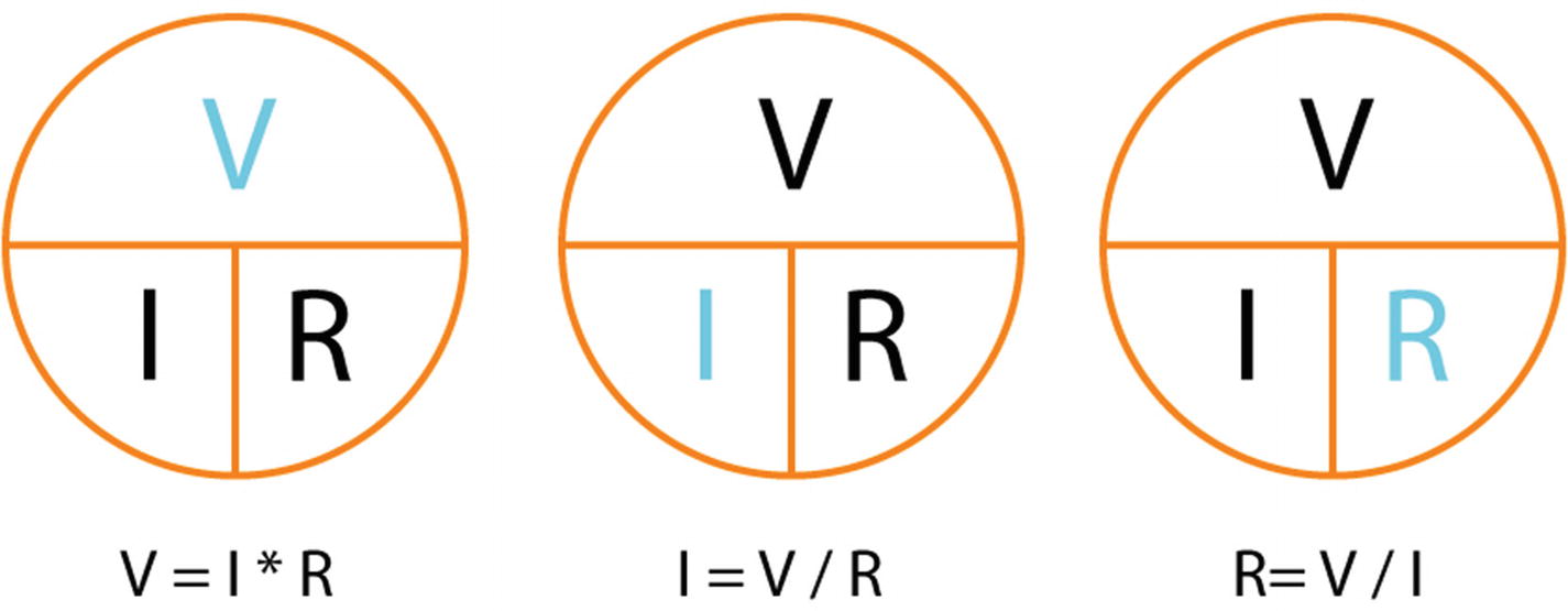
Ohms law
The components on a circuit use part of the energy in the circuit and turn it into another form of energy such as light or sound. All the energy on a circuit needs to be used by the circuit. If all the energy isn’t used up it needs to go somewhere, or this can cause it to overheat or catch fire. For example, if there is an LED on circuit and it receives too much energy, the light will be very bright and it can blow out. With Ohms law you can calculate the resistance, instead of V = I * R you can find resistance using R = V / I, resistance equals voltage divided by current.
Resistors
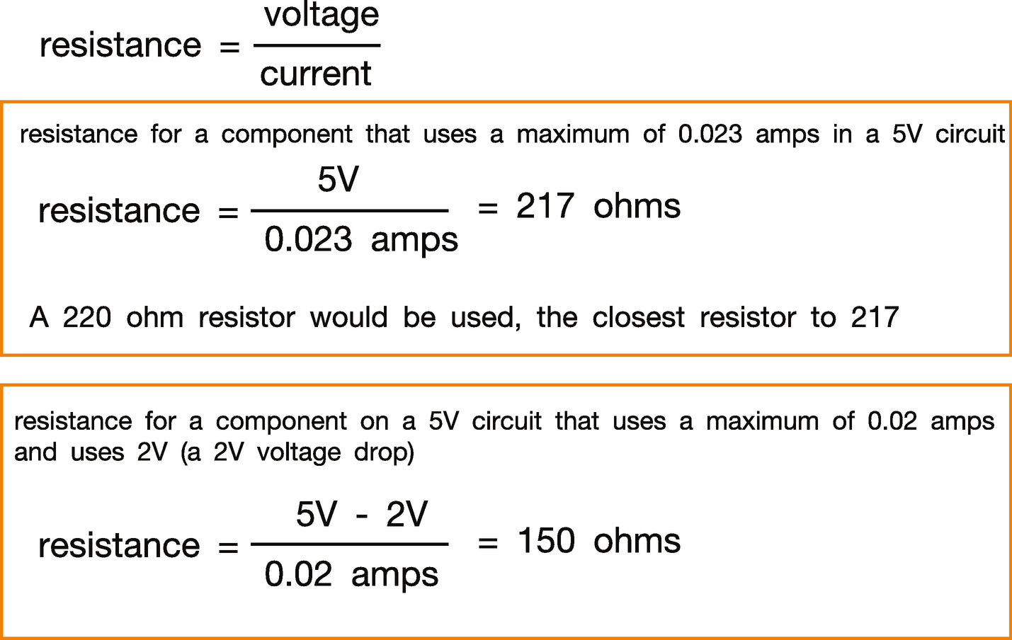
The formulae to find the resistance needed for a circuit
When you get a component, it should also have a data sheet, which may be online. This will give you information about the voltage drop and the maximum amps. This will allow you to work out what resistor you need for your circuit.
Resistors have a value measured in ohms; they have a color code to show that value. The value of the resistor tells you what amount of current it will dissipate.
Electronic Circuit Diagrams

A circuit diagram for an LED with a resistor
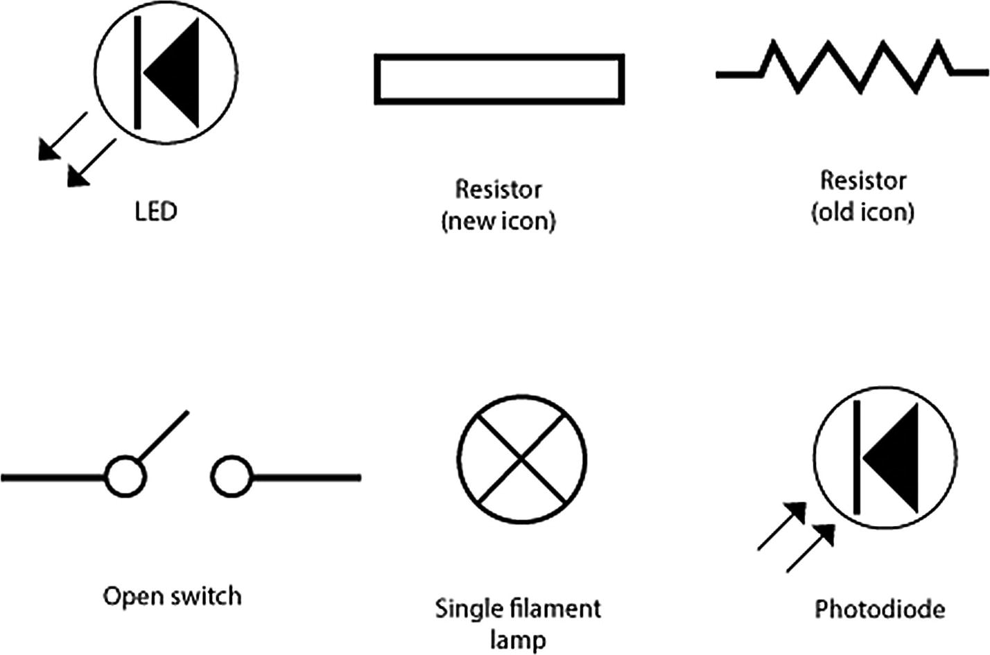
Some circuit diagram icons
Arduino Software
Arduino has its own programming language; it is a set of C and C++ functions. Arduino programs are called sketches, and they have a .ion extension. Arduino has its own integrated development environment (IDE) that has an editor and other tools to help you write and upload the code.
Downloading and Setting Up the Arduino IDE
- 1.
- 2.
The section “Download the Arduino IDE” contains links for the Mac and PC.
- 1.
Click the link Mac OS X 10.7 Lion or newer and choose JUST DOWNLOAD, or CONTRIBUTE & DOWNLOAD; both buttons are underneath the picture.
- 2.
Unzip the downloaded file.
- 3.
The Arduino icon will appear, just click on it to open the IDE.
- 1.
Click the link Windows Installer or Windows ZIP file for non-admin install depending on the Admin rights you have on your computer. Choose JUST DOWNLOAD, or CONTRIBUTE & DOWNLOAD.
- 2.
Unzip the download file.
- 3.
You should be able to open the IDE with the icon.
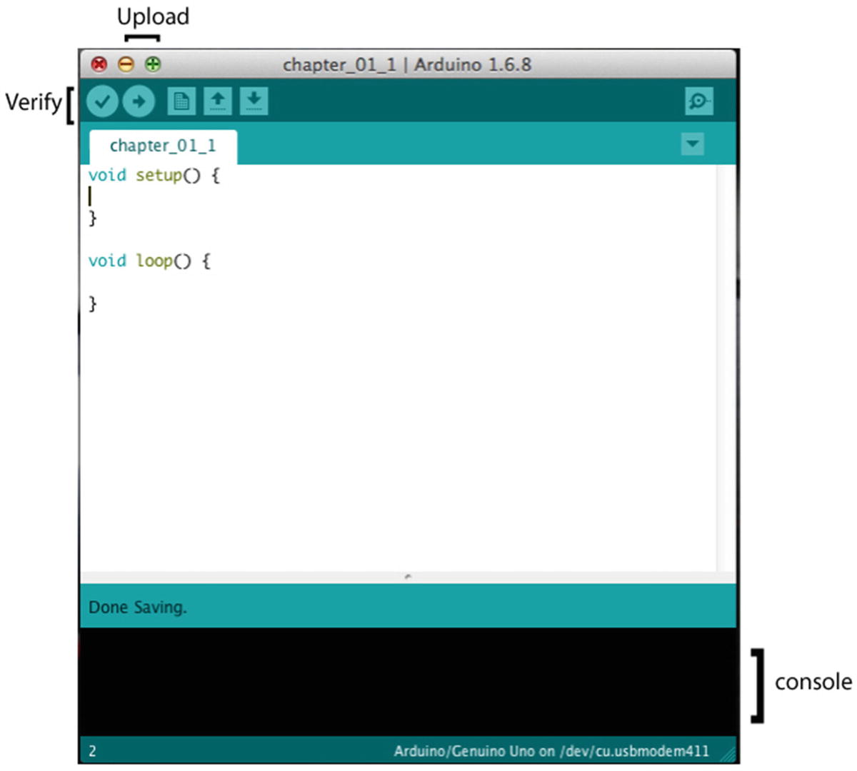
An Arduino IDE edit window
The sketch will contain two functions, setup and loop. There is a tick icon at the top of the page. This is pressed to verify that your code is written correctly. If there are any problems you will get a message in the console in red. The arrow icon is clicked when you want to upload the sketch to your Arduino. The console will show you messages connected to your sketch. It will show you any errors in your code and information when the sketch is verified and uploaded.
Connecting an Arduino to a Computer
You will need a USB 2.0 type B cable to connect an Arduino Uno to your computer. The USB will be used to send data to and from the Arduino as well as powering it. Different types of Arduinos will use different types of cable.
Once you’ve opened the IDE by double-clicking on the icon and connected the Arduino to your computer with the USB, you need to check the tools menu to see that the Arduino Uno is listed as the board and which port it is attached to. In the menu go to Tools/Board, and check that the board says “Arduino/Genuino Uno”; if it doesn’t, pick the Uno from the drop-down menu.
Ports
You will connect your Arduino to your computer by one of its USB ports; these ports have a number and in the Arduino IDE's tool menu, you need to check the port drop-down to choose the port.
Have a look in the Tools/Port menu to make sure that the USB port is being picked up. It will look slightly different depending which USB port you have plugged the Arduino into and if you are on a Mac or a PC. On a Mac it should say something like “dev/cu.usbmodem621 (Arduino/Genuino Uno)”. On a PC it will say something like “COM4 (Arduino/Genuino Uno).”
Write a Sketch
An Arduino has a built-in LED so the easiest sketch to write is one that controls this and makes it blink. It is the first sketch most people will write and is so common that the Arduino you have might already have it installed when you get it.
The Arduino IDE has a number of example sketches and blink is one of them. In the IDE, if you go to File/Examples/01.Basics you will see the blink sketch. You can either open it from there or copy it from the code in Listing 1-1. You will need to save it before you upload it.
blink.ino
The Code Explained
Whenever you open a new sketch you will always be given the setup and the loop functions. The setup function is called once when the program is first run. The loop function will keep looping and carrying out the commands in it while the Arduino has power. blink.ino is using the LED on the Arduino and controlling it. This LED is at digital pin 13 on the Arduino, so in the setup you use the pinMode function to say that pin 13 is being used as an output, and it will light up.
blink.ino explained
void setup() { pinMode(13, OUTPUT); } | setup is a function. Functions can return values, in this language you need to declare what it will return when you write the function. Both setup() and loop() don’t return anything so the void keyword goes before them. A function is made up of the function name followed by parentheses. The parentheses can be empty or can contain arguments. The argument is passed to the function when the function is called. The curly braces enclose the code for the function. |
pinMode(13, OUTPUT); | The Arduino library comes with a number of functions that you can use. pinMode is one of them and digitalWrite is another. When you use a function, it is called calling a function. To call a function you write the function name followed by parentheses. If the function is expecting arguments, they are put inside the parentheses. If it’s not they are left empty. The call to the function is finished with a semicolon. The semicolon lets the program compiler know that it is the end of the call or the command. |
You can verify the code to check that it is syntactically correct, then upload it to the Arduino. To verify it you press the tick arrow at the top of the code, and to upload it you click on the arrow icon. These are both shown in Figure 1-7.
Note The Arduino IDE is very sensitive to syntax errors, if you forget a “;” at the end of a command, or write something in lower case when it should be in upper case you will get an error. The IDE is pretty good at letting you know where the error is and they are normally easy to fix.
The Breadboard
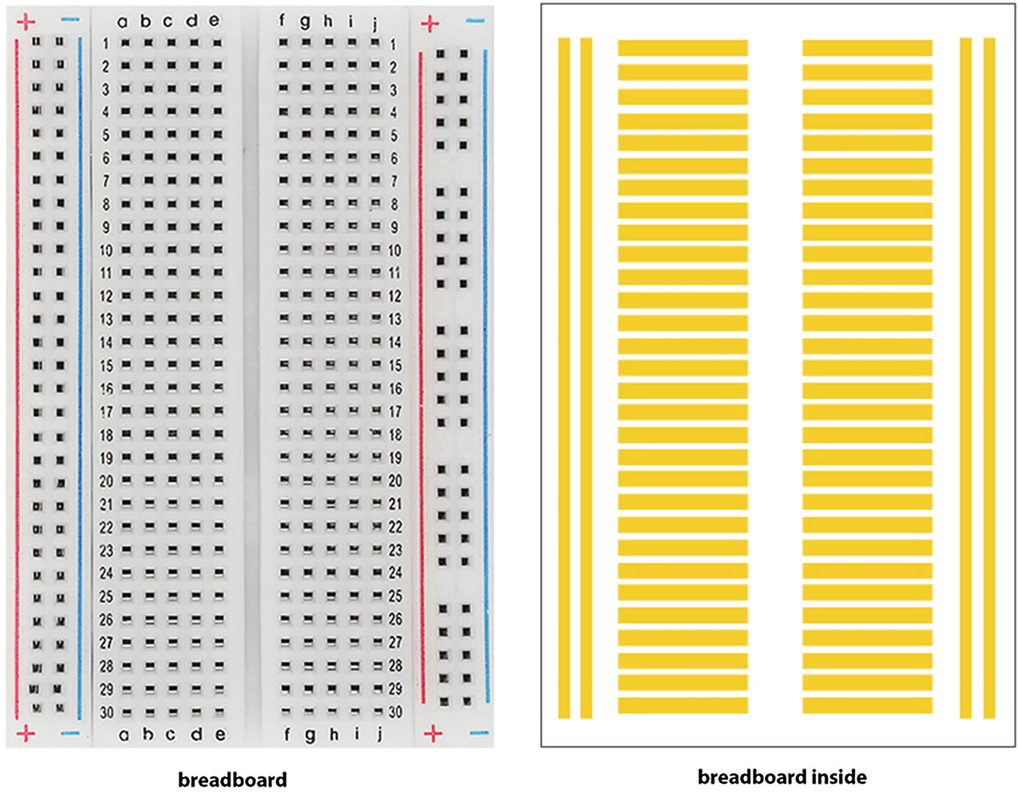
A Breadboard
Cables
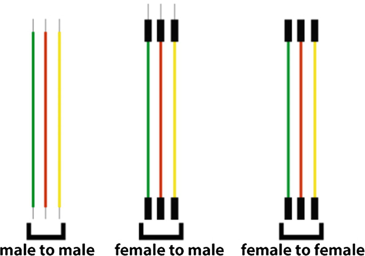
Cables
Digital and Analog
On an Arduino you can use digital input, digital output, analog input, and analog output. A digital input or output can have one of two states, on or off (high or low). The analog input or output can be between 0 and 1023 when 5V is being used. The following exercises in this chapter show examples of digital output and input, and analog input and output.
Caution
you must unplug your Arduino when you are connecting components. While it is connected to your computer, it has electricity running through it, which could cause an electric shock. If there is too much power for a component, it can pop or explode so you don’t want to be too close if that happens.
Digital Output
1 x Arduino Uno
1 x LED
1 x 220 ohm resistor

Components for the digital output exercise: 1. Breadboard, 2. LED, 3. 220 Ohm resistor, 4. Arduino Uno
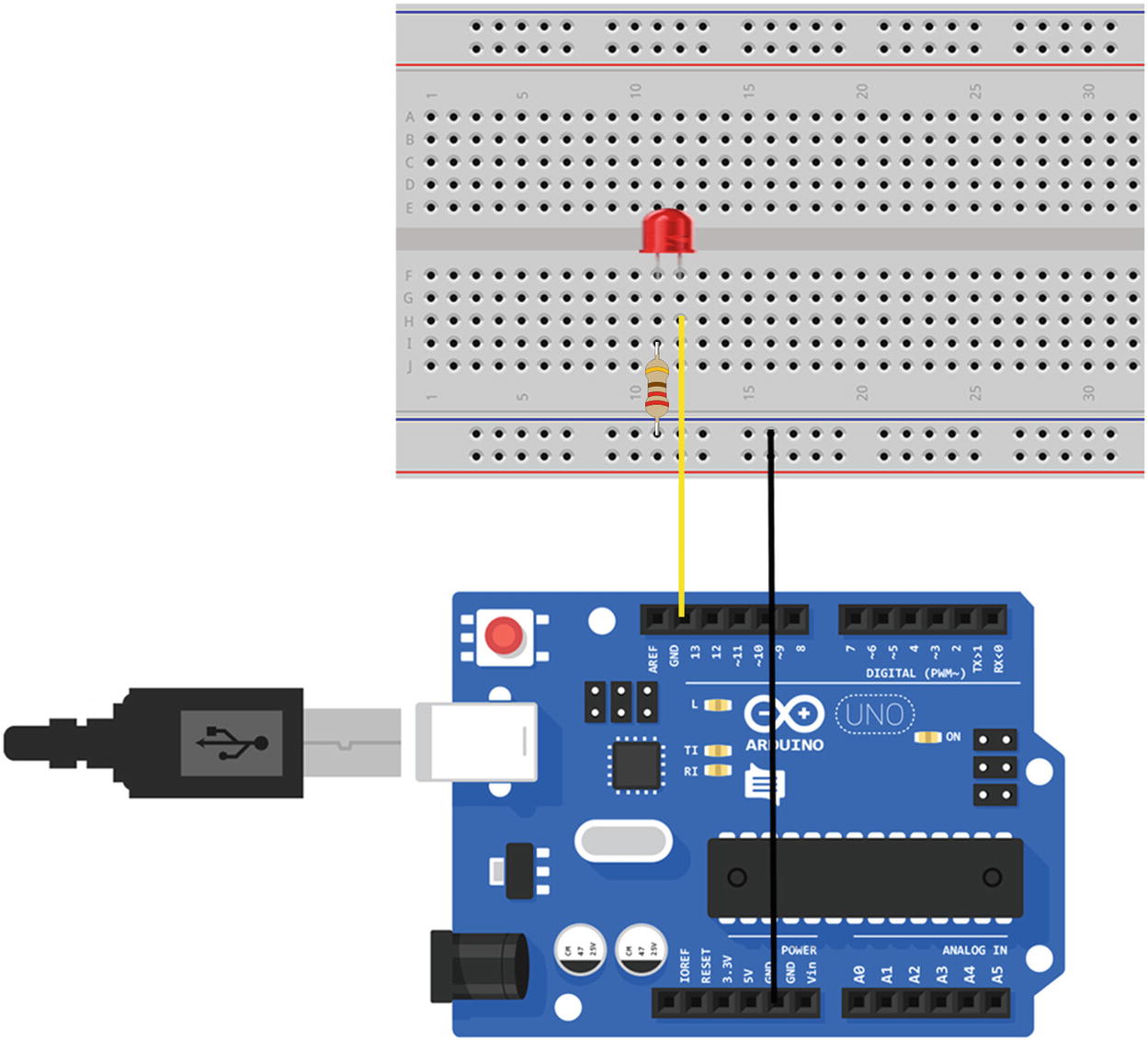
Setup for the components for the digital output exercise
Plug your Arduino back into your computer with the USB. If the last program you uploaded was the blink.ino, then you should see the LED blinking. If not, upload the blink.ino again.
Analog Output
Analog output and input produce a range of numbers that go up and down in sequence. On an Arduino some of the digital pins have a “~” symbol next to them. These pins are used for analog output and use PWM (pulse width modulation).
Pulse Width Modulation

Pulse width modulation
Analog Output

Setup for analog output
Create a new ino sketch, I called mine chapter_01_1.ino, and copy the code from Listing 1-2 into it.
chapter_01_1.ino
The Code Explained
chapter_01_1.ino explained
int analogOutPin = 9; | Pin 9 will be used for the LED; it is common practice to store this number in a variable that is used throughout the program. This makes it easier to see what the number represents throughout the program and also allows you to change the pin number once in the code if you decide to use a different pin number. |
int outputValue = 0; | A variable holds the value for the LED. |
if (outputValue >= 40){ outputValue = 0; } else { outputValue = outputValue + 1; } | An if else statement checks if something is true; if it is it does one thing and if not it does another. In this case it checks if the value of the variable outPutValue is greater or equal to 40; if it is it makes the variable contain the value 0, which turns the LED off, and if not it increases it by 1, turning the brightness on the LED up. |
analogWrite(analogOutPin, outputValue ); | The analogWrite function has two arguments: the pin number and a value, and in this case the value in outputValue is sent to the component attached to pin 9. In this case it is an LED, and this will change the brightness of the LED. |
Upload the sketch to the Arduino; you should see the LED increase in brightness then go off.
Digital Input
A good circuit to show a digital input is a switch button. The switch button is either up or down, and it is in one of two states, pressed or not pressed. It brings in another concept called Input Pullup.
There is a problem for an Arduino with a switch. When a switch is open, it does not complete a circuit, and there is no voltage so the Arduino doesn’t know what the input is; it could be 0 or it could be 1. As it doesn’t know you can get strange results, it creates noise as the input value is unknown and it tries to put something in. This problem is solved with pullup resistors; it sets a voltage when the switch is open.
Pullup resistors are built into the Arduino and can be accessed when using the pinMode() function by setting it to INPUT_PULLUP instead of just INPUT. The pin will read HIGH when the switch is open and LOW when it is pressed.
Digital Input
1 x Arduino Uno
1 x switch button
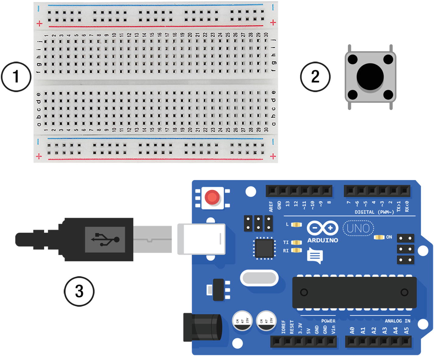
Components for the digital input exercise: 1. Breadboard, 2. Switch, 3. Arduino Uno

Setup for the components for the digital input exercise
Create a new sketch in the Arduino IDE, I called mine chapter_01_2, and copy in the code from Listing 1-3. Verify and upload the code to the Arduino. When you press the button the LED on the Arduino should light.
chapter_01_2.ino
chapter_01_2.ino explained
pinMode(buttonInput, INPUT_PULLUP); | You need to use INPUT_PULLUP as the second argument in the pinMode() function for the button switch. |
int sensorVal = digitalRead(buttonInput); | The value of the switch is read into a variable on each loop. |
if (sensorVal == HIGH) { digitalWrite(LEDOutput, LOW); } else { digitalWrite(LEDOutput, HIGH); } | An if/else statement checks if the switch is HIGH or LOW. Using the pullup means that the button’s logic is reversed. If it’s HIGH it means it’s up and so the LED is off. When it is LOW it is being pressed, which switched the LED on. |
Analog Input

An illustration of the analog input process
When a signal voltage is received it is tested against the internal reference at multiple points on the line. For example, it checks if the input is greater than 0; if not, it checks if it’s greater than the next number on the reference and keeps checking until it is. That point becomes the input number.
Analog Input
This exercise uses a potentiometer as an analog input. The potentiometer turns LED on the Arduino on and off when it is turned about halfway.
1 x Arduino Uno
1 x potentiometer
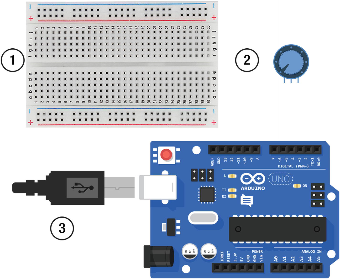
Components for the analog input exercise: 1. Breadboard, 2. Potentiometer, 3. Arduino Uno
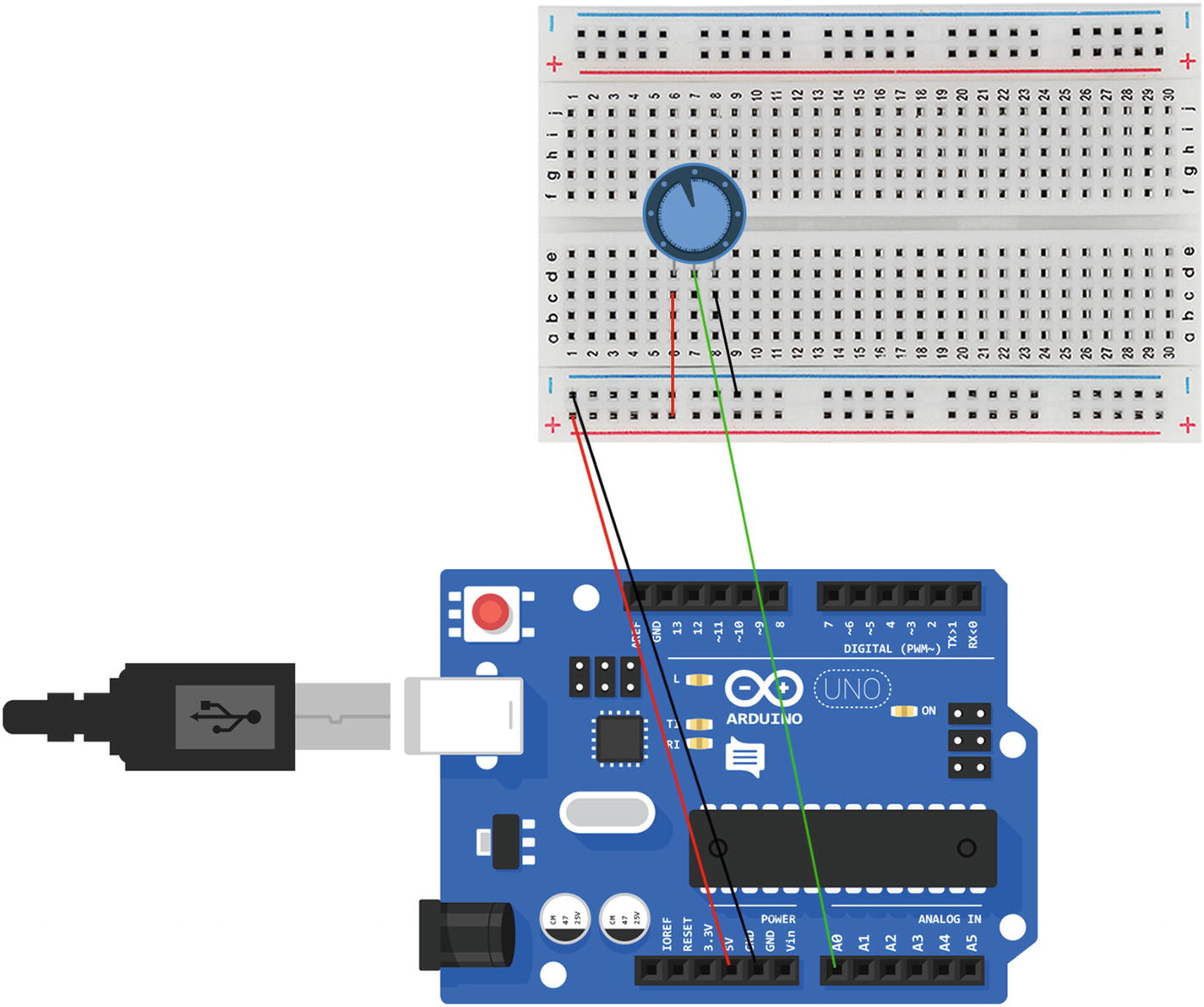
Setup for the components for the analog input exercise
Open a new sketch. I called it chapter_01_3; and then copy the code from Listing 1-4.
chapter_01_3.ino
Verify the sketch and plug the USB back into your computer to upload the sketch to the Arduino. Now when you turn the potentiometer just past halfway, the LED on the Arduino should come off and on.
The code is very similar to the previous sketches in this chapter. The main difference is the variable for the analog pin int pinAnalogInput = A0; The analog input goes through pin A0;
Summary
This chapter was a basic introduction to the Arduino. It looked at how a circuit works and the analog and digital input and output. These are the basic blocks for Arduino that will be built on through the book. The next chapter will get you started with JavaScript and building a web server that will be able to receive data sent from an Arduino.