
In Chapter 2 you learned how to create a web server with Node.js and use it to send data to a web page. In this chapter you will start sending data from an Arduino to a Node.js server and use the data on a web page.
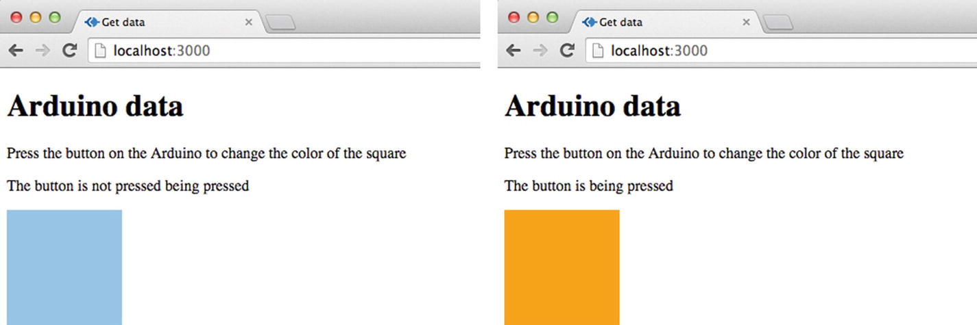
Two possible outcomes of the exercise in Chapter 3
Introduction to Serial Port
A serial port transfers data in and out of a computer in single bits one after another. A bit can have a value of 0 (low/off/false) or 1 (high/on/true). These bits can be joined together to transfer more complex data, and different numbers of bits have different names. Eight bits is a byte, a KiloByte (KB) is 1024 bytes (1024 x 8 bits), and a Megabyte (MB) is 1024 kilobytes. As the bits can only be 0 or 1 they are called binary data.
With Arduino's you can send serial data back and forth from your computer through the USB port. Every Arduino has a serial port, some more than one. The Arduino Uno uses RX(pin 0) and TX(pin 1) to communicate. If you are using serial you cannot attach anything to pins 0 and 1. The Arduino IDE has a built-in serial monitor to view serial data.
When you connect your Arduino to your computer it will be attached to one of the computer’s serial ports. You need to know which port it is attached to, as you will need to reference it in your Node.js application.
Finding the Serial Port
On a Mac and a Windows PC the serial port number looks slight different. On a Mac it will look something like this: /dev/tty.<type of input and port number> or /dev/cu.<type of input and port number>. In Windows it will looks something like this: COM<port number>.
- 1.
With the Arduino attached, open the Arduino IDE. In the menu click on the Tools menu and then hover over the Port menu; you will see all the devices attached to serial ports, and the serial port for the Arduino will look something like this: /dev/tty.usbmodem<port number> (Arduino/Uno) on a Mac and on a PC it will look like COM<port number>.
- 2.
On a Mac open a terminal window and type ls /dev/tty.usbmodem*. You should get an output similar to /dev/tty.usbmodem<port number>.
- 3.
On a PC, open the device manager and open the Ports (COM & LPT) menu, and you should see something like Arduino Uno COM<port number>.
Serial Data and Arduino
Arduino serial functions
Command | Result |
|---|---|
Serial.begin(9600) | The begin function sets the transmission rate for the serial data; it is measured in bits per second and is called the baud rate. |
Serial.end() | Signals the end of serial communication and releases pins RX and TX so they can be used for other inputs and outputs. |
Serial.write() | Writes binary data to the serial port. |
Serial.println() | Prints out serial data. |
The Baud Rate
The Baud rate sets the rate for transmitting data through the serial port. It is measured in bits per second. The rates that can be used with an Arduino are 300, 600, 1200, 2400, 4800, 9600, 14400, 19200, 28800, 38400, 57600, or 115200. The maximum speed you can set a baud rate will depend on your device. If the device can't process the higher speed then some of the data won't be registered, and you will lose data. The rate 9600 is a common baud rate for an Arduino.
Setting Up The Arduino Circuit
In this chapter you will be connecting a switch button to an Arduino and using the Serial functions to find out if the button is pressed down or not.
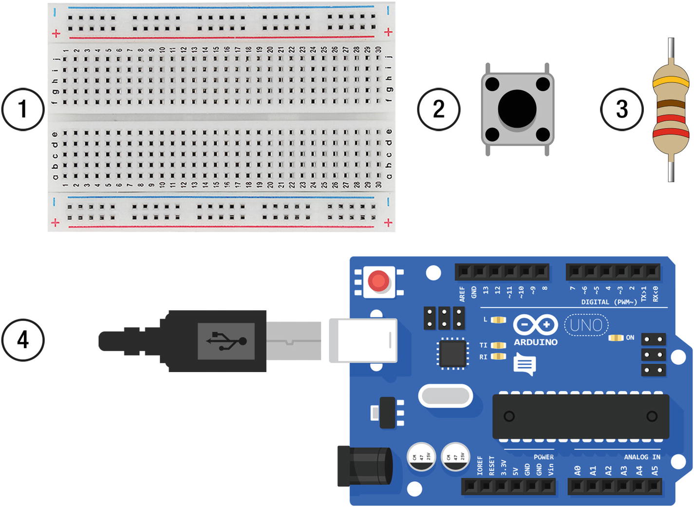
1. Breadboard, 2. Switch button, 3. 220 ohm resistor, 4. Arduino
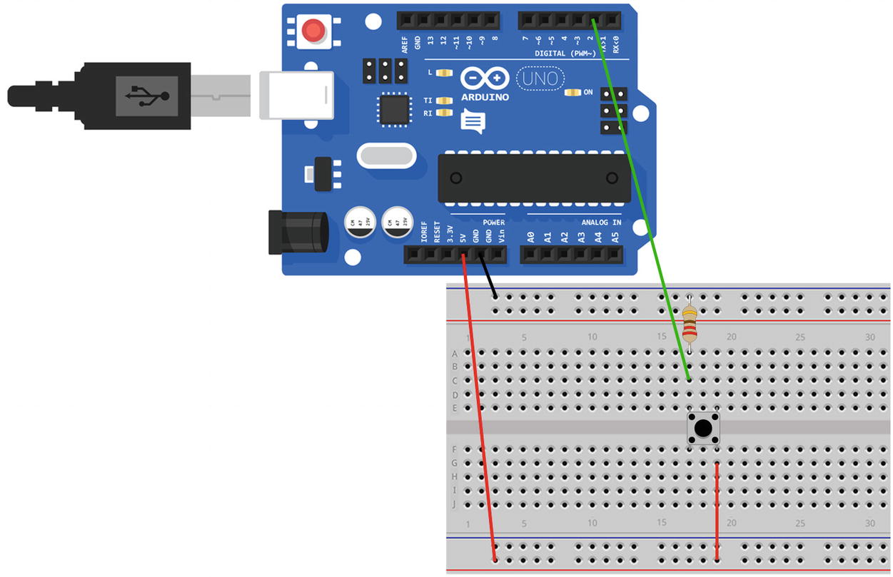
The circuit setup
Write The Arduino Code
- 1.
In the Arduino IDE menu choose Tools/Board and choose Arduino/Genuino Uno.
- 2.
In the Tools/port menu choose the port that the Arduino is connected to, and it will say something like COM3 (Arduino/Genuino Uno) on a PC or /dev/cu.usbmodem621 (Arduino/Genuino Uno) on a Mac.
Then choose file/new to open a new file. Save the file as chapter_3. Copy the code from Listing 3-1.
chapter_3 code
The Code Explained
chapter_3.ino code explained
int switchButton = 2; | This code creates a variable to hold the number for the switch input into the Arduino. On the Arduino it is connected to digital pin 2. |
Serial.begin(9600); | This function sets the baud rate that the data will be transferred at. |
pinMode(switchButton, INPUT); | pinMode is a function that sets the mode for the pins, and INPUT is the default and sets it up to receive data. It is being passed to the switchButton variable that holds the digital pin number. |
int buttonState = digitalRead(switchButton); | The variable buttonState holds the data coming from digital pin 2, which the button is connected to. It will either be high if the button is being pressed or low when it's not. |
if(buttonState == HIGH){ Serial.println("1"); }else{ Serial.println("0") ; } | The if statement checks if the buttonState is HIGH. If it is, the button is being pressed and Serial.println will send “1” to the serial port. If it's not it, the else statement will send “0” instead. |
delay(500);and | As the code is in a loop you can delay the loop starting again. If you don't do this, code might not have finished executing before the loop starts again and you can lose data. The delay function uses milliseconds, and 500 is half a second. You need to get the balance right with the delay; you don’t want to lose data but if you make the delay too long, you might miss the button being pressed. |
Run The Arduino Code
Check that the code is correct by clicking on the tick icon, and then send the code to the Arduino by clicking on the arrow icon.
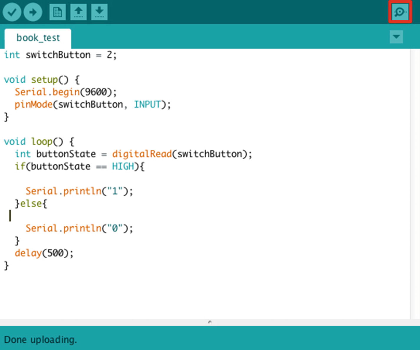
How to open the serial port monitor
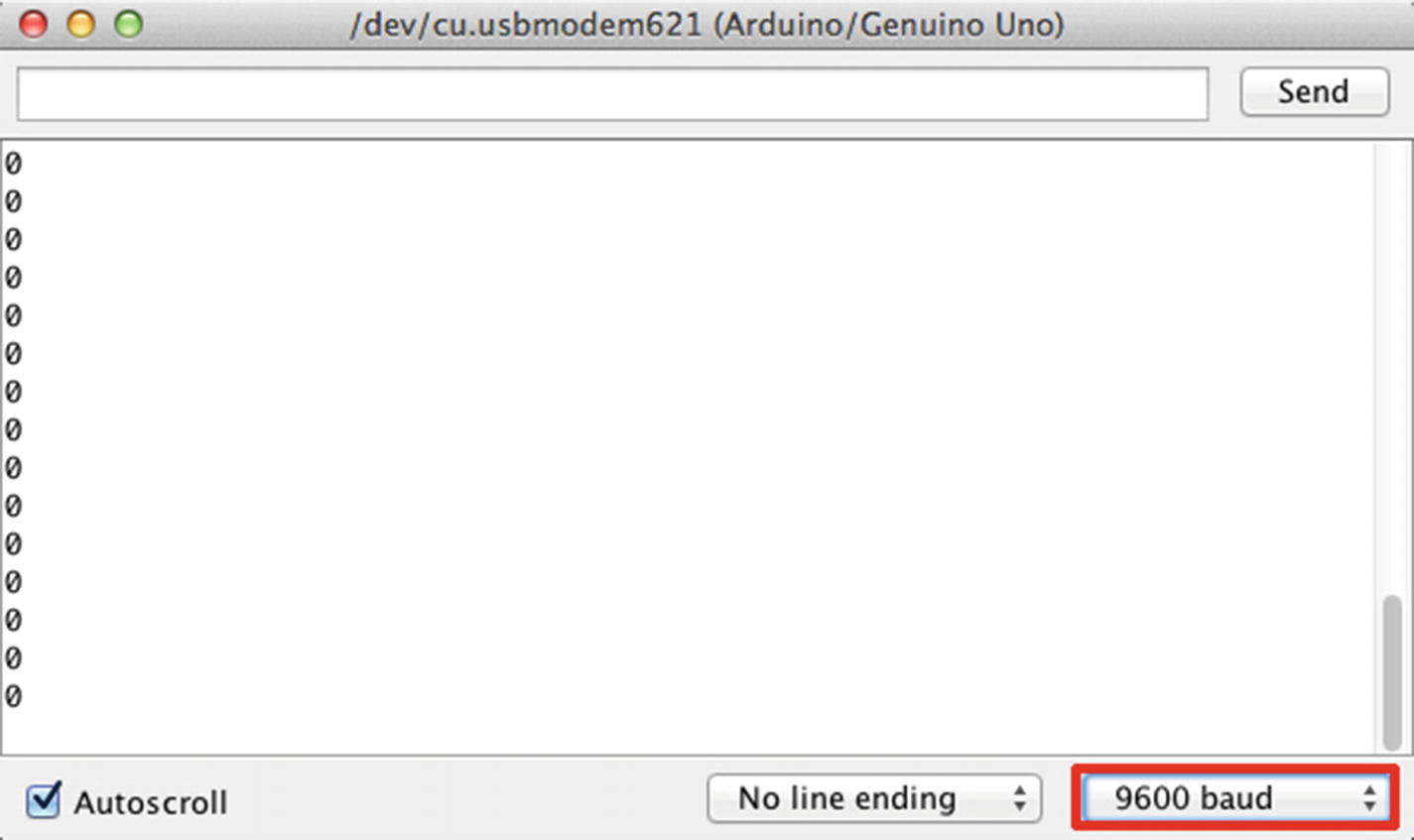
The drop-down changes the baud rate.
Note You need to close the serial port monitor in the Arduino IDE before using a web application that is using the serial port. If you don’t, you will get an error that the port is already in use.
Using the Data on the Front End
Now that you can see the serial data in the Arduino the next step is to send it to a Node.js server so that it can be displayed on a web browser. The Node.js application in this chapter will take in data from the Arduino and use Socket.io to pass the data to the front end.
SerialPort Library
One of the libraries you will import is the SerialPort library. This library allows you import data from the Arduino, via the serial port, into Node.js.
To open a port with the library in Node.js you need to include a path to the Library and create a new port object.
The data coming through the SerialPort library is a buffer object. A buffer object is the stream of bits (binary data) that is coming through the serial port. JavaScript does not handle binary data very well. SerialPort has a readLine parser that converts the binary data into strings. The code looks like this:
The “ ” is the way to create a new line in JavaScript. The readLine converts the binary data into lines of text. It knows that it is the end of the current data stream when it sees the newline character and so it separates the different streams of data.
There a number of functions in the SerialPort library, but we will be using a few in this book. You can find more information about the SerialPort library in Appendix B.
Downloading the SerialPort Library
You will be using npm to install the SerialPort library. On a PC you will need to download a couple of other packages before using npm to install SerialPort. On a Mac you will be able to download it without any extra libraries so you don’t need to do the following steps.
- 1.
First, install node-gyp, as it is used for compiling native add-on modules in Node.js. Open a console window and type in npm install -g node-gyp. You can find more information at https://github.com/nodejs/node-gyp#installation .
- 2.
Extra build tools for windows also need to be installed. These have to be installed with a console window running in administration mode. Open the CMD.exe by right-clicking on the Windows menu and choose CMD.exe(run as Administrator) or type it in the search bar. In the console type npm install -g --production windows-build-tools. You can find out more about the tools at https://github.com/felixrieseberg/windows-build-tools ; this might take a few minutes to install.
Create a Node.js Application
The directory structure for this chapter will be the following:
- 1.
Create a new folder to hold the application. I called mine chapter_03.
- 2.
Open the command prompt (Windows operating system) or a terminal window (Mac) and navigate to the newly created folder.
- 3.
When you are in the right directory type npm init to create a new application; you can press return through each of the questions, or make changes to them.
- 4.
You can now start adding the necessary libraries; to download Express.js at the command line type npm install [email protected] –save.
- 5.
Then install ejs, type npm install [email protected] –save.
- 6.
When that's downloaded, install serial port. On a Mac type npm install [email protected] --save on a Windows PC type npm install [email protected] --build-from-source.
- 7.
Then finally install socket.io, type npm install [email protected] –save.
If you look at your package.json file you should see the following dependencies:
Now you can write the code for the application. In the root of the chapter_03 folder create a file called index.js copy in the code from Listing 3-2.
Note Throughout this book you will be using the serial port library in index.js. You will need to add into index.js a reference to the serial port that your Arduino is connected to. In the code where it says <add in the serial port for your Arduino> on a Mac, change it to ‘/dev/tty.usbmodem<port number> ’ and on a PC you change it to ‘COM<port number> ’. You need to keep the ‘ ’ and remove the < > symbols
index.js code
Remember to add in the serial port you are using. If you run this code now there will be an error. It references an index.ejs file that hasn’t been created yet.
The Code Explained
index.js explained
var SerialPort = require('serialport'); | This brings the SerialPort library into the Node.js application and stores it as a variable. |
var serialport = new SerialPort('<serial port>' | The code creates a new serial port object. You need to add in the serial port that your Arduino is connected to in between the < >. On a Mac it should look like /dev/tty.usbmodem<port number> and on a PC it should look like COM<port number>. |
{ parser: SerialPort.parsers.readline(' ') }); | The data gets parsed using readline, the ‘ ’ creates a new line which separates each line of data. |
serialport.on('open', function(){ | The open event is emitted when the port is opened. You can specify events when the serial port is open, and in the code there is a console log so you know if it has opened. |
serialport.on('data', function(data){ | The data event starts to monitor for new data, and the function is passed to the new data. |
data = data.trim(); | The function gives you access to the new data, but first it needs to be trimmed of any white space before or after the character. |
socket.emit('data', data); | The data is passed to the front end using the socket.io function emit; it has a reference id of ‘data’. |
Interacting With A Web Page
The data from the Arduino is going to be used to update a web page. The color of a square will change each time the button is pressed. A variable will keep track of the current data sent from the Arduino. When new data comes into the page, there is a JavaScript function that checks if the new data is different from the current data.
If it is and the data is the string “1,” then the function will pick at random an element from an array that is a list of colors. It then updates the color of the square. It also updates a piece of text and the current variable so the new data becomes the current data.
If the new data is “0” the color of the square doesn’t change, but a piece of text gets updated. Again the current variable will be updated with the new data.
You now need to create an index.ejs file in the views folder; first create a views folder in the root of your application and then create a file called index.ejs inside it. Copy the code from Listing 3-3 into the index.ejs file.
index.ejs code
Now in a console window navigate to the route of the application and type nodemon index.js or node index.js to start the application. Open a browser and go to http://localhost:3000/ to see the application running.
Each time you press the button the color of the rectangle will change. As the color in the array is picked at random it may pick the same color as the current color. If you wanted to make sure the rectangle changed color, you could create a variable for the current color and check that the new color is different.
The Code Explained
index.ejs explained
<svg width="120" height="120" viewBox="0 0 120 120"> | This creates a scalable vector graphic (SVG) square with a width, height, and color. There will be details on SVG’s in Chapter 4. |
var current = "0"; | This creates a variable that holds the current value of the serial data. This variable will be used to check if the data from the serial port has changed. |
var shape = document.getElementById('change-color'); | Shape is a variable that holds a reference to the SVG rectangle. The variable is used to update the color of the rectangle. It finds it using the SVG’s id. |
var buttonState = document.getElementById('button-state'); | buttonState is a variable that holds a reference to a span element. It finds the element by its id and will update text within it. |
var colorArray = ["LightSkyBlue", "LightSlateGray","DarkOliveGreen", "orange", "DarkRed", "gold", "purple"]; | The variable colorArray holds an array of different color names. |
socket.on("data", function(data){ | The socket.on function is listening for data coming from a socket.emit with the id of ‘data’ and passes the incoming data to a function. |
if(data === "1"){ | The if statement checks if the new data is the string “1.” If it is, the text on the web page changes and another if statement is called. |
if(data !== "current"){ | This if statement checks if the new data is the not the same (!==, not equal to) the current data. If it is not the same it carries out the code within the statement. |
var newColor = colorArray[Math.floor(Math.random() *colorArray.length)]; | This piece of code chooses a color from the colorArray. The JavaScript Math.random() function is used to pick a random number between 0 and the number of the elements in the array. It’s multiplied by (the * symbol) the length of the array so it only chooses a number within the array length. |
shape.style.fill = newColor; | Using the variable shape, the fill style of the SVG is changed to the new color. |
else{ buttonState.innerHTML = "not pressed"; } | If the value of the new data is not “1,” then the HTML of the span with the id button-state is changed to the string “not pressed.” |
current = data; | The variable holding the value of the current data needs to be updated with the value of the new data. |
Summary
You should now have a working application with a web page that updates when you press the button attached to the Arduino. There were a lot of new concepts in this chapter, and Chapter 4 will look at these in more detail.