
9
NEXT-GENERATION ETHERNET PASSIVE OPTICAL NETWORKS: 10G-EPON
1G-EPON, which is part of IEEE 802.3-2008 [1–3], is considered to have sufficient capacity for the next few years [4], provided that current bandwidth demand growth is maintained [5, 6]. Proprietary nature of higher-speed EPON solutions [7] meant that there was a limited supplier base and restricted interoperability between system integrators, which initially caused some concerns about deployment of such systems. This is what the market situation was at the time of 10G-EPON Call for Interest, presented during one of the IEEE plenary meetings in 2006 [8]. However, recent adoption of 2G-EPON specifications by CCSA (http://www.ccsa.org.cn/english) indicates a growing popularity of this solution at least on the Chinese market.
Taking into consideration that more than 30 million active ports of 1G-EPON have already been deployed up to date (2010), 10G-EPON seems like a natural step in the evolution toward more multimedia-rich, bandwidth-intensive applications of the future, where high-definition, distributed contents and file sharing as well as networked hardware play increasingly important roles. Given the successful history of IEEE equipment and a number of identified market applications, 10G-EPON will certainly enjoy deployment scales beyond anything that competitive PON architectures have ever seen. Providing 10 times more raw bandwidth than current 1G-EPON (approximately 8.9 Gbit/s is available for subscriber data due to mandatory FEC for all 10 Gbit/s links), it is poised to deliver the bandwidth required for next-generation applications following an evolutionary scenario rather than forcing operators to completely replace legacy 1G-EPON equipment. Assuming that market models conceived for 10G-EPON P802.3av project become reality in the near future, this new addition to EPON architecture will enjoy deployment costs per subscriber comparable to current 1G-EPON equipment, while allowing for much higher subscriber density at the CO, securing ROI for already deployed hardware.
9.1 ACRONYMS
| APD | Avalanche photodiode |
| BER | Bit error rate |
| ChIL | Channel insertion loss |
| CRC | Cyclic redundancy check |
| CSMA/CD | Carrier sense multiple access/collision detection |
| DBA | Dynamic bandwidth allocation |
| DML | Directly modulated laser |
| EML | Externally modulated laser |
| EPON | Ethernet passive optical network |
| FEC | Forward error correction |
| FIFO | First in, first out |
| GMII | Gigabit MII |
| IP | Internet protocol |
| IPG | Interpacket gap |
| IPTV | Internet protocol TV |
| LA | Limiting amplifier |
| LLC | Logical link control |
| LLID | Logical link identificator |
| MAC | Medium access control |
| MACC | MAC client |
| MDI | Medium-dependent interface |
| MII | Media interface independent |
| MPCP | Multipoint control protocol |
| MPCPDU | MPCP data unit |
| ODN | Outside distribution network |
| OLT | Optical line termination |
| ONU | Optical network unit |
| P2MP | Point to multipoint |
| P2P | Point to point |
| PCS | Physical coding sublayer |
| PIN | Positive, intrinsic, negative diode |
| PMA | Physical medium attachment |
| PMD | Physical medium dependent |
| PON | Passive optical network |
| QoS | Quality of service |
| ROI | Return on investment |
| RS | Reconciliation sublayer |
| SLD | Start of LLID delimiter |
| TDMA | Time division multiple access |
| TF | Task force |
| TIA | Transimpedance amplifier |
| TQ | Time quantum |
| WDM | Wavelength division multiplexing |
| XGMII | 10 Gbit/s MII |
9.2 10G-EPON ARCHITECTURE
The IEEE 802.3 Working Group is historically focused only on the two bottom layers of the layered Open Systems Interconnection (OSI) reference model, namely the physical and data link layers, leaving network architecture and higher level management to the IEEE 802.1 Working Group and other Standard Development Organizations. To facilitate reuse of individual elements comprising 802.3 layers, they are further divided into sublayers, connected by standardized interfaces. This enables projects like P802.3av to build on specifications from earlier projects (e.g., P802.3ae 10GE or P802.3ah Ethernet in the First Mile), by introducing extensions necessary to support new functionalities. Such a modular construction of 802.3 specifications translates directly into lower cost and faster development cycles for new equipment, because experience and design from the previous generation of devices (or even other product lines) can be applied directly to new products.
The physical sublayer is subdivided into six blocks:
1. MDI specifies characteristics of the electrical signals which are received from/transmitted to the underlying medium. Additionally, it also contains definitions of mechanical and electrical interfaces used to exchange data between PMD and medium.
2. PMD specifies the basic mechanisms for exchange of data streams between medium and PCS sublayer. The bottom part of PMD contains physical devices, like receiver and transmitter.
3. PMA sublayer specifies functions responsible for transmission, reception, clock recovery, and phase alignment.
4. PCS defines a set of functions, which are responsible for converting a data stream received from xMII into codewords, which can then be passed through PMA and PMD and finally transmitted into the medium. In the receive path, PCS performs the reverse function—that is, decodes the received data and recreates the original data stream. PCS houses such critical functionalities as data decoder/encoder, FEC encoder/decoder, data detector (ONU transmit path only), and scrambler/descrambler as well as gearbox, adjusting the data rates between PCS (bursty transmission) and PMA (continuous data stream).
5. xMII specifies a standardized interface between the MAC and PHY layers. This is one of the major interfaces in the 802.3 stack, allowing for modular interconnection of various PHY layers to MAC.
6. RS maps MAC service primitives into xMII signals, effectively transferring data into PHY and vice versa. In the EPON architecture, RS plays also one more critical role: It is responsible for LLID insertion and filtering for all data passing from MAC or PHY.
The data link layer is further subdivided into three major sublayers:
1. The MAC sublayer defines a set of medium independent functions, enabling MAC clients to exchange data with their link peers. MAC supports general data encapsulation (including framing, addressing, and error detection) and medium access (collision detection and deferral process for shared medium environment—not used in case of P2P and P2MP systems).
2. The MAC control sublayer is optional and performs real-time control and manipulation of MAC operation. MAC control sublayer specifications are open, which allows new projects to extend MAC functionality while leaving MAC itself intact.
3. LLC is already considered out of the scope of 802.3, which means that all underlying sublayers (MAC and MAC control) are specified in such a way that LLC is completely transparent to them.
P802.3av, as per its Project Authorization Request approved in September 2006, was focused exclusively on extending the EPON network architecture by adding a set of new PHYs, capable of supporting higher data rates (10 Gbit/s effective) and power budgets with higher ChIL. Minor modifications to management and MPCP sublayer were identified also as part of the project, though their scope was limited to new PHYs. There were two reasons why P802.3av made no changes to 1G-EPON specifications, even if that could potentially facilitate coexistence: (i) the P802.3av TF had a mandate to introduce changes into existing 1G-EPON specifications, and (ii) introduction of changes to a standard describing mass-deployed equipment might potentially cause compliance issues, thus was discouraged. The approval of IEEE 802.3av 10G-EPON standard on September 11, 2009, the numerous and geographically varied attendance of the meetings, the deep involvement of many companies, and commercial availability of 10G-EPON equipment from the first system suppliers come as a result of more than three years’ worth of continuous work of a dedicated group of experts. It is anticipated that the first commercial deployments of 10G-EPON systems will become a reality by Q4 2010, further fueling market success of this technology.
9.2.1 Physical-Medium-Dependent (PMD) Sublayer
PMD specifications are included in Clause 75 of IEEE 802.3av, representing the result of more than 2 years of technical discussions and a number of compromises reached between major parties involved in this process. A number of ad hoc activities were carried out, focusing on high-power budget and high split systems, link channel model, nonlinear effects in the fiber, and so on, the conclusions and recommendations of which are available on the official website of P802.3av TF (http://www.ieee802.org/3/av/).
9.2.1.1 PMD Naming Convention.
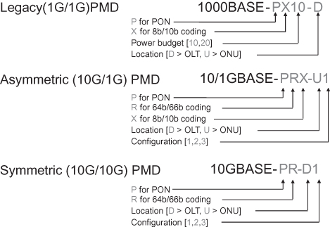
PMD naming generated a long and very hot discussion, even though it seems like a minor issue compared with technical topics, which needed to be closed at the time. Symmetric, 10 Gb/s PMDs were quickly stabilized in the form presented in Figure 9.1c, while asymmetric PMDs (10 Gb/s downstream, 1 Gb/s upstream) proved to be more tricky and took time to reach the final version presented in Figure 9.1b. The legacy 1G-EPON PMD naming convention is presented in Figure 9.1a, for reference. Note also that there is no 10GBASE-PR-U2 PMD, since 10GBASE-PR-U1 is shared between PR10 and PR20 power budget classes.
Figure 9.1. PMD naming conventions for (a) 1G-EPON, (b) 10/1G-EPON, and (c) 10/10G-EPONversions.
9.2.1.2 Power Budgets.
Power budgets in the 10G-EPON specification describe P2MP media supported by the given PMD, similarly to their definition in 1G-EPON. However, due to the existence of symmetric and asymmetric data rate PMDs, when referring to (for example) a low-power budget, it is not clear whether symmetric or asymmetric PMD is meant. For that purpose, a new designation of power budget class was introduced, which can be seen as a superset comprising both PR-type and PRX-type power budgets, characterized by the given ChIL. Therefore, a PRX-type power budget describes an asymmetric rate PHY, operating at 10 Gb/s downstream and 1 Gb/s upstream over a single single-mode fiber, while a PR-type power budget describes a symmetric rate PHY, operating at 10 Gb/s downstream and 10 Gb/s upstream, also over a single single-mode fiber. Furthermore, each power budget is identified with a number designating its class, where “10” represents low power budget, “20” represents a medium-power budget, and “30” represents high-power budget. Table 9.1 provides an overview of 10G-EPON power budgets and their association with power budget classes.
TABLE 9.1. Major Power Budget Parameters and Their Mapping into Power Budget Classes
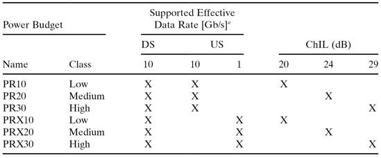
a Effective data rate at MAC level rather than channel data rate observed at the PHY.
9.2.1.3 Implementation Choices for Individual Power Budget Classes.
The following discussion presents the outcome of technical decisions, included in the standard in the form of PMD parameter tables in Clauses 75.4 and 75.5. Note that the standard provides specific numbers for individual parameters, while not describing the motivation behind them. Additionally, specific technical solutions supporting particular power budgets are also not indicated in the standard, leaving it up to implementers to decide what hardware solution to choose. It is worth noting that during the design process, special attention was paid to PMD sharing across at least two power budget classes to minimize the number of PMD elements to be developed.
Several PMDs share either transmit or receive path parameters; for example, PR(X)–D1 and PR(X)-D3 PMDs share a common transmitter design, and PR(X)–U1 and PR-U2 PMDs as well as PR-D2 and PR-D3 share a common receiver design. Additionally, in the case of symmetric 10/10G-EPON systems, PR-U1 (ONU) PMD is shared between two power budgets, namely PR10 and PR20, meaning that PR10 and PR20 ONUs are exactly the same. This means that the most cost-sensitive devices (ONUs) can be produced in larger quantities, leading to a faster decrease of their price.
Table 9.2 presents a typical ONU and OLT PMD design for all target power budget classes, with the indication of individual design choices as well as target transmit power and receive sensitivity levels.
TABLE 9.2. Target Implementation of 10G-EPON PMDs
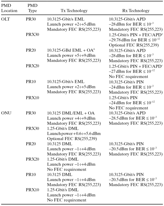
aAPD is typically used to avoid the use of FEC in upstream channel.
bCurrently, such transmitters are under development and their commercial viability is yet to be proven.
cAPD is typically used to avoid the use of FEC in upstream channel.
9.2.1.4 Dual-Rate Burst-Mode Receivers—Architecture and Technical Challenges.
The 10G-EPON OLT receiver must support burst-mode operation, resulting from the TDMA channel access mechanism used in 1G-EPON and 10G-EPON. In the case of a single data rate OLT receiver, supporting only one 1.25 Gbit/s or 10.3125 Gbit/s signal, the receiver can be optimized to handle the target upstream data rate and line code. However, in the case of a dual-rate device, supporting both 1.25 Gbit/s and 10.3125 Gbit/s upstream data rates, the OLT receiver becomes more complicated. It must perform gain adjustment as well as data rate sensing, without additional information from MPCP, at the expected data rate of incoming data bursts.
A dual-rate OLT receiver must thus be capable of receiving both 1G-EPON and 10G-EPON ONU burst transmissions. The single optical interface must receive optical signals in the 1260–1360 nm band, while rejecting anything else [the rejection function is typically achieved by optical filters in the receiver optical sub-assembly (ROSA)]. Two electrical interfaces carry the signals detected at 1.25 Gbit/s and 10.3125 Gbit/s. Therefore, from a topological point of view, the OLT receiver must split the incoming signal into two independent paths, which will then be fed through the stack and reach either the MAC or MAC client sublayers. The location of such a signal split is arbitrary and is not prescribed in the standard:
1. The signal can be split in the optical domain (via a regular 1 : 2 power splitter) and then fed into two independent photodetectors, as presented in Figure 9.2a, or
2. The signal can be detected with the use of a single (optimized) photodetector and then split in the electrical domain after the TIA, as shown in Figure 9.2b.
Figure 9.2. Implementations of the dual-rate PMD with signal split in (a) optical or (b) electrical domain.
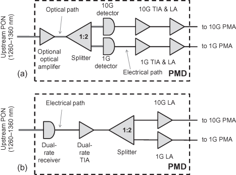
Option 1 has a much simpler electronic block, since both 1.25 Gbit/s and 10.3125 Gbit/s receivers can be optimized to provide maximum sensitivity for the respective signals. However, the extra 1 : 2 split used in the upstream channel introduces an extra loss of ≈3.5 dB, which deteriorates the signal power level at the receiver, degrading the BER and potentially breaking the power budget requirements. More stringent power budgets (e.g., PR20 or PR30) may become technically challenging to implement under such conditions, if at all possible.
Option 2, on the other hand, uses only a single optical module, though its photodetector and TIA unit must be dynamically adjusted to the data rate of the incoming signal, to prevent sensitivity deterioration resulting from incompatibility between signal data rate and receiver operating conditions. The electronic block must therefore switch rapidly between 1.25 Gbit/s and 10.3125 Gbit/s bursts. Such an operation is hard to achieve, because there is no available signal indicating what is the data rate of the next incoming burst, and thus data rate detection must be done on the fly.
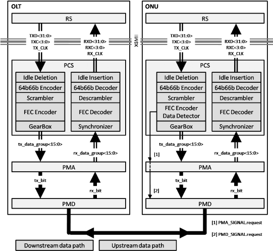
9.2.2 Physical Coding Sublayer (PCS)
The PCS sublayer is responsible mainly for converting the data stream received from xMII into codewords, which can then be passed through PMA and PMD and finally transmitted into the medium. In the receive path, PCS performs the reverse function, that is, it decodes the received data and recreates the original data stream. PCS houses such critical functionalities as data decoder/encoder, FEC encoder/decoder, Data Detector (ONU transmit path only), scrambler/descrambler, and gearbox, adjusting the data rates between PCS (bursty transmission) and PMA (continuous data stream).
Figure 9.3 shows the functionalities included in the PCS sublayer for the downstream and upstream data paths. In the upstream data path, the ONU uses the data detector located below the FEC encoder to drive the laser on and off, as described in Section 9.2.2.2.
Figure 9.3. Functional block diagram of the 10/10G-EPON PCS: Downstream and upstream data paths.
9.2.2.1 Idle Deletion.
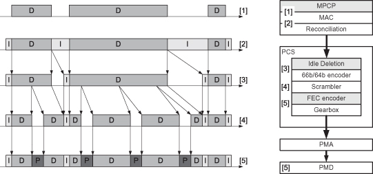
The Idle Deletion process in the 10G-EPON transmit path, implemented at the top of the PCS sublayer, is responsible for the removal of a number of excess IDLE characters, inserted by the MAC between subsequent frames. MACC enforces larger spacing between consecutive frames to prepare the data stream for insertion of the FEC parity at the PCS sublayer. At the output of the Idle Deletion function, the data stream is bursty and contains gaps, which will be used by the FEC encoder to insert calculated parity without increasing the PMD data rate. Effectively, the Idle Deletion process will delete 4 IDLE vectors of 72 bits (64 bits of data and 8 bits of control) for every 31 vectors of 72 bits received from the XGMII. Apart from deleting excess IDLE characters from the data stream, the Idle Deletion function must also guarantee that the minimum IPG is preserved between two subsequent Ethernet frames.
Operation of the Idle Deletion process, as well as the existence of gaps in the data stream at the output of the Idle Deletion process, are illustrated in Figure 9.4.
Figure 9.4. Transfer of data between the MACC and the output of the FEC encoder, when a data stream is ready for transmission. Special attention is paid to gaps in the data stream at the output of Idle Deletion process.
Due to the operation of the DIC as described in Clause 46.3.1.4 in IEEE 802.3-2008, the IPG may vary in size. DIC sometimes adds or deletes IDLE characters between subsequent frames, to ensure alignment of the /Start/ control character with the lane 0 on the XGMII interface. This introduces another variable to the already complex task of the MACC entity, attempting to calculate how much to delay the transmission of the next frame in order to allow the FEC encoder to insert calculated parity at the end of each codeword.
9.2.2.2 Data Detector.
In the upstream channel, a number of ONUs contend for accessing a single OLT interface, requiring a TDMA mechanism in place to negotiate access of individual subscriber stations. In order to avoid the so-called capture effect, where spontaneous noise generated by one or more ONU located close to the OLT could mask data transmission from more distant ONUs and prevent them effectively from delivering subscriber data, ONUs must switch their lasers off completely between transmissions. For that purpose, the ONU PCS was equipped with a Data Detector mechanism, which detects the presence of transmitted data and generates a laser control signal (setting the PMA_SIGNAL.request(tx_enable) primitive to ON or OFF, as necessary).
The Data Detector is designed in the form of a FIFO buffer, operating as a delay line and storing a sequence of codewords to be transmitted next toward the PHY. The 10G-EPON Data Detector is composed of an input process loading data into the FIFO buffer and an output process retrieving data from the FIFO buffer. In this way, both processes can operate in an asynchronous manner, as long as the input process does not allow for the FIFO buffer to be emptied by the output process.
Figure 9.5 shows the relationship between the condition of the Data Detector delay line and the generation of the laser control signal. The depth (or length) of the Data Detector is chosen in such a way that the introduced delay is sufficient to switch the laser on and transmit the necessary data burst elements:
- Synchronization pattern, which guarantees that the OLT burst-mode receiver has sufficient time to adjust its gain (Treceiver_settling) and synchronize its receive clock (TCDR).
- Burst Delimiter, a single 66-bit sequence that allows the OLT receiver to identify the beginning of the FEC protected data stream. Burst Delimiter is selected in such a way that the pattern can be reliably detected even in the presence of bit errors.
- A certain number (currently defined as 2) of IDLE characters, the first of which is used to synchronize the OLT data descrambler while the second one is used to provide the necessary initial IPG before the data stream can be fully synchronized.
Figure 9.5. Operation of the ONU Data Detector and resulting shape of a data burst. The FIFO depth in vertical and horizontal directions is not up to scale.
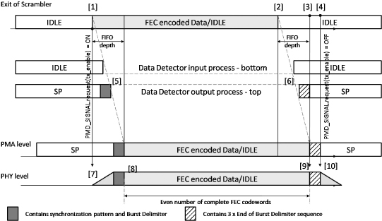
Operation of the data detector is relatively simple. At the start, the Data Detector FIFO buffer is filled with IDLE characters and the laser is disabled. Effectively, no data are transmitted into the PHY layer.
Upon arrival of the first data (non-IDLE) character (see point [1] in Figure 9.5), the Data Detector enables the laser by setting the PMA_SIGNAL.request(tx_enable) primitive to ON (point [7]). The laser takes a certain time to switch on, a period during which the MAC is transmitting IDLE characters, which in the Data Detector are replaced with SP sequence. After a complete series of SP pattern is transmitted (number of transmitted 66-bit blocks equal to SyncLength), the Data Detector output process at point [5] substitutes the last IDLE character by the Burst Delimiter sequence, which indicates the start of the FEC protected data stream—see point [8]. Data are delivered from the output of the scrambler until the last data character—see point [2]. Next, the FIFO buffer starts filling with IDLE characters, until it is completely full at point [3]. At that time, the Data Detector output process replaces three consecutive IDLE characters by the End of Burst delimiter pattern—see point [6]. The laser is still transmitting at this time. Only when the last of the End of Burst delimiter sequences is transmitted—see point [10]—the Data Detector sets the PMA_SIGNAL.request(tx_enable) primitive to OFF—see point [4]. This effectively starts switching the ONU laser off.
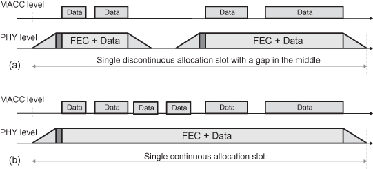
Longer sequences of IDLE characters can be received between data frames. However, if the FIFO buffer in the Data Detector is not emptied, the laser will not be switched off, though it is possible that, during a longer burst, the laser is switched off due to a very long run of IDLE characters. Such a situation (among others) is shown in Figure 9.6a. Note that the delay between the MACC and the PHY level, introduced by the Data Detector operation, was neglected to simplify the diagram.
Figure 9.6. Two possible layouts of the upstream allocation slot: (a) with a long run of IDLE characters causing laser to switch off in the middle and (b) a continuous upstream slot.
9.2.2.3 FEC in 10G-EPON.
All the 10.3125 Gbit/s links in the 10G-EPON architecture use stream-based FEC employing the Reed–Solomon code RS(255, 223). In 10/10G-EPON, this FEC code is used for both downstream and upstream links, while in 10/1G-EPON it is used only for the downstream link.
9.2.2.3.1 FEC Encoding Process.
The 64b/66b encoder produces a stream of 66-bit data blocks, 27 of which are aggregated at the FEC encoder to allow for generation of a single FEC codeword. Prior to FEC encoding, each of the said 66-bit bits data blocks is preprocessed by removing the redundant first bit from the sync header (bit [0]). This process does not impact data integrity because, for all data blocks, the bit [0] in the sync header is guaranteed to complement bit [1]. In this way, each 66-bit block is converted into a 65-bit block.
Twenty-seven of such truncated 65-bit data blocks provide in total 1755 bits, which is 29 bits short of the 223 bytes (1784 bits) required as input for the FEC encoder function for the RS(255,223) code. Therefore, 29 padding bits (each with binary value of 0) are prepended to the said 27 truncated 65-bit data blocks, forming the complete 223-byte payload portion of a FEC codeword. These data are then FEC-encoded, producing 32-byte bytes of FEC parity, which is used later on to form a complete FEC codeword. The 29-bit padding used during the FEC encoding process is discarded.
Next, the FEC encoder constructs the output codeword, comprising two components:
- Original 27 data blocks, each containing 66 bits (including the redundant bit [0] in the sync header), which were used to calculate the FEC parity.
- FEC parity, where each of the four data blocks of 64 bits obtained from the FEC encoder is prepended with a 2-bit sync header, resulting in a properly formed 66-bit block resembling a regular output word produced by the 64b/66b encoder. The FEC parity is distinguished from regular data blocks through the use of a specific sequence of sync headers. P802.3av TF selected 00 11 11 00 for this purpose; that is, the resulting FEC parity sequence looks like this: [00 P1] [11 P2] [11 P3] [00 P4], where P1 … P4 are subsequent 64-bit FEC parity blocks.
After this process is complete, the FEC encoder outputs 31 data blocks of 66 bits toward the PMA, and then it aggregates another sequence of 27 data blocks of 66 bits from the output of the scrambler.
9.2.2.3.2 FEC Decoding Process.
The 10G-EPON FEC decoder has the ability to correct or at least confirm the correctness of each of the 27 data blocks carried within an FEC codeword, based on the information carried within four FEC parity blocks of 66 bits each. The FEC code used in 10G-EPON is capable of correcting up to 16 errored symbols (a single symbol is 8 bits wide) per FEC codeword and detecting uncorrectable FEC codewords. Once this step is complete, the FEC decoder forwards the processed 66-bit data blocks to the descrambler and discards the parity blocks.
Additionally, the FEC decoder is also responsible for setting bit 0 of the sync header to the inverse of bit 1 of the sync header, thus making sure that the recovered bit stream is properly marked as data blocks.
9.2.2.3.3 Stream-Based FEC Versus Frame-Based FEC.
1G-EPON adopted optional frame-based FEC (used for all 10 Gb/s links), while 10G-EPON uses mandatory stream-based FEC. Both mechanisms are poised to provide extended protection against bit errors occurring during transmission in the optical channel. However, both are also quite different in many ways.
A stream-based FEC mechanism processes Ethernet frames and IDLEs as a stream of data symbols, resulting in a much simpler implementation, which is critical for high data-rate systems. This particular FEC-encoding method requires both transmitter and receiver communicating over a physical medium to use the very same framing structure. A device not supporting FEC encoding will not be able to retrieve data and separate it from parity. This means that all ONUs in an 10G-EPON must use FEC. In the stream-based method, the parity symbols generated after each data block are inserted immediately after the FEC parity codeword that they are protecting, resulting in an interleaving pattern of data blocks and parity blocks.
In the frame-based method, the parity symbols generated for each block are grouped together and are appended at the end of a frame. This leaves the data frame itself unaltered, representing a major advantage of this particular encoding method. Any device not supporting FEC encoding may still receive the data, though will not take advantage of the enhanced FEC bit protection. In 1G-EPON, adoption of this particular FEC coding method allows for mixing ONUs with enabled and disabled FEC on the same ODN.
9.2.3 Media-Independent Interface (GMII/XGMII)
An xMII (the first interface of this type was used in IEEE P802.3u Fast Ethernet and could operate at 100 MBd or 10 MBd) is a generic purpose interface connecting various types of PHYs to one and the same speed-agnostic MAC, through the RS sublayer. This means that a network device is capable of interacting with any type of underlying PHY over one and the same hardware interface, independently of the transmission medium this PHY is connected to. Effectively, the xMII interface shields the upper layers of the stack from having to interface with a plethora of different PHY types.
The success of the initial xMII included in P802.3u Fast Ethernet specifications led to the development of extended versions of this interface, capable of operating at gigabit data rates (GMII: 1 Gb/s MII) and then even 10 Gb/s data rates (XGMII: 10 Gb/s MII).
In terms of its physical structure, each xMII interface is composed of data lanes and control lanes. The number of data lanes and operating frequency predetermine the target data rate at which the xMII interface can transfer data:
- GMII (see Figure 9.7, as defined in Clause 35 of IEEE 802.3-2008) has a slightly different structure when compared with XGMII described below. It is composed of two 8-bit-wide data path, one 1-bit-wide clock path, and two 2-bit-wide control paths, the use of which depends on whether the transmit or the receive direction is considered. The transmit and receive data paths are unidirectional and independent, allowing for full duplex operation. In case of the transmit direction, TX_EN (transmit enable) and TX_ER (transmit error) signals are delivered. In case of the receive direction, RX_DV (receive data valid) and RX_ER (receive error) signals are delivered. Additionally, a 2-bit-wide data path is provided in the receiver direction, namely CRS (carrier sense) and COL (collision detected).
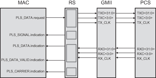
- In the case of XGMII (as defined in Clause 46 of IEEE 802.3-2008), this interface is composed of two 32-bit-wide data paths (capable of carrying 4 bytes of data at the same time with the clock rate of 312.5 MHz, providing an effective throughput of 10 Gb/s), two 4-bit-wide control paths (used to indicate whether data or control character is carried on the 8-bit-wide data path), and two 1-bit-wide clock paths. All the transmit and receive data paths are unidirectional and independent, allowing for full duplex operation. No Carrier Sense signal is transmitted through XGMII, and it may be generated only in the RS, if needed, as shown in Figure 9.8.
Figure 9.7. Internal structure of the GMII interface and interconnection between RS and PCS sublayers. MAC service primitives are also depicted for a complete picture of signal cross-relations.
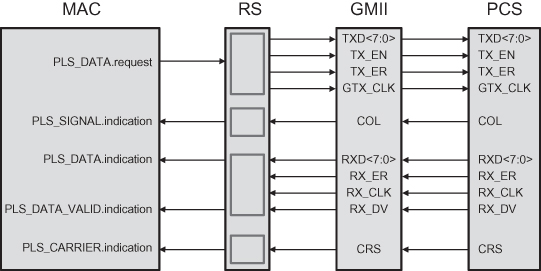
Figure 9.8. Internal structure of the XGMII interface and interconnection between RS and PCS sublayers. MAC service primitives are also depicted for a complete picture of signal cross-relations.
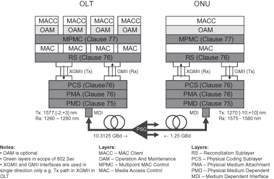
The symmetric 10/10G-EPON devices use exclusively the XGMII interface between RS and PCS sublayers, as shown in Figure 9.9, while the asymmetric 10/1G-EPON devices must have both XGMII and GMII interfaces implemented, as presented in Figure 9.10. A 10/1G-EPON OLT will have the transmit path from XGMII and the receive path from the GMII interface implemented, while at the 10/1G-ONU the situation is reversed; that is, there is only receive path from XGMII and transmit path from GMII interfaces. Such a mixed xMII interface use is only one of the examples of inventive steps that were taken during the development of the 10G-EPON system.
Figure 9.9. Symmetric, 10-Gbit/s-downstream and 10-Gbit/s-upstream EPON system architecture, with reference to specific clauses in IEEE 802.3av™-2009. Note: There can be more than one MAC interfaced with a single RS and a single MAC Control sublayer.
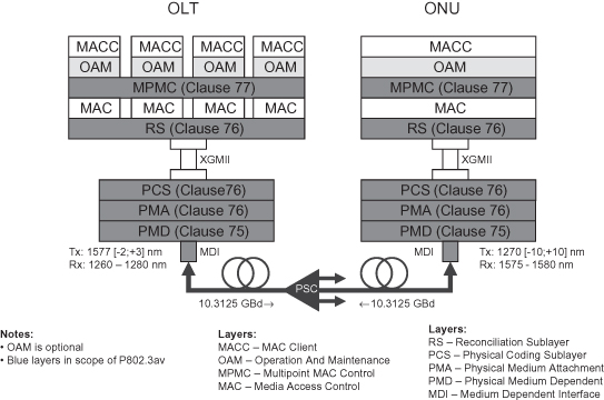
Figure 9.10. Asymmetric, 10-Gbit/s-downstream and 1-Gbit/s-upstream EPON system architecture, with reference to specific clauses in IEEE 802.3av™-2009. Note: There can be more than one MAC interfaced with a single RS and a single MAC Control sublayers.
9.2.4 Reconciliation Sublayer (RS)
The RS sublayer is primarily responsible for P2P emulation on top of the physical P2MP fiber plant. The general IEEE 802 architecture relies on the assumption that all Ethernet devices connected to the same physical media have the possibility of communicating directly, without the need of any extra network devices. Under this assumption, an Ethernet bridge will never forward a frame back to its ingress port.
This peculiar Ethernet bridge behavior brought concerns at the time 1G-EPON was under development, about whether the P2MP architecture can operate correctly under these conditions. Without a P2P emulation, the OLT would have a single MAC instance; thus effectively all ONUs would be connected to a single MAC at the OLT. In such a situation, a bridge placed in the OLT would never forward a frame received from an ONU to any other ONU on the same PON. This means that, physically, ONUs would require L3 connectivity in order to exchange data, which contradicts the requirement for L2 Ethernet connectivity between these devices.
Effectively, in order to overcome this problem, EPON systems require each downstream and upstream frame to be tagged with a network unique LLID, identifying the given target/source entity in an unambiguous manner. The number of LLIDs instantiated in a particular ONU has a significant impact on the system’s performance and is one of the most vital design choices for a fully functional EPON system with inherent tri-play support. Typically, two solutions are considered, namely one LLID per ONU or one LLID per queue (multiple LLIDs per ONU). Considering an ONU as a functional rather than physical entity, both LLID assignment policies remain compliant with the IEEE 802.3-2008 standard (see Clause 64.1.1). In the case of the latter approach, a single physical ONU (in the form of customer premises equipment) may have a number of virtual (logical) ONUs instantiated, each with a single LLID assigned to it. In order to ensure high QoS, the multiple LLID per ONU approach allows for traffic prioritization and better bandwidth management (polling) via the MPCP control plane.
To keep in line with the standard definitions and simultaneously assure that it is possible to support multiple LLIDs per ONU, system integrators and specifically EPON chip vendors typically develop chipsets capable of instantiating several logical (functional) ONUs per single physical ONU device. In this way, from an architectural point of view, a single optical port is connected to several ONUs. The OLT in this case recognizes each logical ONU in the physical ONU as an independent entity with only a single LLID. The RS includes two major functions related with P2P emulation on the P2MP environment, namely LLID insertion and LLID extraction coupled with LLID based filtering.
9.2.4.1 LLID Structure and LLID Subranges in 10G-EPON.
An LLID is composed of the mode bit (most significant bit) and logical_link_id partition, as defined in Clause 65.1.3.1 and reused in 10G-EPON. The mode bit was introduced to EPON architecture to guarantee compliance with shared LAN architecture, where a single station can communicate with any other station on the network segment. However, considering that access networks are completely different from corporate LANs in terms of data security and service models, very few of the existing EPON deployments actually utilize the mode bit. Its presence halves the range of available LLID addresses to 0x0000–0x7FFF, where 0x7FFF is reserved in 1G-EPON for broadcast transmissions and the range of 0x0000–0x7FFE can be used for unicast LLID assignment. In 10G-EPON, a new broadcast LLID was needed, and thus 0x7FFE was reserved for this purpose. Additionally, to ensure more future-proof definition of system specifications, a block of LLIDs was reserved for future use (0x7FFD–0x7F00 range). This leaves the range of 0x000–0x7EFF for unicast LLID assignment.
9.2.4.2 LLID Insertion Process.
The LLID insertion process is used in the transmit path of the P2MP extended RS sublayer, where each frame transmitted by the MAC layer toward the PHY layer is processed by inserting a number of EPON-specific extension fields, namely SLD and LLID. The original CRC8 calculated by the MAC entity is also replaced in this process. The SLD byte is inserted on position 3, while the LLID is inserted on positions 6 and 7, in an 8-byte-long preamble. Once the insertion of new fields is complete, the CRC8 is recalculated to guarantee integrity of such an extended preamble structure. Details of this process are described in Clause 76.2.6.1 of IEEE 802.3av™-2009 for 10G-EPON and in Clause 65.1.3.2 of IEEE 802.3-2008.
In terms of functionality, the LLID insertion process performs in exactly the same way in 1G-EPON and 10G-EPON, the only difference being the range of available LLIDs, as discussed in section 9.2.4.1. There is, however, a difference between the LLID insertion processes at the ONU and at the OLT.
In an ONU, a single MAC is connected via RS to the underlying PHY. This means that, in the 1 LLID per ONU environment, a frame leaving an ONU MAC can be tagged with one of two possible LLIDs: a broadcast LLID (either 0x7FFF, for 1.25 Gbit/s channel, or 0x7FFE, for 10.3125 Gbit/s channel) or a unicast LLID assigned to the ONU during the discovery process (following the registration handshake).
The situation is quite different on the OLT side, where a number of MAC instances (see Figure 9.9 or Figure 9.10) are connected via the RS sublayer to the underlying PHY. At any time, only one MAC is active and transmitting downstream. The LLID insertion process must therefore insert the LLID in the function of target ONU (unicast channel) assigned to it during the discovery and following registration processes, or insert a broadcast LLID (0x7FFE in 10G-EPON—assuming 10/1G-EPON or 10/10G-EPON OLT).
9.2.4.3 LLID Extraction Process and LLID-Based Routing.
In the receive data path, a frame received with the LLID in the preamble is passed through the RS sublayer, where the LLID tag is parsed and the routing information is extracted, reconstituting the original Ethernet preamble format. The extracted LLID is compared with the broadcast LLID as well as with the local unicast LLID assigned to the given ONU during the discovery and following registration processes. If the comparison criteria defined for 10G-EPON in Clause 76.2.6.1.3.2 are met, a frame is passed to the proper MAC (LLID-based routing) entity. Otherwise, a frame is dropped. This functionality is commonly referred to as LLID filtering, and it allows for logical isolation of subscriber channels transmitted over the P2MP shared media of the ODN plant.
The LLID routing function in ONUs is relatively simple, since all frames passing through the LLID filtering function are then directed to a single MAC. In the OLT, however, LLID routing is responsible for directing the filtered frame to one of multiple MAC instances connected to the RS.
Since the LLID insertion and LLID extraction functions are coupled for each data link, LLID tags exist only in the data path between two RS sublayers, and the MAC entities on the transmitting and receiving sides are not even aware of their existence. In this way, the MAC entities on both sides of the link are operating in the standard P2P manner, while the P2P emulation for P2MP environment is located in the RS sublayer.
9.2.4.4 Operation of the RS Sublayer with XGMII and GMII in a 10/1G-EPON.
As indicated before, in the case of a 10/1G-EPON device (both ONU and OLT) the RS sublayer is directly connected to two xMII interfaces types, namely XGMII and GMII. Such architecture is novel in IEEE PMD layers, and generated long discussions related with its technical feasibility as well as with the description to be included in the draft. Operation of the so-called dual rate Media-Independent Interface (drMII, acronym used only in this text) is described in Clause 76.2.2.
The 10/1G-EPON has to support different data rates in the transmit and receive paths, due to its inherent data rate asymmetry. In such a case, a combination of XGMII and GMII data paths is used for transmission and reception in a full duplex manner, while only specific halves of individual xMII interfaces are enabled at any time. This means that, at the 10/1G-EPON OLT, the transmit path in XGMII and the receive path in GMII interfaces are enabled. The situation is reversed in the 10/1G-EPON ONU, where the transmit path in GMII and the receive path in XGMII interfaces are enabled. For practical reasons, implementations are expected to include full GMII/XGMII interfaces (if implemented at all, i.e., some integrated chip designs do not need such structured interfaces at all), where unnecessary data paths are disabled. The mapping between XGMII/GMII service primitives and the PLS_DATA.request and PLS_DATA.indication (service primitives of the RS sublayer) is described in Clause 76.2.2.4. Figure 9.10 depicts the 10/1G-EPON architecture with drMII interface.
9.2.5 Media Access Control (MAC)
The Ethernet MAC specification describes a medium-independent entity responsible for a number of data delivery functions, including among others:
a. Data encapsulation (transmit path) and de-encapsulation (receive path), which has further a number of specific functions, that is:
i. Delimitation of frame boundaries, by adding framing information to the payload information provided by the upper layer MAC client entities, as well as frame synchronization.
ii. General-purpose address handling, by insertion of source and destination addresses in the transmit path as well as their paring in the receive path; this function is responsible for directing received frames to the proper MAC clients based on the target address, thereby providing selective frame routing.
iii. Error detection, based on the Frame Check Sequence field attached to the end of the assembled frame. The transmitting MAC attaches a CRC32 Frame Check Sequence to the end of the assembled frame, and the receiving MAC utilizes this sequence to guarantee data integrity and lack of bit errors.
b. Media Access Management, responsible for controlling media access and guaranteeing that a frame leaving the MAC service interface will be transmitted through PHY with a minimum delay. There are two very specific functions in this group, namely:
i. Medium allocation, which is responsible for controlling the time when the frame can be transmitted, by observing the current state of the underlying medium (collision avoidance).
ii. Contention resolution, which is responsible for handling data collision situations, when retransmission of the previous frame is necessary.
9.2.6 Multipoint MAC Control (MPMC)
The MAC Control (MACC) sublayer provides real-time control and manipulation of the MAC sublayer, allowing to customize operation and behavior of this PHY agnostic sublayer. Examples of MACC clients include the Bridge Relay Entity, LLC, or other applications characteristic of the particular IEEE network device. In the case of EPON, MACC entities include, for example, Discovery client, DBA client, and so on, and as such it is out of scope of the IEEE 802.3 standard to prescribe their exact behavior. However, MPMC provides a generic framework in the form of MPCP, providing a generalized mechanism for operation of MPMC clients. MPCP remains largely unchanged in 10G-EPON, as compared with 1G-EPON, and controls the discovery and registration processes as well as scheduling of the upstream bandwidth.
9.2.7 Extended Discovery Process in 10G-EPON
The Discovery process allows all previously inactive, deregistered, or powered-off ONUs to register in the EPON system, effectively gaining access to the shared upstream medium. This process is driven by the OLT Discovery agent, which periodically opens a discovery window in the upstream channel, during which no registered ONUs are allowed to transmit. During the same window, all unregistered ONUs are given the opportunity to announce their presence to the OLT by sending REGISTER_REQ MPCPDUs. The frequency of such discovery windows is not defined by the standard, and it depends only on implementation.
Due to the potential coexistence of the 1G-EPON, 10/1G-EPON, and 10/10G-EPON ONUs on the same ODN, the P802.3av TF found it necessary to extend the Discovery process defined currently in IEEE 802.3-2008, Clause 64. The principal requirement was to enable proper operation in the multi-rate environment, where a single OLT can support all three types of ONUs, with dual rate burst-mode transmission in the upstream channel. To ensure proper operation of the DBA clients located in the OLT and ONUs (out of scope of the standard), and utilizing a common time unit of TQ (equal to 16 ns), it is necessary to assure the existence of the following functionalities, which were added in IEEE 802.3av™-2009 to the Discovery Process previously used in 1G-EPON:
- Identification of the upstream/downstream channel data rate for a given target ONU. The information on the data rate used by the given ONU in the US channel is crucial, since the OLT DBA client must know in advance at what data rate the given ONU will be transmitting, to allocate the proper size of the transmission slot. Identification of the upstream channel data rate is based on the LLID address carried in REGISTER_REQ MPCPDU.
- Identification of the upstream channel ONU capabilities, determining whether the given ONU is 1G, 10G, or dual-rate-capable. Such information is required for proper registration of the particular types of ONUs, especially in the case of dual-rate-capable devices, which may choose to register in either 1G or 10G Discovery Windows opened by the OLT.
- Proper operation over two independent DS data channels (1G and 10G, separated using WDM) as well as over the TDMA shared, dual rate, upstream channel.
9.2.7.1.1 Initiation of Discovery Process at the OLT and ONU.
The Discovery process is initiated by the OLT discovery agent, resulting in the transmission of a discovery GATE MPCPDU, which carries such information as the starting time and length of the discovery window, together with the Discovery Information flag field, as defined in Clause 77.3.6.1. Individual flags contained in the Discovery Information field are used to notify all ONUs about the upstream and downstream channel transmission capabilities of the given OLT. This flag field is defined in such a way that the OLT can potentially support more than one data rate in each transmission direction, if such devices were deemed economically justified.
Upon receiving a broadcast Discovery GATE MPCPDU, ONUs parse it and retrieve information carried within. To ensure proper RTT measurement and time slot alignment, each ONU resets its local clock on reception of a downstream time-stamped MPCPDU. The Discovery GATE MPCPDU is an example of such a time-stamped MAC Control frame.
Next, an ONU with unregistered LLID(s) will wait for the start of the Discovery Window and then transmit upstream a REGISTER_REQ MPCPDU. Any other ONUs with unregistered LLID(s) will perform likewise, which means that during the Discovery Window multiple ONUs can access the PON medium simultaneously, potentially resulting in transmission overlap between data bursts from individual ONUs. The EPON system lowers the probability of burst overlap by operating a contention algorithm at all the ONUs, where each ONU waits a random amount of time (typically shorter than the length of the Discovery Window itself) before transmitting the REGISTER_REQ MPCPDU. The length of such an additional delay time is randomly selected for each ONU, resulting in a Random Delay Mechanism. In this way, if the Random Delay Mechanism is successful, the OLT can receive multiple valid REGISTER_REQ MPCPDUs during a single Discovery Window.
Each REGISTER_REQ MPCPDU delivers two pieces of vital information about the source ONU, namely its MAC address and the depth of the grant queue, which in turns defines how many grants can be assigned to the given ONU in advance. Additionally, it also carries the Discovery Information field, characterizing transmission capabilities of the given ONU in the upstream and downstream channels, as specified in Clause 77.3.6.3. Moreover, in order to optimize upstream channel utilization and minimize the size of guard bands between data bursts from individual ONUs, the REGISTER_REQ MPCPDU also carries laser on/off parameters, providing the OLT with information about the quality of ONU hardware.
9.2.7.1.2 Initial ONU Registration at the OLT.
After successful reception of a REGISTER_REQ MPCPDU, the OLT has sufficient information to start the registration process. A new LLID is created at the OLT and associated with the MAC address of the registering ONU. As a follow-up, the OLT transmits downstream a unicast REGISTER MPCPDU to the newly discovered ONU (MAC unicast channel, with broadcast LLID since the ONU does not have an associated LLID at this moment). This message carries the newly assigned LLID as well as information on the synchronization time required by the OLT. For confirmation purposes, the OLT echoes the maximum number of pending grants (though the purpose of this echo is not defined in the standard). The OLT also transmits the target laser on/off parameter values, which are to be used by the ONU during the following operation. It is assumed that the parameter values transmitted by the OLT may be different than what the ONU indicated in the REGISTER_REQ MPCPDU, though they must not be smaller than the ONU advertised values, which would prevent the ONU from proper operation.
9.2.7.1.3 ONU Confirmation Scheduling.
Once the REGISTER MPCPDU is transmitted and the LLID association is created at the OLT side, the OLT has sufficient information to allow the given ONU to access the PON medium. The DBA Client operating at the OLT side selects the upstream channel transmission window and schedules it by sending downstream a (LLID) unicast message to the ONU in the form of a GATE MPCPDU.
The transmission slot carried in this GATE MPCPDU will allow the registering ONU to transmit upstream a REGISTER_ACK MPCPDU and thus complete successfully the registration process. After this stage, the ONU is considered as completely activated and bidirectional traffic flow may commence.
9.2.7.1.4 Repeated ONU Registration.
Under certain circumstances (e.g., excessive BER, problems with bidirectional connectivity, timeout, signal loss, etc.), an ONU must go through repeated discovery and registration processes, trying to remedy the existing connectivity problems. Additionally, there may be also situations where an ONU needs to inform the OLT of its desire to deregister, due to (for example) a request from higher management layers.
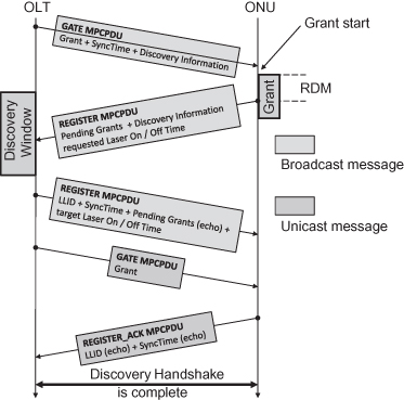
In the first case, the OLT may request the ONU to deregister by sending a REGISTER MPCPDU to this particular ONU with the Deregister flag enabled. In the latter case, an ONU may deregister by sending upstream a REGISTER_REQ MPCPDU with the Deregister flag set, indicating that the OLT should release the LLID association for the given MAC address and allow the given ONU to go through the discovery and registration processes once more, as presented in Figure 9.11.
Figure 9.11. Exchange of MPCPDUs during the Discovery Handshake process.
9.2.7.2 Changes to MPCPDUs.
In order to support dual-rate operation, as well as optimize the use of the upstream channel by allowing laser on/off time negotiation between ONU and OLT, several changes to the MPCPDUs were introduced in IEEE 802.3av™-2009.
9.2.7.2.1 GATE MPCPDU.
The regular granting GATE MPCPDU was not changed and maintains its internal structure, as defined in Clause 64 for 1G-EPON (see also Clause 77.3.6.1 in IEEE 802.3av™-2009). The Discovery GATE MPCPDU was, however, subject to some changes (see Figure 9.12).
Figure 9.12. Internal structure of the GATE MPCPDU in (a) granting and (b) Discovery versions.
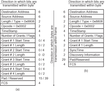
The most visible change in the GATE MPCPDU structure is the addition of the Discovery Information field, which contains information on the OLT transmission capabilities for both downstream and upstream channels. This field was deliberately defined with 16 bits, to allow for future extensions of this message and the scope of information carried in this field, without the need to redefine the message itself. The internal structure of the Discovery Information field is presented in Table 9.3.
TABLE 9.3. Internal Structure of the Discovery Information Field in the GATE MPCPDU
| Bit | Field Name | Description / Values |
| 0 | 1.25 Gbit/s upstream OLT capability | 0—No 1—Yes |
| 1 | 10.3125 Gbit/s upstream OLT capability | 0—No 1—Yes |
| 2–3 | Reserved/undefined | Ignored upon reception |
| 4 | OLT opens 1.25-Gbit/s Discovery Window | 0—No 1—Yes |
| 5 | OLT opens 10.3125 Gbit/s Discovery Window | 0—No 1—Yes |
| 6–15 | Reserved/undefined | Ignored upon reception |
Additionally, there are minor changes in the definition of the “Grant #n Length” field, which is still expressed in TQ units but must account for all necessary elements of transmission overhead, namely laserOnTime, syncTime, laserOffTime, BURST_DELIMITER, two initial IDLE blocks, FEC parity overhead, and burst terminator sequence (composed of three END_BURST_DELIMITER blocks), which consume part of the allocated bandwidth slot.
9.2.7.2.2 REGISTER_REQ MPCPDU.
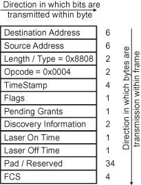
REGISTER_REQ MPCPDU suffered changes in its internal structure (see Figure 9.13), due to the addition of a number of new data fields, namely Discovery Information, Laser On Time, and Laser Off Time.
Figure 9.13. Internal structure of the modified REGISTER_REQ MPCPDU.
The Discovery Information field (see its internal structure in Table 9.4) is a counterpart of the field with the same name added to the Discovery GATE MPCPDU. It has a similar function; that is, it indicates the transceiver data rate capability in the transmit and receive paths, though this time for the ONU rather than for the OLT. The current definition of this field ensures its future extensibility to higher data rates, as well as transmission of any other necessary information related with the ONU downstream/upstream capabilities, which are currently not covered in the standard.
TABLE 9.4. Internal Structure of the Discovery Information Field in the REGISTER_REQ MPCPDU
| Bit | Field Name | Description / Values |
| 0 | 1.25 Gbit/s upstream ONU capability | 0—No 1—Yes |
| 1 | 10.3125 Gbit/s upstream ONU capability | 0—No 1—Yes |
| 2–3 | Reserved/undefined | Ignored upon reception |
| 4 | ONU attempts registration in 1.25 Gbit/s Discovery Window | 0—No 1—Yes |
| 5 | ONU attempts registration in 10.3125 Gbit/s Discovery Window | 0—No 1—Yes |
| 6–15 | Reserved/undefined | Ignored upon reception |
The addition of the Laser On/Off Time fields to the REGISTER_REQ MPCPDU was dictated by the necessary optimization of the upstream channel utilization, where the large 512 ns laser on/off period length defined in 1G-EPON standard was deemed excessive for 10G-EPON. Initial deployments relied on laser drivers designed for P2P links, which required such long on/off times. The introduction of dedicated BM laser drivers and constant improvements in their design brought the on/off times for current generation of 1.25 Gbit/s lasers down to the level of several dozen nanoseconds. It is expected that 10.3125-Gbit/s lasers will not exhibit worse performance figures in this field. Furthermore, to eliminate once and for all a static allocation of the laser on/off times, the P802.3av TF decided to allow for negotiated guard band size, where an ONU would indicate the minimum value of the laser on/off period it is capable to support and the OLT would adjust the value (upwards only) to simplify the DBA operation and use the same laser on/off times for all ONUs, independently from the manufacturer. Note that the laser on/off period value was capped at 512 ns, which was considered as the maximum necessary value, even with very low quality laser drivers.
The Laser On Time/Laser Off Time field has the form of an 8-bit-wide field, where the value of the laser on/off time is expressed in TQ units. This allows for simple coverage of the complete 0- to 512-ns range (with 16-ns increments) in a single 8-bit value.
9.2.7.2.3 REGISTER MPCPDU.
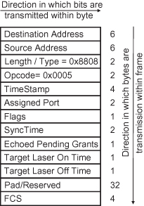
The REGISTER MPCPDU has changes complementary (see Figure 9.14) to those of the REGISTER_REQ MPCPDU, representing feedback received from the OLT in response to the registration request transmitted during the Discovery Window. As such, the REGISTER MPCPDU (as compared to Clause 64 for 1G-EPON) was added only two new data fields, namely Laser On Time and Laser Off Time. Definition and internal structure of these two fields is identical to those included in the REGISTER_REQ MPCPDU, and thus further elaboration is not deemed necessary.
Figure 9.14. Internal structure of the modified REGISTER MPCPDU.
However, it is worth noting a slightly different interpretation of these two fields when compared with the REGISTER_REQ MPCPDU laser on/off time parameters. In case of the REGISTER_REQ MPCPDU, the ONU would indicate what minimum laser on/off period length can be supported by the existing transceiver. Therefore, this defines the minimum length of the interburst gap. The OLT, once the laser on/off period length characteristic for the given ONU is received during the registration process, may decide to increase these values to any value higher than the value indicated by the ONU, while taking into consideration that neither of these two parameters can exceed 512 ns. Next, the value of laser on/off time selected by the OLT is transmitted downstream, for the ONU to comply with. The ONU adjusts the depth of its Data Detector in the PCS to accommodate the changes requested by the OLT. Note also that, physically, ONU lasers may switch on/off faster, though the size of the guard band is still defined by the depth of the Data Detector in the PCS.
9.2.7.2.4 Other MPCPDUs.
Other MPCPDUs, namely REPORT and REGISTER_ACK, were not modified in IEEE 802.3av™-2009, apart from minor editorial changes targeting clarification of the already existing specifications as well as elimination of any doubts, which the P802.3av TF had during the balloting stage.
9.2.7.3 Impact of Stream FEC on Operation of the MPCP Sublayer.
10G-EPON operates with mandatory FEC for all 10.3125-Gbit/s links. This means that part of the usable bandwidth is occupied by parity code, which increases the robustness of the data channel to bit errors, providing the means for achieving the target BER = 10−12 which would be impossible otherwise, considering the loss in receiver sensitivity due to the increase of the transmission data rate.
For this reason, transmission in 10G-EPON is substantially different from that in 1G-EPON, where FEC was frame-based rather than stream-based. On one hand, in 1G-EPON a station with no FEC support could still delineate data and try to receive it without using FEC gain. This is not possible in 10G-EPON, since data and FEC parity are interleaved. On the other hand, parity insertion at the PCS requires additional space between the frames to maintain a constant data rate at the PHY interface. This means that the MAC data rate and the PCS data rate must meet exactly the ratio of 223/255, corresponding to the FEC RS code designation; that is, 255 bytes of data are transmitted at PCS layer, containing only 223 bytes of subscriber data and 32 bytes of FEC parity. Effectively, data transmitted from the MACC toward the PHY, through the MAC, must have a larger IPG between individual frames, sufficient in size to accommodate the FEC parity later on (see Figure 9.4).
This means that the MACC must ensure that a sufficient IPG is left between consecutive frames, to allow the Idle Deletion process in the upper PCS to remove the extra IDLE characters and separate the given frame (including necessary IDLE characters) into FEC codewords, each of which is then extended with FEC parity. This new functionality required substantial changes in the definition of the FEC_Overhead and CheckGrantSize functions, which have to estimate the quantity of extra IDLE characters to be inserted after the end of the given frame. To fully appreciate the complexity of the problem, consider that the MACC does not know in what condition the PCS-based FEC encoder is and where the given FEC codeword boundary is located. It does not know exactly how many IDLE characters will be deleted in PCS (see Figure 9.4).
If too many IDLEs are inserted, part of the useful bandwidth will be wasted. On the other hand, if too few IDLEs are inserted, data will be overwritten in the FEC encoder, resulting in data loss. The P802.3av TF took therefore a number of meetings to arrive at the solution, in which the MACC can track (very) precisely the location and quantity of FEC parity which is inserted at the PCS sublayer. That means that the quantity of inserted IDLEs can be calculated precisely, optimizing the bandwidth utilization especially in the upstream channel.
9.3 COEXISTENCE OF 1G-EPON AND 10G-EPON
The gradual evolution toward 10G-EPON systems requires replacement of the minimum amount of active equipment up-front, leaving the underlying fiber infrastructure intact. In this way, Service Providers can have a rare opportunity of maximizing the ROI for the systems they already heavily invested in when deploying 1G-EPON. Simultaneously, introduction of next-generation equipment into the network structure allows for delivering more bandwidth demanding services to (premium) customers willing to pay a slightly higher connection cost per port, representing early adopters of higher capacity 10G-EPONs. Thus, it comes as no surprise that the issues related to the coexistence with the legacy equipment on the same PON plant have been considered critical from the very beginning of the project, warranting the investigation of the wavelength allocation schemes, dual rate operation, and the necessary changes to the MPCP framework resulting from coexistence of various data rate devices in the same infrastructure.
9.3.1 Downstream Channel
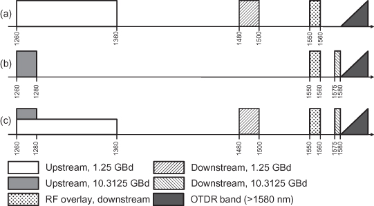
Due to the requirement of complete backward compatibility, in 10G-EPON the downstream 10.3125-Gbit/s and 1.25-Gbit/s channels will be WDM multiplexed, thus creating in effect two independent P2MP domains. The guard band between data channels ought to be sufficiently large to allow for their uninterrupted operation under any temperature conditions provided for in the technical specifications of the emerging hardware. The 1.25-Gbit/s downstream link will therefore remain centered at 1490 [±10] nm (in accordance with the IEEE 802.3-2008 standard, Clause 60), while the new 10.3125-Gbit/s downstream link is centered around 1577 [+3, −2] nm, creating a significantly narrower band, limited at the lower end by the RF video overlay and by the OTDR filter cutoff band at the upper end (see Figure 9.15). After long debates, the P802.3av TF agreed on aligning all power classes in terms of wavelength allocation, allowing optical subassembly vendors to develop a single ONU optical filter design. A comparison of 10G-EPON and 1G-EPON wavelength allocation plans is depicted in Figure 9.15.
Figure 9.15. Wavelength allocation plan for (a) 1G-EPON, (b) 10G-EPON, and (c) combined, 1G-EPON and 10G-EPON. All options account for the RF video overlay and OTDR service bands.
9.3.2 Upstream Channel
The upstream channel in any PON system is always considered technically critical, mainly because of the need to balance technical complexity and cost of the resulting ONU hardware. In the case of 10G-EPON, WDM multiplexing for 10.3125-Gbit/s and 1.25-Gbit/s channels in the upstream is discouraged, mainly because of lack of available wavelength bands. The minimum dispersion window (around 1310 nm) is already in use by 1G-EPON, thus leaving apparently no space for introduction of a new, 10.3125-Gbit/s channel, as shown in Figure 9.15.
Accepting the fact that existing 1G-EPON specifications must not be modified in any way, causing potentially some of the deployed equipment to become standard incompliant, only dual rate burst-mode multiplexing remains as a viable option. Therefore, both 10.3125-Gbit/s and 1.25-Gbit/s upstream transmissions will partially overlap in frequency domain (though remain separated in time domain via TDMA), with the 1G-EPON ONUs remaining centered at 1310 [±50] nm, while the 10G-EPON ONUs will transmit at 1270 [±10] nm, taking advantage of the fact that only narrower-band DFB LDs must be used at 10.3125 rates [9], which are inherently more narrowband. In this way, the upstream transmission will become not only bursty but also dual-rate, representing a new level of technical complexity for the OLT receiver.
In such a system configuration, the OLT receiver will have to be equipped with a set of new functionalities. The AGC required for burst-mode reception, currently considered as a state-of-the-art technical achievement, will be surpassed by a dual-rate burst-mode device. Such a component will have not only to ensure proper power level adjustment, but also identify the incoming data rate and perform receiver adjustment in order to maximize its sensitivity for each particular burst.
However, developing an OLT dual rate burst-mode receiver and implementing it in accordance with the IEEE specifications may prove to be a nontrivial task, requiring significant research to be conducted by electronics and receiver manufacturers. Initial prototypes of such dual-rate burst-mode receivers were already presented publicly, though their commercial availability remains at this time undefined.
9.4 TARGET APPLICATIONS FOR 10G-EPON SYSTEMS
Given the virtually constant increase in bandwidth requirements from end-subscribers as well as changes in commonly utilized networked services, 1G-EPON networks will soon (some estimate that in the next 3–5 years) become inadequate to support the next generation of multimedia rich digital contents. When it was first introduced, 1G-EPON represented a substantial step in the evolution of access networking, creating a platform for delivery of bandwidth intensive applications like IPTV or VoIP. Now, a few years later, users started looking at more bandwidth demanding applications, like HD-IPTV, Picture in Picture (PiP) TV, cloud applications, and so on, which will again cause a bottleneck in access networks if transition to a higher-capacity platform is not carried out. 10G-EPON is therefore right on time to meet growing customer expectations.
High-definition, video-centric, multimedia-rich services are on the rise, fueled by several years of increased popularity of HDTV sets and their increased penetration in typical households. Other rapidly growing applications for high-capacity access networks include video-conferencing, interactive video, online interactive gaming, peer-to-peer networking, karaoke-on-demand, IP video surveillance, and so on. Cloud computing, storage area networks, and remote storage are some of the applications that evolved thanks to increase in the capacity of the access loop. Even such applications as VoIP, typically generating rather small data streams, tend to contribute to the bandwidth demand mostly due to the high number of subscribers. Consider here that in 2006 we had approximately 35 million VoIP users worldwide, which is expected to grow to anywhere between 120 and 150 million by 2011.
10G-EPON was also designed with other two target applications in mind. The MDU market is the first of them, focusing on residential areas with high population density, where a large fraction of home/apartment owners also subscribe to digital services. Such markets exist mainly in certain regions of Europe, as well as in Asia. MDU development is not very popular in the United States, and thus this application does not fit the needs of the American market. The 10G-EPON is also naturally suited for deployment in such areas as hospitals, schools, and business campuses, as well as governmental and educational institutions, where a large number of wired/wireless users generate a substantial quantity of data traffic which then needs to be delivered to aggregation networks. Currently existing solutions based on DSL access are simply not future-proof, given the constant increase in the number of connected computers, PDAs, and other equipment with data interfaces.
The last target application considered at the time of conception of the 10G-EPON SG was mobile backhauling, which has received recently substantial attention due to the ongoing transition to 3G and 4G mobile networks. Base stations implementing these new standards provide subscribers with substantially more bandwidth than 2G devices, which again puts more stress on the data uplink to the nearest aggregation point. Existing ATM solutions are already limiting data rates provided for 2G devices, not to mention newer base stations or even wireless access points operating under IEEE 802.11b/g/n or 802.16. Such access points must be connected to high-capacity backhaul links, typically with symmetric transmission capacity. The 10G-EPON fits perfectly this application, and the first 10G-EPON ONUs integrated into Base Station devices are expected by the end of 2009.
Last but not least, the 10G-EPON can find its applications anywhere the 1G-EPON was once so successful, providing higher transport capacity and lower cost per subscriber and, ultimately, providing subscribers with more choices for their digital entertainment. Initial deployment plans for 10G-EPON systems indeed target overbuilt existing 1G-EPON networks, by migrating at least a fraction of premium subscribers to newer equipment. Recent announcements of first demonstration versions of 10G-EPON equipment [10, 11] proves also continued support for this technology among equipment vendors.
9.5 CONCLUSIONS
It is expected that 10G-EPON equipment will follow the path of 10-fold capacity increase at three times the port price, so characteristic of all Ethernet equipment: Some of the technical challenges the new system will be faced with include (a) backward compatibility with legacy EPONs (including RF video overlay) and (b) support for asymmetric data rates (10 Gb/s downstream and 1 Gb/s upstream). PHY layer challenges include, among others, (a) dispersion penalties and decreased receiver sensitivity due to the 10-fold increase of the data rate, (b) nonlinear effects in the fiber plant (ODN) due to high launch powers in 29-dB ChIL compatible PMDs, and (c) inherent jitter and clocking problems due to dual rate operation.
Dual-rate MAC stack and dual-rate burst-mode reception represents the next level of technical complexity, but were resolved by Q1 2010 with successful demonstration of commercial dual-rate OLTs. The economic feasibility of dual-rate EPONs is currently questionable from a practical standpoint, though overbuild (brown-field) scenarios can potentially benefit from such a solution, providing extended ROI on relatively new 1G-EPON equipment.
The development process of 10G-EPONs will keep on driving state-of-the-art engineering in the area of burst-mode receivers, high-power laser sources, and ultrasensitive high-data-rate photodetectors. Chip integration as well as protocol implementation will also present several challenges yet to be surmounted, mainly in the form of a reliable Discovery Process, data rate negotiation, and so on.
It is also anticipated that the rapid stabilization of 10G-EPON PMD parameters may benefit cooperation between FSAN/ITU-T and IEEE PON groups, resulting in convergence of 10G-EPON and Next-Generation PON (NG-PON) systems for some of power budgets, at least at the PHY level. This will allow hardware manufacturers to achieve higher production volumes and cut equipment costs, making both PON systems far more economically attractive than when considered separately.
ACKNOWLEDGMENTS
The authors would like to thank Glen Kramer for a careful review and many insightful comments.
REFERENCES
1. G. Kramer, Ethernet Passive Optical Networks, 1st edition, Communications Engineering Series, McGraw-Hill Professional, New York, 2005.
2. G. Kramer and G. Pesavento, EPON: Challenges in building a next generation access network, in 1st International Workshop on Community Networks and FTTH/P/x, Dallas, 2003, pp. 66–73.
3. A. Kasim, P. Adhikari, N. Chen, N. Finn, N. Ghani, M. Hajduczenia, P. Havala, G. Heron, M. Howard, L. Martini, R. Metcalfe, M. O’Connor, M. Squire, W. Szeto, and G. White, Delivering Carrier Ethernet: Extending Ethernet Beyond the LAN, 1 edition, McGraw-Hill Osborne Media, New York, 2007.
4. G. Kramer, What is next for Ethernet PON?, in 5th International Conference on Optical Internet (COIN 2006), Jeju, South Korea, 2006.
5. S. Swanson, Ethernet standards evolve to meet high-bandwidth networking needs, Lightwave, Vol. 12, 2006. Available at http://www.lightwaveonline.com/about-us/lightwave-issue-archives/issue/ethernet-standards-evolve-to-meet-high-bandwidth-networking-needs-53434312.html.
6. H. Steenman, End User Perspective on Higher Speed Ethernet, AMS-IX, online report, available at: http://www.ieee802.org/3/hssg/public/sep06/steenman_01_0906.pdf, 2006.
7. Teknovus Ltd., Teknovus and Fiberxon Cooperate on “Turbo” EPON, Teknovus Press Release, available online at http://teknovus.com/Page.cfm?PageID=140&CategoryID=14, 2007.
8. IEEE 802.3, Call For Interest: 10 Gbps PHY for EPON, online report, available at http://www.ieee802.org/3/cfi/0306_1/cfi_0306_1.pdf, 2006.
9. IEEE 802.3av TF, “Baseline Proposals,” electronic report, available at http://www.ieee802.org/3/av/public/baseline.html, 2007.
10. fibresystems.org, ZTE unveils world’s first next-generation PON equipment, fibresystems.org, online article, available for download at http://fibresystems.org/cws/article/newsfeed/36940, 03.12.2008.
11. Lightwave, Teknovus to demo 10G EPON at FOE, Lightwave, online article, available for download at: http://lw.pennnet.com/Articles/Article_Display.cfm?Section=ARTCL&SubSection=Display&PUBLICATION_ID=13&ARTICLE_ID=350716&pc=ENL, 19.01.2009.