
10
BROADBAND POWER-LINE COMMUNICATIONS
10.1 INTRODUCTION
The idea of using power lines also for communication purposes was already around at the beginning of the last century [1, 2]. It is now broadly referred to as power line communications (PLC). The obvious advantage is the widespread availability of electrical infrastructure, so that theoretically deployment costs are confined to connecting modems to the existing electrical grid.
Today, applications include the provisioning of Internet to end customers, referred to as Access PLC, or broadband over power line (BPL) [3, 4]. Besides, PLC technology is successfully being used for the distribution of audio, video, voice, and data services within the users’ homes, also referred to as In-Home PLC. Furthermore, utility companies are becoming more and more interested in automatic meter reading infrastructure (AMI) and smart grid, allowing a more efficient electrical network management [5–7].
Early PLC systems made use of narrow bandwidths on high-voltage lines. The operating frequency range went up to a couple of hundred kilohertz, and data rates were on the order of hundreds of bits per second (bit/s) [1, 2]. Up to the present day, narrowband power-line systems are in operation mainly for control services that require data rates below 2 Mbit/s. Popular narrowband PLC systems are, for example, X10, KNX, INSTEON, BACnet, and LonWorks. However, they are not at the focus of this contribution. More on past and present narrowband PLC systems may be found in references 8 and 9.
In line with the advances of digital communications in general, also PLC systems were able to enormously boost their data rates. In the last decade, PLC chips by semiconductor vendors, such as Intellon [10], and DS2 [11], came to market that operate in the band from around 1 to 30 MHz. The chips are mainly based on two consortia-backed specifications developed within the frameworks of the HomePlug Powerline Alliance (HomePlug) [12] and the Universal Powerline Association (UPA) [13]. The HomePlug specification comes in two main releases, HomePlug 1.0 and its evolution HomePlug AV, with physical layer (PHY) peak data rates of 14 Mbit/s, and 200 Mbit/s, respectively [14–20]. Both releases target the In-Home market. An Access specification called HomePlug Access BPL is currently under development. The rivaling UPA specification was selected by the European Union IST research project OPERA as baseline technology [21] and provides an Access as well as an In-Home solution. The In-Home solution, called Digital Home Standard (DHS), has a peak PHY data rate of 240 Mbit/s, while the Access solution provides at best 205 Mbit/s [22–25]. More recently, a third specification named High-Definition Power Line Communications (HD-PLC), a trademark of Panasonic [26] that is promoted within the HD-PLC Alliance, was released. It is designed to distribute multimedia content In-Home and has a theoretical PHY peak data rate of 210 Mbit/s [27].
Departing from all these specifications, continuous research and development efforts have led to “next-generation” prototypes, enabling data rates in excess of 400 Mbit/s [11, 28]. Besides advances in digital signal processing, these systems also owe their throughput boosts to an increased spectrum usage, ranging from 1 MHz up to around 200 MHz. With the ability to fulfill additionally high Quality of Service (QoS) and coverage expectations, it becomes clear that PLC can, in some cases, be not only a complement, but even a superior alternative to state-of-the-art wire line as well as wireless systems like xDSL, Wi-Fi, WiMAX, UMTS/HSPA and CDMA2000 EV-DV [29].
Nevertheless, to make PLC systems an even broader success, an internationally adopted PLC standard is essential. The International Telecommunications Union (ITU), as well as the Institute of Electrical and Electronics Engineers (IEEE) commenced work on such next-generation standards, namely ITU-T G.hn and IEEE P1901. ITU-T G.hn focuses on home networking and smart grid applications and has recently been identified by the U.S. National Institute of Standards and Technology (NIST) as an important standard for smart grid interoperability [30]. ITU-T G.hn is applicable not only to power lines but also to phone lines and coaxial cables, thus for the first time defining a single standard for all major wire line communications media. At the end of 2008, the PHY layer and the overall architecture were consented in ITU-T Recommendation G.9960 [31]. In the same year, the HomeGrid Forum was founded to promote the ITU-T G.hn standard and to address certification and interoperability issues [32]. In parallel the IEEE P1901 is working on the “Draft Standard for Broadband over Power Line Networks: Medium Access Control and Physical Layer Specifications.” It will cover the aspects Access and In-Home, as well as coexistence of Access-In-Home and In-Home-In-Home networks [33]. However, to get sufficient industry support, the IEEE P1901 standard might have included two incompatible PHY and medium access control (MAC) substandards. They are based on HD-PLC and HomePlug AV. This inherent fragmentation of IEEE P1901 makes some analysts believe that ITU-T G.hn will emerge as the dominant next-generation solution [34, 35].
All PLC-systems have to tackle the problem of PLC-generated interference, also referred to as electromagnetic compatibility (EMC). The problem has been addressed by limiting the used power spectral density (PSD), as well as adaptively notching selected frequencies that are in use, for example, by Amateur Radio or television broadcasting services. However, achievable PLC data rates are primarily related to the available signal-to-noise ratio (SNR) over a certain frequency range. With a cap on the PSD, the remaining outer factors in the struggle for higher PHY data rates are the attenuation imposed by the power-line channel, as well as noise at the receiver side.
Issues of EMC, channel, and noise characteristics, as well as the expected mean SNR, are dealt with in Sections 10.3 to Section 10.6, respectively. In the sequel, Section 10.7 provides a PHY- and MAC-centered overview of the current specifications HomePlug AV, UPA (Access and DHS), and the prospective international ITU-T G.hn standard. First, however, different PLC deployment scenarios are introduced in Section 10.2.
10.2 POWER-LINE SCENARIOS
Power-line communications can make use of high-voltage, medium-voltage, and low-voltage grids as shown in Figure 10.1.
High-voltage (HV) lines, with voltages in the range from 110 kV to 380 kV, are used for nationwide power distribution and consist of long overhead lines with little or no branches. Theoretically, these lines could be used for communication purposes. However, their potential for broadband power-line services is limited. High-voltage arcing noise is a problem, and signal attenuation in decibels increases approximately linearly with distance. Furthermore, fiber-optic backhaul networks are frequently running alongside HV lines, providing a more attractive communication alternative [4].
Medium-voltage (MV) lines, with voltages in the range from 10 kV to 30 kV, are connected to the HV lines via primary transformer substations. The MV lines are used for power distribution between cities, towns, and larger industrial customers. They can be realized as overhead or underground lines. Furthermore, they exhibit a low level of branches. From a communications point of view, their potential to serve as backhaul for Access networks, especially in rural areas, is much higher than that of HV lines.
Low-voltage (LV) lines, with voltages in the range from 110 V to 400 V, are connected to the MV lines via secondary transformer substations. A communication signal on an MV line can pass through the secondary transformer onto the LV line, but with a heavy attenuation on the order of 55–75 dB [36]. Hence, a special coupling device or a PLC repeater are required if one wants to establish a communications path. As indicated in Figure 10.1, the LV lines lead directly or over street cabinets to the end customers’ premises. LV lines are therefore at the heart of the power-line Access network. Note that considerable regional topology difference exits. For example, in the United States, one smaller secondary transformer on a utility pole might service a single house or a small number of houses. In Europe, however, it is more common that up to 100 households get served from a single secondary transformer substation. Furthermore, as pointed out in reference 37, significant differences exist between building types. They may be categorized as multi-flat buildings with riser, multi-flat buildings with common meter room, single-family houses, and high-rise buildings. Their different electrical wiring topologies influence signal attenuation as well as interference between neighboring PLC networks [38]. In most cases the electrical grid enters the customers’ premises over a house access point (HAP) followed by an electric meter (M) and a distribution board (fuse box). From the distribution board the LV lines run up to the different power sockets in every room.
Figure 10.1. Power-line deployment scenarios.
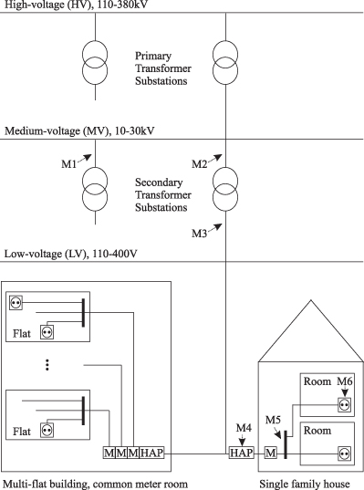
Besides the depicted Access and In-Home scenarios, there are cases of PLC deployments within vehicles such as cars, trucks, ships, airplanes, or even space crafts. However, such In-Vehicle PLC is not the focus of this chapter. Instead, the interested reader may refer to references 39–41 and references therein.
10.3 ELECTROMAGNETIC COMPATIBILITY REGULATIONS
Power-line cables were not designed to carry communication signals. In fact, in most cases, power cables are unshielded and far less homogeneous than, for example, twisted-pair telephone wiring. Hence, the deployment of PLC equipment gives rise to not only conducted emission, but also to radiated emission that does not stay confined to the power grid and can therefore interfere with radio receivers (such as Amateur Radio) and television broadcast receivers.
The main source of radiated emission is the common mode current [38]. Considering a two-port with a phase and a neutral conductor, the common mode is defined as the current flowing in both conductors in the same direction. In this case, the return path is closed over an undefined earth plane. The phase-aligned currents in both conductors generate two in-phase electric fields. This can lead to a considerable amount of electromagnetic interference. To avoid interference, PLC modem manufacturers aim at injecting the signal as symmetrically as possible. This way, two 180 ° out-of-phase electric fields are generated that neutralize each other, resulting in little radiated emission. This desired symmetrical way of propagation is also known as differential mode. Nevertheless, even if the PLC transmitter would be able to inject the signals in a fully symmetric manner, inhomogeneities and asymmetries, especially in In-Home wiring, always lead to differential-to-common-mode conversion and in the sequel to unintended radiated emission.
In the Comité International Spécial des Perturbations Radioélectriques (CISPR), founded in 1934 and now part of the International Electrotechnical Commission (IEC), efforts are currently been made to regulate PLC-generated interference. Two main topics of ongoing discussion are (i) how electromagnetic interference from PLC equipment is to be measured and (ii) how much electromagnetic interference can be tolerated by other equipments. It must be said that international EMC standardization is a slow process. It becomes even more difficult by the fact that the electrical grid topologies and power-line deployment scenarios are very diverse. Furthermore, the wireless spectrum usage varies from country to country. Hence, PLC-generated interference affects existing services differently. The consequence is that the CISPR/I/PT PLT working group, in charge of PLC standardization, has not yet been able to agree on a standardization proposal [42, 43]. It could, however, be that an amendment to the existing CISPR 22 standard [44] will in the future regulate PLC emissions. In the current testing procedure an equipment under test (EUT) is with its mains port connected to a testing device called an artificial mains network (AMN). Then the voltages between phase ground and neutral ground are measured and compared against emission limits. Furthermore, a communications EUT is connected with its communications port to a testing device called an impedance stabilization network (ISN). Then common mode currents are measured and compared to specified emission limits. In the past there was a clear distinction between a device’s mains port and its communications port. However, for PLC equipment, both ports fall together. If the strict CISPR 22 mains port regulations would be used to limit the PLC injected signal power, commercially viable PLC deployments would hardly be possible. Therefore, a special PLC amendment to CISPR 22, currently under discussion, could include:
- An emission measurement procedure at the mains-communications port while no communication takes place.
- A second emission measurement procedure at the mains-communications port when normal PLC communication takes place.
- A general cap on the injected PSD, for example, of −55 dBm/Hz.
- A procedure for adaptive notching, meaning that the PLC equipment senses the presence of radio services and notches the affected frequencies for its own operation.
- A procedure of adaptive power management, meaning that the transmitting equipment limits its transmit power as a function of channel attenuation and noise to a level below the allowed maximum, which is just sufficient to achieve the required data rate.
Once an amended CISPR 22 standard is in place, there is a good chance that it will become part of European Union legislation. Responsible here is the European Committee for Electrotechnical Standardization (CENELEC), which through liaison groups maintains a close collaboration with CISPR.
In the United States the Federal Communications Commission (FCC) is in charge of regulating electromagnetic emissions. In general, all digital equipment has to comply with the FCC part 15 standard (47 CFR §15) [45]. Specifically, Access PLC systems over medium- and low-voltage power lines and for a frequency range from 1.705 to 80 MHz are treated in the standard’s Section G. Conducted emission limits are explicitly not applicable, but radiated emission limits are imposed through a transmit power spectral density mask. Additionally, PLC systems have to be able to notch certain frequencies that might be used by other services. Furthermore, the FCC defines excluded bands where no PLC signal shall be injected, as well as geographical exclusion zones close to which no Access PLC systems may be deployed. Furthermore, procedures in which service providers inform about prospective PLC Access deployments as well as complaint handling procedures are a requirement.
Looking at the developments in CISPR 22, as well as at FCC part 15, it becomes clear that next-generation PLC equipment has to be highly configurable to apply a power spectral density shaping mask, as well as adaptive notching.
10.4 CHANNEL CHARACTERISTICS
The PLC channel exhibits frequency-selective multipath fading and a low-pass behavior. Furthermore, cyclic short-term variations and abrupt long-term variations can be observed. Below we look at these different channel characteristics in more detail.
To understand the effects that lead to frequency selective fading consider, for example, the open stub-line schematic in Figure 10.2a adapted from references 46 and 47. An impedance-matched transmitter is placed at A. B marks the point of a branch, also called an electrical T-junction. An impedance-matched receiver is placed at C. Assume for now that a 70-Ω parallel load is connected at D. lx and Zx represent the line lengths and characteristic impedances. More specifically, lines 1 to 3 are characterized by (20 ![]() , 10 m), (50
, 10 m), (50 ![]() , 20 m), and (20
, 20 m), and (20 ![]() , 30 m), respectively. At any impedance discontinuity (e.g., from impedance Za to Zb), an injected signal undergoes reflection and transmission, described by the power reflection coefficient [48]
, 30 m), respectively. At any impedance discontinuity (e.g., from impedance Za to Zb), an injected signal undergoes reflection and transmission, described by the power reflection coefficient [48]
(10.1)
![]()
and the power transmission coefficient
(10.2)
![]()
Figure 10.2. Multipath propagation in stub line [46]. Copyright 2009 Academy Publisher.
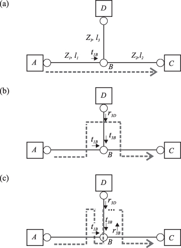
Specifically, for the situation in Figure 10.2, r1B is, for example, given by
(10.3)
![]()
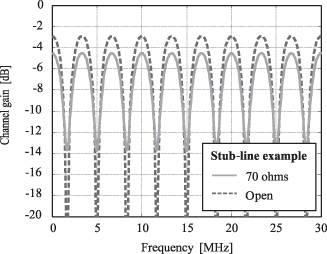
where (Z2 ![]() Z3) represents the impedance of Z2 and Z3 when connected in parallel. The other coefficients can be derived by inspection in a similar manner. Transmissions and reflections lead to a situation where a PLC signal travels in the form of a direct wave from A over B to C as displayed in Figure 10.2. Another PLC signal travels from A over B to D, bounces back to B, and reaches C, as depicted in Figure 10.2. All further signals travel from A to B, and undergo multiple bounces between B and D before they finally reach C, as can be seen in Figure 10.2. The result is a classical multipath situation, where frequency selective fading is caused by in-phase and anti-phase combinations of the arriving signal components. In reference 47 it is shown how the stub-line example from Figure 10.2 can be represented by an infinite impulse response filter. Its frequency transfer function is plotted in Figure 10.3.
Z3) represents the impedance of Z2 and Z3 when connected in parallel. The other coefficients can be derived by inspection in a similar manner. Transmissions and reflections lead to a situation where a PLC signal travels in the form of a direct wave from A over B to C as displayed in Figure 10.2. Another PLC signal travels from A over B to D, bounces back to B, and reaches C, as depicted in Figure 10.2. All further signals travel from A to B, and undergo multiple bounces between B and D before they finally reach C, as can be seen in Figure 10.2. The result is a classical multipath situation, where frequency selective fading is caused by in-phase and anti-phase combinations of the arriving signal components. In reference 47 it is shown how the stub-line example from Figure 10.2 can be represented by an infinite impulse response filter. Its frequency transfer function is plotted in Figure 10.3.
Figure 10.3. Frequency transfer function of stub line example. 70 ohms, or open termination at point D.
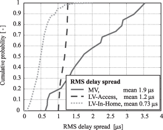
One important parameter capturing the frequency selectivity characteristics is the root mean square (rms) delay spread (DS). For example, when designing orthogonal frequency-division multiplexing (OFDM) systems [49], the guard interval might be chosen as two to three times the rms DS to deliver good system performance [50]. MV, LV-Access and LV-In-Home DS statistics extracted from references 36 and 50 are presented in Figure 10.4. The displayed rms DS statistics correspond to bands up to 30 MHz. Note that the rms DS may be obtained following various procedures. Dependent on the procedure, the results vary by up to 15% [36]. Furthermore, only a small measurement set was available for the LV-Access case. Hence, it is lacking statistical relevance. Nevertheless, Figure 10.4 gives a good indication regarding which order of rms DS to expect in the different scenarios.
Figure 10.4. Root mean square delay spread statistics.
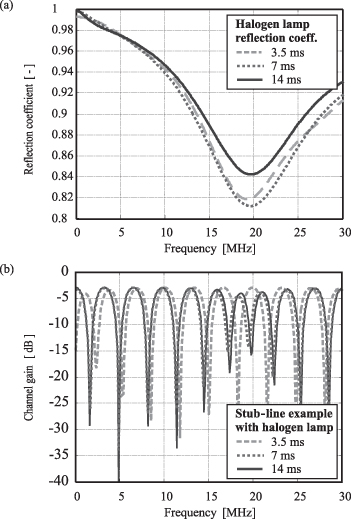
Besides multipath fading, the PLC channel exhibits time variation. It is long known that the channel changes when loads are connected or disconnected [51]. To see this, consider that the 70-Ω load in the stub-line example from Figure 10.2 is unplugged and the line remains open at point D. In this case the channel frequency transfer function changes as displayed in Figure 10.3. It is easy to imagine that similar long-term variations occur if entire line segments are connected or disconnected. In between these rather long-term switching intervals, many early PLC channel characterizations regarded the channel as stationary [52]. Only through synchronizing channel measurements with the electrical grid mains cycle, Cañete et al. were able to show that the In-Home channel changes in a cyclostationary manner [53–55]. As an example of this cyclic short-term variation, consider the measured reflection coefficient, Γ, of a halogen lamp in Figure 10.5a. It is plotted at 3.5, 7, and 14 ms after the positive zero crossing of a 50-Hz AC mains cycle. The reflection coefficient relates to the load impedance via
where Z0 is the reference impendence of the network analyzer. With the help of (10.4), the reflection coefficient measurements can be included into the stub-line example. The resulting cyclically varying channel transfer functions are displayed in Figure 10.5b. Models for long-term and cyclic short-term variation can, for example, be found in reference 56.
Figure 10.5. (a) Halogen lamp reflection coefficient. (b) Time variant frequency response for stub line example [75]. Copyright 2008 IEEE.
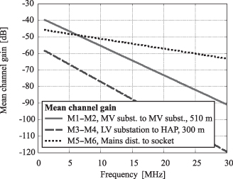
Until now the low-pass behavior of PLC channels has not been considered. It results from dielectric losses in the insulation between the conductors, and it is more pronounced in long cable segments such as outdoor underground caballing. Transfer function measurements on different cable types and for different length can be found in references 57 and 58. Using a large set of field trials, low-pass mean gain models are derived in reference 36. Over the range from 1 to 30 MHz, the mean gain in decibels is approximated by linear models. Consider again the PLC scenarios from Figure 10.1. The mean gain from the secondary transformer to the HAP, M3 to M4, is expressed as [36]
where f is frequency in megahertz, d is distance in meters, and the coefficients a1 to a4 are 0.0034 dB/(MHz m), 1.0893 dB/MHz, 0.1295 dB/m, and 17.3481 dB, respectively.
The mean gain model in dB for MV lines, as well as for LV-In-Home situations, is given by [36]
(10.6)
![]()
For the LV-In-Home situation the mean gain is given from the mains distribution board to a socket in a room, labeled M5 and M6 in Figure 10.1. The coefficients are b1 = 0.596 dB/MHz and b2 = 45.325 dB. The MV gain describes the channel between two primary transformers on the MV side, indicated by M1 and M2 in Figure 10.1. Its coefficients are b1 = 1.77 dB/MHz and b2 = 37.9 dB. In both situations the model is not distant-dependent. For the MV situation, this is due to the fact that not enough measurement results were available to construct a distant-dependent model. Hence, in this case the model is limited to situations where the distance between M1 and M2 is around 510 m. Nevertheless, correction factors are proposed in reference 36 to determine the mean gain at other distances. For the LV-In-Home situation the model is not distance-dependent because “distance” in an In-Home situation is a hard-to-define term. Power-line networks in such situation exhibit usually a large amount of branches, and a detailed floor plan to determine cable length cannot always be obtained.
Using these linear models, the mean gains for the three cases are plotted in Figure 10.6. A distance of 300 m is used in the LV-Access graph. It can be seen that the low-pass behavior is less pronounced in the In-Home case. It can further be seen that in the MV and the LV-Access situation the attenuation drastically increases with frequency. This goes well in line with the findings in reference 59 and is one of the reasons why Access networks are frequently operated in the lower frequency range (e.g., between 1 and 10 MHz), while In-Home networks might operate at frequencies above 10 MHz.
Figure 10.6. Mean channel gains.
10.5 NOISE CHARACTERISTICS
Power-line noises can be grouped based on temporal as well as spectral characteristics. Following, for example, references 58 and 60, one can distinguish among the following:
Colored Background Noise. Its PSD exhibits only long-term time variations on the scale of minutes or even hours. It is caused by the superposition of many noise sources with little power. It is often observed to decrease with increasing frequency.
Narrowband Noise. Like the colored noise, narrowband noise only exhibits long-term time variation. It is mainly caused by other radio services (Amateur Radio, television broadcasting, etc.) that get coupled into the power grid. Thus, it consists mainly of modulated sinusoidal signals with power levels clearly above the background noise.
Periodic Impulsive Noise Asynchronous to the AC Frequency. These noises often have repetition frequencies between 50 kHz and 2 MHz and are attributed to switching power supplies. They have PSDs that decrease with frequency, and they are sometimes considered as part of the colored background noise.
Periodic Impulsive Noise Synchronous to the AC Frequency. They occur with repetition frequencies that are a multiple of the AC frequency. For example, in a 50-Hz network they would occur at 50 or 100 Hz. They are attributed to net-synchronous power converters used in dimmers or, more generally, to all kinds of diode-containing rectifier circuitry. The impulses are usually very narrow in the time domain and can have a considerable amplitude, with the consequence that they can have an adverse effect over a wide frequency range.
Aperiodic Impulsive Noise. This noise occurs at random intervals and may consist of several consecutive spikes in the time domain also called bursts. Aperiodic impulsive noise is attributed to all kinds of switching effects (e.g., within electrical motors or in condenser discharge lamps). Its amplitude can be significant (e.g., 50 dB above the colored noise floor), and its randomness in time makes it specifically difficult to deal with from a communication system point of view. In environments only lightly affected by this noise, one might observe 1 impulse in 10 seconds, while in heavily affected environments there might be around 100 impulses per second.
In reference 58, all these noises are modeled directly at the receiver. Time-invariant additive white Gaussian noise (AWGN) plus an exponentially decaying spectral filtering process is used for the conglomerate of colored background noise and the periodic impulsive noise asynchronous to the mains. Further, narrowband noise is modeled by a superposition of sinusoidal signals with different amplitudes and random phases. Periodic impulsive noise synchronous to the AC mains is modeled by filtering AWGN and adding it at synchronous periodic intervals. Finally, the aperiodic noise is also generated from filtering AWGN, but by adding it at random intervals that are determined by an underlying Markov process. A special procedure based on two interconnected Markov processes is used to implement noise bursts.
Instead of modeling the noise directly at the receiver, Cañete et al. proposed to model the noise at its origin and to filter it by the channel transfer function [53, 61]. Advantages are that temporal correlation effects between channel changes and noise variations, as well as correlated noise events as seen by different receivers, could be modeled. Disadvantages are that in many cases the channel transfer functions to the different receivers might not be known, or complex channel modeling might be required to obtain them.
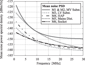
A statistical approach to average colored background noise modeling is presented in reference 36 based on a large amount of noise measurements in MV as well as LV-Access and LV-In-Home situations. Although a lot of the details get lost by averaging, the results can still deliver some interesting rule of thumb when one wants to determine a likely average noise level. One general finding is that the mean noise power falls off exponentially with frequency. Derived from reference 36, the mean noise PSD in dBm/Hz is given by
(10.7)
![]()
where the last term normalizes out the 30-kHz bandwidth used in the noise measurement process. The coefficients c1 to c3 are given in Table 10.1. The resulting noise models correspond to the measurement points M1 to M6 in Figure 10.1 and are plotted in Figure 10.7.
TABLE 10.1. Mean Noise Model Coefficients [36]
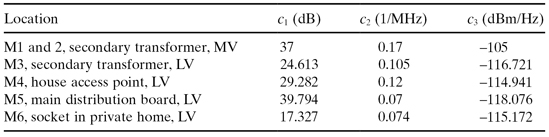
Figure 10.7. Mean noise power spectral densities.
10.6 MEAN SIGNAL-TO-NOISE RATIO
Assume that a power-line signal with ![]() S = −55 dBm/Hz may be injected. Using the gain and noise models from (10.5) to (10.7) the mean SNR can be approximated as
S = −55 dBm/Hz may be injected. Using the gain and noise models from (10.5) to (10.7) the mean SNR can be approximated as
(10.8)
![]()
The mean SNRs for the various connections between the measurement points M1 to M6 are plotted in Figure 10.8. One should note that although the channel gain between two measurement points is symmetric, the noise at the measurement points differs. Hence, five different graphs are produced.
Figure 10.8. Mean SNRs for the various connections between the measurement points M1 to M6.
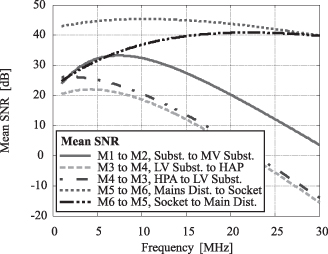
It can be seen that especially the lower part of the spectrum, up to 10 MHz, is very well suited for Access and Backhaul applications. Furthermore, for In-Home applications the entire spectrum from 1 to 30 MHz promises high mean SNRs on the order of 40 dB, which also goes well in line with the findings in reference 62. The results show that there is a high potential for PLC if the estimated mean SNRs can be exploited in PLC modems. However, the presented results have to be handled with care. One should bear in mind that the mean SNR models from reference 36 exhibit a significant standard deviation. With respect to the individual link SNRs, the standard deviation ranges from 13.5 to 23.4 dB. Furthermore, effects due to frequency selectivity, narrowband interference, impulsive noise, and time variation were not considered. Whether the estimated mean SNRs translate into high PLC data rates depends on the PLC modem’s signal processing algorithms and its component quality.
10.7 PLC TECHNOLOGY OVERVIEW
We will now look at the PHY and MAC of the consortia-backed specifications HomePlug AV and UPA (Access/DHS), as well as at the upcoming international standard ITU-T G.hn. An overview of the main parameters is provided in Table 10.2. The HD-PLC specification and the upcoming IEEE P1901 standard are not considered, to confine the overview to a concise and manageable level. Nevertheless, the interested reader may refer to reference 63 for a comparison that includes HD-PLC. Besides, one should note that IEEE P1901 basically includes the PHY of HD-PLC and HomePlug AV. Note further that ITU-T G.hn is applicable not only to power lines but also to phone lines and coaxial cables. However, only the power-line-specific parameters are presented here. Finally, note that all reviewed PLC systems have a robust communication mode. However, for the sake of simplicity, the following subsections will only deal with the modulation and coding of the data payload in normal operation. Similarly, for the sake of simplicity, details on interleaving and scrambling are omitted. The interested reader may refer to the actual documents [16, 22–24, 31] instead.
TABLE 10.2. PLC Systems—Parameter Overview
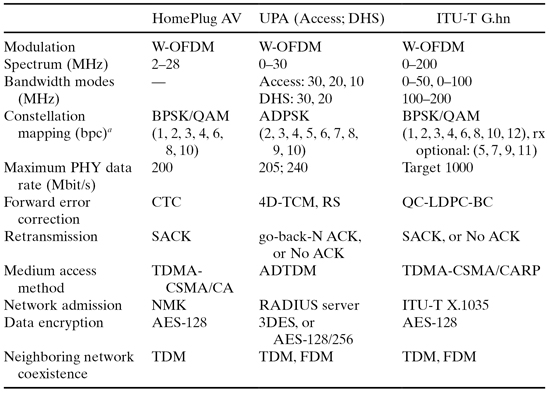
a bpc, bits per carrier.
10.7.1 Windowed OFDM Modulation
All PLC systems in Table 10.2 use windowed orthogonal frequency division multiplexing (W-OFDM) [49], a multicarrier technology that is, for example, also used in Wi-Fi, WiMAX, and xDSL. The data bits to be transmitted are first mapped onto a constellation point in the complex plain. A set of constellation points is grouped to form a so-called OFDM symbol. The so assembled frequency domain symbol is passed through an inverse fast Fourier transform (IFFT) to obtain a time domain OFDM symbol. A cyclic prefix (CP) is added, by copying some of the time domain samples from the end of the symbol to its beginning. Afterwards, windowing and possibly up-conversion are performed before the samples are sent to the digital-to-analog converter (DAC). From there, the analog signal is fed to a power amplifier before it is coupled onto the power line by capacitive or inductive coupling devices.
At the receiver the signal is decoupled from the power line and is sent to an automatic gain control (AGC) stage. This AGC ensures that the received signal strength, which after propagating through the PLC channel exhibits a considerable dynamic range, falls well into the limited input conversion range of the analog-to-digital converter (ADC). Afterwards, a carefully selected subset of the obtained digital time domain samples is passed through a fast Fourier transform (FFT). The subset selection, better known as synchronization, removes the CP that had been inserted by the transmitter. After the FFT, the signal consists of a set of raw soft symbol points in the frequency domain. Dependent on the used constellation mapping, which can be coherent or differential, the raw soft symbols might have to be phase-rotated and scaled before they can be related to the originally transmitted constellation points and in the sequel to the transmitted bits.
Clearly, the exact procedure within the PLC transmitter and the PLC receiver is vendor discretionary, and performance can differ significantly even if two vendors implement the same communication specification. The fact that all PLC systems in Table 10.2 deploy OFDM is explained by the manifold advantages of OFDM when used over power-line channels:
- OFDM allows tight carrier spacing and therefore enjoys high spectral efficiency.
- As pointed out earlier, the PLC channel is frequency-selective with sometimes long multipath echoes. Nevertheless, dependent on the CP length and the quality of the synchronization process, OFDM makes it possible to avoid intersymbol interference (ISI).
- Simple frequency domain equalization may be deployed on a per carrier basis. Furthermore, the underlying IFFT and FFT signal processing operations are well understood, with the consequence that highly efficient algorithms exist to implement the required operations on a semiconductor chip.
- The fact that OFDM symbols consist of a set of orthogonal carriers in the frequency domain makes it easy not to load some carriers with signal energy. This way, adaptive notching and power mask requirements, imposed by EMC regulations, can be flexibly implemented. Furthermore, through the option to avoid some “bad” carriers, OFDM exhibits an inherent resilience to jammers such as narrowband radio stations.
10.7.2 Constellation Mapping
As already mentioned, to form an OFDM symbol in the frequency domain, a complex constellation point is assigned to every carrier. All PLC technologies in Table 10.2 have the option to select among various constellations with different size and therefore with a different number of bits per carrier (bpc). This task is performed by vendor-specific bit-loading algorithms. However, a standard approach would be to select a constellation that together with the deployed forward error correction (FEC) scheme leads to a certain expected block error rate (BLER) after decoding.
Coherent and differential constellation mapping mechanisms exist. Coherent methods require that the receiver compensate for amplitude and phase variations introduced by the channel. Channel estimation and channel tracking mechanisms are required. On the other hand, differential mechanisms encode the information in the difference between two symbols. Hence, to decode the symbol information the receiver uses the previous symbol as reference. Direct channel estimation and tracking is not required, which makes differential constellation mapping robust against abrupt channel changes. Nevertheless, the spectral efficiency of the differential schemes is usually reduced [64].
Also hybrids between coherent and differential mapping exist. An example is the amplitude differential phase shift keying (ADPSK) scheme used by the UPA specification. Here information is differential encoded in phase, allowing quick recovery after abrupt channel changes. In good situations—that is, a stable channel and low noise—information is additionally coherently encoded in various amplitude levels. The constellation points of 5 bpc ADPSK are plotted in Figure 10.9a as an example.
Figure 10.9. Odd constellation examples. (a) UPA 32-ADPSK. (b) ITU-T G.hn 32-QAM.
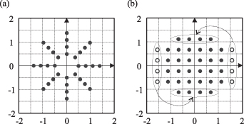
The other technologies in Table 10.2, HomePlug AV and ITU-T G.hn, use purely coherent mappings. In binary phase shift keying (BPSK) 1 bpc is mapped to two antipodal points. Furthermore, quadrature amplitude modulation (QAM) can be used where information is encoded through amplitude variations in the complex plain. HomePlug AV supports the bpc (1, 2, 3, 4, 6, 8, 10). ITU-T G.hn additionally supports 12 bpc and makes the support of odd constellation QAM schemes with bpc (5, 7, 9, 11) mandatory for the transmitter but optional for the receiver. An example of the 5 bpc ITU-T G.hn 32-QAM constellation points can be found in Figure 10.9b. As indicated, odd constellations can be constructed by first setting a fat rectangle of points and then transforming the outer columns into rows.
10.7.3 Forward Error Correction
Forward error correction—that is, adding redundant bits to the transmitted data that help the receiver to detect the original information bits even in a harsh communication channel—is a standard procedure in modern digital communications. Two main classes of FEC codes, convolutional codes and block codes, exist. Convolution codes work on continuous streams of data, while block codes work on data blocks [65, 66]. It has also been common practice to concatenate an inner convolutional code with an outer block code, used for example in DVB-T or ADSL.
As seen in Table 10.2, convolutional four-dimensional trellis-coded modulation (4D-TCM) and a Reed–Solomon (RS) block code are concatenated in the UPA specification. The other two technologies use only a single code. HomePlug AV uses a convolutional Turbo code (CTC), which consists of two interleaved convolutional coders. Similar CTCs are, for example, also used in the third-generation wireless standards UMTS and CDMA2000. The ITU-T G.hn/G9960 standard uses a quasi-cyclic low-density parity-check block code (QC-LDPC-BC), which is also used, for example, in WiMAX (IEEE 802.16e), 10GBase-T Ethernet (IEEE 802.3an), and DVB-S2. Both CTC and QC-LDPC-BC have a higher spectral efficiency than the 4D-TCM RS solution. Comparing CTC and QC-LDPC-BC, it turns out that at BLER > 10−3 they have similar coding gain, albeit QC-LDPC-BCs allow higher throughputs. At BLER < 10−3, QC-LDPC-BCs outperform CTCs in coding gain and throughput when implementing similarly complex decoding structures [67].
10.7.4 Retransmission Schemes
Any FEC scheme can only correct a limited amount of errors. When, for example, a strong impulsive noise is experienced at the PLC receiver, it could be that the deployed FEC cannot decode the incoming signal correctly. In such an event, the PHY layer would inform the higher layers about the incorrectly received data. Dependent on the transfer control protocol, the receiver might then request the transmitter to resend the data. Different retransmission schemes exist. A general overview can, for example, be found in reference 68.
UPA has two transfer control protocol modes. In ACK mode a sliding window go-back-N acknowledgement procedure is implemented. The receiver keeps track of the received data packets and sends the packet identifier of the last correctly received packet back to the transmitter. The transmitter keeps track of transmitted packets and triggers a retransmission based on the ACK information if deemed necessary. In the second mode, called No ACK, the receiver only keeps track of the correctly received sequence of data packets; however, it cannot request a retransmission.
HomePlug AV uses a selective repeat acknowledgment (SACK) transfer control protocol. The receiver acknowledges the correct reception of PHY blocks. Only those blocks that are not positively acknowledged will be retransmitted. While SACK avoids duplicate transmissions of correct packets, the implementation complexity is higher, due to increased buffering requirements at the receiver.
ITU-T G.hn supports, like UPA, two modes of operation: ACK mode and No ACK mode. However, in ACK mode it uses a selective repeat ARQ scheme, similar to the one used in HomePlug AV. Only the packets that are not positively acknowledged are retransmitted. The receiver can still accept and acknowledge packets that it receives after the reception of an erroneous packet. The No ACK operation can be used in situations with very stable and high SNRs, as well as for services where occasional packet errors may be tolerated.
10.7.5 Medium Access Control
Until now only a simple PLC network topology with a single transmitter and a single receiver was considered. However, many PLC modems might be connected to the same power-line network. In this case, medium access control (MAC) protocols have to arbitrate access to the shared power-line medium. When QoS has to be guaranteed, centrally coordinated MAC protocols have advantages over probabilistic ones like carrier sense multiple access (CSMA). Therefore, although all PLC technologies in Table 10.2 use some kind of CSMA, QoS demanding data is scheduled in all of them using a centrally coordinated master/slave topology.
In HomePlug AV, the master is called Central Coordinator (CCo). The CCo assigns timeslots to the other AV nodes and broadcast these assignments within a so-called beacon region. The entire beacon is repeated every two AC mains cycles, leading to a repetition period of 33.33 ms or 40 ms in a 60- and a 50-Hz mains grid, respectively. The beacon consists of the beacon region, a CSMA region, and a contention-free region. Usually, applications that have strict QoS requirements are scheduled in the contention-free region. Delay-tolerant applications contend for access in the CSMA region. The overall MAC protocol is also referred to as time division multiple access, carrier sense multiple access with collision avoidance (TDMA-CSMA/CA).
The MAC protocol of the UPA specification uses a control signal called a token. The token is passed from a master to its slaves. With the token, a slave receives the right to put data onto the shared power-line medium. After the slave has no more data to send, or once its allocated maximum time is up, it returns the token to the master. The UPA Access part specifies three entities: The head end (HE), the time division repeater (TDR), and the customer premises equipment (CPE). Equivalently, UPA DHS specifies the access point, the repeater, and the end point. Considering an Access network, the HE is the master to all nodes in its direct reach, be it CPEs or TDRs. The TDRs function as masters to nodes that are hidden to the HE. The UPA DHS MAC works along the same lines. The MAC protocol is also said to implement advanced dynamic time division multiplexing (ADTDM).
ITU-T G.hn uses a mix of the MAC features of HomePlug AV and UPA. The important network entities are called domain master, relay node, and regular node. The domain master assigns transmission opportunities (TXOPs) to all nodes to facilitate QoS support. The information is conveyed in a so-called medium access plan (MAP). TXOPs exist in two flavors, contention free (CFTXOP) and shared (STXOP). During CFTXOP, only a preassigned transmitter is allowed to send data to ensure QoS. The STXOPs are themselves subdivided into contention-free timeslots (CFTS) and contention-based timesslots (CBTS). During CFTS the nodes perform an implicit token passing, which means that, following an order, only one node is allowed to transmit at a time. In the CBTS, all nodes contend for medium access using a carrier sense multiple access with collision avoidance and resolution protocol (CSMA/CARP) [68]. Furthermore, ITU-T G.hn knows three modes of domain operation called peer-to-peer mode (PM), centralized mode (CM), and unified mode (UM). In PM, data packets may directly be exchanged between any node A and any node B as long as both are within reach of each other. Relaying is not allowed. In CM, all data packets are first transmitted to the so-called domain access point (DAP), which often coincides with the domain master. From the DAP the data packets are retransmitted to the destination node. In CM the DAP is the only allowed relay node. Finally, in UM, connections are of a peer-to-peer type. However, multiple relay nodes may exist to connect two far-away nodes that cannot directly see each other. Which of the three modes is used is decided and signaled by the domain master.
10.7.6 Security
Although PLC signals are mainly confined to the physical line, it is possible that they are received by a third party. Thus, all PLC technologies in Table 10.2 specify mechanisms to restrict the access to a network. Furthermore, data encryption techniques are used.
More specifically, the UPA specifications use a remote authentication dial in user service (RADIUS) [69], to allow the master to manage access of slaves to a network. Once a node is admitted, data are encrypted using the triple data encryption standard (3DES) [68]. Alternatively, UPA DHS may use the 128-bit or the 256-bit advanced encryption standard (AES) [70]. AES is commonly regarded as a successor of 3DES [68].
To connect to a HomePlug AV network, a node must have knowledge of the so-called network membership key (NMK)—for example, through the insertion of the right password. A node with correct NMK is passed the network encryption key (NEK). This NEK is then used to encrypt data transmissions with the 128-bit AES.
ITU-T G.hn uses an advanced authentication and secure admission procedure based on ITU-T X.1035 [14]. Moreover, ITU-T G.hn uses unique encryption keys for each pair of communicating nodes or per multicast group. The encryption mechanism is based on AES-128.
10.7.7 Coexistence and Neighboring Network Support
With an increasing penetration of PLC networks, the risk that these networks interfere with each other also increases. In the worst case, interference can be so significant that neither of the interfering networks may operate satisfactory. Hence, if not tackled, this so-called neighboring network interference could cause very negative consumer experience and limit consumer acceptance of PLC technology as a whole. Therefore, UPA and HomePlug have developed mechanisms to make networks of the same specification coexist. These will be outlined in the following:
The UPA coexistence specification [22] demands that UPA networks detect their mutual presence by transmitting and sensing a preamble signal. If neighboring UPA networks are detected, all nodes follow a fixed set of rules to avoided interference. The avoidance process is based on dynamic frequency division multiplexing (FDM) as well as dynamic time division multiplexing (TDM). For this purpose the spectrum is subdivided into three bands called FB1 to FB3. FB1 refers to frequencies below 12 MHz, and FB2 refers to frequencies above 13 MHz. Finally, FB3 refers to the entire spectrum from 1 to 30 MHz. Besides, the time interval between transmitted preamble signals is subdivided into 12 timeslots. The result is a time-frequency grid over which transmissions of neighboring UPA networks are scheduled. Consider, for example, the situation where an UPA In-Home network operates over the entire frequency spectrum, that is, FB3. At some point the presence of an UPA Access network is detected in FB1. In this case the In-Home network switches its data transmission to band FB2. However, it continues to listen to the preamble signals over FB1 and FB2. Should it detect that the Access network has become inactive, it may dynamically expand its operation using the full spectrum, that is, FB3, again. Consider another example where one UPA In-Home network is using FB3 while a second UPA In-Home network is powered up that would like to use FB3 as well. Listening to the preamble both networks detect each other and start to use preassigned timeslots. More precisely, the first In-Home network starts to use timeslot 1 and 7. The second network uses timeslots 3 and 9. The remaining 8 timeslots may be used by either of the two based on a controlled contention process. In case of congestion, these slots are shared evenly and collision-free. Besides, the UPA coexistence specification supports spatial reuse. To understand the idea behind spatial reuse, imagine a network with five nodes, labeled A, B, C, D, and E. Imagine further that all nodes are within reach of node C. However, nodes A and B are not within reach of node D and E, and vice versa. In such situations, C may operate as a relay, for example, to establish a connection between A and E or between B and D. More importantly, nodes A and B may communicate with each other using the same timeslot and the same frequency band as E and F. Having several peer-to-peer connections operating in parallel, while exploiting merely spatial separation, can boost overall network throughput significantly.
Looking at HomePlug AV, several neighboring AV and HomePlug 1.0 networks can detect each other. Similar to the UPA networks, they transmit and sense preamble signals. Once a neighboring network situation is detected, the different CCos negotiate who may use which timeslots in the beacon’s contention-free region. Only one network is allowed to transmit in every timeslot, this way implementing a TDM system. Furthermore, all the nodes may contend for medium access in the beacon’s CSMA region.
It was early recognized that merely coexistence between same-technology networks was not sufficient to gain widespread consumer acceptance. Hence, in 2005 the Consumer Electronics Powerline Communication Alliance (CEPCA) [71] was brought to live. It was founded by Panasonic, Mitsubishi, and Sony with the objective to develop specifications that enable the coexistence between different In-Home technologies as well as between different In-Home and Access technologies. A tight cooperation with UPA was quickly established, which resulted in the submission of a coexistence standard proposal to the IEEE P1901 standardization process. The proposal was several times modified and amended until a proposal including HomePlug and ITU-T G.hn coexistence mechanisms was finally confirmed at the end of 2008. Around the same time, ITU-T G.cx was formed to tackle coexistence of ITU-G.hn with existing home networking technologies. Although not finally consented, it is likely that IEEE P1901 as well as ITU-T G.hn devices will incorporate an intersystem protocol (ISP) containing technical elements from the UPA and the HomePlug coexistence protocols described earlier [72]; that is, neighboring networks detect each others’ presence with the help of preamble signals. Afterwards, TDM and FDM mechanism are applied to avoid destructive intersystem interference when operating on the same medium [73, 74].
10.8 CONCLUSIONS
An overview of past, present, and upcoming broadband power-line technologies was provided. It can be concluded that current-generation PLC technologies complement other wire line and wireless technologies. The main advantages of PLC are that no new wires are required and that the coverage is in many cases higher than that of wireless solutions.
A large amount of PLC deployment scenarios exists, which makes it difficult to come up with a “one fits all” channel and noise characterization. Thus, only average channel and noise models have been presented throughout this text. However, many references have been provided, pointing the interested reader to parametric, as well as physical, models. Based on the presented mean SNR models, it can be concluded that In-Home scenarios exhibit usually higher SNRs than Access scenarios. Furthermore, Access scenarios suffer severe SNR degradation with increasing operating frequency.
To make PLC a widespread success, it is essential to come to a single broadly adopted standard. The upcoming ITU-T G.hn standard, with its single PHY and single MAC, can fill this gap, and it becomes even more attractive because it is applicable not only to PLC, but also to coaxial cables and phone lines. Thus, for the first time a standard has the potential to unify the entire wire line industry. This is good news for consumers, as well as for consumer equipment manufacturers, because they are no longer forced to choose among non-coexisting proprietary technologies.
REFERENCES
1. K. Dostert, Telecommunications over the power distribution grid—Possibilities and limitations, in International Symposium on Power Line Comms and Its Applications (ISPLC), pp. 1–9. Essen, Germany, April 1997.
2. P. A. Brown. Power line communications—past present and future, in International Symposium on Power Line Communicatons and Its Applications (ISPLC), September 1999, pp. 1–8.
3. J. Abad, A. Badenes, J. Blasco, J. Carreras, V. Dominguez, C. Gomez, S. Iranzo, J. C. Riveiro, D. Ruiz, L. M. Torres, and J. Comabella, Extending the power line LAN up to the neighborhood transformer, IEEE Commun. Mag., Vol. 41, No. 4, pp. 64–70, April 2003.
4. G. Held, Understanding Broadband over Power Line, CRC Press, Boca Raton, FL, 2006.
5. A. Sendí Escalona, R. Saorín Adán, J. Hartmann, and J. A. Garrigosa, White paper AMR. IST Integrated Project Deliverable D41v1.1, The OPERA Consortium, December 2004. EC/IST FP6 Project No 507667.
6. M. Koch, H. Hirsch, and M. Ianoz, Powerline communication for the coordination of distributed energy generation, in 7th International Symposium on Electromagnetic Compatibility and Electromagnetic Ecology, Saint-Petersburg, Russia, June 2007, pp. 40–43.
7. Q. Liu, B. Zhao, Y. Wang, and J. Hu, Experience of AMR systems based on BPL in China, in IEEE International Symposium on Power Line Communications and Its Applications (ISPLC), Dresden, Germany, April 2009, pp. 280–284.
8. A. Dutta-Roy, Networks for home, IEEE Spectrum, Vol. 36, pp. 26–33, December 1999.
9. K. Dostert, Powerline Communications, Prentice-Hall, Upper Saddle River, NJ 2001.
10. Intellon, Home page: http://www.intellon.com/, September 2009.
11. DS2, Design of Systems on Silicon, Home page: http://www.ds2.es/, September 2009.
12. HomePlug Powerline Alliance, Home page: http://www.homeplug.org/home, September 2009.
13. Universal Powerline Association (UPA), Home page: http://www.upaplc.org/, September 2009.
14. Telecommunication Standardization Sector, Study Group 17, Password-authenticated key exchange (PAK) protocol. ITU-T Recommendation X.1035, International Telecommunication Union (ITU), February 2007.
15. M. K. Lee, R. E. Newman, H. A. Latchman, S. Katar, and L. Yonge, HomePlug 1.0 powerline communication LANs-protocol—Description and performance results, Int. J. Commun. Syst., Vol. 16, pp. 447–473, 2003.
16. HomePlug Powerline Alliance, HomePlug AV baseline specification, May 2007. Version 1.1.
17. HomePlug Powerline Alliance, HomePlug AV white paper. Technical Report HPAVWP-050818, HomePlug Powerline Alliance, 2005.
18. K. H. Afkhamie, S. Katar, L. Yonge, and R. Newman, An overview of the upcoming HomePlug AV standard, in International Symposium on Power Line Communications and Its Applications (ISPLC), Vancouver, Canada, April 2005, pp. 400–404.
19. S. Gavette, HomePlug AV technology overview. White paper, Microsoft, April 2006.
20. Telecommunications Industry Association (TIA), Committee: TR-30.1. Medium-speed (up to 14 Mbps) power line communications (PLC) modems using windowed OFDM, May 2008. TIA-1113.
21. Open PLC European Research Alliance (OPERA), Home page: http://www.istopera.org/, September 2009.
22. OPERA Consortium, Opera technology specification—Part 1. European Union Project Deliverable, SSWG v1.0, January 2006. IST Integrated Project No 507667.
23. OPERA Consortium, Opera technology specification—Part 2. European Union Project Deliverable, SSWG v1.0, January 2006. IST Integrated Project No 507667.
24. Universal Powerline Association (UPA), UPA—Digital Home Specifications (UPA DHS), v 1.0., February 2006.
25. S. Arroyo, Digital home specification white-paper, Technical Report 1.0, Universal Powerline Association (UPA), May 2006.
26. Panasonic Communications Co., Ltd., Home page: http://panasonic.net/corporate/segments/pcc/, September 2009.
27. High Definition Power Line Communication Alliance (HD-PLC), Home page: http://www.hd-plc.org, September 2009.
28. Gigle home page: http://www.gigle.biz/, September 2009.
29. J. Simón, J. P. Faure, and R. Martínez, White paper: Comparison of access technologies. IST Integrated Project Deliverable D7v2.1, The OPERA Consortium, March 2009. IST Integrated Project No 026920.
30. National Institute of Standards and Technology (NIST), U.S. Department of Commerce. NIST framework and roadmap for smart grid interoperability standards. NIST Draft Publication, Release 1.0, September 2009.
31. International Telecommunications Union (ITU). ITU-T Recommendation G.9960, Unified High-Speed Wire-Line Based Home Networking Transceivers—Foundation, August 2009.
32. HomeGrid Forum, Home page: http://www.homegridforum.org/home, September 2009.
33. Institute of Electrical and Electronic Engineers (IEEE), Standards Association, Working group P1901. Home page: http://grouper.ieee.org/groups/1901/, September 2009.
34. J. Byrne, Fruitless battle of proprietary home-networking tech nears end. Blog, posted by the Linley Group Silicon Valley, http://blog.linleygroup.com/2009/06/fruitless-battle-of-proprietary-home.html, June 2009.
35. J. C. Dvorak, HDMI: Who needs this aggravation? PC Magazine, Davis Media Inc., http://www.pcmag.com/article2/0,2817,2349468,00.asp, July 2009.
36. P. Meier, M. Bittner, H. Widmer, J.-L. Bermudez, A. Vukicevic, M. Rubinstein, F. Rachidi, M. Babic, and J. Simon Miravalles, Pathloss as a function of frequency, distance and network topology for various LV and MV European powerline networks. Project Deliverable, EC/IST FP6 Project No 507667 D5v0.9, The OPERA Consortium, April 2005.
37. A. Rubinstein, F. Rachidi, M. Rubinstein, A. Vukicevic, K. Sheshyekani, W. Bäschelin, and C. Rodríguez-Morcillo, EMC guidelines. IST Integrated Project Deliverable D9v1.1, The OPERA Consortium, October 2008. IST Integrated Project No 026920.
38. A. Vukicevic, Electromagnetic Compatibility of Power Line Communication Systems. Dissertation, École Polytechnique Fédérale de Lausanne, Lausanne, Switzerland, June 2008, No 4094.
39. S. Galli, T. Banwell, and D. Waring, Power line based LAN on board the NASA space shuttle, In IEEE 59th Vehicular Technology Conference, Vol. 2, May 2004, pp. 970–974.
40. S. Tsuzuki, M. Yoshida, and Y. Yamada, Characteristics of power-line channels in cargo ships, in International Symposium on Power Line Communications and Its Applications (ISPLC), Pisa, Italy, March 2007, pp. 324–329.
41. V. Degardin, M. Lienard, P. Degauque, E. Simon, and P. Laly, Impulsive noise characterization of in-vehicle power line, IEEE Trans. Electromagn. Compat., Vol. 50, No. 4, pp. 861–868, November 2008.
42. W. Baeschlin, S. Arroyo, L. Feltin, M. Koch, B. Wirth, J.-P. Faure, and M. Heina, First report on the status of PLC standardisation activities in CISPR, European Union Project Deliverable D30, OPERA Consortium, February 2008, IST Integrated Project No. 026920.
43. W. Baeschlin, L. Feltin, J.-P. Faure, M. Rindchen, and H. Hirsch. Second report on the status of PLC standardisation activities in CISPR, European Union Project Deliverable D31, OPERA Consortium, January 2009, IST Integrated Project No. 026920.
44. Comité International Spécial des Perturbations Radioélectriques, Information technology equipment; radio disturbance characteristics; limits and methods of measurement, International Standard Norme CISPR 22, Edition 6.0, ICS CISPR, September 2008.
45. FCC, Title 47 of the code of federal regulations (CFR), Technical Report 47 CFR §15, Federal Communications Commission, July 2008.
46. M. Zimmermann and K. Dostert, A multi-path signal propagation model for the power line channel in the high frequency range, in International Symposium on Power-line Communications and Its Applications (ISPLC), Lancaster, UK, April 1999, pp. 45–51.
47. L. T. Berger and G. Moreno-Rodríguez, Power line communication channel modelling through concatenated IIR-filter elements, Acad. Publisher J. Commun., Vol. 4, No. 1, pp. 41–51, February 2009.
48. D. M. Pozar, Microwave Engineering, 3rd edition, John Wiley & Sons, Hoboken, NJ, 2005.
49. R. van Nee and R. Prasad, OFDM for Wireless Multimedia Communications. Universal personal communication. Artech House Publishers, Norwood, MA, 2000.
50. S. Galli, A simplified model for the indoor power line channel, in IEEE International Symposium on Power Line Communications and Its Applications (ISPLC), Dresden, Germany, March 2009, pp. 13–19.
51. F. J. Cañete Corripio, L. Díez del Río, and J. T. Entrambasaguas Muñoz, A time variant model for indoor power-line channels, in International Symposium on Power Line Communications (ISPLC), Malmö, Sweden, March 2001, pp. 85–90.
52. A. J. Han Vinck and G. Lindell, Summary of contributions at ISPLC 1997–2001, in International Symposium on Power Line Communications (ISPLC), Malmö, Sweden, March 2001, pp. 383–413.
53. F. J. Cañete, L. Díez, J. A. Cortés, and J. T. Entrambasaguas, Broadband modelling of indoor power-line channels, IEEE Trans. Consumer Electron., Vol. 48, No. 1, pp. 175–183, February 2002.
54. J. A. Cortés, F. J. Cañete, L. Díez, and J. T. Entrambasaguas, Characterization of the cyclic short-time variation of indoor power-line channels response, in International Symposium on Power Line Communications and Its Applications (ISPLC), Vancouver, Canada, April 2005, pp. 326–330.
55. F. J. Cañete Corripio, J. A. Cortés Arrabal, L. Díez del Río, and J. T. Entrambasaguas Muñoz, Analysis of the cyclic short-term variation of indoor power line channels, IEEE J. Sel. Areas Commun., Vol. 24, No. 7, pp. 1327–1338, July 2006.
56. S. Sancha, F. J. Cañete, L. Díez, and J. T. Entrambasaguas, A channel simulator for indoor power-line communications, in IEEE International Symposium on Power Line Communications and Its Applications (ISPLC), Pisa, Italy, March 2007, pp. 104–109.
57. M. Zimmermann and K. Dostert, A multipath model for the powerline channel. IEEE Trans. Commun., Vol. 50, No. 4, pp. 553–559, April 2002.
58. M. Babic, M. Hagenau, K. Dostert, and J. Bausch, Theoretical postulation of PLC channel model, IST Integrated Project Deliverable D4v2.0, The OPERA Consortium, March 2005.
59. H. Liu, J. Song, B. Zhao, and X. Li, Channel study for medium-voltage power networks, in IEEE International Symposium on Power Line Communications (ISPLC), Orlando, FL, March 2006, pp. 245–250.
60. M. Zimmermann and K. Dostert, An analysis of the broadband noise scenario in power-line networks, in International Symposium on Power Line Commun. and Its Applications (ISPLC), Limerick, Ireland, April 2000, pp. 131–138.
61. F. J. Cañete, J. A. Cortés, L. Díez, and J. T. Entrambasaguas, Modeling and evaluation of the indoor power line transmission medium, IEEE Commun. Mag., Vol. 41, No. 4, pp. 41–47, April 2003.
62. A. Schwager, L. Stadelmeier, and M. Zumkeller, Potential of broadband power line home networking, in Second IEEE Consumer Communications and Networking Conference, January 2005, pp. 359–363.
63. P. Siohan, A. Zeddam, G. Avril, P. Pagani, S. Person, M. Le Bot, E. Chevreau, O. Isson, F. Onado, X. Mongaboure, F. Pecile, A. Tonello, S. D’Alessador, S. Drakul, M. Vuksic, J. Baudais, A. Maiga, and J. Herald, State of the art, application scenario and specific requirements for PLC. European Union Project Deliverable D3.1 v1.0, OMEGA, 2008. IST Integrated Project No ICT-213311.
64. J. G. Proakis, Digital Communications, 4th edition, McGraw-Hill International Series in Electrical Engineering: Communications and Signal Processing, McGraw-Hill, 2001.
65. T. M. Cover and J. A. Thomas, Elements of Information Theory, John Wiley & Sons, New York, 1991.
66. T. K. Monn, Error Correction Coding, Mathematical Methods and Algorithms, John Wiley & Sons, Hoboken, NJ, 2005.
67. S. Galli, PLC standardization progress and some PHY considerations. Keynote Speech at IEEE International Symposium on Power Line Communications (ISPLC), Dresden, Germany, March 2009. Digital Object Identifier 10.1109/ISPLC.2009.4913389.
68. A. S. Tannenbaum, Computer Networks, 4nd edition, Prentice-Hall International, Englewood Cliffs, NJ, 2003.
69. J. Hassell, RADIUS—Securing Public Access to Private Resources, O’Reilly & Associates, Sebastopol, CA, 2002.
70. National Institute of Standards and Technology (NIST), U.S. Department of Commerce. Specification for the advanced encryption standard (AES). Federal Information Processing Standards Publication 197, November 2001.
71. Consumer Electronics Powerline Communication Alliance (CEPCA), Home page: http://www.cepca.org/, September 2009.
72. B. O’Mahony, C. Gómez, J. Egan, V. Oksman, M. Finocchiaro, and S. Galli, G.hn compatibility with existing home networking technologies. HomeGrid Forum White Paper, April 2009, Revision 1.0.
73. S. Galli, A. Kurobe, and M. Ohura, The inter-PHY protocol (IPP): A simple coexistence protocol for shared media, in IEEE International Symposium on Power Line Communications and Its Applications (ISPLC), Dresden, Germany, March 2009, pp. 194–200.
74. Institute of Electrical and Electronics Engineers (IEEE) Standards Association, Working group P1901. IEEE P1901 Draft standard for broadband over power line networks: Medium access control and physical layer specifications, July 2009.
75 G. Moreno-Rodríguez and L. T. Berger. An IIR-filter approach to time variant PLC-channel modelling, in IEEE International Symposium on Power Line Communications and Its Applications (ISPLC), Jeju, South Korea, April 2008, pp. 87–92.