11
POWER-LINE COMMUNICATIONS AND SMART GRID
With the ever-increasing demand for high-speed data communication and its quality of service (QoS), broadband connectivity to and within the home has been available to consumers through various technologies. Among those technologies, power-line communications (PLC) is becoming an excellent candidate for providing broadband connectivity as it exploits an already existing infrastructure. This infrastructure is much more pervasive than any other wired alternatives, and it allows virtually every line-powered device to take advantage of value added services that are being developed. Therefore, PLC may be considered as the technological enabler of a variety of future applications that probably would not be available otherwise [1].
PLC is not new. At a very early stage of its development, the first reported applications of PLC were remote voltage monitoring in telegraph systems and remote meter readings. Today the interest in PLC spans several important applications: broadband Internet access, indoor wired local area networks (LANs) for residential and business premises, in-vehicle data communications, smart grid applications (advanced metering and control, real-time energy pricing, peak shaving, mains monitoring, distributed energy generation, etc.), and other municipal applications, such as traffic light and street lighting control [2].
In this chapter, an overview of power-line communications (PLC) and smart grid is provided together with a description of recent works on modeling of time-varying PLC channels. Historical overview, standards, practical issues, and future potentials for smart grid system are also presented.
11.1 INTRODUCTION
Originally, power-line networks were designed for distribution of power at 50 Hz or 60 Hz. The use of this medium for data communication at higher frequencies presents several technical challenges. The structure of the mains grid, as well as indoor wiring and grounding practices, differ from country to country and even within a country. Additionally, the power-line channel is a harsh and noisy transmission medium that is very difficult to model, is frequency-selective, is impaired by colored background noise, and also is affected by periodic and aperiodic impulsive noise. The power-line channel is also time-varying [3]. The channel transfer function of the power-line channel may vary abruptly when the topology changes—that is, when devices are plugged in or out or switched on or off [4]. However, the power-line channel also exhibits a short-term variation because the high-frequency parameters of electrical appliances depend on the instantaneous amplitude of the mains voltage [5]. A fundamental property of the power-line channel is that the time-varying behavior mentioned previously is actually a periodically time-varying behavior, where the frequency of the variation is typically twice the mains frequency (50 or 60 Hz). Additional challenges are due to the fact that power-line cables are often unshielded and thus become both a source and a recipient of electromagnetic interference (EMI). As a consequence, PLC technology must include mechanisms to ensure successful coexistence with wireless and telecommunication systems, as well as be robust with respect to impulse noise and narrowband interference.
11.2 POWER LINE COMMUNICATIONS (PLC)
Power-line communications basically means any technology that enables data transfer at narrowband (NB) or broadband (BB) speeds through power lines by using advanced modulation and coding strategies [6]. It has been around for quite some time, but its use has been limited to narrowband tele-remote relay applications, public lighting, and home automation. Broadband communication over power lines (sometimes called BPL) was introduced at the end of the 1990s.
Electrical power is normally transmitted over high-voltage (HV) networks (110–380 kV) at a considerably long distance within a continent, distributed over medium-voltage (MV) (10–30 kV) networks at a size of large cities and big commercial vendors, and used at low-voltage (LV) (220 V in Europe, 110 V in the United States) for the end user supply inside buildings or private homes [7]. Most PLC technologies limit themselves to a set of wires such as premises wiring, but sometimes cross-leveled technology between the distribution network and premises wiring is also realizable. PLC technology has the ability of communicating data or information signals via the electrical supply network (ESN), and therefore it can extend an existing local area network (LAN) or share an existing Internet connection through electric plugs with the installation of adapter units.
The principle of PLC consists in superimposing a high-frequency (HF) signal (1.6 to 30 MHz) at low energy levels over the 50-Hz (Europe) or 60-Hz (United States) electrical signal. The combined signal is transmitted via the power infrastructure and is decoded at remote locations. An integrated coupler at the PLC receiver entry points eliminates low-frequency components before the signal is post-processed [8].
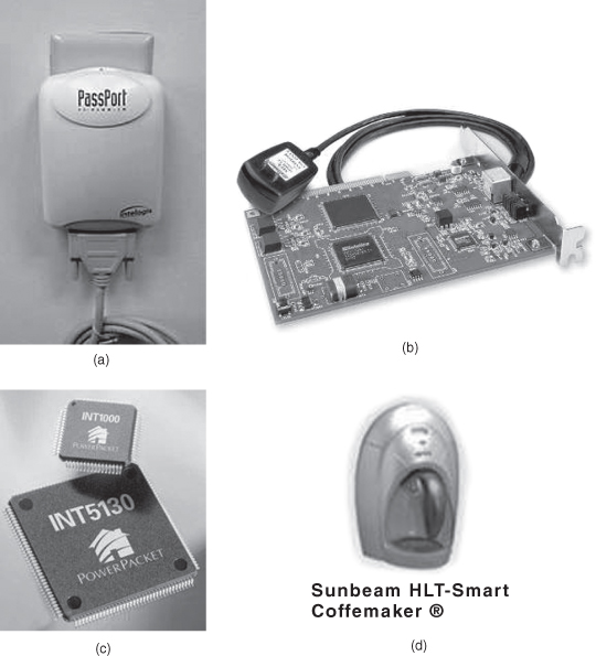
From the viewpoint of customer side applications, PLC is becoming an alternative to existing wireless technology for a seamless in-home network environment where the wireless applications cannot supply consistently stable, high-throughput service. As shown in Figure 11.1a and 11.1b, every PC or peripheral device is attached to PLC connecting outlets or adapters that behave as modems. Figure 11.1c illustrates an integrated power-line MAC/PHY transceiver that requires no new wiring to support transmission at speeds of up to 14 Mbit/s. It provides the ability to interconnect multiple interfaces to the external MAC controller. Figure 11.1d shows a smart coffeemaker that communicates via PLC when it is plugged to an AC outlet and communicates wirelessly via radio frequency (RF) when operated on batteries.
Figure 11.1. Various PLC products: (a) Power-line PC networking connectors. (b) Power-line network adapter. (c) integrated powerline MAC/PHY transceiver. (d) HLT-smart coffeemaker.
11.2.1 Narrowband (NB) PLC
11.2.1.1 Home Control.
Typically, home-control PLC transmitters operate by modulating a carrier wave of between 20 and 200 kHz into the household wiring. The carrier is modulated by digital signals. Receivers may be either plugged into regular power outlets or permanently wired in place. Since the carrier signal may propagate to nearby homes or apartments on the same distribution system, receivers are assigned individual house internet protocol (IP) addresses that identify their owners. Thus receivers can be individually controlled by the signals transmitted over the household wiring.
Real-Time Energy Management Systems As an example of Smart Grid functionalities illustrating the requirements for the communication network, a PLC network is proposed to be a very attractive solution. Assuming that every household is equipped with such a real-time pricing meter, the PLC network between meters and the common transformer station can accommodate thousands of nodes or more. It is therefore essential to enable fast access to individual meters for better quality of service on the customer side [48].
Another application of PLC system in interaction with Smart Grid functionalities is the management of energy distribution using a supervisory control and data acquisition (SCADA) system. SCADA sensors monitor the grid load and forward to its fusion center, where two-way commands adapt the distribution structure to the dynamics of energy generation and consumption. Thus, the SCADA system imposes strong reliability and real-time equipments on PLC.
11.2.1.2 Low-Speed Narrowband Communications.
Narrowband applications of mains communications vary enormously, as would be expected of such a widely available medium. One simple application of narrowband power-line communication is the control and telemetry of electrical equipment such as meters, switches, heaters, and domestic appliances. A number of active developments are considering such applications from a systems point of view, such as demand-side management. Domestic appliances would intelligently coordinate their use of resources like limiting peak loads. Such applications are being developed for the emerging smart grid systems that embrace the PLC technologies.
Meanwhile, control and telemetry applications include both (a) utility-side applications, which utilize equipment belonging to the utility company (i.e., from the supply transformer substation up to the domestic meter), and (b) consumer-side applications, which utilize equipment in the consumer’s premises. Possible utility-side applications include automatic meter reading, dynamic pricing, load management, load profile recording, financial credit control, pre-payment, remote connection, fault detection, and network management, and they could be extended to gas and water control.
It is known that the most robust low-speed power-line technology uses differential code shift keying (DCSK) technology available from Yitran Communications [9]. Renesas Technology licenses this technology from Yitran and incorporates it in the single-chip microcontroller unit (MCU) PLC family of devices known as M16C/6S. Renesas also licenses a state-of-the-art network layer for Automatic Meter Reading/Automated Meter Management (AMR/AMM) applications that can run on these devices [9].
11.2.1.3 High-Speed Narrowband Communications.
Distribution line carrier (DLC) uses existing electrical distribution network mainly in the medium voltage (MV). It is very similar to the powerline carrier. DLC uses NB PLC technology in frequency range of 9–500 kHz with data rate up to 576 kbit/s [10]. DLC is suitable for multiple real-time energy management applications. It can be implemented under the Real-Time Energy Management over Power Lines and Internet (REMPLI) System as well as the Supervisory Control and Data Acquisition (SCADA), AMR, and Power Quality Monitoring System (PQMS) [11]. DLC complies with the standards such as EN 50065 (CENELEC), IEC 61000-3 and FCC Part 15 Subpart B [10].
Apparently, there are no interference issues between DLC and radio users or electromagnetic radiation. With external inductive or capacitive coupling, a distance of 15 km or further can be reached over a medium-voltage network. On low-voltage networks, a direct connection can be made because the DLC has a built-in capacitive coupler. This allows end-to-end communications from substation to the customer premises without repeaters.
Recent DLC systems significantly improve upon and differ from other PLC segments. DLC is mainly useful for a backhaul infrastructure that can be integrated with corporate wide-area networks (WANs) via TCP/IP, serial communication or leased-line modem to support for multiservices real-time energy management systems.
11.2.1.4 Utility Applications.
Most utility companies mainly adopt special coupling capacitors to connect medium frequency (MF) radio transmitters to the power-frequency AC conductors. The active frequency region lies in the range of 24–500 kHz, with transmitter power levels up to hundreds of watts. These signals may be superimposed on one or more conductors of a high-voltage AC transmission line. Multiple PLC channels may be coupled onto one HV line. Filtering devices are applied at substations to prevent the carrier frequency current from being suppressed by the station equipment and to ensure that distant faults do not affect the isolated segments of the PLC system. These circuits are contrived to control switchgear and to protect transmission lines. For example, a protection relay can make use of a PLC reference channel to stay on a line if a fault is detected between its two terminals, but to leave the line in operation if the fault is elsewhere on the system.
While utility companies use microwave and fiber-optic cables for their primary system communication needs, the power-line carrier module may still be useful as a backup channel or for relatively very simple low-cost installations that do not require installing fiber-optic lines.
11.2.2 Broadband PLC
HF communication may reuse large portions of the radio spectrum or may use selected bands, depending on the technology.
11.2.2.1 In-Home Networking.
PLC can be used to interconnect home or office computers, peripheral devices or other networked consumer electronics. As shown in Figure 11.2, a typical application of home networking is the streaming of high-definition (HD) video content through consumer premise equipment (CPE) such as a PC or home server to a HD-TV in the living room.
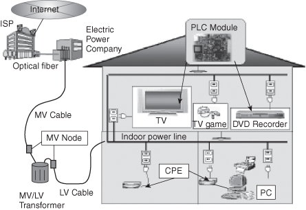
Various wired (e.g., Ethernet, Coax) and wireless networks (e.g., WiFi) exist to establish these home networking functions. However, there might be some drawbacks of these solutions, especially for “room-to-room” connectivity and long distances within the house. The data throughput of wireless connections decreases if the signal is attenuated by walls or ceilings. Wired networks may require inconvenient installation efforts. For mains-powered devices, PLC technology enables new and highly convenient networking functions without any additional cables. An in-home backbone connecting all devices or clusters in the house is provided by PLC, as can be seen in Figure 11.2. Wireless devices can communicate via an access point to the PLC network [12]. Although there is not yet a universal standard for this type of ubiquitous application, standards for power-line home networking are being regulated by numerous companies within the framework of HomePlug Power-Line Alliance (HPA) and the Universal Power-Line Association (UPA) [13].
Today’s PLC solutions theoretically promise data rates up to 200 Mbit/s on physical layer. Measurements in buildings show significant lower bit rates due to high attenuation, frequency-selective transfer functions, and noise in many cases. Typically, today’s PLC systems use one transmit and one receive port for data communication. However, in most parts of the world, three-wire installations allow more feeding and receiving options. In the presence of multiple feeding and receiving ports, MIMO principles can be exploited.
The in-home power-line technology focuses on delivering a short-distance solution. Services like power-line intranet solutions and power-line music distribution (that follow the EN 55022 directive [14]) belong to the in-home networking category. These kinds of services compete against other in-home interconnection technologies such as wireless, even so though the bit rates in wireless connections are definitely lower [15]. In-home power-line technology can also provide services like sending a small amount of data with low bit rate (for example, to open an automatic door or to control the switching on and off of a light).
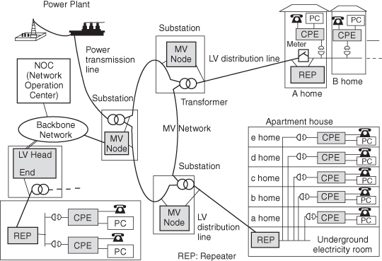
Besides in-door PLC applications, we also have outdoor utility-side applications that have intermediate MV nodes and repeaters (REP) to connect between power-line backbone infrastructure and supply transformer substations (see Figure 11.3). To accommodate multiple consumer premise equipments (CPE) and guarantee reliable transmission of the data or information, we need to insert REP between transformers and CPE.
11.2.2.2 In-Vehicle Networking.
In a similar way as in-home PLC networking, power-line transmission can be applied to in-vehicle networks. In any vehicle (from automobiles to ships, from aircraft to space vehicles), separate cabling is used to establish a broadband physical layer for a local command and control network. The in-vehicle power distribution network may serve as an infrastructure supporting both power delivery and broadband digital connectivity [16].
11.2.2.3 Broadband Internet Access.
Broadband over power lines (BPL) literally provides broadband Internet access through ordinary power lines. A computer or workstation only needs to plug a BPL modem into any outlet within equipped homes or offices to have high-speed Internet access. BPL may offer benefits over regular cable modem or digital subscriber line (DSL) connections. The extensive infrastructure already pre-installed enables people to access the Internet in remote locations without additional equipment costs. Also, such ubiquitous availability would make it easier for hooking up televisions, sound systems, and so on.
PLC modems transmit data signals onto HF electric carriers. The asymmetric speed in the modem is generally from 256 kbit/s (uplink) to 2.7 Mbit/s (downlink). In the repeater, it can be increased up to 45 Mbit/s. Meanwhile, the speed from the head ends to the Internet rises up to 135 Mbit/s, relatively a favorable speed to the end customers.
The PLC system faces a number of challenges. The primary one is that power lines are inherently very noisy. Every time a device turns on or off, it introduces a pop or click into the line. Energy-saving devices often introduce noisy harmonics into the line. The second major issue is the signal strength and operating frequency. The system is expected to operate in frequencies of 10–30 MHz, which has been typically used for decades by amateur radio operators as well as international shortwave broadcasters. Power lines are unshielded and will behave as antennas for the signals they carry, and thus they will experience interference from shortwave radio communications.
Much faster transmissions using microwave frequencies transmitted via a surface wave propagation mechanism have been demonstrated using only a single power-line conductor. These systems have shown the potential for symmetric and full duplex communications in excess of 1 Gbit/s in each direction. Multiple WiFi channels with simultaneous analog television in the 2.4- and 5.3-GHz unlicensed bands have been demonstrated operating over a single MV line. In addition, because it can operate anywhere in the 100-MHz to 10-GHz region, this broadband technology can completely avoid interference issues associated with use of shared spectrum while offering flexibility for modulation and protocols of a microwave system [17].
11.2.3 Modulation Techniques
Modern BPL systems use the Orthogonal Frequency Division Multiplexing (OFDM) technique, which allows customers to mitigate interference with radio waves by removing specific frequencies [17]. The most commonly used transmission methods are single-carrier, spread-spectrum, and OFDM modulation schemes (see Figure 11.4). OFDM is preferred over the two other methods because due to limited spectral resources PLC technology must achieve maximum spectral efficiency. Moreover, implementing high data rates results in the generation of contiguous wideband transmission signals. While spread-spectrum modulation additionally adopts spreading carriers to obtain a widely spread flat spectrum, OFDM achieves multiple narrowband subchannels that are mutually orthogonal.
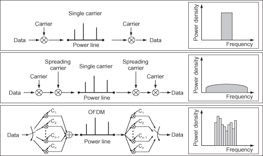
In OFDM techniques, due to the subchannels’ narrowband property, attenuation and group delay are constant within each channel. Thus, equalization is easy and can be performed by only a single tap. Orthogonality of all carriers leads to outstanding spectral efficiency, which has been identified as a key element for the success of high-speed PLC.
11.3 CHANNEL CHARACTERISTICS OF POWER LINES
The development of power-line communication systems requires detailed knowledge of the channel properties, such as transfer function, interference scenario, and channel capacity for choosing suitable transmission methods. This section presents appropriate power-line channel models, which form the basis of a channel emulator that was developed in references 19 and 20. The emulator proved to be helpful for various tests and the comparison of performance of different communication systems. In particular, numerical simulations of power-line channel capacity clearly demonstrate enormous potential of PLC for high-speed communication purposes [18].
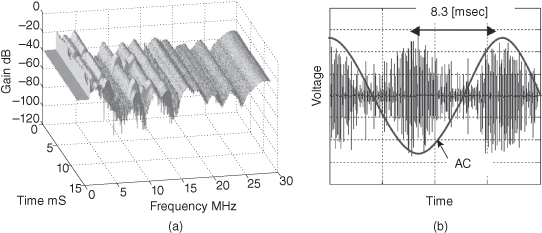
According to measurements, a fundamental property of the power-line channel is that the time-varying behavior is periodic, where the period is typically half the AC mains period (50 or 60 Hz). Parallel to the channel I/O response behavior, the noise statistics exhibit a cyclo-stationary component with the same period. An example of this behavior unique to the power-line channel is shown in Figure 11.5 [19], where we recognize that the power-line channel is time-varying and frequency-selective, and the noise variation has a spectral component of envelope with the period of 8.3 (ms).
Figure 11.5. (a) Measured time variation of indoor power-line channel. (b) Noise waveform generated by the dimmer of a halogen light.
11.3.1 Multipath Channel Model
From a multipath point of view, the signal components of the N individual paths are combined by superposition, and thus the frequency response can be represented in a simplified model as follows [21]:
(11.1)
![]()
where the first, second, and third multipliers are weighting factor, attenuation portion, and delay portion, respectively. The parameters for the multipath echo model above can be obtained from measurements of the complex channel transfer function. The attenuation parameters a0 (offset of attenuation), a1 (increase of attenuation), and k (exponent of attenuation) can be obtained from the magnitude of the frequency response. To determine the path parameters di and gi, the impulse response is necessary. The impulse response gives information about the time delay τi of each path, which is proportional to di. The weighting factors gi can be obtained from the amplitude of each impulse. Typical values for the number of paths N are in the range of 5–50.
11.3.2 Noise
In general, we consider four types of noise components, usually present in the power distribution network: background noise, random impulse noise, synchronous noise, and continuous noise.
Background noise has a smooth spectrum. The most important sources of noise with a smooth spectrum are universal motors—that is, small motors with serial windings. The power spectral density N(f) of this noise type was found to be a decreasing function of the frequency f in the frequency band of interest and on average can be described as follows [22]:
The value of K in (11.2) changes with time and transmitter/receiver locations. However, when compared to the targeted bit rates of 256 kbit/s (uplink) and 2.7 Mbit/s (downlink), K is known to be constant for long periods of time: During the daytime, K normally remains unchanged for many seconds to minutes, whereas at night, often no real changes occur for hours. Although the distribution of measured values for K differs somewhat between locations, a specific type of noise is present more often than in another environment.
Synchronous noise is mainly generated at frequencies synchronous to the power-line base frequency mostly by light dimmers. Silicon-controlled rectifiers triggered by power voltage cause a very short break in current flow. The length of the break determines the intensity of light. Because switching is synchronous to the power frequency, a series of harmonics with various amplitude is generated. The setting of the dimmer and the characteristics of the lamp (bulb) dictate which harmonics carry most power. Usually, harmonics are small compared to fundamental frequency, but the fundamental frequency can also be far below their level. All switching devices operating on a similar principle tend to produce noise spikes synchronous to 50 or 60 Hz.
Another type of noise encountered in the power network is the periodic nonsynchronous noise that is continuous over time. It is generated by television sets and computer monitors. This kind of noise is mainly caused by silicon-controlled rectifiers (SCR), which switch a certain number of times every mains frequency [23]. What results is a train of noise impulses in the time domain, or noise at higher harmonics of the power system frequency in the frequency domain.
The only type of noise that spread spectrum modulation cannot deal with efficiently is white background noise, which is a hybrid of both background and random impulse noise. Its frequency spectrum occupies all the communication bandwidth; therefore extending the signal spectrum does not provide any gain. On the contrary, the noise power increases while (due to numerous factors) the signal power usually has to stay constant. The problem becomes more serious as the main source of white noise is believed to be universal motors, which can be found in many household appliances (electric drill, mixer, coffee grinder, hair dryer, fan, etc.).
11.3.3 Attenuation
The total signal attenuation of the channel consists of two parts: coupling losses and line losses. Coupling losses depend entirely on the design of the transmitter and can in principle be made arbitrarily small. The main subject in this section will, therefore, be line losses—that is, the amount of signal power lost into unwanted directions as a function of distance between transmitter and receiver.
In principle, two receivers are needed to accurately measure the line losses as a function of time and frequency: One receiver measures the received signal power close to the transmitter, and the other at the same time measuries the received signal power at a distance d from the transmitter. Subtraction of the two then cancels possible coupling losses and renders the line losses. However, since only one receiver setup is available, usually the measurements are taken at two well-separated time instances. Although both the received signal power at a distance d from the transmitter and the signal power close to the receiver show large frequency dependencies, the subtraction of the two measurements gives a value of the line losses that is almost frequency-independent. This implies that the frequency dependencies in the received signal are mainly due to variations in the coupling losses.
11.3.4 Electromagnetic Interference (EMI)
Electromagnetic fields radiated from power lines may cause disruption to existing critical radio communication services. To address this issue, research groups have been collaborating with Agilent Technologies in the development of PLC systems with low EMI radiation. Recently, the potential use of optical inductive couplers for broadband power line modems to reduce EMI radiation has been demonstrated. Also, mathematical models are being developed to predict radiated electromagnetic fields from power lines under different cabling arrangements. We expect to develop new signal-injection technologies for suppressing EMI radiation from PLC systems to guard against harmful effect of the radiation [24].
To minimize possible electromagnetic interferences (EMI), PLC access networks have to operate with limited signal power, which in turn may reduce the system data rate. In order to compete with other access technologies, PLC systems have to ensure higher levels of network utilization. A medium access control (MAC) protocol that maximizes network utilization is thus necessary. Both mathematical and simulation models have been successfully developed for MAC protocol performance analysis under impulsive noise interference. Currently, a new protocol is being designed by the IEEE Standardization Group; it is called P1775, which would optimize packet length to achieve maximum network utilization in different PLC environments [25].
11.4 COUPLING TECHNIQUES
The communication signal is modulated on RF signals between an electrical power distribution line and the electrical power wiring at a customer’s premises. This includes (a) a first transceiver for transmitting and receiving electromagnetic energy, which is inductively coupled to the distribution line, and (b) a transceiver for receiving electromagnetic energy from, and transmitting electromagnetic energy to, the first transceiver. The second transceiver is coupled to the customer’s power wiring to receive communication signals from, and to supply communication signals to, the customer’s power wiring [26].
11.4.1 Capacitive Coupling and Inductive Coupling
Once the data signal has been generated, it needs to be placed on the power line by some kind of coupling network. The idea is to superimpose the data signal onto the 240-V, 50-Hz (or 110-V, 60-Hz) power waveform and extract it afterwards at the receiving end. There are three possible combinations of lines on which to couple the signal: live to ground, neutral to live, and neutral to ground. Differential mode coupling is a scheme where the live wire is used as one terminal which the neutral is used as the other. In the case where a neutral line is not present, the ground line acts as the second terminal. Common mode coupling involves the live and neutral being treated as one terminal, with the ground being treated as the other. This kind of coupling is potentially not safe, and hence it is not used.
For coupler implementation, differential mode coupling is often used. The basic component used for the coupling may be capacitive or inductive [27].
An inductive coupler is a kernel component that transmits only PLC signals between the power line and the PLC data transceiver. It is quick and easy to install without connecting the communication cable to the power line because it is clamped around power line. The PLC signal can be transmitted a to power line with low signal loss for a wide frequency range. In fact, an inductive coupler provides more benefits when compared with a capacitive coupler. It can be applied to low- and high-speed PLC application regardless of voltage, and it can be applied to PLC application such as an automation of electric power distribution system, power line monitoring system, home network, automatic meter recording (AMR), and ship network, among others [28].
For a prototype implementation of the system we are trying to establish simple communication between two data communication equipments. Thus we need two couplers of different frequency responses, one in the transmit direction and the other in the receive direction. At the receiver side the coupling device should possess a band-pass characteristic, blocking the 50-Hz mains voltage and passing signal at the carrier frequency. At the transmitter side, the coupler should possess high-pass properties, passing the communication signal unattenuated. The coupler should also be impedance-matched to the power line for maximum power transfer [29].
11.4.2 Mitigation of Inductive Interference
Electric power systems, like almost everything run by electricity, depend on internal electric and magnetic fields; some of these fields are affected by the surrounding environment. The strongest of these fields can then induce voltages and currents in nearby devices and equipment and, in some cases, can interfere with the internal fields being used by electrical equipment in the vicinity. These induced voltages and currents, which are due to the coupling between the energized source and the electrical equipment, are called inductive interference [30].
Overhead power lines cause practically all of the problems due to inductive coupling. For this reason and for safety considerations, power lines are built in special corridors far from inhabited areas. Spacing between them and the requirements of their surroundings are considered and carefully calculated to minimize possible interference. These are often shared by telephone lines, communication circuits, railroads, and sometimes trolley buses, each of which must be considered for possible inductive coupling.
Modern telephone and communication circuits are well-shielded and rarely encounter interference from nearby power lines. However, where a long parallel exposure exists, inductive coupling can be reduced by balancing the operation of the power line—that is, by simultaneously transporting power and data signals. Fences, long irrigation pipes, and large underground objects within the corridors may experience considerable inductive coupling and must be grounded for safety [31].
11.5 STANDARDS
Despite numerous advantages in broadband over power lines (BPL) connectivity to and within the home, the fundamental obstacle for adopting this technology is the lack of an international technical standard issued by a credible and globally recognized standards-setting body [32]. The first standard for PLC applications is the European CENELEC EN 50065 regulated in 1991, which mandates the use of the frequency range between 3 kHz and 148.5 kHz [33]. Since then, much effort has been made to regulate the standards and enlarge the practices of consumer premise equipments. We expect that most of technical challenge will be overcome soon through the work of the IEEE P1901 Corporate Standards Working Group [34].
11.6 PRACTICAL EXAMPLE
The power-line channel is time-varying due to the appliances connected to outlets. Appliances often exhibit input impedance that is a function of the instantaneous amplitude of the mains voltage which results in a periodically time-varying channel response. Here we explore a discrete time-varying block channel model in the time domain [35], which allows for more realistic evaluation of modulation and coding strategies as well as for the design of bit loading strategies that can be resilient to the particular type of distortion in this harsh medium. Block transmission is a very efficient scheme to combat intersymbol interference (ISI) caused by frequency-selective time-dispersive channels at the cost of interblock interference (IBI) occurring during block transmission. In particular, in order to suppress the IBI in the power-line communication channel, a novel method called the lifting-trailing-zeros (LTZ) technique is introduced in Section 11.6.1.2. We also propose a power-line network simulator and demonstrate its effectiveness by numerical verification.
11.6.1 System Model
11.6.1.1 Discrete-Time Block Model for Time-Varying System.
Let us define the output samples y[k] := y(kTs) with symbol duration Ts. Then, a single-input single-output (SISO) time-varying system can be represented as
where the time-varying impulse response is 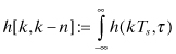 p((k−n)Ts−τ) dτ and p(t) is a
pulse shaping filter with a Nyquist characteristic.
p((k−n)Ts−τ) dτ and p(t) is a
pulse shaping filter with a Nyquist characteristic.
In (11.3) we find the well-known fact that for a linear time-invariant (LTI) system, the effective discrete-time impulse response is
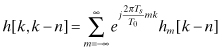
where hm[k] is the discrete-time impulse response of the mth lag at time k. This leads to writing the output as well as a sum of components:
(11.5)
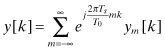
where ym[k] is the discrete-time output response of the mth lag at time k [35].
11.6.1.2 Lifting.
The technique we use parses the data in blocks of size P bigger than the maximum memory of the discrete-time equivalent system L. The objective is to account explicitly for interblock (IBI) interference while hiding the parameters that cause the intersymbol interference (ISI) inside the mixing matrices that map input blocks into output blocks. The rationale behind the assumptions that the blocks are large enough and the system is causal is that only the previous block will interfere with the current block, allowing us to describe the input–output relationship in a compact form.
For a length-P block, let us define the ith block as follows:
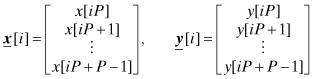
Then, (11.3) becomes
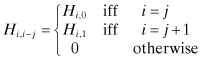
where the channel transformation matrices Hi,i−j are of size p × p and their (k,n)th element is defined as
If the system is linear time-invariant (LTI), then (11.7) can be represented as
where the (k,n)th element of Hi−j is defined as follows:
(11.10)
![]()
The following lemma is proved in reference 35.
If the channel memory L (i.e., L + 1 taps) is finite and L < P, then Hi,i−j is nonzero only for i − j = 0,1, that is,
(11.11)
Thus (11.7) becomes
while (11.9) becomes
where Hi,0 and Hi,1 are band lower-triangular and upper-triangular, respectively, and H0 and H1 are both Toeplitz.
From Lemma 11.1, a useful corollary follows.
COROLLARY 11.2
If x[i] has L trailing zeros, where L is the channel memory, then for all i we obtain Hi,1x[i − 1] = 0 and hence (11.12) and (11.13) are simplified to
(11.14)
![]()
(11.15)
![]()
The corollary allows us to describe the cascade of N linear systems recursively, as described by the following Theorem.
THEOREM 11.3
Let us consider a cascade of N linear systems. If the memory of the ith system is finite and equal to Li, then the memory of the cascade of all N linear systems is equal to ![]() .
.
Now, choosing P ≥ L(1,…,N), we can apply Lemma 11.1 and obtain
(11.16)
![]()
where ![]() is still
band lower-triangular while
is still
band lower-triangular while ![]() is
upper-triangular.
is
upper-triangular.
11.6.1.3 Transmission Lines (TL) as Two-Port Networks (2PN).
In TL theory, a common way to represent a two-port network (see Figure 11.6) is to use the transmission matrix, also known as the ABCD matrix [36].
In TL theory the relationship between current and voltage in frequency domain at the two ports of a 2PN is given by
where the quantities above are all complex phasors. This
description can be easily mapped into an overall system transfer function. Let us
consider load impedance ![]() constant in
time and frequency with a closed output port, a generator transmitting a signal with
Fourier transform Vs(f), and source impedance
constant in
time and frequency with a closed output port, a generator transmitting a signal with
Fourier transform Vs(f), and source impedance ![]() constant in time and frequency. Then we can represent (11.17) as
follows:
constant in time and frequency. Then we can represent (11.17) as
follows:
Figure 11.6. Frequency domain representation of a two-port network (2PN).
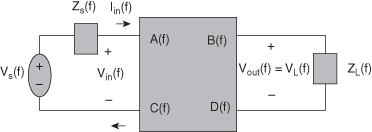
The above expressions show that the effects of the ABCD parameters in (11.17) for voltage and current phasors can also be interpreted as a filtered version of the input voltage and current signals.
In general, a power line point-to-point link consists of several sections of power cables including bridged taps. The end-to-end system can be decomposed in the cascade of several subsystems, and each subsystem can be modeled with an appropriate 2PN. By a well-known Chain Rule, we can obtain the overall channel transmission matrix by simply multiplying the transmission matrices of each subsystem.
In the case of a time-varying system, expressions (11.18) and (11.19) do not hold. Nevertheless, the relations between current and voltage remain linear and, as such, one can still express the dependency of the output voltage as functions of the input voltage, the input current, and the output current via the following integral relationships:
(11.20)
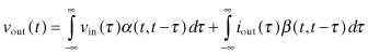
(11.21)
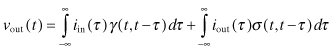
where α[t, t − τ], β[t, t − τ], γ[t, t − τ], σ[t, t −
τ] are defined as the time-varying inverse Fourier
transform pairs of ![]() , respectively. We
can represent each of the above continuous time convolutions by their discrete-time
equivalent similarly as done in Section 11.6.1.1 and write the following
discrete-time model:
, respectively. We
can represent each of the above continuous time convolutions by their discrete-time
equivalent similarly as done in Section 11.6.1.1 and write the following
discrete-time model:
where α[k, k − n], β[k, k − n], γ[k, k − n], and σ[k, k − n] are defined as in (11.4).
The relationship between source and load voltages and the output voltage and current can also be easily expressed in the discrete time:
(11.24)
![]()
(11.25)
![]()
Let us define vs[i], vout[i], vin[i], iout[i], and iin[i] in an analogous manner as in (11.6). Then if the system memory is finite and L < P, then (11.22) and (11.23) can be cast in their lifted form as follows [20]:
where Ai,0 (and Bi,0, Ci,0, Di,0) is defined similarly as in (11.8),
(11.30)
![]()
Using these block matrices which are band lower-triangular for the current input blocks and upper-triangular for the previous blocks, we are able to remove the interblock interference (IBI) terms via the lifted-trailing-zeros (LTZ) technique and find a simplified input–output (I/O) relationship in two-port network topology. Once we obtain a closed form of I/O relationship for adjacent front-end pairs, we apply it to multiple segments of power-line cable in a cascaded manner and find the overall I/O relationship.
11.6.1.4 Transmission Line I/O Relationship in the DT Case.
For the continuous-time channel impulse response h(1,…,N)(t, τ) of the 2PN, we can write the following input–output relationship
(11.31)
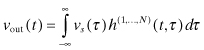
and this maps to the discrete-time equivalent relationship
(11.32)
![]()
Our objective is to calculate the lifted form ![]() corresponding to h(1,…,N)[k, k − n]
corresponding to h(1,…,N)[k, k − n]
(11.33)
![]()
In order to do this, we first tackle the single system case and then we extend our results to the cascade of multiple systems.
There are various ways to find the input–output (I/O) relationship in the single system case. First, based on Lemma 11.1, we can prove the following theorem.
THEOREM 11.4
Given a system with finite memory L < P, the input–output relationship in terms of vout[i], vs[i] and vin[i] is given by the expression
(11.34)
![]()
where we introduce newlydefined block matrices as follows:
(11.36)
![]()
(11.37)
![]()
(11.38)
![]()
Since block matrices Ai,0 and Ci,0 are band lower-triangular and full rank, thus they are invertible. Hence we only need to check the invertibility of Gi,0 in (11.35).
COROLLARY 11.5
Under the assumption of trailing zeros, i.e. forcing the last L input symbols to be zeros, then the input–output relationship between vs[i] and vout[i] is
(11.39)
![]()
If Gi,0 is invertible, then the channel
transformation matrix Hi,0 is
![]() , otherwise Hi,0 is given by the
pseudo-inverse matrix
, otherwise Hi,0 is given by the
pseudo-inverse matrix ![]() .
.
11.6.2 Implementation of PLC Network
11.6.2.1 Overall Power Line Network Simulator.
Using the lifted forms for the relationship between source and load voltages and the output voltage and current in (11.26)–(11.29), we find a generalized network simulator which is suitable for cascading time-varying transmission line segments.
For a P-length source voltage vector vs[i] in (11.28), we introduce an M-length symbol vector s[i] via a selected precoding matrix Fl (l is channel memory) as follows:
Let us construct s[i] = [sT[i]···[sT[i + K − 1]]T and ![]() for
K sufficiently large, which result from lifting
s[i] and vs[i] twice.
Assuming that the channel memory is finite, similarly to (11.12)
the equation (11.40) simplifies to two terms.
for
K sufficiently large, which result from lifting
s[i] and vs[i] twice.
Assuming that the channel memory is finite, similarly to (11.12)
the equation (11.40) simplifies to two terms.
(11.41)
![]()
where ![]() 0 multiplies the
current input vector and
0 multiplies the
current input vector and ![]() 1 multiplies the
past (IBI) term.
1 multiplies the
past (IBI) term.
![]() 0 and
0 and ![]() 1 are block matrices of size KP-by-KM. Blocks of
1 are block matrices of size KP-by-KM. Blocks of ![]() 0 are band lower-triangular matrices. Blocks of
0 are band lower-triangular matrices. Blocks of ![]() 1 are upper-triangular matrices with few
nonzero elements in their upper-right corners. Then, (11.26)–(11.29) can be rewritten with IBI terms in doubly lifted forms as
follows:
1 are upper-triangular matrices with few
nonzero elements in their upper-right corners. Then, (11.26)–(11.29) can be rewritten with IBI terms in doubly lifted forms as
follows:
(11.42)
![]()
(11.43)
![]()
(11.44)
![]()
(11.45)
![]()
where we have defined
In addition, ![]() ,
, ![]() are block matrices and
are block matrices and ![]() i,k,
i,k, ![]() i,k,
i,k, ![]() i,k,
i,k, ![]() i,k (k = 0,1) have similar structures as
i,k (k = 0,1) have similar structures as ![]() 0 and
0 and ![]() 1, except
that they are of size KP-by-KP.
1, except
that they are of size KP-by-KP.
Now we consider designing a two-port power line network simulator via iterative updates. As shown in (11.46)–(11.49), all IBI terms are determined by the past values. If the two-port network is activated at rest, we can arrange the system equation (or equivalently, its symbolic representation) as follows:
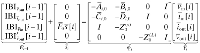
where ![]() i−1 is determined from the input current and
voltage vectors in the previous block at the first stage and the current vector in
the previous block at the last stage.
i−1 is determined from the input current and
voltage vectors in the previous block at the first stage and the current vector in
the previous block at the last stage.
In particular, since ![]() is
nonsingular in (11.50), we obtain the generalized I/O relationship between
is
nonsingular in (11.50), we obtain the generalized I/O relationship between ![]() i and
i and ![]() i as follows:
i as follows:
where ![]() is
invertible if block matrices
is
invertible if block matrices ![]() i,0,
i,0, ![]() i,0,
i,0, ![]() i,0, and
i,0, and ![]() i,0
are full rank. The relation (11.51) forms a basis for the PLC network
simulations used in Section 11.6.2.3.
i,0
are full rank. The relation (11.51) forms a basis for the PLC network
simulations used in Section 11.6.2.3.
11.6.2.2 Bistatic Load Impedances and Channel Capacity.
Let us now consider the case of switched impedances. We can approximate the transition between the two responses as instantaneous and decompose the time-varying load impedance Z(t,f) into the sum of two alternating contributions characterized by the locally time-invariant base-band equivalent impedances Z1(f), and Z2(f) as follows:
(11.52)
![]()
where
![]()
We also have that if the eigenvalue decomposition (EVD) of input
covariance matrix is ![]() , the maximum
information rate per ith block can be expressed as
, the maximum
information rate per ith block can be expressed as
(11.53)
![]()
where λmm(i) are eigenvalues with {λ[i]}m,k = δ[m − k]λmm(i), ϕmm(i) are power constraints,
and ![]() ,
, ![]() ≤ P, is the number of nonzero eigenvalues.
≤ P, is the number of nonzero eigenvalues.
In addition, when ϕmm(i) equal to the FCC constraints, ϕmm(i) = FCCm, by averaging over the two channel frequency responses T1(fm) and T2(fm), we obtain the total achievable average channel capacity C(TOT) as
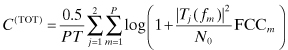
where Tj(fm) (j = 1, 2) is one of the two transfer functions for the mth symbol block.
11.6.2.3 Numerical Results.
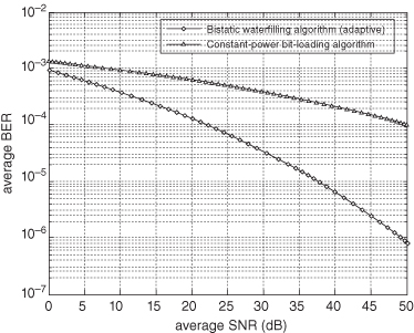
Figure 11.7 illustrates a simple model with two appliances, where each of them has a time-varying characteristic of high impedance for half of the AC cycle and low impedance for the other half. The actual values of the transfer functions are calculated using the PLC model given in reference 4. We want to compare C(TOT) for two schemes; one is the bistatic capacity with waterfilling (power loading [37]) proposed in this section, and the other is the constant-power bit-loading capacity (as commercial modems do now). The achievable capacity in the band 2–30 MHz for bistatic channels is obtained by (11.54). In Figure 11.8, the bistatic waterfilling capacity is compared with constant-power bit-loading capacity. Figure 11.9 illustrates the behavior of the two schemes in terms of average bit error rate (BER) versus average received SNR for a fixed target BER of Pe = 10−3. The uniform-power bit-loading scheme has a simpler structure but slow convergence, while the adaptive waterfilling scheme exhibits relatively faster convergence. It is seen from Figure 11.8 and 11.9 that the bistatic algorithm exhibits better performance than the constant power bit-loading algorithm.
Figure 11.7. Schematic diagram of (a) a simple model and (b) its corresponding transfer functions.
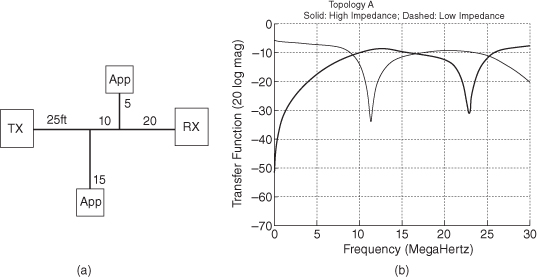
Figure 11.8. Comparison between bistatic channel capacity and constant power loading capacity over various SNR (dB).
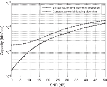
Figure 11.9. Comparison between constant-power bit-loading and adaptive water-filling algorithms with target Pe = 10−3.
The example we have discussed shows that a power-line block transmission model over time-varying channels is useful to find the characteristics of the entire PLC network topology. The examples also show that the PLC technology can provide high-capacity and low-BER performances. Thus the PLC technology is a good candidate for inclusion in the smart grids that are described next.
11.7 SMART GRID SYSTEMS
A smart grid can achieve the increased utilization of capital assets while minimizing operations and maintenance costs. Optimized power flows reduce waste of high-cost generation resources and maximize use of low-cost generation resources. Harmonizing local distribution with cross-regional energy flows and transmission traffic improves the use of existing grid resources and reduces grid congestion and bottlenecks, which can ultimately produce consumer savings.
11.7.1 Features
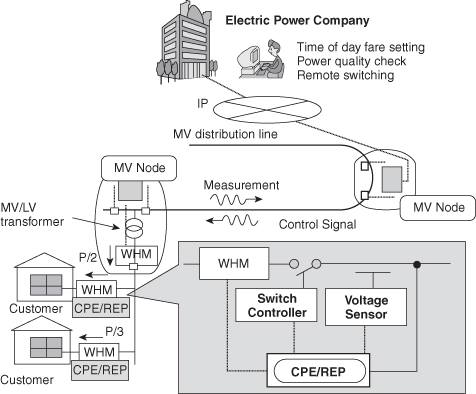
Today existing and planned implementations of smart grids provide a wide range of features including the PLC technology. As illustrated in Figure 11.10 [16], the PLC technology can be directly applied to smart grid system. For example, automated meter reading (AMR) and automated meter management (AMM) via power lines can be easily incorporated. In cooperation with consumer premise equipments (CPE) and repeaters (REP), WebHost Manager (WHM) controls the flow of raw MV level powers before reaching customer premises. It also feeds back the measurement information to MV node and eventually electric power company, which operates daytime fare setting, power quality check, and remote switching.
11.7.1.1 Load Adjustment.
Total load connected to the power grid can vary significantly over time. Total load is the aggregate of individual loads, thus it is not guaranteed to be stable or slow-varying. Using mathematical prediction algorithms, it is possible to predict how many standby generators need to be used, and hence to overcome a certain failure rate. In a smart grid, the load reduction by even a small portion of the clients may resolve the problem of fast-varying loads without the need for large number of additional standby generators.
11.7.1.2 Demand Response Support.
Demand response support [38], enables generators and loads to automatically interact in real time, coordinating the demand to flatten power demand spikes. Eliminating the fraction of demand that occurs in these spikes lowers the cost for additional reserve generators, extends the life of equipment, and allows users to cut their energy bills by notifying low-priority devices to use energy only when it is cheapest. Current power grid systems have varying degrees of communication within control systems for their high value resources, such as generating plants, transmission lines, substations, and major energy users.
11.7.1.3 Distributed Power Generalization.
Distributed power generation in terms of fault tolerance of smart grids allows individual consumers to generate power on the spot, using whatever generation method they find appropriate. This allows individual loads to fit their generation directly to their load, making them independent from grid power failures. Early grids were designed for one-directional flow of electricity, but if a local subnetwork generates more power than it is consuming, the reverse flow can cause safety and reliability issues. Smart grid solutions are being developed to cope with these issues.
11.7.2 Technology
Many smart grid technologies are already used in other applications such as manufacturing and telecommunications and are being adapted for use in grid operations. In general, smart grid technology can be grouped into five key categories [39].
11.7.2.1 Integration of Communications.
Plenty of communication technologies have been developed over time but have not been fully integrated. In most cases, data are being collected via modem rather than direct network connection. Room for improvement lies in substation automation, demand response, distribution automation, supervisory control and data acquisition, energy management systems, power-line carrier communications, fiber-optics, and so on [40]. Integrating several types of communications technologies will allow for the following: real-time control; information and data exchange to optimize system reliability; resource utilization; and security issue.
11.7.2.2 Sensing and Measurement.
In the area of sensing and measurement, important tasks are evaluating congestion and grid stability, monitoring equipment health, preventing energy theft, and supporting control strategies. Such technologies include: advanced microprocessor meters (smart meter) and meter reading equipment, wide-area monitoring systems, online readings by distributed temperature sensing, real-time thermal rating (RTTR) systems, electromagnetic signature measurement/analysis, real-time pricing tools, advanced switches and cables, backscatter radio technology, and digital protective relays [41].
11.7.2.3 Smart Meters.
In a smart grid system, digital meters that record usage in real time are substituting analog mechanical meters. Smart meters are similar to advanced metering infrastructure meters and provide a communication path extending from generation plants to electrical and other smart grid-embedded devices. Such devices can be shut down according to customer preference during times of peak demand [42].
11.7.2.4 Phasor Measurement Units (PMU).
It has been believed that high-speed sensors distributed throughout the electrical supply network can be used to monitor power quality and automatically control the state of the network. Phasors represent the waveforms of alternating current, which are identical everywhere on the network. In the 1980s, the clock pulses from Global Positioning System (GPS) satellites were used for precise time measurements in the grid. Thanks to the ability to record phases of alternating current everywhere on the grid, automated systems are expected to facilitate the management of power systems by responding to system conditions in a rapid, dynamic manner.
11.7.2.5 Wide-Area Measurement System (WAMS).
A Wide-Area Measurement System (WAMS) is a smart network of PMUs that can perform real-time monitoring on a regional and national scale. Most research scientists in the power systems areas believe that the Northeast blackout of 2003 would have been limited to the smaller region if a wide-area phasor measurement network was in place [39].
11.7.3 Applications
Smart grid communications solutions are crucial to building an integrated intelligent grid. High-performance smart grid applications require two-way communications in real-time between centralized fusion center and a number of smart devices throughout the electrical network.
As a practical example, BPL Global offers a variety of smart grid communications solutions such as fiber, wireless, broadband over power line, WiMax, GPRS, Ethernet, radio, and other communication technologies [43]. The broadband over power-line network technology can be utilized in combination with a utility fiber or Ethernet communications infrastructure. In addition to designing and building smart grid communications networks, BPL Global provides full communications and electrical network monitoring and management tools to ensure high quality of service (QoS), cost-effective operations, and effective monitoring management of the smart grid.
Open architecture described in Figure 11.10 enables all smart grid applications to be supported through one common communications network. The reliability of the communications network is essential because this is the backbone for smart grid applications deployed by the utility company [38,43].
11.7.4 From Smart Grids to Energy Internet
Achieving secure and reliable delivery of energy is essential to modern society, but is very challenging due to increasing demand and declining resources. The ongoing effort to restructure the current delivery infrastructure is to improve its performance so that energy can be utilized with higher efficiency. Smart grids have a number of unique features compared to their predecessors: (a) detecting and correcting power flow problems at their very early stage, (b) receiving and responding to broader range of information, (c) possessing rapid recovery capability, (d) adapting to changes and self-reconfiguring accordingly, (e) building in reliability and security from design, and (f) providing operators advanced visualization tools [44–46].
Emerging smart grids start to resemble the Internet system and hence have become known as Energy Internet. Apparent benefits from energy internet are its openness, robustness and reliability. The availability of resources determines that massive generation of energy, such as electricity, has to be centralized. While customers are highly distributed, an extremely sophisticated transmission and distribution network is needed for energy delivery. The challenge is that our current knowledge about complex systems like the electric power grid does not enable us to regulate it efficiently and reliably. Often a compromise has to be made between efficiency and reliability. Consumers will have higher expectations for the service, both for quality and quantity. On the other hand, resources are limited. Hence, generating and saving the energy at the same time will be the main target to satisfy both efficiency and reliability.
11.7.5 Interoperability of Smart Grids through Standards
While there are existing standards for Smart Grid technology that should be used (e.g., distributed generation, metering standards, communications standards), new standards will have to be developed for new interfaces [47]. These include interfaces from the generation sources to the equipment back at the homes and businesses that will need to communicate through the grid, to real-time systems for energy transmission, storage, billing, load balancing, and so on. Therein, interoperability through standards will be the key to making plug-and-play capabilities and to driving down the costs of the various hardware and software systems.
11.7.6 Electric Vehicle Interconnection with Smart Grids
Renewable energy sources have a problem of variability or intermittency, and means of storage are needed to ensure the stability of the grid [47]. Batteries are one appropriate solution. Another possibility that could address both transportation requirements and energy management would be the advent of widespread deployment of plug-in electric or plug-in hybrid electric vehicles.
Electric vehicles, if connected to smart grid, could provide additional non-transportation functionality (e.g., a distributed energy storage medium), which could help in load regulation. A variety of activities need to be done so that vehicle to grid interconnection becomes a reality. First of all, hardware requirements need to be defined for the vehicle and grid interfaces. Secondly, requirements for communications, metering, and billing need to be identified. Finally, utility contracts have to be in place to make use of any capabilities for optimizing two-way electricity flows.
11.7.7 Promises of Future Smart Grids
Future electric power grid is expected to be very different from what it is today. It has to accommodate a large number of renewable generators whose outputs are intermittent and stochastic. Consumer demand will also be stochastic due to demand response programs, smart meters, and intelligent appliances. Extensive deployment of high-resolution sensors and high-speed sensor networks will provide time-synchronous measurements in milliseconds, thus enabling better control of the power grid. However, more research will be needed to understand a new paradigm for the power system operation of future smart grid.
11.8 CONCLUSIONS
Today we have a better understanding of the power-line channel. For practical, promising PLC-smart grid systems, grounding and wiring practices should be further exploited for transceiver optimization. Harmonization of standards and regulations can make analysis of signal transmission more focused.
The innovation potential for PLC is enormous, creating considerable economic values, from which, due to the nature of the powerline medium, everybody may benefit. Toward this goal, it is a primary intention of this chapter to help evaluate the promises and limitations of PLC with respect to everyone’s individual needs. For a clear and complete illustration of the various facets of PLC, recent results and challenges in terms of industry practices and theoretical analysis are presented in order to prepare the potential user for this emerging technology.
Smart grid technology is being recognized as a key solution to challenges such as increasing electric demand and the environmental impact of greenhouse gases produced during electric generation. Integrated smart grid solutions combine advanced sensing technology, two-way high-speed communications and home energy management solutions to provide enhanced services for the endusers.
In addition, the energy Internet is emerging as an implementation of smart grids. It will provide openness, robustness, and reliability. Building an Internet type of energy network for the future will help to resolve some of the pressing energy challenges. Advances in information technology and ongoing research on power infrastructure and complex system will make this goal achievable.
ACKNOWLEDGMENT
I thank Dr. Adam Bojanczyk, Professor of Electrical and Computer Engineering at Cornell University and Dr. Ki-Il Kim, Professor of Department of Informatics at Gyeongsang National University, Korea, for their valuable and helpful comments during reviewing and proofreading of this chapter.
REFERENCES
1. K. Dostert, Powerline Communications, Prentice-Hall, Upper Saddle River, NJ, 2001.
2. H. Hrasnica, A. Haidine, and R. Lehnert, Broadband Powerline Communications: Network Design, John Wiley & Sons, Hoboken; NJ, 2004.
3. S. Barmada, A. Musolino, and M. Raugi, Innovative model for time-varying power line communication channel response evaluation, IEEE J. Sel. Areas Commun, Vol. 24, No. 7, pp. 1317–1326, July 2006.
4. S. Galli and T. Banwell, A novel approach to the modeling of the indoor power line channel—Part II: Transfer function and its properties, IEEE Trans. Power Delivery, Vol. 20, No. 3, pp. 1869–1878, July 2005.
5. F. Corripio, J. Arrabal, L. Del Rio, and J. Munoz, Analysis of the cyclic short-term variation of indoor power line channels, IEEE J. Sel. Areas Commun, Vol. 24, No. 7, pp. 1327–1338, July 2006.
6. K. Dostert, Telecommunications over the power distribution grid—possibilities and limitations, in IEEE International Symposium on Power Line Communications and Its Applications (ISPLC’97), Germany, 1997.
7. http://en.wikipedia.org/wiki/Power_line_communication.
8. http://en.kioskea.net/contents/cpl/cpl-intro.php3.
9. http://www.yitran.com/index.aspx?id=3387.
10. http://www.powerq.com.my/telecommunication/distribution-line-carrier-system.
11. G. Hamoud, R. L. Chen, and I. Bradley, Risk assessment of power systems SCADA, in IEEE Power Engineering Society General Meeting, July 2003.
12. D. Schneider, L. Stadelmeier, J. Speidel, and D. Schill, Precoded spatial multiplexing MIMO for inhome power line communications, in IEEE Global Telecommunications Conference (GLOBECOM’08), New Orleans, 2008.
13. http://www.tgdaily.com/content/view/24994/103/.
14. E. Mainardi and M. Bonfè Powerline communication in home-building automation systems, J. Robotics Automation in Construction, 2008.
15. Y. Lin, A. Latchman, and R. E. Newman, A comparative performance study of wireless and power line networks, IEEE Communi. Mag., Vol. 41, No. 4, pp. 54–63, April 2003.
16. www.argreenhouse.com/papers/sgalli/Sapienza06_PLC.pps.
17. Z. Mingyue, L. Chunying, and B. Haiying, Study of Channel Characteristics of Power Line Communications Networks, in Proceeding Parallel and Distributed Computing Applications and Technologies (PDCAT’05), 2005.
18. M. Gotz, M. Rapp, and K. Dostert, Power line channel characteristics and their effect on communications system design, IEEE Communi. Mag., Vol. 42, No. 4, pp. 78–86, April 2004.
19. T. Sung, Innovative PLC network design for bit loading algorithm and bistatic channel capacity, IEEE International Symposium on Consumer Electronics (ISCE’09), Kyoto, Japan, May 2009.
20. T. Sung, Weighted OFDM and MDFB over time-Varying power line block transmission models, in IEEE International Conference on Signal Processing System (ICSPS’09), Singapore, May 2009.
21. M. Zimmermann and K. Dostert, A multipath model for the powerline channel, IEEE Trans. Commun., Vol. 50, No. 4, pp. 553–559, April 2002.
22. S. Jung, A channel model for power line communication in home network, in Proceeding CISL, February 2002.
24. http://www3.ntu.edu.sg/ntrc/Research_2.htm.
25. http://grouper.ieee.org/groups/bpl/index.html.
26. www.patentstorm.us/patents/7286812/description.html.
28. http://www.mattrone.com/eng/inductive%20coupler.html.
29. http://gomponent.hobbyist.de/ac-coupling/plcc.pdf.
30. M. Yuichiro and K. Toru, Inductive coupling unit and bypass tool for power line communications, J. Mitsubishi Electricity Adv., Vol. 109, pp. 18–20, 2005.
31. http://www.answers.com/topic/inductive-coordination.
32. S. Galli and O. Logvinov, Recent developments in the standardization of power line communications within the IEEE, IEEE Communi. Mag., Vol. 46, No. 7, pp. 64–71, July 2008.
33. www.echelon.com/support/documentation/datashts/153x0.pdf.
34. http://grouper.ieee.org/groups/1901/index.html.
35. T. Sung, A. Scaglione, and S. Galli, Time-varying power line block transmission models over doubly selective channels, in IEEE International Symposium on Power Line Communications and Its Applications (ISPLC’08), Jeju island, Korea, April 2008.
36. E. Biglieri, S. Galli, Y. Lee, H. Poor, and A. Han Vinck, Power line communications, Guest Editorial for the Special Issue on PLC, IEEE J. Sel. Areas Commun, Vol. 24, No. 7, pp. 1261–1266, July 2006.
37. T. Cover and J. Thomas, Elements of Information Theory, John Wiley & Sons, Hoboken, NJ, 2006.
39. http://en.wikipedia.org/wiki/Smart_grid.
40. http://thegreenbutton.com/blogs/chris_blog/archive/2008/05/13/262489.aspx.
41. http://tdworld.com/test_monitor_control/highlights/lios-middle-east-technology-0109.
42. http://www.smarthomeusa.com/info/UPB/about/.
43. http://www.bplglobal.net/eng/markets/index.aspx.
44. L. H. Tsoukalas and R. Gao, From smart grids to an energy internet: assumptions, architectures and requirements, DRPT 2008 IEEE International Conference, Nanjing, China, April 2008.
45. European Commission, Vision for Europe’s electricity networks of the future, European Smart-Grids Technology Platform, EUR 22040, 2006.
46. San Diego Smart Grid Study Final Report, Energy Policy Initiatives Center (EPIC), October 2006.
47. R. DeBlasio and C. Tom, Standards for the smart grid, in IEEE Energy 2030, Atlanta, GA, November 2008.
48 G. Bumiller, L. Lampe, and H. Hrasnica, Power Line Communication Networks for Large-Scale Control and Automation Systems, IEEE Communication Magazine, Vol. 48, No. 4, pp. 106–113, April 2010.