Part III: WIRELESS TECHNOLOGIES AND SPECTRUM MANAGEMENT
12
SIGNALING FOR MULTIMEDIA CONFERENCING IN 4G: ARCHITECTURE, EVALUATION, AND ISSUES
The fourth-generation wireless system (4G) is seen as an integration and an evolution of existing wireless network architecture such as 2G and 3G, with new ones such as mobile ad hoc networks (MANETs). One major issue in 4G is the provisioning of ubiquitous and seamless service access with different underlying wireless technologies. Multimedia conferencing is seen as a service that can enable many “killer” applications such as audio/video conferencing, gaming, and public debating in 4G. In this chapter, we discuss an important technical aspect of conferencing: signaling. It refers to session establishment, modification, and termination. It is indispensable and critical for each phase of conferencing. We will focus on the signaling architectures in 4G (including 3G network, MANETs, and integrated MANETs/3G), and we analyze the signaling performance, the issues, and some solutions.
This chapter consists of three sections. In Section 12.1, we introduce the background information and the state of the art. The concepts of 4G, MANETs, conferencing, and signaling are presented in that section. Section 12.2 is devoted to signaling architectures in 4G. In Section 12.3, we will discuss some signaling performance issues and present a solution that is based on cross-layer design.
12.1 BACKGROUND: 4G, MOBILE AD HOC NETWORKS, AND CONFERENCING
In this section, background information that helps to understand the signaling for conferencing in 4G is provided. We start by introducing the definition and research challenges of 4G. As the new network component in 4G, the concept, classification, and technologies of mobile ad hoc network (MANET) are also presented. The integration of MANETs and 3G is discussed afterward. We introduce the concept, the technical components, and the classification of conferencing in the last subsection.
12.1.1 A Brief Overview of 4G
12.1.1.1 The Concept of 4G.
The driving forces of research and development of the fourth-generation wireless system (4G or beyond 3G) are the increasing number of mobile service subscribers, the increasing needs for data and multimedia services, and the demand for high-speed and ubiquitous communications. There are different visions of 4G from different organizations at different stages [1]. However, a broad consensus has been reached around the vision of the Wireless World Research Forum (WWRF) [2]. The WWRF foresees 4G wireless systems as an integration of both legacy wireless systems such as 2G and 3G, and it also foresees new networks such as mobile ad hoc networks (MANETs) and sensor networks. The purpose of 4G system is to provide “a high-data rate transmissions and highly sophisticated services, comparable to those offered by wired networks and even going beyond them.” In order to achieve this purpose, IP comes in vision and is to be supported all over the system. This makes the ubiquitous and seamless service access possible. Handoffs between networks and systems are considered to ensure a global roaming across multiple wireless and mobile networks. High bandwidth is critical to guarantee the end-to-end Quality of Service (QoS). In addition, the concepts of context awareness, service composition, mobility, and adaptation are involved in order to provide comprehensive applications and services.
We use the definition from Kim and Prasad [1] to summarize the 4G concept:
The 4G will be a fully IP-based integrated system of systems and network of networks achieved after the convergence of wired and wireless networks as well as computer, consumer electronics, communication technology, and several other convergences that will be capable of providing 100 Mbps and 1 Gbps, respectively, in outdoor and indoor environments with end-to-end QoS and high security, offering any kind of services anytime, anywhere, at affordable cost and one billing.
12.1.1.2 Main Research Issues in 4G.
4G research issues can be classified into issues related to high-speed wireless access, issues involving network heterogeneity, and issues associated with service and application provisioning. The issues related to high-speed wireless access focus on an upgrade of existing wireless systems and applying new air-interface technologies. For examples, the researches related to multiantenna and multidimensional channel modeling (e.g., multiple-input and multiple-output [MIMO]), and the researches related to short-range high-speed networks fall into this category. Research issues related to network heterogeneity have been identified in reference 3. Examples are network interoperation, handoff, mobility, location coordination, resource coordination and network failure and backup. These issues are quite related to what network and terminal technologies will be involved in the future 4G system. The issues associated to service provisioning are identified by WWRF in reference 2. Examples are service adaptation, context awareness, service overlay, charging and billing, and security and authentication.
In the next subsection, we will introduce one of the new components of 4G: the mobile ad hoc networks, which not only provide high bandwidth wireless access, but also can increase the coverage of cellular networks.
12.1.2 Mobile Ad Hoc Networks
Mobile ad hoc networks (MANETs) can be defined as transient networks formed dynamically by a collection of arbitrarily located wireless mobile nodes, without the use of existing network infrastructure or centralized administration [4]. They rely on wireless technologies such as IEEE 802.11 and Bluetooth. An important assumption for MANETs is the multihop routing. Each node in MANETs may play the roles of both a router and host. Devices in a MANET can be heterogeneous, such as personal digital assistants (PDAs), laptops, palm PCs, and cell phones.
12.1.2.1 Classifications of MANETs.
We introduce two classifications for MANETs according to two different criteria. The first one is related to the coverage area. The second one focuses on the relationships with other networks. In terms of coverage area, ad hoc networks can be classified into four types: body, personal, local, and wide-area networks [5]. Wide-area ad hoc networks (WANs) are large-scaled mobile multihop wireless networks. They generally are of interest to military users. On smaller scales, body area network (BAN) is strongly correlated with wearable computers. The components of a wearable computer are distributed over the body (e.g., head-mounted displays, microphones, earphones, etc.), and BAN provides the connectivity among these devices. The communication range of a BAN is about 1 m. Personal area network (PAN) is a network in the environment around the person. PAN connects mobile devices to other mobile or stationary devices. The typical communication range of a PAN is 10 m. Wireless LAN has communication range of 100–500 m, so it is the solution for home and office automation. In relation to other networks, mobile ad hoc networks can be classified into standalone ad hoc networks or integrated ad hoc networks [6]. A standalone ad hoc network is a network in which every node only communicates with other nodes in the same networking area. It does not have a connection with other networks, such as Internet. An integrated mobile ad hoc network is a MANET that connects with some infrastructure-based networks, such as 3G networks and Internet. The integration of MANETs and 3G networks is of special interest for us because it is one of the important scenarios in 4G wireless system. The benefit of it includes extending the coverage of the 3G wireless cells and balancing the load between these cells. We introduce the integration technology in Section 12.1.3.
12.1.2.2 Technologies and Standards.
Technologies and standards for MANETs are emerging. In the physical and data link layers, there are several standards for wireless PAN and wireless BAN. One such example is IEEE 802.15.3 [7], which provides high data-rate personal area ad hoc networks. Within the same working group, a very high data rate wireless PAN is being investigated in IEEE 802.15.3a, which supports ultra-wideband (UWB) devices (500 Mbit/s). The other example is Bluetooth [8] (IEEE 802.15.1), which intends to serve as universal low-cost air interfaces that will replace the plethora of proprietary interconnecting cables between personal devices.
A major WLAN standard is the IEEE 802.11 (or WiFi as marketing term) [9], which is commercially successful and widely used in enterprises and educational organizations. There are two possible settings in the IEEE 802.11. One is infrastructure-based setting in which the access point (AP) is defined. The AP is normally connected to a wired network, thus providing Internet access. The other is the ad hoc setting in which nodes are dynamically configured to set up a temporary network. MANETs are only related to this setting. Other standards of WLANs are Digital Enhanced Cordless Telecommunications (DECT), HiperLAN, and Infrared WLANs. Further details about these technologies can be found in reference 10.
The standards for WANs are under development. Three Wireless Metropolitan Area Networks (WMANs) are emerging: IEEE 802.16 (or WiMax as marketing term), ETSI HiperMAN, and WiBro (from South Korea). There is no ad hoc network setting in the current versions of WMAN. However, since a MANET built using a WMAN technology is of special interest to military users [11], a MANET extension of IEEE 802.16 has been proposed in reference 12.
At the network layer, IETF MANET working group has standardized four IP routing protocols. They are Ad Hoc On-Demand Distance Vector (AODV) routing [13], Optimized Link State Routing Protocol (OLSR) [14], Topology Dissemination Based on Reverse-Path Forwarding (TBRPF) [15], and Dynamic Source Routing Protocol (DSR) [16]. OLSR and TBRPF are proactive link state routing protocols, while AODV and DSR are reactive routing protocols.
12.1.2.3 Research Issues and Challenges for MANETs.
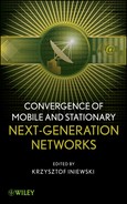
Because of the unique characteristics of MANETs—that is, the absence of an infrastructure, the unreliable network links, the scarce network resources, and the mobile, transient, and heterogeneous network nodes—research issues and challenges can be found in each of the network layers. Liu and Chlamtac [4] summarize these challenges and highlight research issues for each layer as shown in Figure 12.1.
Figure 12.1. Research issues in MANETs.
12.1.3 Integrated MANETs/3G Networks
An integrated MANETs/3G network is also recognized as a type of Multihop Cellular Network (MCN) in the wireless network domain. MCN is a concept contrasting with the traditional Single-hop Cellular Network (SCN) such as 2G, 2.5G, and 3G wireless networks. Lin and Hsu [17] first posed the concept. After that, many other researchers have contributed to the lower-layer connection techniques [18–23], routing strategies [24–26] and mobility management [27].
Cavalcanti et al. [28] summarizes the connection alternatives of a MANET and a 3G cellular network. In these alternatives, a general assumption is that users have two wireless interfaces: one to MANET and the other one to 3G. The users may communicate directly through 3G interfaces. They may also communicate directly through MANET interfaces. Furthermore, a user in a MANET may connect to a gateway or a relay, which can establish a connection with another user in 3G network. Another assumption is that MANETs and 3G networks are tightly connected; that is, all the users share the same 3G core network.
To illustrate how the integration is concretely done at the lower layers, we use two examples, iCAR [18] and UCAN [19]. They take different advantages of the integrated 3G/MANETs and they use different methods for integration. According to Fu et al. [56].
In iCAR, MANETs are used to balance the traffic load between the wireless cells. An entity, ad hoc relaying station (ARS), is defined to divert the traffic from congested cells to lightly loaded ones. ARSs are wireless devices deployed by the network operator. They have two air interfaces, one to communicate with the cellular base transceiver stations (BTSs) and the other to communicate with mobile host (MH) and other ARSs. Three strategies are defined for traffic relaying. First, an ARS directly relays new calls from a congested cell to a neighboring cell. This is called primary relaying. However, if an MH is not close to an ARS, the system will re-sort the traffics and follow the second strategy—that is, release the channel from the MHs that are close to the ARSs, relay their traffic to neighboring cells, and allocate the channel to the MH in need. In this case, an MH-to-MH call via ARSs only (i.e., without BTSs involved) is defined. The third relaying strategy, called cascaded relaying, is the double uses of the second strategy. It covers the situation when both cells, where the calling party and the called party are located, are congested.
In UCAN, MANETs are used to extend the coverage of the wireless cells. The system aims at improving the throughput using multihop routing when the quality of the signal in the downlink channel between the BTS and the MH is poor. Dissimilar to iCAR, it does not define the deployed entity. Instead, it uses proxy clients and relay clients to relay packets toward the destination MH. Proxy clients are the MHs that have better downlink signals with the BTS and act as the interface between the MANET and the cellular network. Relay clients are hops to relay the traffic between proxies and destination MHs. In order to find a proxy client, two discovery protocols have been proposed, a proactive greedy scheme and a reactive on-demand protocol. These protocols use the pilot burst information (that reflects the downlink channel condition) collected by the MHs to discover a proper proxy MH.
12.1.4 Multimedia Conferencing
Multimedia conferencing (also known as multimedia multiparty sessions) can be defined as the conversational exchange of multimedia content between several parties. It consists of three components: conference control, signaling, and media-handling. Conference control is related to conference policies, admission control, floor controls, and voting. Signaling is used to set up, modify, and tear down sessions. It is required before, during, and after the media transmission. Media handling is concerned with the transmission and the mixing of the media streams. It also performs the possible trans-coding between different types of media streams.
12.1.4.1 Classifications.
There are many classification criteria for conferencing. The most commonly used are presented in this section. According to Fu et al. [56].
Conferences can be with or without floor control. Floor control is a technology that deals with conflicts in shared work spaces [29]. It coordinates the concurrent usage of shared resources and data among participants of a conference. A typical example of floor control is the management of the turn of speaking in a conference—that is, how and when to allocate the audio channels to involved parties in order to ensure fairness and avoid collisions. Conferences can be prearranged or ad hoc. A prearranged conference starts at a predetermined time and is sponsored by specific parties. The duration of a conference may also be predefined. An ad hoc conference starts when the first two parties decide to create a session. Parties may join and leave during the conference, and it ends when the last two parties leave. Another criterion is whether the conference is private (closed) or public (open). A closed or private conference does not welcome parties to join freely. Only the parties who are invited by the conference participants can join. An open or public conference on the other hand publishes its information to all parties in a network. Any party can join the conference if and when it wishes. Yet another criterion is whether the conference has subconferencing capabilities. The subconferencing capability simulates a conference with different rooms as in the real world. In each room, called a subconference, parties can hear/see each other, but they cannot hear/see others that are in different subconferences.
The remaining commonly used criterion is the topology used for signaling and media handling. Schulzrinne and Rosenberg [30] has discussed four main topologies for signaling and media handling: end-system mixing, full mesh, multicast, and centralized. In end-system mixing, one of the participants in the conference does the mixing for all the other participants. In general, due to the limited capability of participants, very few participants can be supported in this type of conferences. In full mesh, every end-system does its own mixing and has a signaling link with every other end-system. Multicast is an enhanced form of full mesh. Every end-system still does its own mixing. However, packets are sent to a multicast address instead of being sent point-to-point. In centralized conferences, a conference bridge is defined to do mixing for all the end systems. Each end-system has a direct signaling connection with the bridge. In this model, a participant may either call the bridge to join a conference (dial-in) or be called by the bridge to join (dial-out). A similar but more recent classification has been presented in IETF RFC 4353 [31]. Three models are defined and different names are used: loosely coupled conference (use of multicast), tightly coupled conference (centralized model), and fully distributed conference (full mesh model).
12.1.4.2 Techniques and Standards.
IETF and ITU-T have developed standards for each aspect of conferencing. We present them in this subsection. We also present the related work on signaling for conferencing outside of the standard bodies.
12.1.4.2.1 Standards for Conference Control.
Conference control has been defined by ITU-T in T.120 Series [32]. The control policies are mainly focused on centralized conferences. From a historical point of view, early conference control contributions in IETF are based on loosely coupled, multicast conferences. Protocols such as Multimedia Conference Control (MMCC) [33], Agreement Protocol [34], and Conference Control Channel Protocol (CCCP) [35] were defined. Simple Conference Control Protocol (SCCP) [36] was the first draft that tried to map loosely coupled conference into ITU-T T.120 series. However, it still relies on multicast. Recently, IETF has changed its focus from loosely coupled to tightly coupled conference, known as a Common Conference Information Data Model for Centralized Conferencing (XCON [37]). It also defines Conference Policy Control Protocol (CPCP) [38] for centralized conference control. The IETF Binary Floor Control Protocol (BFCP [39]) is defined for floor control.
12.1.4.2.2 Standards for Media Handling and Media Control.
The most widely used media transmission protocols are Real-time Transport Protocol (RTP) and RTP Control Protocol (RTCP), which are defined by IETF RFC 3550 [40] and RFC 3551 [41], respectively. They are also included in H.323 series as real-time media transport protocols. RTP provides end-to-end network transport functions that are suitable for applications that transmit real-time data, such as audio, video, or data, over multicast or unicast network services. It supports the use of translators and mixers. RTCP allows monitoring of the data delivery of RTP.
The Media Gateway Control Protocol (or Megaco) is a signaling protocol between conference signaling and media handling. It is defined by IETF RFC 3525 [42] and ITU-T H.248.1 [43]. The idea is a separation of call control and media handling logics, adding the control commands between them. This separation introduces more flexibility for deploying multimedia conference services. The 3GPP has also used this protocol for conferencing. The Media Server Control Markup Language (MSCML [44]) is a new emerging IETF standard for media control. It embeds media control command as an XML format in SIP message body. Comparing to Megaco, it is much more lightweight but is with less functionality.
12.1.4.2.3 Standards for Signaling.
Signaling protocols have also been defined by both ITU-T and IETF. The most widely applied signaling protocols are H.323 [45] from ITU-T and Session Initiation Protocol (SIP) [46] from IETF.
H.323 is a set of specifications. It is actually the very first set of signaling standards created after Signaling System 7 (SS7 that is used for circuit switching networks). Reference 47 provides an overview. H.323 defines four entities: terminal, gateway, gatekeeper, and Multipoint Control Unit (MCU). Basic signaling and media handling functions of H.323 are located in terminals. A gateway is a component that bridges H.323 sessions to other types of networks. A gatekeeper, although it is not a mandatory entity, may have many functions such as user admission, zone management, bandwidth control, and address translation. The specifications of H.323 cover more than signaling. The H.323 protocols are binary encoded and include three different signaling protocols: Registration Admission and Status (RAS), H.225, and H.245. RAS is used between end-points and gatekeepers. It enables gatekeeper discovery and registration/un-registration of end-points with gatekeepers. H.225 is the protocol for call establishment and teardown. H.245 enables media capability negotiation.
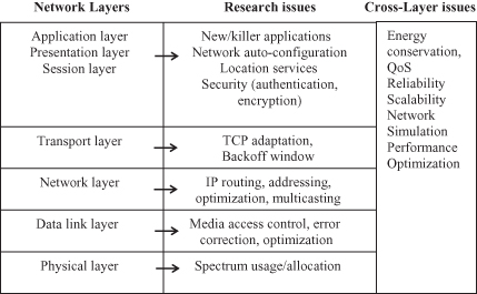
Multimedia conference control in H.323 is done via MCU. An MCU can be further divided up into two entities: multipoint controller (MC) and multipoint processor (MP). MC handles signaling while MP handles media. MP is an optional entity. It is not required in a decentralized conference model in which media are distributed through multicast. MC is mandatory. It is a central control point for both centralized (i.e., where media mixing is done in a central MP) and decentralized models. The conference models defined in H.323 are shown in Figure 12.2. H.323 has been applied in 2G wireless system for voice over IP (VoIP) services.
Figure 12.2. Conference models for H.323.
SIP is specifications including a baseline protocol and a set of extensions. In baseline protocol, it defines four entities: user agent (UA), proxy server, location server, and registrar. Session control functions are located in UAs. SIP servers are nonmandatory entities that help to route SIP messages and to locate SIP user agents. Reference 48 gives an overview of SIP. SIP is lightweight and extendable, and it has been adopted by the two main standards bodies for 3G networks (i.e., 3GPP and 3GPP2) as the sole signaling system for multiparty sessions. It is a text-based request/reply protocol.
IETF has been working on SIP as conferencing signaling protocol since year 2000. SIP has been used for two conference models—loosely coupled and tightly coupled. A loosely coupled conference is based on multicast. IETF draft [36] describes SCCP, a loosely coupled conference control protocol that uses SIP as the signaling protocol. The signaling architecture is centralized. Signaling messages are exchanged between a controller and a participant through multicast.
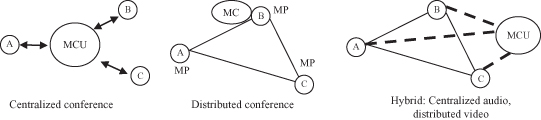
A tightly coupled conference is central-server-based. SIP usage in this sort of conference model is defined in reference 31. SIP creates sessions between each participant and a conference focus (i.e., the central server). This conference model is with more interest because it is also applied by 3GPP [49]. Figure 12.3 shows the simplified 3GPP 3G conferencing architecture. According to Fu et al. [56].
In the architecture, the conference focus can be implemented in the media resource function controller (MRFC) and/or in the conferencing application server (AS). The MRFC is the functional entity that handles signaling. It considers the media resource function processor (MRFP) as a default media mixer. The AS hosts conference applications. Any party that wants to participate in a conference should either invite the conference focus (i.e., following the dial-in model) or be invited by the conference focus (i.e., following the dial-out model). In addition to the MRFC and the AS, there is another functional entity, user equipment (UE).
A UE is a conference participant that has the required conferencing functionality in the end-users’ terminals.
12.1.4.2.4 Signaling Approaches from Outside of the Standard Bodies.
Several approaches have been proposed from outside of the standards bodies. Some of them target specific issues that are not solved by the standard approaches, while others propose more comprehensive solutions. The works proposed in Koskelainen et al. [50] are examples of the former, while GlobalMMCS [51] and ICEBERG [52] are examples of the latter. According to Fu et al. [55].
The SIP-based conference defined in Koskelainen et al. [50] is another example of work for using SIP for conferencing. It extends the tightly coupled conference model of SIP in order to improve the scalability. Multiple conference focuses are proposed, and each focus manages a set of local participants. The conference focuses are interconnected and form a tree structure.
GlobalMMCS [51] is designed to bridge H.323, SIP, access grid clients, and 2.5G/3G cellular phones in audio–visual collaborative applications. The system makes use of a publication/subscription-based message delivery middleware, the NaradaBroking overlay network. As far as multimedia conferencing is concerned, the system borrows the ideas of MCU, MC, and MP from H.323. However, unlike H.323, the MCs can be distributed. There can be several in the same conference, each one managing a subset of participants.
ICEBERG signaling [52] proposes a signaling system for the management of dynamic and multidevice multiparty sessions. Unlike the other signaling protocols such as SIP, it is a signaling system that is directly designed for multimedia conferencing. Two entities are defined: call agent and call session. They are both dynamic entities created during call session establishment. The call session entity is the control center that manages all the information related to that session. There is one call agent per party. It manages the information related to that party. Changes related to the session are propagated as follows. A designated serving call agent periodically receives a report from each party in the session, and it forwards the report to the call session entity. The call session entity maintains the states of all of the parties in a table, and it updates the table when it receives the reports. It also propagates the information to each of the call agents.
12.2 SIGNALING FOR CONFERENCING IN 4G
In this section we introduce signaling architectures and protocols for conferencing in 4G. We present the signaling architectures for MANETs and integrated MANETs/3G networks.
12.2.1 Signaling for Conferencing in MANETs
The signaling for multimedia conferencing in MANETs is very challenging. A signaling scheme not only needs to establish, modify, and terminate sessions, but also has to take into consideration the network statuses such as the lack of infrastructure, the frequently changing participants, and the limited resources. A very basic requirement for conferencing signaling in MANETs is that none of the signaling entities can be a permanent or static central-control point. The other functional requirement is that the system should be able to dynamically propagate conference-related information (e.g., who joins, who leaves) to all the involved parties. This is not an easy task, because conferences are normally very dynamic in MANETs. Parties can join and leave at any time and very frequently. A party may leave the conference when it decides to do so or when it is forced to because it has moved out of the coverage area or its battery power is used up. We term the first case (which is general to all networks) “voluntary departure” and call the second (which is specific to MANETs) “unintentional departure.” If a party in a conference temporally moves out of range or if its link breaks for a very short time, the sessions that it has maintained should be recovered after its connections are recovered.
Signaling for conferencing in MANETs has not yet been standardized. IETF discussed some issues related to distributed SIP in Kelley [53], which is applied later in the proposal: SIP framework for MANET [54]. These early investigations do not comprehensively cover the signaling requirements for MANETs. The cluster-based signaling protocol [55] is so far a much-detailed proposal for conference signaling in MANETs. It discusses different signaling issues and provides simulation results. We will first discuss early investigations and then provide more detailed information on our cluster-based signaling solution.
12.2.1.1 IETF Distributed SIP and SIP Framework for MANETs.
SIP has been addressed for a fully distributed model. In the model, each participant maintains a SIP session with other participants. Reference 53 describes this approach in detail. This is of special interest to MANETs because it only involves SIP end systems (UAs) and no central server is required. However, this approach has several limitations. A first drawback is the way the session-related information is dynamically propagated to parties. There is a problem when two (or more) parties are invited to join an ongoing session at the same time. There is no general solution to ensure that each of the invited parties is made aware of the other invited parties. This problem is identified as the “coincident joins problem,” and no solution is provided.
The framework defined in Khlifi et al. [54] applies the architecture defined in Kelley [53] for MANETs, but it resolved the “coincident joins problem.” It proposes a conference leader that propagates session-related information to all participants. Any participant change should report to the conference leader. This work cannot support a large number of participants due to the full-meshed signaling connections among participants. In addition, it does not consider the issues such as session recovery.
12.2.1.2 Cluster-Based Signaling in MANETs.
Clusters enable scalability without centralization, and they can help in solving the signaling issue in MANETs.1 A cluster-based signaling architecture for conferencing in standalone MANETs is proposed in Fu et al. [55]. The clusters are formed in the application layer and only when there is a conference. We first present the architectural principles, followed by a description of the clusters’ operational procedures. We then discuss two critical issues related to the operational procedures: how to exchange node capabilities and how to handle unintentional departure and session recovery.
12.2.1.2.1 The Architecture and General Principles.
Figure 12.4 gives an overall view of the cluster-based signaling architecture. The only functional entity is the signaling agent (SA). There is one per party, or more generally, one per node in a MANET. They are grouped in clusters that we call signaling clusters. These clusters are application-level clusters and are independent of lower layer clusters such as routing clusters. In each cluster, at any given time, there is one and only one cluster head (i.e., super-member), and all the other members of the cluster are connected to it. A super-member has direct signaling links to the super-members of the neighboring clusters.
Figure 12.4. Signaling architecture for standalone MANETs.
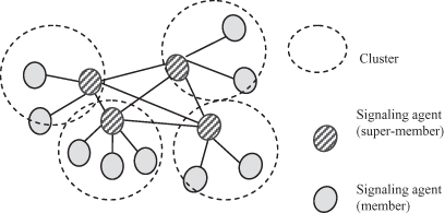
There are two general parameters of a cluster: split value (Sv) and merge value (Mv). Every node in a conference maintains the same Sv and Mv. If the size of a cluster reaches Sv, the cluster will split into two clusters. If it reaches Mv, the cluster will find another cluster to merge with.
A super-member is responsible for keeping track of the information of its members and its neighboring super-members. It also propagates the information when there is a change in membership. In addition, it detects the eventual unintentional departures of the nodes connected to it by sending periodic heartbeat messages.
In this architecture, it is the node with the most capabilities that is elected as the super-member. A participant that initiates a conference is responsible for collecting the capabilities of the called party before the conference is initiated. Super-members keep track of the capability changes of their members and neighboring super-members during the conference.
12.2.1.2.2 Operational Procedure of Clusters.
Clusters are dynamically created and deleted for conferencing. The signaling system is responsible for maintaining the state of conference and clusters. Each signaling cluster has a life cycle. The first phase is its creation. A super-member is elected in this phase. After its creation, the cluster moves to an active phase. The membership of the cluster evolves (parties join and leave). These changes may lead a cluster to split into two, or to merge with another cluster. Ongoing activity may also lead to the election of a new super-member, triggered by the departure of the super-member, for example. The life cycle ends with the deletion of the cluster. In this section, we describe the signaling procedures related to each of the phases of the cluster life cycle.
(a) Cluster Creation and Deletion.
The first cluster is created when a conference starts. The creation procedure is as follows: First, the party (called the initiator) that wishes to establish a session collects the capability of the called party. It compares its own capability to the capability of the called party and designates the one with more capability as the super-member. Second, it requests the super-member (itself or the called party) to create a session. The initiator needs to set the Sv and Mv and passes the parameters to the called party. After the first session is set up, the super-member starts to periodically collect the capabilities of its members.
The last cluster is deleted when the last two parties leave the session. All the states and parameters of the cluster are cleared.
(b) Super-member Election.
An election algorithm is used whenever there is a need to select a new super-member among several candidates. This happens when a new cluster is created or when a cluster merges with another cluster or when a super-member leaves. The basic rule is that the candidate with the most capability is selected as a super-member. The election algorithm is quite straightforward. The capability of each super-member candidate is compared to other capabilities, and the one with most capability wins.
(c) Member Joining and Leaving.
Both members and super-members can invite parties to join a conference. If it is a super-member that is inviting and it is capable of handling more members, the super-member directly establishes a session with the party. If the super-member cannot handle more members, it may ask a neighboring super-member to do so. If a member invites a party, that member will ask its super-member to establish the session. A new member is then added to the cluster. The super-member of the cluster propagates the membership change to neighboring clusters.
Any participants, including members and super-members, may leave a conference whenever they want to. In the case of a member departure, the member terminates its connection with its super-member and the super-member propagates the membership change to the neighboring clusters. With the departure of a super-member, that super-member designates a new super-member (choosing the member with most capability among the member list) before leaving. It passes its member-list and neighboring super-member list to the new super-member. The new super-member sets up a session with each member and each neighboring super-member and forms a new cluster. After this procedure, the old super-member terminates all its connected sessions. In the case where there is no member in a cluster, the super-member that wishes to leave simply terminates all its connected sessions.
(d) Splitting.
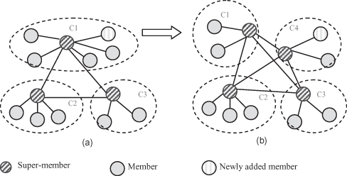
When a new member is added to a cluster, the super-member initiates a split procedure if the size of the cluster reaches Sv or if the super-member does not have enough capability to handle more members. A cluster may also split when its super-member does not have enough capability to handle its existing members. This happens, for instance, when the battery power of the super-member decreases. First, the super-member selects a new super-member, based on capabilities. It also selects half of its members that are to become members of the new cluster. The selection may be by random or according to some rules, such as the sequence number of members. The super-member that wishes to split the cluster then asks the new super-member to form a new cluster that contains the selected members, and it passes the selected member list and neighboring super-member list to the new super-member. The new super-member creates a new cluster by establishing sessions. The super-member then terminates sessions with the selected members. Figure 12.5 shows signaling architectures before and after splitting.
Figure 12.5. Cluster splitting (a) Before splitting. (b) After splitting
(Copyright IEEE 2009 [55].)
(e) Merging.
If the size of the cluster diminishes to Mv, the super-member initiates a merger procedure. This procedure starts by a searching for an existing cluster with which to merge, with the constraint that the size after the merger will be less than Sv. A new super-member is elected as soon as the merger begins. The new super-member will be one of the two super-members (the one with more capability) of the two clusters. The procedure continues as follows: The elected super-member establishes sessions with the members of the cluster to merge with. The un-elected super-member then terminates sessions with its members and sets the elected super-member as its super-member, and it becomes a regular member. The merger information will then be propagated to the neighboring super-members.
(f) Information Propagation.
In order to maintain a signaling cluster system, efficient information propagation is required—that is, rapid propagation with as little introduced overhead as possible. In this architecture, super-members are responsible for propagating membership and capability information whenever there is a change. The information can be propagated to all the signaling agents in no more than two hops.
(g) The Issue of Coincident Behavior of Participants.
One issue of a distributed signaling architecture is the state synchronization when there are coincident behaviors of participants in the conference. Such behaviors may cause inconsistent states among participants; for example, with a coincident joining (defined in Kelley [53]), two newly joined parties have no way to know each other and no session will be established between them, and thus the fully distributed signaling architecture cannot be maintained. However, with the information propagation procedure, the cluster scheme defined in this proposal can handle most coincident behaviors. In some cases, protection mechanisms are used to prevent inconsistencies. We present this issue case by case:
Coincident Join. Two or more parties join a conference at the same time. They may join the same cluster or different clusters. The cluster scheme can handle this case because the coincidently joined parties do not have a direct session with each other. Instead, they establish sessions with the super-members that are already in the cluster, and later they can “know” each other from their super-member(s).
Coincident Departure. Two or more participants leave a conference at the same time. They may leave the same cluster or different clusters. Similar to the first case, the cluster scheme can handle the coincident departure of members and less than two super-members. The scheme does not support coincident departure of super-members, so it defines a protection phase when a super-member leaves. A super-member should reject any session establishment or termination request when it starts to leave. The protection phase ends when the super-member has completed the leaving procedure. Within this protection phase, a super-member leaving procedure will fail if another super-member is leaving at the same time, because the newly selected super-member cannot establish a session with a leaving neighboring super-member. If a super-member fails to leave, it will retry after a random period of time.
Coincident Splitting. Two or more clusters split at the same time. With the mesh structure of super-members, the super-members in older clusters maintain a session with every newly split super-member. After a run of the information propagation procedure, a newly split super-member will have knowledge of the other new super-members. The logic added in order to handle this case is that if a super-member finds that it has not established a session with a neighboring super-member and if it has a higher address, it will establish a session with that super-member.
Coincident Merging. Two or more pairs of clusters merge at the same time. The scheme can handle this case because there is no new super-member elected. The cluster state can be propagated to all neighboring super-members.
There are two other critical issues related to the signaling procedures. The first is the participant capability discovery that is critical to super-member election, and the second is the detection of unintentional departure and session recovery. We present how the cluster scheme handles the two issues.
12.2.1.2.3 Capability Exchange Mechanism.
A simple application-level protocol is presented as part of the cluster-based signaling scheme for handling capability discovery. The entity involved is the signaling agent. There are three types of messages defined: Cap_subscribe, Cap_notify, and Cap_publish. Cap_subscribe is a request message containing a subscription interval. Cap_notify is a response message containing a sequence number and the current capability level, and Cap_publish is a message containing the current capability level.
Cap_subscribe is used in the following scenarios:
- When the initiator of a conference establishes the first session, it sends the message to the called party and sets the subscription interval to zero. In this case, the called party sends only one Cap_notify back to the initiator with its current capability loaded in the message.
- A super-member sends a Cap_subscribe message to a member when a session is established. In this case the subscription interval is set to a nonzero value, and in each interval period the member sends back a Cap_notify message loaded with its current capability.
- A super-member sends a Cap_subscribe to a member with a zero subscription interval value. The member sends back a Cap_notify response and stops the periodic Cap_notify messages.
Cap_publish is sent between super-members. When its capability is changed, a super-member sends a Cap_publish to every neighboring super-member.
12.2.1.2.4 Unintentional Departure Detection and Session Recovery.
A failure-detection and recovery mechanism is used by the signaling architecture for handling the unintentional departures. The basic idea is that each session in a conference maintains a heartbeat—a periodical exchange of a request and a reply. There are three timers defined: heartbeat rate Th, transaction timer Tt, and recovery timer Tr. A heartbeat sender sends a request to a heartbeat receiver in each period of Th. A backup super-member list is contained in the request. If the sender does not receive a response in Tt, it will resend the request. If it does not receive a response after n resent requests, it will determine that the session is inactive. If a receiver does not receive a heartbeat request in Th + Tt*n, it will determine that the session is inactive. An inactive session will be removed from the conference, and a recovery procedure will be activated.
The idea of session recovery is that if a sender or a receiver detects that the last session has terminated, it does not remove the conference state immediately, but keeps the state for a time (Tr) and tries to establish a session with one of the backup super-members in each period of Tt until one session is created.
12.2.2 Signaling for Conferencing in Integrated MANETs/3G
An important scenario in 4G is the integrated MANETs/3G networks. We present the conferencing signaling for the scenario in this section. It is an integration of 3GPP 3G conferencing architecture and the clustering architecture presented in Fu et al. [55]. In the rest of this section, we will present the proposal in detail.
12.2.2.1 Network Assumptions.
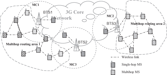
The integrated MANETs/3G network considered in the proposal [56] is shown in Figure 12.6. According Fu et al. [58].
In the figure a multihop routing area is defined as an area in which all the nodes are working on a MANET interface, and the nodes can reach each other by direct wireless connections or multihop routing. It also shows that there is more than one multihop routing area in the system. The assumed network supports three types of devices: devices with only MANET interfaces, devices with both MANET and 3G interfaces, and devices with only 3G interfaces. The first two types are called the multihop mobile station (MS), and the third is called the single-hop MS.
12.2.2.2 Architectural Principles2
12.2.2.2.1 The Architecture.
The architecture is depicted in Figure 12.7. It includes three entities: the signaling agent (SA), the conference focus (MRFC/AS), and the conference gateway (CGW). The MRFC/AS is the entity defined in the 3GPP standard [49]. In this architecture, its functionality as per the 3GPP standard is enhanced. The enhancement is a CGW discovery functionality—that is, the ability to find a suitable CGW that can handle sessions with the participants in MANETs. The SAs are conference participants. They are either 3GSAs (i.e., participants in 3G), or MSAs (i.e. participants in MANETs). 3GSAs are the signaling parts of the 3G User Equipment defined in reference 49. They can establish sessions with the MRFC/AS. MSAs are the same as the SAs defined in Section 12.2.1.2. An MSA can be either a super-member or a simple member. Here also the CGW discovery functionality is needed in addition to the functionality of the MSA defined in Fu et al. [55]. It should be noted that 3GSAs and MSAs may run different signaling protocols.
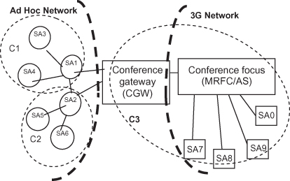
The CGW is a new entity introduced. It is a mediator deployed by the 3G network operator (or a trusted third party). It has an infrastructure-based interface that is connected to the 3G conference focus. It also has a MANET interface that is connected to MANET SAs. Unlike the client proxy defined in UCAN or the ARS defined in iCAR, the CGW is an application layer entity. Its two interfaces are not physical air interfaces, but instead they are application layer interfaces to signaling components. A CGW has six major functions. First, it has the functionality of a signaling agent that is capable of establishing sessions with MSAs and with the conference focus. Second, it understands the signaling protocols for multimedia conferencing in both MANET and 3G, and it performs the translation (if required). Third, it understands the conferencing signaling architectures (e.g., centralized versus distributed) used in both MANET and 3G, and it does the mapping (if required). Fourth, it collects the membership information in both networks, converts it (if required), and distributes it. Fifth, it provides the functionality of publication and discovery so that MSAs and the conference focus can find and use its services. Sixth, it provides registration functions and manages the repository of MANET participants.
The architecture relies on three main principles. First, participants in MANET see the CGW as a special super-member that never leaves, splits, or merges with other super-members. Second, participants in 3G (i.e., 3GSAs) see the MRFC/AS as a centralized control point to which every participant, in 3G networks or in MANETs, is connected. Third, the MRFC/AS sees the CGW as a sub-focus that aggregates and manages sessions for MANET participants. The basic assumption is that participants that are not 3G users are implicitly seen by the 3G conference focus as MANET participants, to which sessions are created through a CGW. The same assumption is made for MSAs.
12.2.2.2.2 CGW Discovery.
The CGW can be discovered by the 3G conference focus and by the MANET participants. The architecture proposed to reuse any of the MANETs service discovery protocols such as Konark [57]. Two basic scenarios are presented. First, a CGW periodically publishes its location and capability to MANET nodes. The MANET node caches the CGW information when it first receives it, and it registers with the CGW. Second, a MANET node sends a CGW request message that contains CGW capability requirements to the network. A MANET node that has the proper CGW capability information or a CGW that matches the capability requirements can respond. The MANET node that receives the responses then registers with the CGW.
CGW location information contains the CGW’s address and listening port. CGW capability information includes parameters such as the “signaling protocols supported,” “conference type supported,” “network information,” “architectures supported,” and “encoding supported.”
12.2.2.3 Conferencing Scenarios.
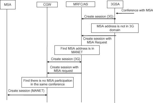
Four different conferencing scenarios are enabled using the signaling architecture: conferencing with 3GSA parties, conferencing with both 3GSA and MSA parties, conferencing with MSA parties in the same multihop routing area, and conferencing with MSA parties in different routing areas. The first and the third scenario do not require the use of a CGW. The second scenario requires CGWs to perform protocol translations and signaling routing. The last scenario does not require a protocol translation, but it uses CGWs and the 3G conference focus as signaling routing mediators. Here, we show one example scenario of conference initiation.
Figure 12.8 depicts sequence that a 3GSA initiates a conference with an MSA. The 3GSA first creates a session with its MRFC/AS using the 3G signaling protocol. Then it requests the conference focus to create a session with the MSA. The conference focus finds that the MSA is in a MANET. It then creates a session with the CGW and asks the CGW to create a session with the MSA. Finally, the CGW creates a session with the MSA using the signaling protocol of MANET and designates the MSA as a super-member.
Figure 12.8. Conference initiations: A 3G participant initiates a session with a MANET party.
(Copyright IEEE 2006 [56].)
12.3 OPTIMIZATION OF SIGNALING SYSTEMS: USING CROSS-LAYER DESIGN
In this section we study the performance and related issues of the conferencing signaling proposals for MANETs and integrated MANETs/3G networks. We present a solution [58] to optimize the signaling performance using a cross-layer design.
12.3.1 Performance Issues of Signaling Architectures3
Four issues have been identified for the signaling proposals: the overhead introduced by the heartbeat message, the overhead introduced by capability exchange protocol, the CGW deployment issues, and the suboptimal routing issues.
Application-Layer Heartbeat.
The heartbeat mechanism proposed for the signaling architecture in MANETs deals with the unintentional departures of nodes. Although a reduction of the overhead introduced by the heartbeat messages have been considered (e.g., a one-way request/replay scheme used and the heartbeat messages are simple and lightweight), it can be found that the heartbeat does introduce significant overhead. Especially when the heartbeat rate is high, the overhead can exceed the session establishment overhead [55]. On the other hand, this overhead cannot be removed because the detection and handling of unintentional departures is important for conferencing in MANETs.
Application-Layer Capability Exchange.
The application-layer capability exchange scheme is used for optimal use of node capabilities. The capability information is maintained by each super-member by periodically exchanging node capabilities between a super-member and its members. Similar to the heartbeat message, even though the protocol is lightweight, the overhead introduced is nontrivial because of periodical messages.
Both heartbeat and capability exchange mechanisms help to meet the signaling requirements that are not related to session management, but are necessary for handling the particularities of MANETs. For example, the unintentional departure is often caused by link break, node moving out of range, or node crash. These issues are common to every layer of MANETs, and they have been discussed frequently in relation to lower layers. A proof is that the AODV [13] routing protocol has used three nonresponded “Hello” messages to detect a link break. The same thing happens to the optimal use of node capabilities. The optimal use of capabilities is a common target for all MANET layers because resources in MANETs are scarce. Actually, some of the lower layer protocols have considered this requirement in their design. For example, WCA [59] uses the capability of nodes as one of the criteria to decide cluster heads. Thus, we doubt that the use of heartbeat and capability exchange mechanisms in the application layer is not very efficient, but cross-layer design helps to share information among layers and to improve the overall performance.
CGW Deployment and CGW Publication/Discovery.
CGW is a key entity in the integrated signaling architecture. The proper deployment of a CGW can improve performance. There are two questions to be answered. The first is where to deploy a conference gateway. The second is how many conference gateways should be deployed. These questions are not answered in Fu et al. [56]. Furthermore, the CGW publication/discovery is yet a task that requires periodical exchange of messages at the application layer. Are there opportunities to reduce this overhead?
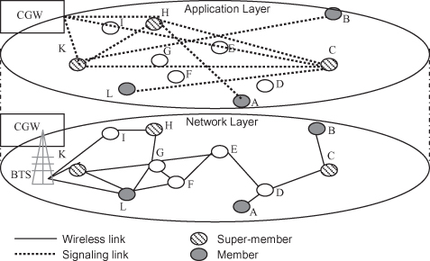
Suboptimal Routing.
This is an issue caused by application-layer clusters. A new cluster member joins a cluster when the super-member or a member of the cluster invites it. The scheme has not considered whether the joiner is physically close to the cluster. This may introduce serious performance problems. In Figure 12.9, for instance, the shortest path between party A and party B for the routing layer is 3 hops. If signaling clusters in the application layer have been formed, the real path distance between party A and party B will be 11 hops: 4 hops between A and its super-member H, 5 hops between B and its super-member K and 2 more hops between the two super-members H and K. This issue can be somehow avoided if the application layer “knows” physical location of nodes; for example, if super-member K knows that party B is close to super-member C, it may not invite B but asks super-member C to do so. We believe that cross-layer design can help in this situation.
From the above analysis, a need for cross-layer design is identified. Two of the performance issues are directly related to lower-layer problems such as routing and link-break detection. The issue of optimal resource usage is common to every layer and the CGW deployment is related to lower-layer network architectures. In the next section, we will introduce the concept of cross-layer design and the requirement of cross-layer design for signaling optimization. We also analyze some existing cross-layer design proposals with respect to the requirements.
12.3.2 Cross-Layer Design for MANETs
Cross-layer design refers to protocol design done by actively exploiting the dependence between protocol layers to obtain performance gain. This is unlike layered design, where the protocols at different layers are designed independently [60]. Layered design has obtained great successes in today’s infrastructure-based networks such as telephony networks and Internet, while cross-layer design is mainly motivated in wireless networks. Wireless networks have their distinctive characteristics such as user mobility, frequent link failure, limited link capability, and limited battery power of mobile devices. The argument is that applying layered design in wireless networks usually causes suboptimal performances, but a careful cross-layer design helps to solve the issue. A cross-layer design may remove the duplicate functionality or data in layers. It may also optimize the parameters in each layer so that the performance in a single layer or in a whole system is enhanced.
The cross-layer designs can be classified into four types [60]: interface breaking, merging of adjacent layers, design couplings, and vertical calibrations. The interface breaking can further be sorted into three types: upward information flow, downward information flow, and back-and-forth. The design coupling and merging of adjacent layers are self-explainable from their name. The purpose of vertical calibration is to perform adjustment in each layer in order to achieve a global performance gain. A method of implementing vertical calibration is using a shared database for all layers.
12.3.2.1 Cross-Layer Design Requirements for Signaling Optimization.
The cross-layer design for signaling optimization should meet the following requirements. First, it should be easy to implement and does not introduce too much network overhead. Second, it should respect some cautionary aspects of cross-layer design—for example, no design loop and an ease of upgrade. Third, the cross-layer information should be time-sensitive. This is important for the signaling system because conferencing is a real-time application. Fourth, the interoperability should be considered for the integrated signaling system. For example, an SA with a cross-layer design should be capable of interacting with an SA designed in traditional manner.
12.3.2.2 Related Work in MANETs.
We divide the existing cross-layer design proposals in MANETs into two categories: global versus local solutions. The former usually presents new cross-layer design methods that are applicable for different architectures and benefit different layers. The latter consists of local solutions for specific architectures and requirements. For example, the work defined in Setton et al. [61] uses cross-layer design for the optimization of real-time video transmission. Local solutions are difficult to adapt for other applications or situations. Therefore, we will not discuss them further. Four global cross-layer design solutions are examined. CLASS [62] follows the method of direct communication between layers. It proposes a general mobility management architecture that allows for direct signaling flows between non-neighboring layers. This signaling interaction enables efficient mobility management for the whole system. However, it does not meet the requirements. For example, it requires logical changes in each layer, which is complicated to implement and upgrade. In addition, it can lead to conflicts and loops if the signaling has not been designed very carefully.
MobileMAN [63] considers the cautionary aspects of cross-layer design, and it makes use of a shared database. It defines a repository called Network Status from which each layer can write and read information. It provides optimization for all the network functions and improves local and global adaptations. However, it is not easy to implement because it requires the redesign of protocols in each layer. Furthermore, the expiration of the data in the repository have not been discussed, so the optimization scheme may not be efficient for time-sensitive applications. References 64 and 65 present some other drawbacks of MobileMAN; for example, it may be cumbersome for protocols that neither write nor read the Network Status.
CrossTalk [64] extends the vision of MobileMAN. It introduces a global view of the network status while specifying the Network Status defined in MobileMAN as a local view. It is capable of providing real-time information for the optimization processes. However, the global view is collected through a data dissemination procedure that incurs a significant overhead.
With the design goals of rapid prototyping, minimum intrusion, portability, and efficiency in mind, ECLAIR [65] is proposed for the optimization of mobile device protocol stacks. It uses an approach similar to that of MobileMAN and CrossTalk. The difference is that it not only collects data from layers and stores them in a repository, but also develops the optimization processes outside of the protocol stack. This abstraction makes the design more flexible and ensures a fast deployment. Similar to MobileMAN, it does not consider expiration of data, so the real-timeliness requirement is not fulfilled.
12.3.2.3 Related Work in Integrated MANETs.
In the context of integrated MANETs (or MCNs), cross-layer design has been considered recently (e.g., references 66 and 67). The work in reference 66 provides a cross-layer design for BTS routing discovery. It adjusts the functionality of physical, MAC, and network layers. It also collects information from the three layers so that an efficient route can be discovered. The performance evaluation shows that the proposed schemes can achieve faster route discovery and more reliable route setup. However, the proposal is a specific method that cannot be used by our signaling system. Furthermore, it has not considered interoperability issue. Similar to what is presented in reference 66, reference 67 presents another MCN routing protocol using cross-layer design. It considers a set of constraints (e.g., interference level) when discovering a route. These constraints are collected from physical or MAC layer. Like reference 66, this work cannot meet our requirements. To the best of our knowledge, there is no global cross-layer design solution proposed for integrated MANETs.
In next section we present the cross-layer architecture [58] that is designed for signaling optimization and is also generally suitable for application-layer optimizations.
12.3.3 A Cross-Layer Optimization Architecture
The cross-layer optimization architecture is shown in Figure 12.10. In this architecture, the shared database method is used and the cautionary aspects of cross-layer design are considered. The general principles are as follows: An application protocol defines optimization schemes and specifies the types of information that it wants to acquire from lower layers. The lower layers provide the information, which is stored in and retrieved from a shared database.
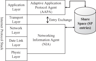
12.3.3.1 Entities.
The architecture involves three entities: Share sPace (SP), Adaptive Application Protocol Agent (AAPA), and Networking Information Agent (NIA). SP is a repository from which application protocols can retrieve lower-layer information. A share space contains a set of entries. Each entry represents one type of information. It contains an entry type, an entry value, and a keep-fresh timestamp, which is used to ensure the freshness of the information. If the information has not been updated for a given period of time, it will expire.
An entry is initially defined by an AAPA, which is responsible for translating the information types that are requested by application protocols into common entry types. These common entry types are exchanged and understood by AAPAs and NIAs. An AAPA is also responsible for creating entries in the SP. An NIA is responsible for collecting information from the lower layers and updates the relative entries in the SP. When there is a new update, the SP will inform the AAPA and the AAPA will then cache the updated information, reformat it, and send it to the application protocol.
The purpose of using AAPA and NIA is to mask the complexity of the cross-layer design so that existing protocols in single layers do not need to have major upgrades to support cross-layer optimization. The protocols in the lower layers only need to open their data structures to the NIA, and the application protocol simply sends requests to and gets responses from its AAPA. Any functional upgrade or version change in a layer is still independent of other layers. However, the AAPA and NIA should be upgraded accordingly.
12.3.3.2 Benefits of the Optimization Architecture.
This architecture benefits from the advantages of both layered design and cross-layer design. Compared to the existing proposals, the architecture is more application-layer oriented. Although shared database-based proposals such as MobileMAN and ECLAIR have defined some standard parameters for each layer, the shared data cannot really adapt to the different requirements of diverse applications. For example, routing cluster information is useful for optimizing a clustering-based application but it may not be considered as a standard parameter. This architecture makes it possible to exchange the data entries, and the new entries can be negotiated before performing an optimization. This allows space for customization of cross-layer parameters.
In the solution, the lower-layer information is retrieved locally. Timestamps are used to ensure the freshness of the information. There is no extra spreading overhead introduced in the network. On the other hand, the SP may not include as much of the information as that included in the global view defined in CrossTalk, but it includes necessary information required by application. Similar to ECLAIR, our architecture is flexible and quickly deployable. The application optimization schemes are designed independent of basic application logics. Thus, it can simply return to the basic logic if an optimization is not performed.
12.3.4 Optimization Schemes
There are six optimization schemes that can be applied in application layer: link-break handling, capability usage, suboptimal routing, super-member election based on clustering, super-member election based on signal power, and CGW deployment. The last two schemes are specific to the signaling for an integrated MANET/3G network. As a cross-layer design approach, each scheme uses a particular type of information from lower layers. There is no specific lower layer protocol required for the architecture. The general principle is that an optimization scheme is only performed when the lower-layer protocol(s) can provide the related information. This principle ensures that the optimized signaling scheme can run on different lower-layer routing protocols. It should be noted that the six optimization schemes are independent of each other.
12.3.4.1 Common Entries.
Six common entries are defined using the format <type, value, timestamp>. These entries are the routing table <routing_table, route_list, timestamp>, the node capability list <node_capability, capability_info_list, timestamp>, the neighbor list <neighbor_hop_list, address_list, timestamp>, the routing-layer clustering <routing_cluster, cluster_info, timestamp>, the routing topology <routing_topo, route_list, timestamp>, and the signal power <signal_power, power_value, timestamp>.
In the routing table entry, each route in the route_list consists of a source address, a destination address, a path, a hop count, an active status, and a timestamp. In the node capability list entry, each capability_info consists of a node address, capability types, and corresponding capability values. In the neighbor list entry, a list of neighboring nodes’ addresses is stored. In the routing layer clustering entry, cluster_info contains a cluster head. If the node is a cluster head, it also contains a list of cluster members. This entry may not contain all of the nodes’ capabilities. The routing topology entry stores the routes to reach every MANET node in an integrated architecture. In the signal power entry, a signal power value is stored. The signal power of a node is its wireless signal strength to the BTS.
12.3.4.2 General Optimization Schemes for Signaling in MANETs.
Link Break Handling Optimization Scheme.
This is performed when the routing table entry is updated. Every routing protocol provides this information. A super-member checks the route status for each of its connected members and super-members. If it discovers a route failure, it will terminate the session. This scheme helps the signaling system to handle an unintentional departure gracefully without using a heartbeat mechanism.
Capability Usage Optimization Scheme.
When the first super-member is elected, participants check their local node capability list. If there is a fresh capability list, the participant will copy and use this list for super-member election; that is, the participant with the highest level of capability becomes the super-member. After the establishment of the first session, the super-member checks its local capability list only when it needs to elect a new super-member. This scheme can only be invoked when the lower layer protocol takes node capabilities into consideration. Using this scheme, it can avoid invoking the application-layer capability exchange mechanism.
Suboptimal Routing Optimization Scheme.
This uses the entry of the neighbor list. Some of the routing protocols (e.g., proactive routing protocols) can provide this information. The scheme can be described as follows.
- When a new member joins the conference, all the super-members are informed.
- Each super-member checks its neighbor list. If the information is fresh and if it contains the address of the new joiner, it will ask the super-member that has invited the joiner (which we call the original super-member) to switch the new joiner to its cluster. As there may be more than one switching request, the original super-member will choose the one with the most available capabilities to switch the session.
- Periodically, a super-member checks its neighbor list. If there is a conference member that is its neighbor but is not its member, it will ask the super-member that has connected to the member to switch the session. The super-member may initiate a switch or refuse the switch request if it is also adjacent to the member.
This scheme ensures that a member joins a cluster when the cluster head has a direct link with the member. However, it does not ensure the shortest-path. It is not recommended for an obligatory shortest-path optimization because it may lead to very frequent session switches. In addition, it may seriously increase the network overhead. For example, super-members would be required to exchange their routing information frequently.
Super-member Election Based on Clustering Scheme.
It is performed when the routing cluster entry is updated. Node capability is still the major criterion for super-member election. However, if all the candidates have a similar capability level, the cluster heads in the routing layer will have priority to be chosen as super-members in the application layer. This helps to further optimize the signaling route. This scheme can only be invoked when the routing protocol uses a clustering scheme.
12.3.4.3 Specific Optimization Schemes for Integrated MANETs/3G Networks.
CGW Deployment Optimization Scheme.
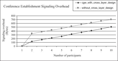
This uses the entry of route topology. In most of the routing protocols of MCNs, there is a route topology stored in an entity of the infrastructure side of the network. The entity may be a BTS (e.g., in reference 66) or a Mobile Switching Center (MSC) (e.g., in reference 21), depending on what type of lower-layer routing protocol is deployed. The idea is to collocate a CGW with the entity where there is a routing topology. In this case, the CGW can periodically acquire the MANET nodes’ information from the routing topology and update its participant location repository. The overhead related to the frequent application-layer location update can then be avoided. For the question of how many CGWs should be deployed, in the conditions of considered environment, one CGW can be deployed per multihop routing area. This will facilitate the signaling routing procedure.
Figure 12.11 depicts performance results of comparing the signaling overheads using and without using CGW optimization. It shows that with the CGW optimization scheme, system introduces much less overhead than the usage of a CGW discovery protocol in application layer.
Super-member Selection Based on Signal Power Scheme.
The signal power entry is used. A node with the highest signal power has a higher priority to be a super-member. The signal power value is provided by the physical layer. In most cases, signal power is influenced by the distance between a BTS and an MS, and thus a higher signal power may reflect a short path between a super-member and the CGW. Also, it is a general case that when a node is physically closer to a BTS, it is less prone to move out of range. This helps to optimize the signaling route and improve cluster stability.
12.3.4.4 Interoperability Analysis.
The interaction between parties with and without cross-layer optimizations is a complex issue. Some of the optimizations may cause interoperability problems while others may not, depending on local versus global effect of an optimization scheme. A local effect does not cause an interoperability issue, while the global effect causes an issue if both parties make a decision at the same time and their decisions are in conflict. Within the optimization schemes introduced thus far, those that may cause serious interoperability problems are the super-member election optimization schemes. In a cluster, more than one party may be selected as a super-member based on different rules. This is not allowed in the cluster scheme. One solution is that whenever a super-member detects another super-member in the same cluster, it checks if its cross-layer information is active. The super-member without active cross-layer information changes itself to a cluster member.
12.4 SUMMARY
In this chapter, we have presented signaling architectures for conferencing in 4G. We reviewed the conferencing protocols in legacy networks such as 3G, and we also introduced the proposals for new network and scenarios: MANETs and integrated MANETs/3G networks.
Another important content of this chapter is the optimization of the signaling schema. We characterized and discussed the signaling issues and provided a solution, optimization architecture, and schema, which are based on cross-layer design.
Notes
1 Sections 12.2.1.2–12.2.1.4 are taken from reference 55. Copyright © IEEE 2009.
2 Sections 12.2.2.2.1, 12.2.2.2.2, and 12.2.2.3 are taken from reference 56. Copyright © IEEE 2006.
3 Sections 12.3.1 to 12.3.4.4 are taken from reference 58. Copyright © IEEE 2008.
REFERENCES
1. Y. K. Kim and R. Prasad, 4G Roadmap and Emerging Communication Technologies, Artech House, Norwood, MA, 2005.
2. Wireless World Research Forum (WWRF), Technologies for the Wireless Future, Vol. 3, K. David, (ed.), John Wiley & Sons, Hoboken, NJ, 2008.
3. U. Varshney and R. Jain, Issues in emerging 4G wireless networks, IEEE Computer, Vol. 34, No. 6, pp. 94–96, June 2001.
4. Jennifer J. –N. Liu and I. Chlamtac, Mobile ad hoc networking with a view of 4G wireless: Imperatives and challenges, Mobile Ad Hoc Networking, Wiley-IEEE Press, Hoboken, NJ, 2004.
5. M. Conti, Body, personal, and local ad hoc wireless networks, in Handbook of Ad Hoc Networks, M. Ilyas (ed.), Chapter I, CRC Press, New York, 2003.
6. B. Xu, S. Hischks, and B. Walke, The role of ad hoc networking in future wireless communications, in Proceedings of ICCT, 2003.
7. IEEE 802.15.3 TM, Part 15.3: Wireless Medium Access Control (MAC) and Physical Layer (PHY) Specifications for High Rate Wireless Personal Area Networks (WPANs), IEEE Computer Society, Washington, DC, 2003.
8. C. Bisdikian, An overview of bluetooth wireless technology, IEEE Commun. Mag. pp. 86–94, December 2001.
9. IEEE std 802.11, Wireless LAN Medium Access Control (MAC) and Physical Layer (PHY) Specifications, IEEE Communications Society, New York, 1999.
10. G. V. Zaruba and S. K. Das, Off-the-shelf enablers of ad hoc networks, in Mobile Ad Hoc Networking, Wiley-IEEE Press, Hoboken, NJ, 2004.
11. J. L. Burbank and W. T. Kash, IEEE 802.16 broadband wireless technology and its application to the military problem space, in IEEE MILCOM 2005, Vol. 3, 17–20 October 2005, pp. 1905–1911.
12. M. Sherman et al., A PMP-friendly MANET networking approach for WiMAX/IEEE 802.16, in IEEE MILCOM 2006, 23–25 October 2006, pp. 1–7.
13. C. Perkins, E. Belding-Royer, and S. Das, Ad Hoc On-Demand Distance Vector (AODV) Routing, RFC 3561, July 2003.
14. T. Clausen and P. Jacquet (eds.), Optimized Link State Protocol (OLSR), RFC 3626, October 2003.
15. R. Ofier, F. Templin, and M. Lewis, Topology Dissemination Based on Reserve-Path Forwarding (TBRPF), RFC 3684, February 2004.
16. D. Johnson,Y. Hu, and D. Maltz, The Dynamic Source Routing Protocol (DSR) for Mobile Ad Hoc Networks for IPv4, RFC 4728, February 2007.
17. Y. Lin and Y. Hsu, Multihop cellular: A new architecture for wireless communication, IEEE INFOCOM 2002, Vol. 3, pp. 1273–1282, 2002.
18. H. Wu, C. Qiao, S. De, and O. Tonguz, Integrated cellular and ad hoc relaying systems: iCAR, IEEE JSAC, Vol. 19, pp. 2105–2115, 2001.
19. H. Luo et al., UCAN: A unified cellular and ad-hoc network architecture, in Procedings, ACM Mobicom, September 2003.
20. Z. Dawy, S. Davidovic, and I. Oikonomidis, Coverage and capacity enhancement of CDMA cellular system via multihop transmission, IEEE Globecom, pp. 1147–1151, 2003.
21. H. Lee and C. Lee, An integrated multi-hop cellular data network, in IEEE Vehicle Technology Conference, Vol. 4, pp. 2232–2236, 2003.
22. Y. Liu et al., Integrated radio resource allocation for multihop cellular networks with fixed relay stations, IEEE JSAC, Vol. 24, pp. 2137–2146, November 2006.
23. G. Kannan, S. N. Merchant, and U. B. Desai, Access mechanism for multihop cellular networks, IEEE VTC-2007, pp. 279–283, 2007.
24. A. Kusuma, L. Andrew, and S. V. Hanly, On routing in CDMA multihop cellular networks, IEEE Globecom, pp. 3063–3067, 2004.
25. Y. Wu, K. Yang, and J. Zhang, An adaptive routing protocol for an integrated cellular and ad-hoc network with flexible access, in ACM IWCMC’06, Vancouver, pp. 263–268, 2006.
26. A. R. Wolff and C. Lee, Large scale routing in a multi-hop cellular network using a radial geometric approach, IEEE WCNC, pp. 4446–4451, 2007.
27. P. P. Lam and S. C. Liew, Nested network mobility on the multihop cellular network, IEEE Commun. Mag., Vol. 45, No. 9, pp. 100–104, September 2007.
28. D. Cavalcanti, D. Agrawal, C. Cordeiro, B. Xie, and A. Kumar, Issues in Integrating Cellular Networks, WLANs and MANETs: A Futuristic heterogeneous Wireless Network, IEEE Wireless Communications, June 2005.
29. H. Dommel and J. Aceves, Floor control for multimedia conferencing and collaboration, ACM Multimedia Systems Mag., Vol. 5, No. 1, pp. 23–38, 1997.
30. H. Schulzrinne and J. Rosenberg, Signaling for internet telephony, in Procedings, 6th International Conference on Network Protocols, IEEE Computer Society, Washington, DC, pp. 298–307, 1998.
31. J. Rosenberg, A Framework for Conferencing with the Session Initiation Protocol (SIP), IETF RFC 4353, February 2006.
32. ITU-T Recommendation T.120, Data Protocols for Multimedia Conferencing, ITU-T, July 1997.
33. E. M. Schooler and S. L. Casner, An architecture for multimedia connection management, in Proceedings, IEEE 4th Comsoc International Workshop on Multimedia Communications, MM’92, pp. 271–274, Monterey.
34. S. Shenker, A. Weinrib, and E. Schooler, Managing shared ephemeral teleconferencing state: Policy and mechanism, IETF Internet draft, July 1995.
35. M. Handley, I. Wakeman, and J. Crowcroft, The conference control channel protocol (CCCP): A scalable base for building conference control applications, in Proceedings of ACM SIGCOMM’95, Boston, August 1995.
36. C. Bormann, J. Ott, and C. Reichert, Simple conference control protocol, IETF Internet draft, December 1996.
37. O. Novo, G. Gamarillo, D. Morgan, and R. Even, A common conference information data model for centralized conferencing (XCON), IETF Internet draft, April 2006.
38. H. Khartabil, P. Koskelainen, and A. Niemi, The conference policy control protocol, IETF Internet draft < draft-ietf-xcon-cpcp-01 >, 2004.
39. G. Gamarillo, J. Ott, and K. Drage, The Binary Floor Control Protocol (BFCP), IETF RFC 4582, November 2006.
40. H. Schulzrinne et. al., RTP: A Transport Protocol for Real-Time Applications, IETF RFC3550, July 2003.
41. H. Schulzrinne and S. Casner, RTP Profile for Audio and Video Conferences with Minimal Control, IETF RFC 3551, July 2003.
42. C. Groves el al., Gateway Control Protocol Version 1, IETF RFC 3525, June 2003.
43. H.248.1, Gateway Control Protocol: Version 3, ITU-T, September 2005.
44. J. Van Dyke, E. Burger, and A. Spitzer, Media Server Control Markup Language (MSCML) and Protocol, IETF RFC 5022, September 2007.
45. H.323 series, ITU-T Recommendations, Geneva 2003.
46. Rosenberg et al., SIP: Session Initiation Protocol, RFC 3261, June 2002.
47. H. Liu and P. Mouchtaris, Voice Over IP Signaling: H.323 and Beyond, IEEE Commun. Mag., Vol. 38, No. 10, pp. 142–148, October 2000.
48. H. Schulzrinne and J. Rosenberg, The session initiation protocol: internet centric signaling, IEEE Commun. Mag., Vol. 38, No. 10, pp. 134–141, October 2000.
49. 3GPP TS 24.147, V8.2.0, Conferencing using the IP multimedia (IM) core network (CN) subsystem, Stage 3, Release 8, December 2008.
50. P. Koskelainen, H. Schulzrinne, and X. Wu, A SIP-based conference control framework, in ACM NOSSDAV ’02, May 2002.
51. A. Uyar, W. Wu, H. Bulut, and G. Fox, Service-oriented architecture for a scalable videoconferencing system, in ICPS ’05, 11–14 July 2005, pp. 445–448.
52. H. J. Wang et al., Iceberg: An Internet core network architecture for integrated communications, IEEE Personal Commun., Vol. 7, No. 4, pp. 10–19, August 2000.
53. M. Kelley, Distributed Multipoint Conferences Using SIP, IETF Internet draft, March 8, 2000.
54. H. Khlifi, A. Agarwal, and J.-C. Gregoire, A framework to use SIP in ad-hoc networks, in Electrical and Computer Engineering, IEEE CCECE 2003, Canadian Conference on 4–7 May 2003, pp. 985–988 Vol. 2.
55. C. Fu, R. Glitho, and F. Khendek, Signaling for multimedia conferencing in standalone mobile ad hoc network, IEEE Trans. Mobile Computing, Vol. 8, issue. 7, pp. 991–1005, 2009.
56. C. Fu, F. Khendek, and R. Glitho, Signaling for multi-media conferencing in 4G: The case of integrated 3G/MANETs, IEEE Commun. Mag., Vol. 44, No. 8, pp. 90–99, August 2006.
57. S. Helal, N. Desai, V. Verma, and C. Lee, Konark—A service discovery and delivery protocol for ad-hoc networks, in IEEE WCNC 2003, Vol. 3. 16–20 March 2003, pp. 2107–2113.
58. C. Fu, R. Glitho, and F. Khendek, A cross-layer architecture for signaling in multihop cellular networks, IEEE Commun. Mag., Vol. 46, No. 9, pp. 174–182, September 2008.
59. M. Chatterjee, S. K. Das, and D. Turgut, An on-demand weighted clustering algorithm (WCA) for ad hoc networks, in IEEE GLOBECOM’00, Vol. 3, 27 November–1 December 2000, pp. 1697–1701.
60. Srivastava and M. Motani, Cross-layer design: a survey and the road ahead, IEEE Commun. Mag., December 2005.
61. E. Setton et al., Cross-layer design of ad hoc networks for real-time video streaming, IEEE Wireless Commun., Vol. 12, issue 4, pp. 59–65, August 2005.
62. Q. Wang and M. A. Abu-Rgheff, Cross-layer signaling for next-generation wireless systems, in Proceding IEEE WCNC, March 2003.
63. M. Conti, G. Maselli, G. Turi, and S. Giordano, Cross-layering in mobile ad hoc network design, IEEE Computer, Vol. 37, No. 2, pp. 48–51, February 2004.
64. R. Winter, J. H. Schiller, N. Nikaein, and C. Bonnet, CrossTalk: Cross-layer decision support based on global knowledge, IEE Commun. Mag., pp. 93–99, January 2006.
65. R. T. Raisinghani and S. Lyer, Cross-layer feedback architecture for mobile device protocol stacks, IEEE Commun. Mag., pp. 85–92, January 2006.
66. H. Choi and D. Cho, Fast and reliable route discovery protocol considering mobility in multihop cellular networks, in IEEE Vehicle Technology Conference, Vol. 2, 2006, pp. 886–890.
67. G. Kannan, S. N. Merchant, and U. B. Desai, Cross layer routing for multihop cellular networks, in Advanced Information Networking and Applications Workshops, Vol. 2, May 2007, pp. 165–170.