10 Working with Wireless Flash
As I mentioned in the last chapter, one of the chief objections to the use of electronic flash is the stark, flat look of direct/on-camera flash. But as flash wizard Joe McNally, author of The Hotshoe Diaries, has proven, small flash units can produce amazingly creative images when used properly.
The key to effective flash photography is to get the flash off the camera, so its illumination can be used to paint your subject in interesting and subtle ways from a variety of angles. But, sometimes, using a cable to liberate your flash from the accessory shoe isn’t enough. Nor is the use of just a single electronic flash always the best solution. What we really have needed is a way to trigger one—or more—flash units wirelessly, giving us the freedom to place the electronic flash anywhere in the scene and, if our budgets and time allow, to work in this mode with multiple flashes.
Wireless Evolution
Some Canon “enthusiast”-level cameras with a built-in flash include internal wireless triggering capabilities using the on-camera flash. Because more advanced cameras like the R7 don’t have a flash to serve as a wireless sender (master), we must rely on using other flash units or add-ons to trigger our Speedlites wirelessly. Fortunately, most users of this camera are advanced photographers and can generally abide the equipment requirements that accompany useful wireless capabilities.
It’s not possible to cover every aspect of wireless flash in one chapter. There are too many permutations involved. For example, you can use an external flash, or the ST-E2 optical transmitter (or STE3-RT radio transmitter) as the sender. You may have one external “receiver” flash or use several. It’s possible to control all your wireless flash units as if they were one multi-headed flash, or you can allocate them into “groups” that can be managed individually. You may select one of several “channels” to communicate with your strobes (or any of multiple wireless IDs when using radio-controlled units like the EL-1 or 600EX II-RT). These are all aspects that you’ll want to explore as you become used to working with the amazing wireless capabilities.
What I hope to do in this chapter is provide the introduction to the basics that you won’t find in the other guidebooks, so you can learn how to operate the wireless capabilities quickly, and then embark on your own exploration of the possibilities.
YOUR STEPS MAY VARY
This chapter is intended to teach you the basics of wireless flash: why to use it, how a dedicated flash or add-on controller can be used to trigger and manipulate additional units, and what lighting ratios, channels, and groups are. I’m going to provide instructions on getting set up with wireless flash, but, depending on what flash unit you’re working with (and how many you have), your specific steps may vary. The final authority on working with wireless flash has to be the manual furnished with your flash unit.
Elements of Wireless Flash
Here are some of the key concepts to electronic flash and wireless flash that I’ll be describing in this chapter. Learn what these are, and you’ll have gone a long way toward understanding how to use wireless flash. You need to understand the various combinations of flashes that can be used, how they can be controlled individually and together, and why you might want to use multiple and off-camera flash units. I’m going to address all these points in this section.
Flash Combinations
Your attached on-camera external flash can be used alone, or, if it has the capability to serve as a master or controller flash (not all Canon Speedlites do), now called sender in Canonspeak, in combination with other, external remote flash units (now called receivers by Canon). Here’s a quick summary of the permutations available to you.
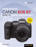
◼ On-camera flash used alone. Your on-camera flash can function as the only flash illumination used to take a picture. In that mode, the flash can provide the primary illumination source (the traditional “flash photo”) with the ambient light in the scene contributing little to the overall exposure. (See Figure 10.1, left.) Or, the on-camera flash can be used in conjunction with the scene’s natural illumination to provide a balanced lighting effect. (See Figure 10.1, center.) In this mode, the flash doesn’t overpower the ambient light, but, instead, serves to supplement it. Finally, the on-camera flash can be used as a “fill” light in scenes that are illuminated predominantly by a natural main light source, such as daylight. In this mode, the flash serves to brighten dark shadows created by the primary illumination, such as the glaring daylight in Figure 10.1, right.
◼ On-camera flash used simultaneously with off-camera flash. You can use the off-camera flash as a main light and supply fill light from the on-camera flash to produce interesting effects and pleasing portraits.
◼ On-camera flash used as a trigger only for off-camera flash. Use the on-camera wireless flash controller to command single or multiple Speedlites for studio-like lighting effects, without having the flash contribute to the exposure itself.

Figure 10.1 On-camera flash alone (left), as a supplement (center), and for fill flash (right).
Controlling Flash Units
There are multiple ways of controlling flash units, both through direct or wired connections and wirelessly. Here are the primary methods used:
◼ Direct connection. The on-camera flash, of course, is directly connected to the camera, and triggered electronically when a picture is taken. External flash units can also be controlled directly by linking them to a camera with a dedicated flash cord that in turn attaches to the accessory hot shoe, such as the Canon OC-E3 EOS Dedicated TTL off-camera shoe cord.
When used in these modes, the camera has full communication with the flash, which can receive information about zoom lens position, correct exposure required, and the signals required to fire the flash. You can also plug a non-dedicated strobe, such as studio flash units, into an adapter plugged into the R7’s hot shoe. Either PC/X connection is “dumb” and conveys no information other than the signal to fire.
◼ Dedicated wireless optical signals. In this mode, external flash units communicate with the camera through a pre-flash, which is used to measure exposure prior to the “real” flash burst an instant later. The pre-flashes can also wirelessly send information from the camera to the flash unit, to determine the duration of the burst to achieve the desired exposure. The pulses also can be used to adjust zoom head position (if the flash has that feature). In the case of Canon flash units, the pre-flash information is sent and received as visible light, sent so quickly just before the main burst that you may not be able to distinguish them from the “real” flash.
◼ Dedicated wireless infrared signals. Some devices, such as the Canon ST-E2 Speedlite Transmitter, can communicate with dedicated flash units through infrared signals—much like the remote control of your television. (And, also like your TV remote, the IR signal can bounce around the room somewhat, but you more or less need a line-of-sight connection for the communication to work properly.) (See Figure 10.2, left, for front and back views.) The transmitter attaches to the accessory shoe or is connected to the accessory shoe through a dedicated cable. It was an option for wireless flash for Canon cameras prior to the EOS 7D (and later models with an in-camera wireless controller), as well as for Canon cameras that have no flash unit at all (such as the EOS 1D and 5D series). Although the ST-E2 costs about $220, it’s still less expensive than using a unit like the 600EX II as a sender/controller, particularly when on-camera flash is not desired. However, the EL-100 flash, priced at about $200, may be an even better budget choice as a controller, because it gives you the option to use it as a conventional on-camera or off-camera flash.

Figure 10.2 The ST-E2 infrared transmitter (left) and ST-E3-RT radio transmitter (right).
◼ Canon and third-party IR and radio transmitters. The EL-1, 600EX-RT/600EX II-RT, 430EX III-RT, and ST-E3-RT from Canon can communicate as sender flash units using radio signals. The EL-1, 600EX-RT, and 600EX II-RT can also serve as a sender optical flash, and as a radio or optical receiver, while the 430 EX III-RT functions as a receiver only in optical mode. The ST-E3-RT, shown at right in Figure 10.2, functions only as a radio trigger and cannot communicate with flashes that recognize only optical signals. It’s priced at about $300.
In addition, some excellent wireless flash controllers that use IR or radio signals to operate external flash units are available from sources like Godox, PocketWizard, and RadioPopper. One advantage some of these third-party units have is the ability to dial in exposure/output adjustments from the transmitter mounted on the accessory shoe of the camera.
◼ Optical receiver units. A relatively low-tech/low-versatility option is to use optical receiver units that trigger the off-camera flash units when they detect the firing of the main flash. Receiver triggers are inexpensive, but dumb: they don’t allow making any adjustments to the external flash units and are not compatible with the E-TTL II exposure system. Moreover, you should make sure that the receiver trigger responds to the main flash burst only, rather than a pre-flash, using a so-called digital mode. Otherwise, your receiver units will fire before the main flash, and not contribute to the exposure.
Why Use Wireless Flash?
Canon’s wireless flash system gives you a number of advantages that include the ability to use directional lighting, which can help bring out detail or emphasize certain aspects of the picture area. It also lets you operate multiple strobes; with models like the old favorite 580EX II that’s as many as four flash units in each of three groups, or twelve in all (although most of us won’t own 12 Canon Speedlites). With the EL-1, 600EX-RT/600EX II-RT, and 430EX III-RT, which also have radio control in addition to optical transmission, you can control many more flash units optically, but only 15 radio-controlled Speedlites, in five different groups.
You can set up complicated portrait or location lighting configurations. Since the two top Canon Speedlites pump out a lot of light for a shoe-mount flash, a set of these units can give you near studio-quality lighting. Of course, the cost of these high-end Speedlites approaches or exceeds that of some studio monolights—but the Canon battery-powered units are more portable and don’t require an external AC or DC power source.
Key Wireless Concepts
There are three key concepts you must understand before jumping into wireless flash photography: channels, groups, and flash ratios. Here is an explanation of each:
◼ Channel controls. Canon’s wireless flash system offers users the ability to determine on which of four possible channels the flash units can communicate. (The pilots, ham radio operators, or scanner listeners among you can think of the channels as individual communications frequencies.) When using optical transmission, the channels are numbered 1, 2, 3, and 4, and each flash must be assigned to one of them. Moreover, in general, each of the flash units you are working with should be assigned to the same channel, because the receiver Speedlites will respond only to a sender flash that is on the same channel.
When using the EL-1, 600EX-RT, or 430EX III-RT in radio control mode, there are 15 different channels, plus an Auto setting that allows the flash to select a channel. In addition, you can assign a four-digit Wireless Radio ID that further differentiates the communications channel your flashes use.
The channel ability is important when you’re working around other photographers who are also using the same system. Photojournalists, including sports photographers, encounter this situation frequently. At any event populated by a sea of “white” lenses, you’ll often find photographers who are using Canon flash units triggered by Canon’s own optical or (now) radio control. Third-party triggers from PocketWizard or RadioPopper are also popular, but Canon’s technology remains a mainstay for many shooters.
Each photographer sets flash units to a different channel so as to not accidentally trigger other users’ strobes. (At big events with more than four photographers using Canon flash and optical transmission, you may need to negotiate.) I use this capability at workshops I conduct where we have two different setups. Photographers working with one setup use a different channel than those using the other setup and can work independently even though we’re at opposite ends of the same large room.
There is less chance of a channel conflict when working with radio control and all radio-compatible Canon flash units. With 15 channels to select from, and almost 10,000 wireless radio IDs to choose from, any overlap is unlikely. (It’s smart not to use a radio ID like 0000, 1111, 2222, etc., to avoid increasing the chances of conflicts. I use the last four digits of my mother-in-law’s social security number.) Remember that you must use either all optical or all radio transmission for all your flash units; you can’t mix and match.
◼ Groups. Canon’s wireless flash system lets you designate multiple flash units in separate groups. There can be as many as three groups with earlier Speedlites like the 580EX II, and newer models like the EL-100, labeled A, B, and C.
With the EL-1, 600EX-RT, 430EX III-RT, and ST-E3-RT, up to five groups (A, B, C, D, and E) can be used with as many as 15 different flash units. All the flashes in all the groups use the exact same channel and all respond to the same sender controller, but you can set the output levels of each group separately. So, Speedlites in Group A might serve as the main light, while Speedlites in Group B might be adjusted to produce less illumination and serve as a fill light. It’s convenient to be able to adjust the output of all the units within a given group simultaneously. This lets you create different styles of lighting for portraits and other shots.
| TIP It’s often smart to assign flash units that will reside to the left of the camera to the A group, and flashes that will be placed to the right of the camera to the B group. It’s easier to adjust the comparative power ratios because you won’t have to stop and think where your groups are located. That’s because the adjustment controls in the menus are always arranged in the same A-B-C left-to-right alignment. For example, if your A group is used as a main light on the left, and the B group as fill on the right, you intuitively know to specify more power to the A group, and less output to the B group. Reserve the C group (if used) to some other purpose, such as background or hair lights. |

◼ Flash ratios. This ability to control the output of one flash (or set of flashes) compared to another flash or set allows you to produce lighting ratios. You can control the power of multiple off-camera Speedlites to adjust each unit’s relative contribution to the image, for more dramatic portraits and other effects.
Which Flashes Can Be Operated Wirelessly?
A particular Speedlite can have one of two functions. It can serve as a sender flash that’s capable of triggering other compatible Canon units that are on the same channel. Or, a Speedlite can be triggered wirelessly as a slave unit that’s activated by a sender, with full control over exposure through the camera’s eTTL flash system. The second function is easy: all current and many recent Canon shoe-mount flash, including the EL-1, 600EX-RT, 580EX II, 470EX AI, 430EX II, 430EX III, 430EX III-RT, EL-100, 320EX, and 270EX II can be triggered wirelessly. In addition, some Speedlites have the ability to serve as a sender flash.
I’m not going to discuss older flash units in this chapter; if you own one, particularly a non-Canon unit, it may or may not function as a receiver. For example, the early Speedlite 380EX lacked the wireless capabilities added with later models, such as the 420EX, 430EX, 430EX II, 430EX III, and 430EX III-RT.
Here’s a quick rundown of current flash capabilities:
◼ Canon Speedlite EL-1 or 600EX-RT/600EX II-RT. These top-of-the-line flashes can function as a sender flash when physically attached to any Canon EOS model, using either optical or radio transmission, and can be triggered wirelessly by another sender flash, such as a compatible EOS model, another EL-1, 600EX-RT/600EX II-RT, or 580EX II, or the ST-E2/ST-E3-RT transmitters.
◼ Canon Speedlite 580EX II. This discontinued flash can function as a sender flash when physically attached to any Canon EOS model and can be triggered wirelessly by an optical (not radio) transmission from another sender flash from a compatible EOS camera, another 580EX II, a 600EX-RT, 600EX II-RT, 430EX III-RT, or the ST-E2 transmitter. (The ST-E3-RT transmitter operates in radio mode only.)
◼ Canon Speedlite 470EX AI. This flash can function only as an optical receiver when used off-camera. It cannot serve as a sender.
◼ Canon Speedlite 430EX III. This sibling of the radio-compatible version described next cannot function as a sender but can be used as a receiver when working with optical triggering technology.
◼ Canon Speedlite 430EX III-RT. This newer flash can function as a sender (in radio mode only) and as a receiver when using both optical and radio technology.
◼ Canon Speedlite 430EX II. This discontinued flash cannot function as a sender, but can be triggered wirelessly by a sender flash, including a compatible EOS camera, a Speedlite 600EX-RT/580EX II, or the ST-E2 transmitters.
◼ Canon Speedlite 320EX. This flash can be triggered wirelessly by a sender flash, including a compatible EOS camera, a 600EX-RT/600EX II-RT, 580EX II, or the ST-E2 transmitter.
◼ Canon Speedlite 270EX II. This flash can be triggered wirelessly by a compatible camera’s sender flash, a 600EX-RT/600EX II-RT, 580EX II, or the ST-E2 transmitter in optical mode.
◼ Canon Speedlite EL-100. This flash can be triggered wirelessly by a compatible camera’s sender flash, a 600EX-RT/600EX II-RT, 580EX II, or the ST-E2 transmitter in optical mode and serve as a sender to trigger other flashes.
You can use any combination of compatible flash units in your wireless setup. You can use an attached 600EX-RT/600EX II-RT, 580EX II, 430EX III-RT, EL-100, or ST-E2/ST-E3-RT as a sender, with any number of 600EX-RT, 580EX II, 470EX AI, 430EX III, 430EX III-RT, EL-100, 430EX II, 320EX, or 270EX II units (or older compatible Speedlites not discussed in this chapter) as wireless receivers. I’ll get you started assigning these flash to groups and channels later on.
Setting Up a Sender/Controller Flash
The first step in working with wireless flash is to set up one unit (either a flash or controller) as the sender. You can mount a Speedlite EL-100, 580EX, 580EX II, EL-1, or 600EX-RT/600EX II-RT to your camera, which can serve as the sender unit, transmitting E-TTL II optical signals to one or more off-camera Speedlite receiver units. The sender unit can have its flash output set to “off” so that it controls the remote units with the pre-flash but omitting the main flash so the sender unit does not contribute any illumination of its own to the exposure. This is useful for images where you don’t want noticeable flash illumination coming in from the camera position. The next sections explain your options for setting up a sender unit for fully automatic, E-TTL II exposure. You can also use manual exposure instead of E-TTL II automatic exposure in wireless mode. Setting up your sender flash for manual operation is beyond the scope of this introductory wireless chapter.
Using a Speedlite as an Optical Sender
Here are the steps to follow with the on-flash controls to set up and use compatible Speedlites as a camera-mounted sender unit for automatic exposure. (The EL-100 is set up as a sender using the Flash Function settings rather than controls on the flash; when you activate Wireless functions, Channel, Group, and Flash Ratio adjustments become available.) For each individual flash unit described below, check your flash’s manual if you have any questions about particular button location.
EL-1
1. Press the joystick on the flash to the left to select flash functions.
2. Highlight Optical (lightning bolt symbol on the flash LCD) sender using the joystick or by rotating the Select Dial.
3. Press the joystick vertically to confirm.
4. Use the menu system to control and make changes to RATIO, output, and other options on the sender and receiver units.
600EX-RT/600EX II-RT
1. Press the Wireless button repeatedly until the LCD panel indicates you are in optical wireless sender mode.
2. Press MODE to cycle through the ETTL, M, and Multi modes.
3. Use the menu system to control and make changes to RATIO, output, and other options on the sender and receiver units.
580EX II
1. Press and hold the ZOOM button to bring up the wireless options. Use the Select Dial to cycle through the OFF, SENDER on, and RECEIVER on options. Select and confirm SENDER on.
2. Press MODE to cycle through the ETTL, M, and Multi modes.
3. Press the ZOOM button repeatedly to cycle through the following options: Flash zoom, RATIO, CH., and flash emitter ON/OFF. Use the Select Dial and Select/SET button to make any changes to these options.
4. Use the Select/SET button to select and confirm the output power settings when using Manual and Multi modes, or to use FEC or FEB when in ETTL mode.
580EX
1. Slide the OFF/SENDER/RECEIVER wireless switch near the base of the unit to SENDER.
2. Press MODE to cycle through the ETTL, M, and Multi modes.
3. Press the ZOOM button repeatedly to cycle through the following options: Flash zoom, RATIO, CH., and flash emitter ON/OFF. Use the Select Dial and Select/SET button to make any changes to these options.
4. Use the Select/SET button to select and confirm the output power settings when using Manual and Multi modes, or to use FEC or FEB when in ETTL mode.
Using the ST-E2 Transmitter as Sender
Canon’s Speedlite Transmitter (ST-E2) is mounted on the camera’s hot shoe and provides a way to control one or more Speedlites and/or units assigned to Groups A and B. The ST-E2 does not provide any flash output of its own and will not trigger units assigned to Group C. It has the following features and controls:
◼ Transmitter. Located on the top front of the unit, the transmitter emits E-TTL II pulses through an infrared filter.
◼ AF-assist beam emitter. Just below the transmitter, the AF-assist beam emitter works similarly to the Speedlite 430EX II and higher models.
◼ Battery compartment. The ST-E2 uses a 6.0V 2CR5 lithium battery. The battery compartment is accessed from the top of the unit.
◼ Lock slider and mounting foot. The lock slider is located on the right side of the unit when facing the front. Sliding it to the left lowers the lock pin in the mounting foot (located on the bottom of the unit) to secure it to the camera’s hot shoe.
◼ Back panel. The rear of the unit features several indicators and controls:
• Ratio indicator. A series of red LED lights indicating the current A:B ratio setting.
• Flash ratio control lamp. A red LED that lights up when flash ratio is in use.
• Flash ratio setting button. Next to the flash ratio control lamp. Press this button to activate flash ratio control.
• Flash ratio adjustment buttons. Two buttons with raised arrows (same color as buttons) pointing left and right. Use these to change the A:B ratio setting.
• Channel indicator. The channel number in use (1–4) glows red.
• Channel selector button. Next to the channel indicator. Press this button to select the communication channel.
• High-speed sync (FP flash) indicator. A red LED that glows when high-speed sync is in use.
• High-speed sync button. Press this button to activate/deactivate high-speed sync.
• ETTL indicator. A red LED that glows when E-TTL II is in use.
• Off/On/HOLD switch. Slide this switch to turn the unit off, on, or on with adjustments disabled (HOLD). The ST-E2 will power off after approximately 90 seconds of idle time. It will turn back on when the shutter button or test transmission button is pressed.
• Pilot lamp/Test transmission button. This lamp works similarly to the Speedlite pilot lamp/test buttons. The lamp glows red when ready to transmit. Press the lamp button to send a test transmission to the receiver units.
• Flash confirmation lamp. This lamp glows green for about three seconds when the ST-E2 detects a good flash exposure.
Here are the steps to follow to set up and use the ST-E2 transmitter (shown previously at left in Figure 10.2) as a camera-mounted sender unit:
1. Mount the ST-E2 unit on your camera.
2. Make sure both the ST-E2 unit and your camera are powered on.
3. Make sure the receiver units are set to E-TTL II, assigned to the appropriate group(s), and that all units are operating on the same channel.
4. If you’d like to set a flash ratio between Groups A and B, press the flash ratio setting button and flash ratio adjustment buttons to select the desired ratio. Press the high-speed sync button to use high-speed sync (often helpful with outdoor shooting).
Using the Speedlite EL-1 as Radio Sender
The Speedlite EL-1 can serve as the sender unit when mounted to your camera, transmitting radio signals to one or more off-camera Speedlite EL-1, 430EX III-RT, or 600EX-RT/600EX II-RT receiver units. The sender unit can have its flash output set to “off” so that it controls the remote units without contributing any flash output of its own to the exposure. This is useful for images where you don’t want noticeable flash illumination coming in from the camera position. Just follow these steps:
1. Press the joystick on the flash to the left to select flash functions.
2. Highlight Radio (wireless antenna symbol on the flash LCD) sender using the joystick or by rotating the Select Dial.
3. Press the joystick vertically to confirm.
4. Use the menu system to control and make changes to RATIO, output, and other options on the sender and receiver units.
Using the Speedlite 600EX-RT/600EX II-RT as Radio Sender
The Speedlite 600EX-RT/600EX II-RT can serve as the sender unit when mounted to your camera, transmitting radio signals to one or more off-camera Speedlite 600EX-RT/600EX II-RT receiver units. The sender unit can have its flash output set to “off” so that it controls the remote units without contributing any flash output of its own to the exposure. This is useful for images where you don’t want noticeable flash illumination coming in from the camera position.
Here are the steps to follow to set up and use a Speedlite 600EX-RT/600EX II-RT as a camera-mounted sender unit for radio wireless E-TTL II operation:
1. Mount the Speedlite 600EX-RT/600EX II-RT to your camera.
2. Make sure the 600EX-RT sender units, receiver units, and the camera are powered on.
3. Set the camera-mounted unit to radio wireless SENDER mode. Press the Wireless button until the LCD panel indicates you are on radio wireless sender mode.
4. Set the receiver 600EX-RT/600EX II-RT or 430EX III-RT units to radio wireless RECEIVER mode. For each 600EX-RT unit, press the Wireless button until the LCD panel indicates you are on radio wireless receiver mode. For each 430EX III-RT receiver, press the left directional key and rotate the Select Dial until Receiver appears on the LCD. Then press the Select button to confirm.
5. Confirm that all units are set to E-TTL II, assigned to the appropriate group(s), and that all units are operating on the same channel and ID number. The LINK lamps on all units should glow green.
Using the Speedlite 430EX III-RT as Radio Sender
The Speedlite 430EX III-RT can serve as a radio sender unit to trigger another 430EX III-RT or a 600EX-RT flash. Just follow these steps:
1. Press the left directional key on the Select Dial. It’s marked with a lightning bolt symbol.
2. Rotate the Select Dial until SENDER appears on the LCD.
3. Press the Select button in the center of the Select Dial.
4. Set any 600EX-RT or 430EX III-RT units that you will be using as receivers to the Receiver mode.
• For the 600EX-RT, press the Wireless button until the LCD panel indicates you are in radio wireless receiver mode.
• For any 430EX III-RT receivers, press the left directional key and rotate the Select Dial until Receiver appears on the LCD. Then press the Select button to confirm.
5. Repeat Step 4 for any additional receiver units.
6. When sender and receivers are communicating, the LINK lamps on all units will glow green.
Using the ST-E3-RT as Radio Sender
The ST-E3-RT transmitter can be mounted to the camera’s hot shoe and used as a sender controller to one or more receiver Speedlite 600EX-RT units. The ST-E3-RT and the 600EX-RT share essentially the same radio control capabilities except that the ST-E3-RT does not produce flash, provide AF-assist, or otherwise emit light and is therefore incapable of optical wireless transmission.
The layout of the ST-E3-RT’s control panel is virtually identical to the 600EX-RT. So is the menu system and operation, except that, as stated earlier, it will only operate as a radio wireless transmitter. Here are the steps to follow to set up and use the ST-E3-RT transmitter as a camera-mounted sender unit for radio wireless E-TTL II operation:
1. Mount the ST-E3-RT unit on your camera.
2. Make sure both the ST-E3-RT unit and your camera are powered on.
3. Set the receiver 600EX-RT or 430EX III-RT units to radio wireless RECEIVER mode. For each 600EX-RT unit, press the Wireless button until the LCD panel indicates you are on radio wireless receiver mode. For each 430EX III-RT receiver, press the left directional key and rotate the Select Dial until Receiver appears on the LCD. Then press the Select button to confirm.
4. Confirm that all units are set to E-TTL II, assigned to the appropriate group(s), and that all units are operating on the same channel and ID number. The LINK lamps on all units should glow green.
The ST-E3-RT controls receiver units as described earlier in the section, “Using the Speedlite 600EX-RT/600EX II-RT as Radio Sender.”
Setting Up a Receiver Flash
The whole point of working wirelessly is to have a sender flash/controller trigger and adjust one or more receiver flash units. So, once you’ve defined your sender flash, the next step is to switch your remaining Speedlites into receiver mode. That’s done differently with each particular Canon Speedlite.
◼ Speedlite EL-1. Use the joystick on the flash as described above and choose Optical Receiver or Wireless Receiver.
◼ Speedlite 600EX-RT/600EX II-RT. Press the Wireless button repeatedly until the LCD panel indicates that the unit is in optical wireless receiver mode or radio wireless receiver mode. In this mode, the 600EX-RT is assigned a flash mode by the sender transmitter, either a flash or ST-E2 or ST-E3-RT.
◼ Speedlite 580EX II. Press and hold the ZOOM button until the wireless setting options appear. Use the Select Dial and Select/SET button to select and confirm that wireless is on and in receiver mode.
◼ Speedlite 430EX III/430EX III-RT. For each 430EX III-RT receiver, press the left directional key and rotate the Select Dial until Receiver appears on the LCD. Then press the Select button to confirm.
◼ Speedlite 430EX II. Press and hold the ZOOM button for two seconds or more until the wireless setting options appear. Use the Select Dial and Select/SET button to select and confirm that wireless is on and in receiver mode.
◼ Speedlite 320EX. This flash has an On/Off/Receiver switch at the lower left of the back panel. In Receiver mode, you can use the flash’s C.Fn-10 setting to tell the unit to power down after either 10 or 60 minutes of idle time. That can help preserve the 320EX’s batteries. The unit’s C.Fn-11 setting can be set to allow the sender transmitter to “wake” a sleeping 320EX after your choice of within 1 hour or within 8 hours. Note that the C.Fn settings of the 320EX and 270EX II (described next) can be set only while the Speedlites are connected to the camera with the hot shoe.
◼ Speedlite 270EX II. This flash has an Off/Receiver/On switch. If left on and idle, the 270EX II will power itself off after approximately 90 seconds. C.Fn-1 can be used to disable auto power off. As with the 320EX, in Receiver mode, you can use the flash’s C.Fn-10 setting to tell the unit to power down after either 10 or 60 minutes of idle time. The unit’s C.Fn-11 setting can be set to allow the sender transmitter to “wake” a sleeping unit after your choice of within 1 hour or within 8 hours.
◼ Speedlite EL-100. Using this flash as a remote is ridiculously easy. Set the Receiver switch on the back of the unit to the same channel used by the sender and rotate the mode dial to the appropriate Group (usually A).
Choosing a Channel
In optical mode, Canon’s wireless flash system can work on any of four channels, so if more than one photographer is using the Canon system, each can set his gear to a different channel so they don’t accidentally trigger each other’s strobes. You need to be sure all of your gear is set to the same channel. Selecting a channel is done differently with each particular flash model. The EL-100 is the easiest in this regard: just slide the Receiver switch to the Channel you want to use.
The ability to operate flash units on a particular channel isn’t really important unless you’re shooting in an environment where other photographers are also using the Canon wireless flash system. If the system only offered one channel, then each photographer’s wireless flash controller would be firing every Canon flash set for wireless operation. By having four channels available, the photographers can coordinate their use to avoid that problem. Such situations are common at sporting events and other activities that draw a lot of shooters.
It’s always a good idea to double-check your flash units before you set them up to make sure they’re all set to the same channel, and this should also be one of your first troubleshooting questions if a flash doesn’t fire the first time you try to use it wirelessly.
You do this as follows:
1. Set flash units to the channel you want to use for all your groups. Before you use the camera’s controls to configure your flash exposures, you must first make adjustments on the external Speedlite. Each flash unit may use its own procedure for setting that strobe’s channel. Consult your Speed-lite’s manual for instructions. With the 580EX II, press the Zoom button repeatedly until the CH. Indicator blinks, then rotate the control dial to select Channel 1, 2, 3, or 4. Press the control dial center button to confirm. With the 600EX-RT/600EX II-RT, press Fn Button 4 until Menu 2 appears, then press Fn Button 1 to select a channel. The EL-1 allows you to set the channel (plus groups, and all other settings) from the integrated LCD menu on the flash itself using the joystick and Select wheel.
2. Activate wireless operation. From the External Speedlite Control entry in the Shooting 1 menu, navigate to the Flash Function Settings choice, Flash Functions. Highlight the second icon from the left in the top row (as seen in Figure 10.3, left) and press SET. Then choose Wireless: Optical Transmission from the screen that appears (see Figure 10.3, right). Press SET to confirm and exit.

Figure 10.3 You can choose the Channel, Groups, and other parameters from the Flash Functions screen (left); activate wireless functions (right).
3. Navigate to the camera’s channel selection option. Navigate to the Channel Setting (highlighted in red at left in Figure 10.3) and push the SET button.
4. Select the channel your flashes are set to. You can then use the QCD to cycle the channel number from 1 to 4.
5. Enable/disable sender flash firing. The icon to the immediate right of the Channel Setting icon allows you to enable or disable firing of the sender flash. When disabled, the sender flash will still control external flashes wirelessly with a pre-flash burst but won’t contribute to the exposure. This is useful if you want all the illumination to come from your receiver flash units, such as when shooting close-up or macro images, or when you’re simulating a studio flash setup with Speedlites.
6. Double-check to make sure your off-camera flash units are set to the appropriate channel. Your wireless flash units must be set to the same channel as the camera’s wireless flash controller; otherwise, the Speedlites won’t fire.
Working with Groups
With what you’ve already learned, you can shoot wirelessly using your camera’s on-camera flash and one or more external flash units. All these strobes will work together with the camera for automatic exposure using E-TTL II exposure mode. You can vary the power ratio between your on-camera flash and the external units. As you become more comfortable with wireless flash photography, you can even switch the individual external flash units into manual mode and adjust their lighting ratios manually.
But there’s a lot more you can do if you’ve splurged and own two or more compatible external flash units. Canon wireless photography lets you collect individual strobes into groups and control all the Speedlites within a given group together. You can operate as few as two strobes in two groups or three strobes in three groups, while controlling more units if desired. You can also have them fire at equal output settings (A+B+C mode) versus using them at different power ratios (A:B or A:B C modes). Setting each group’s strobes to different power ratios gives you more control over lighting for portraiture and other uses.
This is one of the more powerful options of the EOS wireless flash system. I prefer to keep my Speed-lites set to different groups normally. I can always set the power ratio to 1:1 if I want to operate the flash units all at the same power. If I change my mind and need to make adjustments, I can just change the wireless flash controller and then manipulate the different groups’ output as desired.
Canon’s wireless flash system works with a number of Canon flashes and even some third-party units. I routinely mix a 600EX-RT, 600EX II-RT, 580EX II, 550EX, and 420EX. I control these flash units either with the on-camera external flash or using a Canon ST-E2 Speedlite Transmitter.
The ST-E2 is a hot-shoe mount device that offers wireless flash control for a wide variety of Canon wireless-flash-capable strobes and can even control flash units wirelessly for high-speed sync (HSS) photography. (HSS is described in Chapter 9.) The ST-E2 can only control two flash groups though.
Here’s how you set up groups (for flashes other than the EL-100, which has Group positions on its Mode Dial):
1. Set flash units to the group you want to assign them to. Each flash unit may use its own procedure for setting that strobe’s group. Consult your Speedlite’s manual for instructions.
2. Navigate to the camera’s group selection option. From the External Speedlite Control entry in the Shooting 1 menu, navigate to the Flash Function Settings choice, Flash Functions. Navigate to the Group setting (located just below the Channel and Sender Flash Firing options) and push the SET button.
3. Select the group configuration you want. You can then use the QCD to cycle to select ALL, A:B, or A:B C. If you’re using the 600EX-RT/600EX II-RT in radio control mode, you can also activate Groups D and E.
4. Double-check to make sure your flash units are set to the appropriate channel. Your wireless flash units must be set to the same channel as the camera’s wireless flash controller; otherwise, the Speed-lites won’t fire.
Ratio Control
By default, all the flashes in each group will fire at full power. However, for more advanced lighting setups, you can select lighting ratios.
Your on-camera sender flash and your wireless receiver flash units have their own individual oomph—how much illumination they put out. This option lets you choose the relationship between these units, a power ratio between your on-camera flash and your wireless flash units—the relative strength of each. That ability can be especially useful if you want to use the on-camera flash for just a little fill light, while letting your off-camera units do the heavy work.
Having the ability to vary the power of each flash unit or group of flash units wirelessly gives you greater flexibility and control. Varying the light output of each flash unit makes it possible to create specific types of lighting (such as traditional portrait lighting, which frequently calls for a 3:1 lighting ratio between main light and fill light) or to use illumination to highlight one part of the photo while reducing contrast in another.
Lighting ratios determine the contrast between the main light (sometimes called a “key” light) and fill light. For portraiture, usually the main light is placed at a 45-degree angle to the subject (although there are some variations), with the fill-in light on the opposite side or closer to the camera position. Choosing the right lighting ratio can do a lot to create a particular look or mood. For instance, a 1:1 ratio produces what’s known as “flat” lighting. While this is good for copying or documentation, it’s not usually as interesting for portraiture. Instead, making the main light more powerful than the fill light creates interesting shadows for more dramatic images. (See Figure 10.4.)
By selecting the power ratio between the flash units, you can change the relative illumination between them. Figure 10.5 shows a series of four images with a single main flash located at a 45-degree angle off to the right and slightly behind the model. The on-camera flash at the camera provided illumination to fill in the shadows on the side of the face closest to the camera. The ratio between the two Speedlites flash was varied using 2:1 (upper left), 3:1 (upper right), 4:1 (lower left), and 5:1 (lower right) ratios.
Figure 10.4 More dramatic lighting ratios produce more dramatic-looking illumination.

Figure 10.5 The main light (to the right and behind the model) and fill light (at the camera position) were varied using 2:1 and 3:1 (top row, left to right) as well as 4:1 and 5:1 (bottom row, left to right) ratios.
Here’s how to set the lighting ratio between the sender flash and one additional external wireless flash unit:
1. Navigate to the camera’s Flash Group selection option. With wireless flash already activated, visit the External Speedlite Control entry in the Shooting 1 menu, navigate to the Flash Function Settings choice, Flash Functions. Navigate to the Flash Group choice at the lower left of the screen and push the SET button.
2. Choose Group Configuration. You can select ALL, A:B, or A:B C. If you’re using the 600EXRT/600EX II-RT in radio transmission mode, you can also select Groups D and E. Press SET to confirm.
3. Select Ratio. If you’ve chosen A:B C, use the QCD to navigate to the A:B Ratio Control option, highlighted in red at left in Figure 10.6, press SET and select a ratio from 8:1 to 1:8 (see Figure 10.6, right). Group A at 1:8 supplies 1/8th the output of Group B. At 8:1, the ratio is reversed.
4. Confirm. Press SET to confirm your ratio.

Figure 10.6 Select your Group Configuration.
Here’s how the various basic Group Configurations work:
◼ ALL. All groups will fire at the power level set at the flash unit itself. That may be full power, or you may have set individual flashes to fire at some other power level. It’s usually simpler to set your flashes at full power and allow the sender to control their output.
◼ A:B. In this configuration, you can specify the ratio of the power levels of Groups A and B, as described in Step 3 above.
◼ A:B C. In this Group configuration, you can specify the power ratio between Groups A and B, but not the output of Group C flashes. Those can be controlled only using Flash Exposure Compensation, the option immediately above the A:B Power Ratio setting in Figure 10.6.
Remote Release Function/Linked Shooting
The EL-1, 600EX-RT/600EX II-RT Speedlites, and ST-E3-RT transmitter have a remote release function, which allows you to use a receiver unit to trigger your camera by remote control when using radio transmission mode. EOS cameras released since 2012 can be triggered in this way through the intelligent hot shoe, using an EL-1, 600EX-series flash, or ST-E3-RT transmitter mounted on the camera as a receiver, and the receiver EL-1, 600EX-RT, or 600EX II-RT off camera as the remote trigger. The remote release/linked shooting features operate within a perimeter of about 33 feet.
Check your transmitter/flash menu for a more complete explanation, but setup is relatively simple. The EL-1 allows you to choose REL (Release), located between the TEST and MODEL options in the bottom row of the flash’s LCD screen. On the 600EX-series, press the Menu 2 button on the unit which will be used as a remote/receiver flash and choose REL (release). Thereafter, a release signal is sent from the receiver to the sender/controller flash on the camera, and the camera will be triggered to take a picture and fire all the remote units. Remote release can be triggered only when autofocus can be achieved and is performed only using Single Shooting, regardless of the camera’s drive mode.
Linked shooting is also possible and allows triggering the shutter of a receiver unit camera by linking it to a sender unit camera. You can then trigger all the camera and flash units simultaneously. Each camera must have a flash that supports radio transmission wireless shooting, or you can use the ST-E3-RT transmitter on one or more of the receiver cameras. You’re better off using manual focus when triggering multiple cameras, because if even one camera is unable to achieve autofocus, linked shooting with that camera is disabled.
You’ll need to set the flash/transmitter on the sender camera as the sender of the multi-camera array, and the receiver flash/transmitters to linked receiver mode. On each receiver ST-E3-RT, you’ll need to press the Wireless/Linked Shooting button until Linked Shot appears. (The button is located on the left edge of the back panel, labeled with a double-headed lightning bolt icon, as shown earlier in Figure 10.2.) On the sender transmitter, press the button again to make it the sender. Note that each time you switch a unit from receiver to sender modes, any other units that had been set as “sender” will automatically switch to receiver mode. The Link light (at the top left of the back panel) of the receiver and sender units should be lit green.
Setting up the sender/receiver Speedlites is similar. The 600EX-series flash have their own Wireless/ Linked Shooting button in roughly the same location on their back panels. Press that button and rotate the large Select Dial until Linked Shot appears, then press the Select/SET button. Use the control wheel to set each flash as Sender or Receiver, then press the Select/SET button.
Then press the button again to set the “sender” unit of the linked shooting configuration. When the Channel and ID are specified and ready, the Link lamp on the receiver unit(s) will illuminate in green. Then, point the remote/receiver flash used as a trigger at the front of the camera/sender flash within 16 feet of the camera, and press the remote control button on the side of the flash. During the two-second delay, you can then point the flash in a different direction (as is likely, because you’re probably using this feature to illuminate the scene, not the camera). That’s the real reason for the two-second delay, by the way: giving you the ability to reposition the “remote” release flash.