
5
Design of Cluster Expansion
In the previous chapter, you had an overview and learned about the design of VMware vSAN on the VxRail 7.x system, including Failure Tolerance Method (FTM), Failures to Tolerate (FTT), and stripe width. You understood the relationship and instead of vSAN objects and components on different vSAN storage policies—for example, RAID 1 and RAID 5. Based on the different scenarios, you now understand the benefits of the vSAN storage policy of how to offload daily operations in the virtualization environment.
Scale-up and scale-out are the core features of the VxRail 7.x system. You can add different hardware components to an existing VxRail cluster if you plan to increase the resources on the VxRail 7.x system, including memory, number of capacity storage drives, and number of VxRail nodes. Each model of VxRail supports different scale-up configurations. This chapter will discuss the design of disk groups on each type of VxRail 7.x system—that is, VxRail E-Series, P-Series, V-Series, S-Series, D-Series, and G-Series.
This chapter includes the following main topics:
- Overview of VxRail scale-out rules
- Design of disk groups for various VxRail appliances – E-Series, P-Series, V-Series, S-Series, D-Series, and G-Series
Let’s get started!
Overview of VxRail scale-out rules
When you deploy a VxRail cluster, the first three nodes need to be identical models—for example, a VxRail cluster with three E660 nodes. If the hardware resources (for example, memory, storage capacity, network uplinks, and so on) are not enough for the virtual machines (VMs) running in the VxRail cluster, you can scale up or scale out the VxRail cluster. If you scale out the VxRail cluster, you need to consider the following VxRail scale-out rules:
- All nodes in a VxRail cluster must run the same version of VxRail software—for example, VxRail Manager, VMware vSphere, hardware, firmware, Ethernet driver, or host bus adapter (HBA) driver. VxRail appliances have a lot more components, and all of them should/would be identical.
- All-Flash or Non-Volatile Memory Express (NVMe) nodes cannot be mixed in a VxRail hybrid cluster.
- All VxRail G-Series nodes must be identical in their configuration in a chassis.
- 10 GB and 1 GB networks cannot be used together for vSAN traffic; a 10 GB network is the recommended setting.
- Neither 10 GB nor 25 GB networks can be used for vSAN traffic.
- A 1 GB network can only be used for a VxRail hybrid cluster with a single processor.
- All VxRail nodes must run the same base network speed, that is, 25 GB, 10 GB, or 1 GB.
- The mixing of different VxRail series in the same cluster is supported; however, the processors must be from the same vendor.
- The mixing of All-Flash nodes and NVMe nodes in the same cluster is supported.
- VxRail nodes and VxRail dynamic nodes cannot be supported in the same cluster.
- The VxRail G-Series platform can be partially populated.
- The maximum number of VxRail nodes per cluster is 64.
- A two-node vSAN configuration is required with a witness virtual appliance; scale-out is not supported on a two-node vSAN cluster.
The next section will discuss two scenarios for VxRail scale-out.
Scenario 1
In Figure 5.1, there is a VxRail All-Flash cluster with three nodes (VxRail E660F A/B/C). Each node is installed with eight 3.8 TB-capacity SSDs and two 800 GB-cache SSDs. In this cluster, we configured two vSAN disk groups; the first one is disk slots 0 to 3 (capacity tier) and disk slot 8 (cache tier), and the other is disk slots 4 to 7 (capacity tier) and disk slot 9 (cache tier). This cluster is running VxRail software 7.0.240 and has applied the vSAN storage policy with FTM set to RAID 1 and FTT set to 1:

Figure 5.1 – VxRail All-Flash cluster with three nodes
We will add a new VxRail E660F node to this VxRail cluster. According to the VxRail scale-out rules, the new node must fulfill the following requirements:
- The new node is the E660F All-Flash model.
- The number of network uplinks and the speed are the same as in the existing VxRail cluster.
- The VxRail software on the new node must be the same as the existing VxRail cluster.
- The CPU model of the new node is the same as the existing VxRail nodes.
- The storage devices of the new node are the same as the existing VxRail nodes—that is, the number and type of capacity and cache devices.
In Figure 5.2, the total resources of this VxRail cluster will be increased automatically after adding the new node (VxRail E660F D), new node resources will be added to the existing cluster, and capacity will be increased. For scale-up and scale-out activities, all existing policies would be compatible with the future state of the cluster:

Figure 5.2 – VxRail All-Flash cluster with four nodes
Important Note
The VMware vSphere and vSAN license edition of the new VxRail node must be the same as the existing VxRail node.
This scenario is an example of a standard VxRail scale-out operation. We will now discuss another scenario of VxRail scale-out in the next section.
Scenario 2
In Figure 5.3, there is a VxRail All-Flash cluster with three nodes (VxRail E660F A/B/C). Each node installed four 3.8 TB-capacity SSDs and two 800 GB-cache SSDs. This cluster configuration has one vSAN disk group: disk slots 0 to 3 (capacity tier) and disk slot 8 (cache tier). This cluster runs in VxRail software 7.0.240 and applies the vSAN storage policy with FTM set to RAID-1 and FTT set to 1:
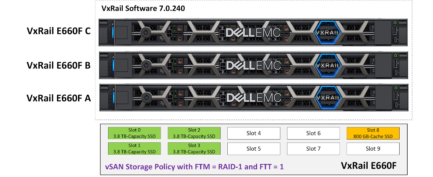
Figure 5.3 – VxRail All-Flash cluster with three nodes
In this scenario, we will add two new VxRail E660F nodes to the VxRail cluster. You can change the FTM settings at any time if the storage resources can fulfill the requirement of your new FTM settings. This operation does not interrupt the operation of the VMs in the VxRail cluster; this is one of the key features of the VxRail system.
In Figure 5.4, the total resources of this VxRail cluster will be increased automatically after adding the new nodes (VxRail E660F D/E) to the existing VxRail cluster, including CPU, memory, and storage resources. The vSAN storage policy with FTM set to RAID-1 and FTT set to 1 is still valid in this VxRail cluster. When the cluster expansion is successfully completed, then you can change the FTM to RAID-5:
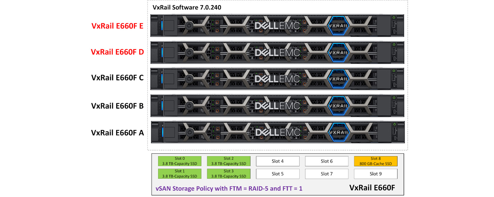
Figure 5.4 – VxRail All-Flash cluster with five nodes
You can see from the examples in Figure 5.2 and Figure 5.4 that the VxRail scale-out operation is very simple and flexible. The following sections will discuss the disk group design of each VxRail model.
Design of disk groups on VxRail E-Series
The cache and capacity disks are predefined in specific disk slots before the VxRail system is delivered to the customer from the Dell factory. The disk slot locations for cache and capacity are fixed when they are made in the Dell factory, and you cannot change them. Figure 5.5 shows the front view of VxRail E660, E660F, and E660N. There are 10 disk slots on these 3 types of VxRail E-Series; disk slots 0 to 7 are used for the capacity tier and disk slots 8 to 9 are used for the cache tier. The capacity disks support SAS/SATA/SSD, and the cache disks support SSD and NVMe SSD:
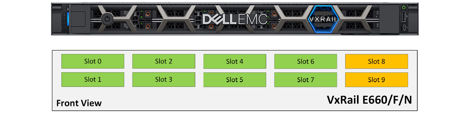
Figure 5.5 – Front view of VxRail E660/F/N
If you scale up the VxRail cluster, you need to consider the following VxRail scale-up rules:
- Mixing the SAS/SATA/NVMe SSDs in the same disk group is not supported.
- Mixing the capacity HDDs with capacity SSDs in the same disk group is not supported.
- All the capacity disks must be of the same capacity in the same disk group.
- Having different capacity disk sizes and types in the different disk groups in a VxRail node is supported.
- Having different cache disk sizes and types in the different disk groups in a VxRail node is supported.
- In VxRail software 7.0.200 or later, a large-capacity disk can be used when replacing a disk in the disk group.
- In VxRail software 7.0.200 or later, a large-capacity disk can be used when expanding a disk group.
In the release of VxRail 7.0.201 and later, VxRail E-Series supports two options of disk groups:
- Option 1: VxRail E-Series supports two vSAN disk groups, which contain one cache disk and up to four capacity disks per disk group. Table 5.1 shows a two-disk-groups configuration for each disk slot in VxRail E660/F/N:
Disk Groups
Cache Tier
Capacity Tier
Disk Group 1
Slot 8
Slot 0
Slot 1
Slot 2
Slot 3
Disk Group 2
Slot 9
Slot 4
Slot 5
Slot 6
Slot 7
Table 5.1 – Two disk groups configuration in VxRail E660/F/N
- Option 2: VxRail E-Series supports one vSAN disk group that contains one cache disk and up to seven capacity disks. Table 5.2 shows a one disk group configuration for each disk slot in VxRail E660/F/N:
Disk Groups
Cache Tier
Capacity Tier
Disk Group 1
Slot 8
Slot 0
Slot 1
Slot 2
Slot 3
Slot 4
Slot 5
Slot 6
Table 5.2 – One disk group configuration in VxRail E660/F/N
If you choose the one disk group configuration in VxRail E-Series, two disk slots (slot 7 and slot 9) are useless (refer to the details in Figure 5.6):
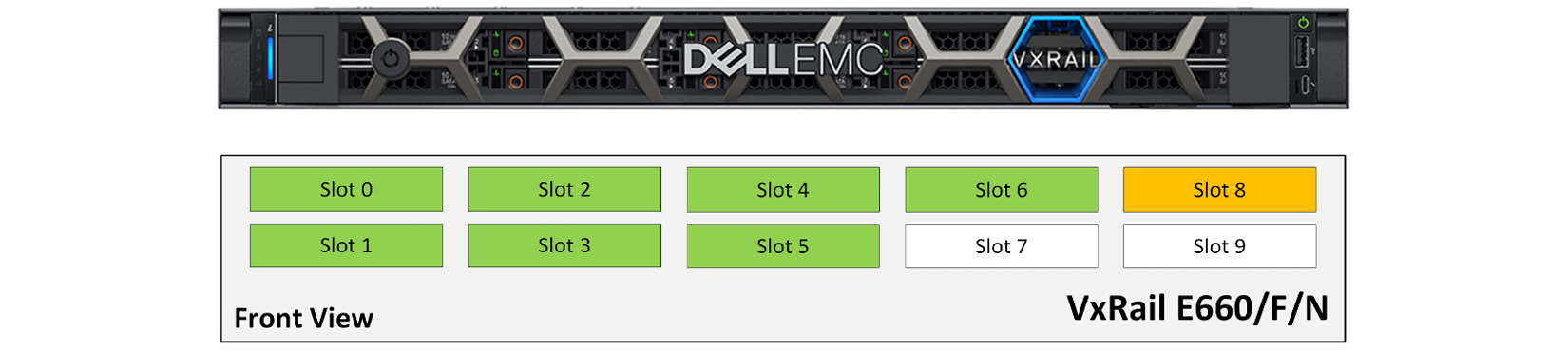
Figure 5.6 – Disk layout for one disk group configuration in VxRail E660/F/N
In VxRail E660 and E660F, you can choose SAS, SATA, or SSD for the capacity tier. For the cache tier, you can choose SSD only. VxRail E660N only supports capacity NVMe for the capacity tier and cache NVMe for the cache tier. Dell’s 15th-generation PowerEdge server has new models of VxRail E-Series: E665, E665F, and E665N. The disk group configuration of E665N is the same as the E660N. The disk group configuration of E665 and E665F is different from E660 and E660F because there are only eight disk slots in VxRail E665 and E665F. Both models also support two disk groups, each disk group with one cache disk and up to three capacity disks (refer to Figure 5.7):
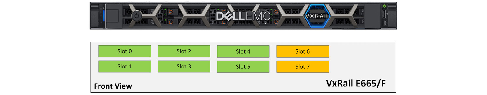
Figure 5.7 – Front view of VxRail E665/F
Table 5.3 shows the two disk groups configuration for each disk slot in VxRail E665/F:
|
Disk Groups |
Cache Tier |
Capacity Tier |
|
Disk Group 1 |
Slot 6 |
Slot 0 |
|
Slot 1 | ||
|
Slot 2 | ||
|
Disk Group 2 |
Slot 7 |
Slot 3 |
|
Slot 4 | ||
|
Slot 5 |
Table 5.3 – Two disk groups configuration in VxRail E665/F
The next section will discuss an unsupported scale-up scenario on VxRail E-Series.
An unsupported scenario of scale-up on VxRail E-Series
In Figure 5.8, there is a VxRail All-Flash cluster with three nodes (VxRail E660F A/B/C). Each node has four 3.8 TB-capacity SSDs and one 800 GB-cache SSD installed. Now, we plan to add two 3.8 TB-capacity SSDs (slots 4 and 5) to expand the disk group in each VxRail E660F node, but this is not a supported scale-up configuration. Because the number of capacity disks supported is up to four, if you want to expand the disk group on each VxRail E660F node, you can create a new disk group in each node:

Figure 5.8 – Unsupported disk group configuration in VxRail E660F
The next section will discuss a supported scenario of scale-up on VxRail E-Series.
A supported scenario of scale-up on VxRail E-Series
Figure 5.9 shows a supported disk group configuration on VxRail E-Series. Each node has eight 3.8 TB-capacity SSDs and two 800 GB-cache SSDs installed. There are two disk groups installed; each disk group contains four 3.8 TB-capacity SSDs and one 800 GB-cache SSD. The new disk group is created by slots 4 to 7 and 9; this is a supported scenario:
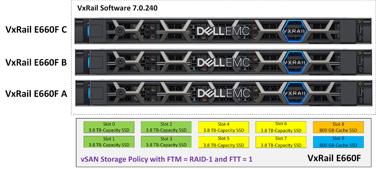
Figure 5.9 – Supported disk group configuration in VxRail E660F
According to Table 5.3, you learned about the disk group design for VxRail E-Series. The next section will discuss the disk group design for VxRail P-Series.
Design of disk groups on VxRail P-Series
Figure 5.10 shows the front view of VxRail P670F. There are 28 disk slots; disk slots 0 to 19 and slots 24 to 27 are used for the capacity tiers, and disk slots 20 to 23 are used for the cache tier. The capacity disks support SAS/SSD, and the cache disks support SSD and NVMe SSD:
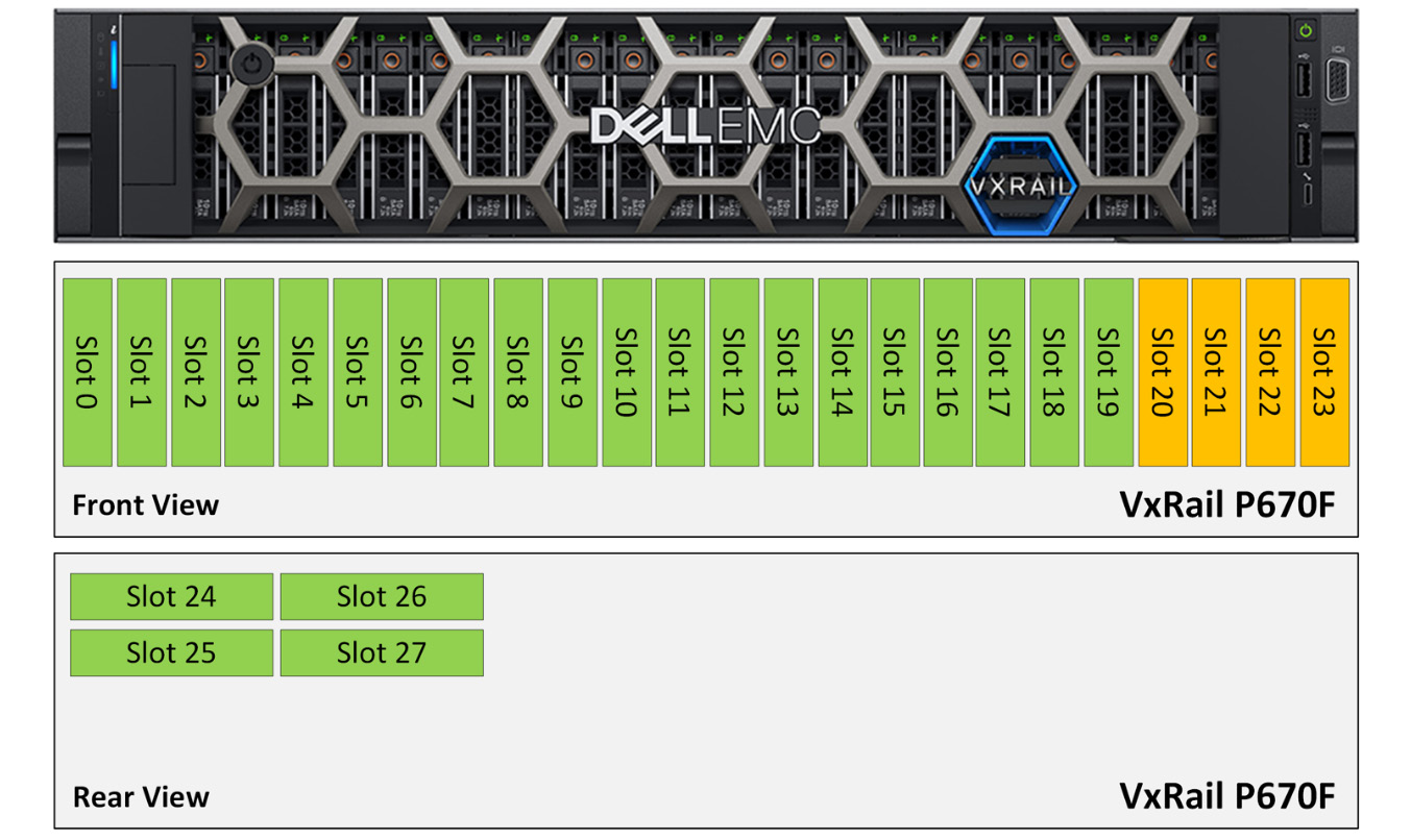
Figure 5.10 – Front view and rear view of VxRail P670F
Important Note
In Dell’s 15th-generation PowerEdge server, only three models of the All-Flash node exist in the VxRail P-Series; they are VxRail P670F, P675F, and P675N.
In the release of VxRail 7.0.201 and later, VxRail P670F supports two options of disk groups:
- Option 1: The first configuration is of four vSAN disk groups, which contain one cache disk and up to five capacity disks per disk group. Table 5.4 shows a four-disk-groups configuration for each disk slot in VxRail E660/F/N:
Disk Groups
Cache Tier
Capacity Tier
Disk Group 1
Slot 20
Slots 0 to 4
Disk Group 2
Slot 21
Slots 5 to 9
Disk Group 3
Slot 22
Slots 10 to 14
Disk Group 4
Slot 23
Slots 15 to 19
Table 5.4 – The first option of disk group configuration in VxRail P670F
- Option 2: The second configuration is of four disk groups, which contain one cache disk and up to six capacity disks per disk group. Table 5.5 shows a four-disk-groups configuration for each disk slot in VxRail E660/F/N:
Disk Groups
Cache Tier
Capacity Tier
Disk Group 1
Slot 20
Slots 0 to 4 and Slot 24
Disk Group 2
Slot 21
Slots 5 to 9 and Slot 25
Disk Group 3
Slot 22
Slots 10 to 14 and Slot 26
Disk Group 4
Slot 23
Slots 15 to 19 and Slot 27
Table 5.5 – The second option of disk groups configuration in VxRail P670F
In Dell’s 15th-generation PowerEdge server, there are two new models of VxRail P-Series: P675F and P675N. In Figure 5.11, the total number of disk slots of P675F/N is less than P670F, with only 24 disk slots. This model can support up to four disk groups:
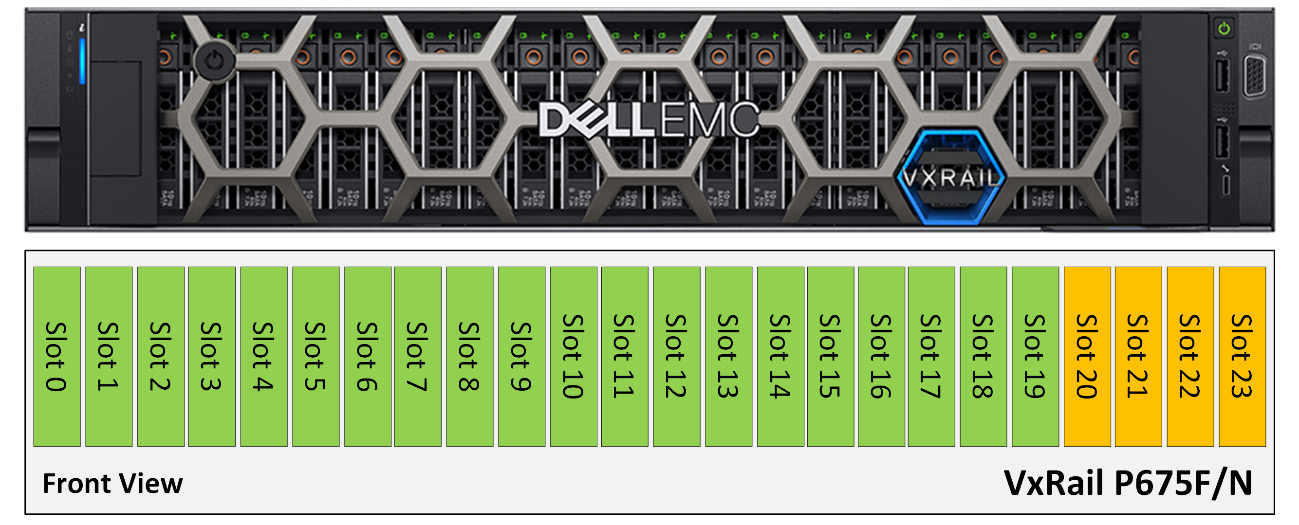
Figure 5.11 – Front view and rear view of VxRail P675F/N
Table 5.6 shows a four-disk-groups configuration for each disk slot in VxRail P675F/N:
|
Disk Groups |
Cache Tier |
Capacity Tier |
|
Disk Group 1 |
Slot 20 |
Slots 0 to 4 |
|
Disk Group 2 |
Slot 21 |
Slots 5 to 9 |
|
Disk Group 3 |
Slot 22 |
Slots 10 to 14 |
|
Disk Group 4 |
Slot 23 |
Slots 15 to 19 |
Table 5.6 – Four disk groups configuration in VxRail P675F/N
The next section will discuss an unsupported scale-up scenario on VxRail P-Series.
An unsupported scenario of scale-up on VxRail P-Series
In Figure 5.12, there is a VxRail All-Flash cluster with three nodes (VxRail P670F A/B/C). There are 28 disk slots on each VxRail P670F node, configured in three disk groups. Each disk group includes one cache SSD and five capacity disks; disk slots 0 to 19 and slots 24 to 27 are used for the capacity tiers, and disk slots 20 to 23 are used for the cache tier. Now, you plan to add one capacity disk to expand each disk group; the new capacity disks are installed on slots 15, 16, and 17. But it is an unsupported disk group configuration; disk slots 15 to 19 are used for the capacity tier of the fourth disk group. You need to install the new capacity into disk slots 24 to 26:
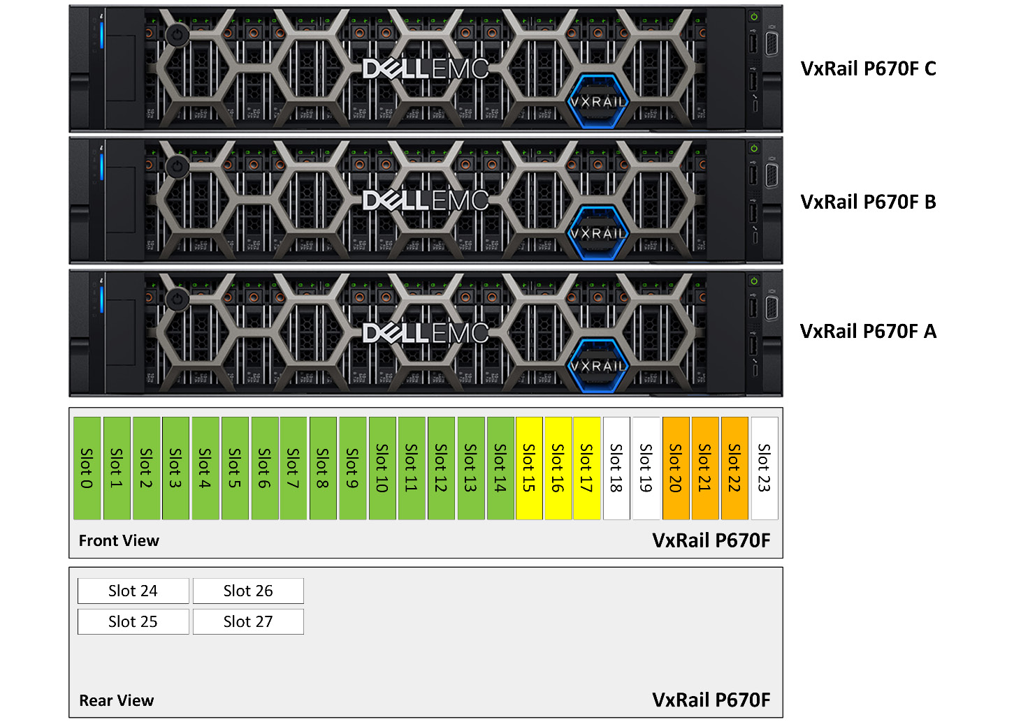
Figure 5.12 – Unsupported disk group configuration in VxRail P670F
The next section will discuss a supported scenario of scale-up on VxRail P-Series.
A supported scenario of scale-up on VxRail P-Series
Figure 5.13 shows a supported disk group configuration on VxRail P-Series. Each node has twenty capacity SSDs and four cache SSDs installed. There are four disk groups installed: each disk group contains five capacity SSDs and one cache SSD. The new disk group is created by slots 15 to 19 and 23; this is a supported scenario:

Figure 5.13 – Supported disk group configuration in VxRail P670F
According to Tables 5.4 and 5.5, you now know the disk group design for all VxRail P-Series systems. The next section will discuss the disk group design for VxRail V-Series.
Design of disk groups on VxRail V-Series
Figure 5.14 shows the front view of VxRail V670F. There are 24 disk slots on VxRail V670F; disk slots 0 to 19 are used for the capacity tiers, and disk slots 20 to 23 are used for the cache tier. The capacity disks support SAS/SATA/SSD, and the cache disks support SSD and NVMe SSD:

Figure 5.14 – Front view of VxRail V670F
In the release of VxRail 7.0.201 and later, VxRail V670F supports two options of disk groups:
- Option 1: Four vSAN disk groups, which contain one cache disk and up to five capacity disks per disk group. Table 5.7 shows a four-disk-group configuration for each disk slot in VxRail V670F:
Disk Groups
Cache Tier
Capacity Tier
Disk Group 1
Slot 20
Slots 0 to 4
Disk Group 2
Slot 21
Slots 5 to 9
Disk Group 3
Slot 22
Slots 10 to 14
Disk Group 4
Slot 23
Slots 15 to 19
Table 5.7 – The first option of disk groups configuration in VxRail V670F
- Option 2: In Figure 5.15, the three vSAN disk groups contain one cache disk and up to five capacity disks per disk group:

Figure 5.15 – The second option of disk groups configuration in VxRail V670F
Table 5.8 shows a three-disk-groups configuration for each disk slot in VxRail V670F:
|
Disk Groups |
Cache Tier |
Capacity Tier |
|
Disk Group 1 |
Slot 21 |
Slots 0 to 6 |
|
Disk Group 2 |
Slot 22 |
Slots 7 to 13 |
|
Disk Group 3 |
Slot 23 |
Slots 14 to 20 |
Table 5.8 – Three disk groups configuration for each disk slot in VxRail V670F
The next section will discuss an unsupported scale-up scenario on VxRail V-Series.
An unsupported scenario of scale-up on VxRail V-Series
In Figure 5.16, there is a VxRail All-Flash cluster with three nodes (VxRail V670F A/B/C). There are 24 disk slots on each VxRail V670F and configured in 1 disk group, which includes 1 cache SSD and 5 capacity SSDs; disk slots 0 to 19 and slots 24 to 27 are used for the capacity tiers, and disk slots 20 to 23 are used for the cache tier. Now, you plan to add two capacity SAS disks to expand this disk group; the new capacity disks are installed on slots 5 and 6. But it is an unsupported disk group configuration, because the type of existing capacity disk is SDD, and the type of the new disk is SAS. The disk type of capacity disks must be the same:
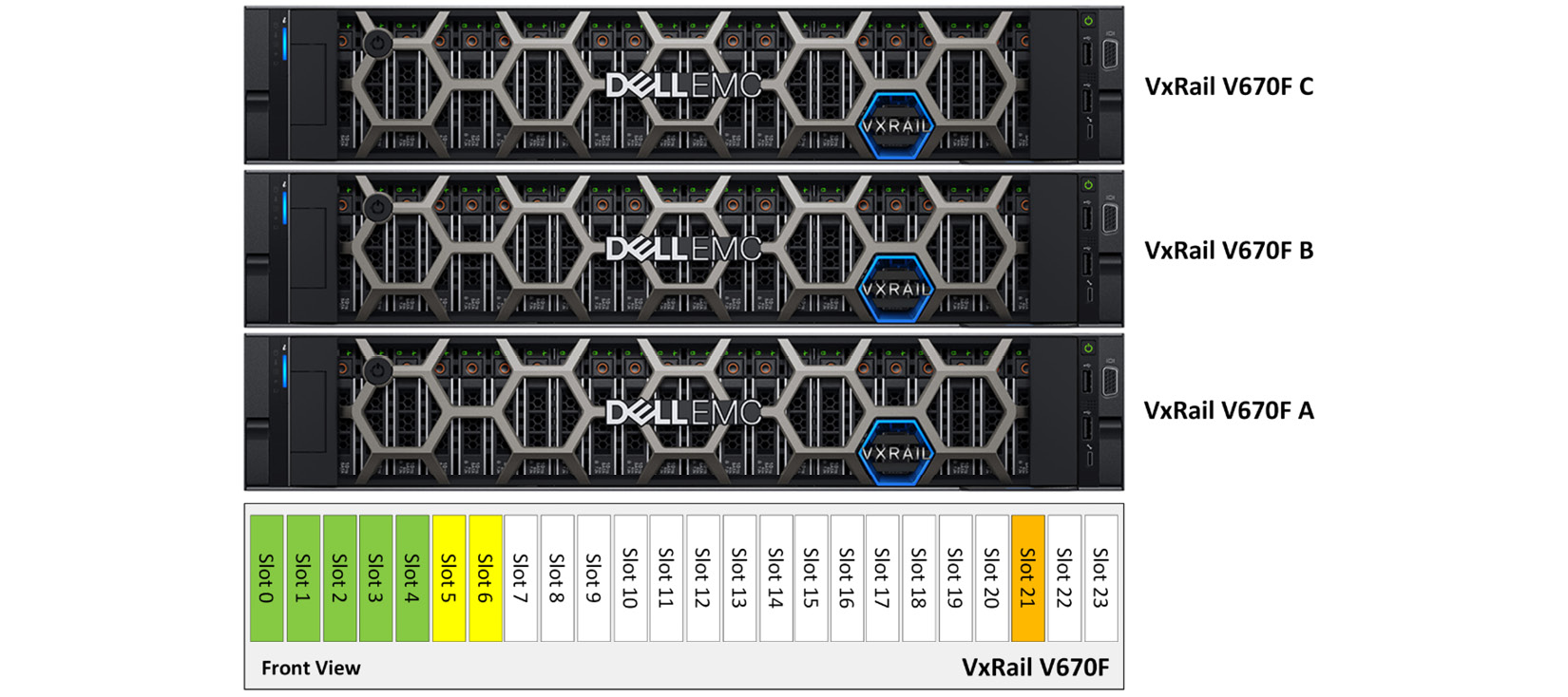
Figure 5.16 – Unsupported disk group configuration in VxRail V670F
The next section will discuss a supported scenario of scale-up on VxRail V-Series.
A supported scenario of scale-up on VxRail V-Series
Figure 5.17 shows a supported disk group configuration on VxRail V-Series. Each node has 10 capacity SSDs and 2 cache SSDs installed. There are two disk groups installed; each disk group contains five capacity SSDs and one cache SSD. The new disk group is created by slots 7 to 11 and 22; this is a supported scenario:
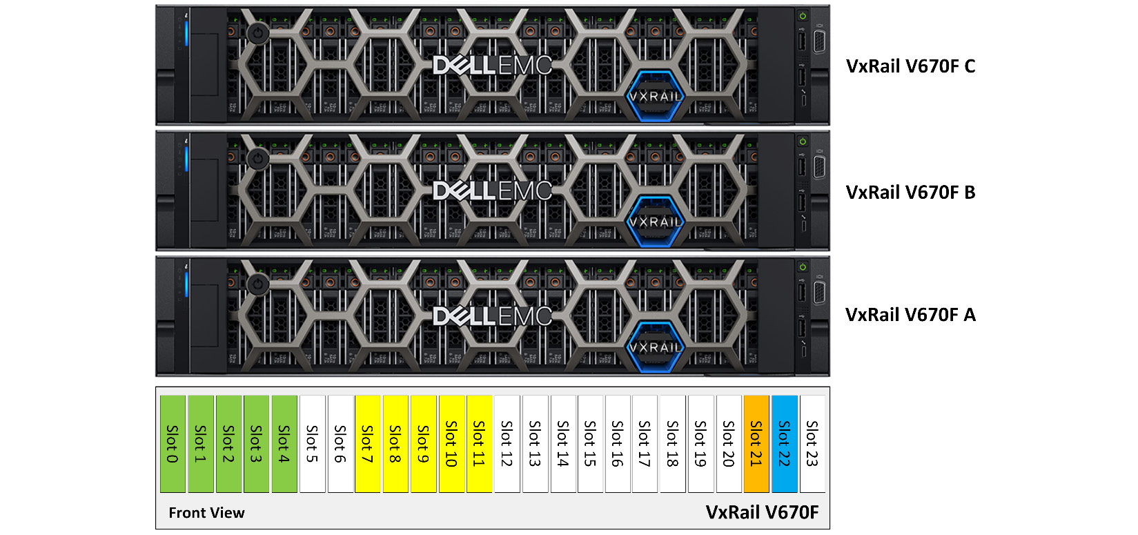
Figure 5.17 – Supported disk group configuration in VxRail V670F
According to Tables 5.7 and 5.8, you now know the disk group design for VxRail V-Series. The next section will discuss the disk group design for VxRail S-Series.
Design of disk groups on VxRail S-Series
This section will discuss the disk group design for VxRail V-Series. Figure 5.18 shows the front view of VxRail S670. There are 16 disk slots on VxRail S670; disk slots 0 to 11 (front view) are used for the capacity tiers, and disk slots 0 to 3 (rear view) are used for the cache tier. VxRail S-Series only supports a hybrid configuration. The capacity disks only support 3.5” SAS/SATA, and the cache disks only support 2.5” SSD or NVMe:
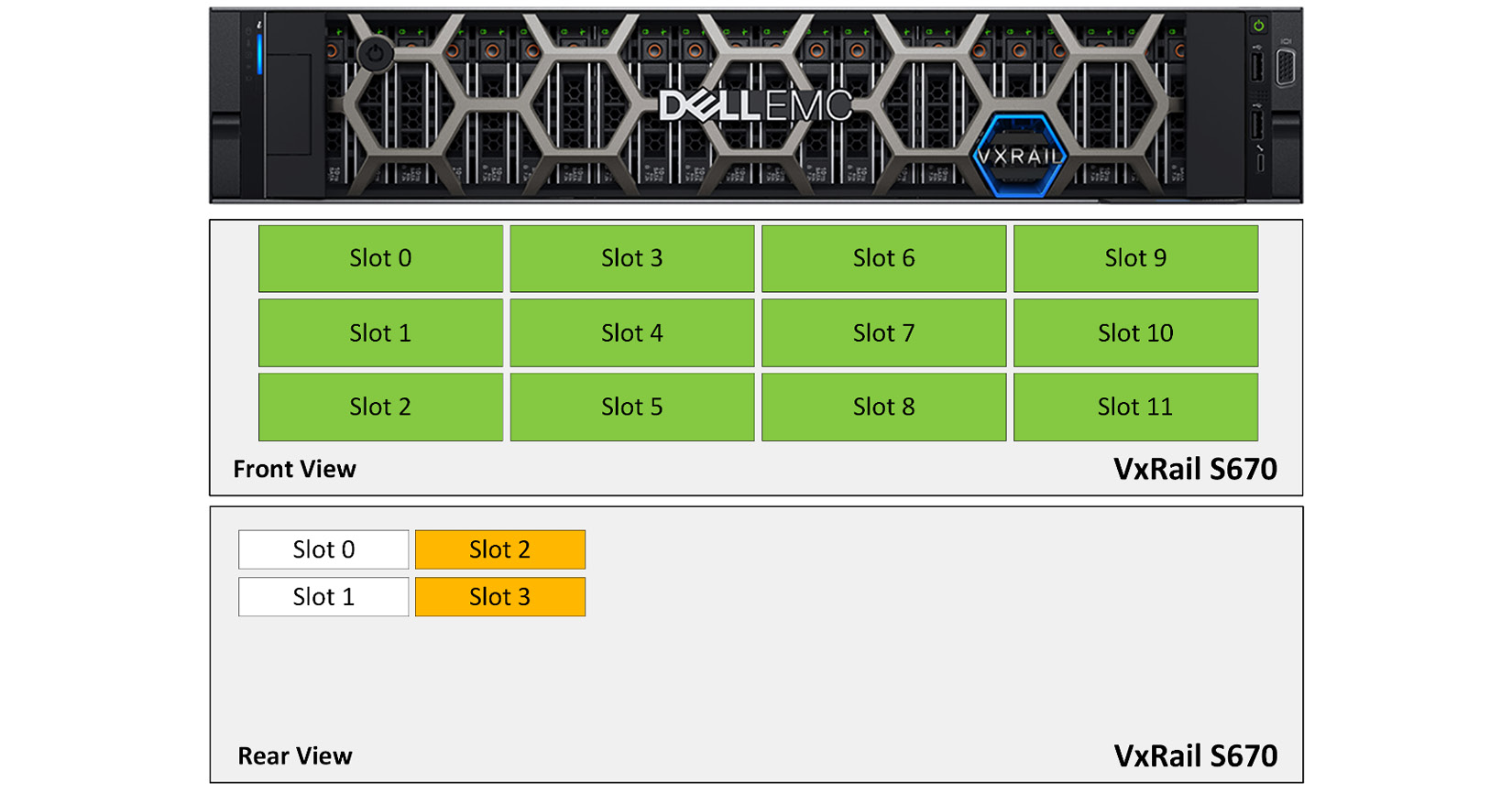
Figure 5.18 – The first option of disk groups configuration in VxRail S670
In the release of VxRail 7.0.201 and later, VxRail S670 supports two options of disk groups:
- Option 1: The two vSAN disk groups, which contain one cache disk and up to six capacity disks per disk group. Table 5.9 shows a four-disk-groups configuration for each disk slot in VxRail S670:
Disk Groups
Cache Tier
Capacity Tier
Disk Group 1
Slot 2 (rear view)
Slots 0 to 5 (front view)
Disk Group 2
Slot 3 (rear view)
Slots 6 to 11 (front view)
Table 5.9 – The first option of disk groups configuration in VxRail S670
- Option 2: Figure 5.19 shows the four vSAN disk groups, which contain one cache disk and up to three capacity disks per disk group:
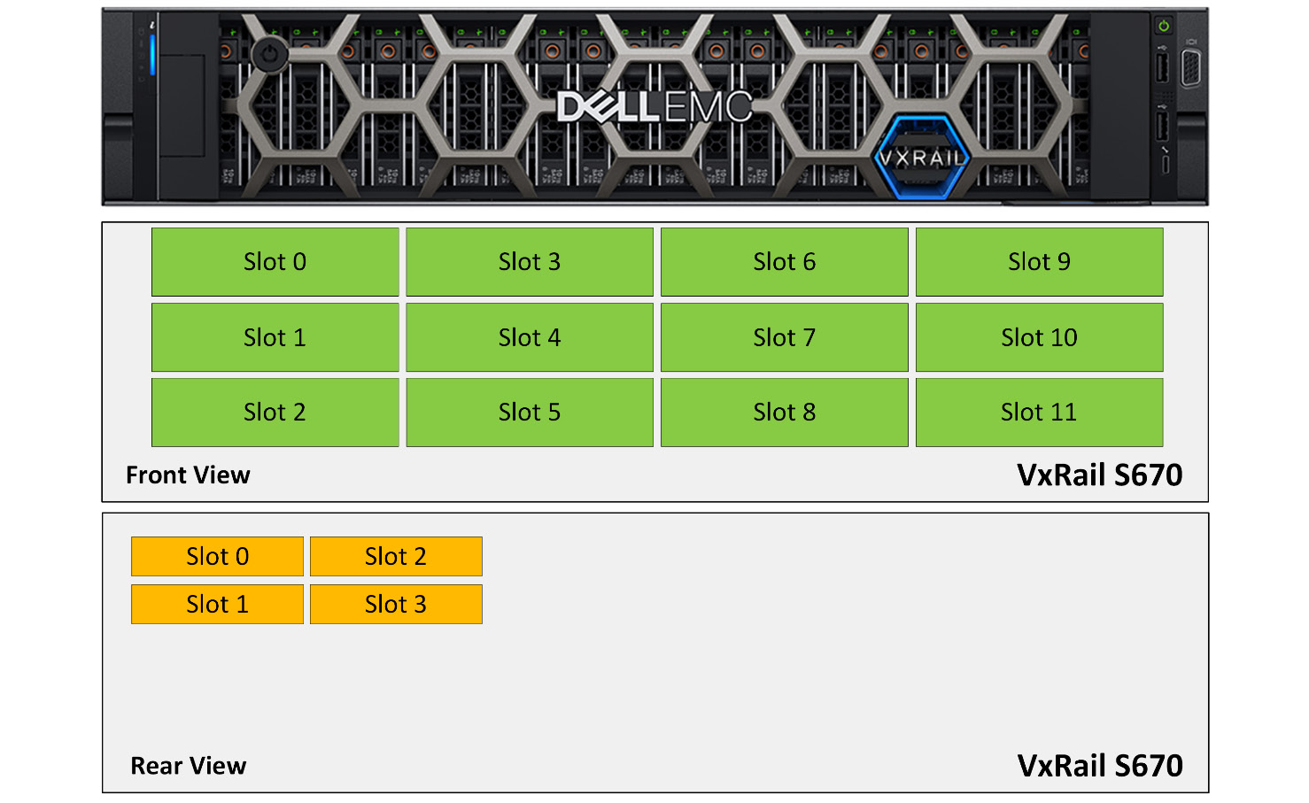
Figure 5.19 – The second option of disk groups configuration in VxRail S670
Table 5.10 shows a four-disk-groups configuration for each disk slot in VxRail S670:
|
Disk Groups |
Cache Tier |
Capacity Tier |
|
Disk Group 1 |
Slot 0 (rear view) |
Slot 0 (front view) Slot 1 (front view) Slot 2 (front view) |
|
Disk Group 2 |
Slot 1 (rear view) |
Slot 3 (front view) Slot 4 (front view) Slot 5 (front view) |
|
Disk Group 3 |
Slot 2 (rear view) |
Slot 6 (front view) Slot 7 (front view) Slot 8 (front view) |
|
Disk Group 4 |
Slot 3 (rear view) |
Slot 9 (front view) Slot 10 (front view) Slot 11 (front view) |
Table 5.10 – The second option of disk groups configuration in VxRail S670
The next section will discuss an unsupported scale-up scenario on VxRail S-Series.
An unsupported scenario of scale-up on VxRail S-Series
In Figure 5.20, there is a VxRail hybrid cluster with three nodes (VxRail S670 A/B/C). There are 16 disk slots on each VxRail S670 and configured in one disk group, which includes one cache SSD (rear view, slot 3) and three capacity HDDs (front view, slots 0 to 2); disk slots 0 to 11 (front view) are used for the capacity tiers, and disk slots 0 to 3 (rear view) are used for the cache tier. Now, you plan to create a new disk group on each node, which includes six capacity HDDs (front view, slots 3 to 8) and one cache SSD (rear view, slot 2). But it is an unsupported disk group configuration because the new disk group only supports up to three capacity HDDs:
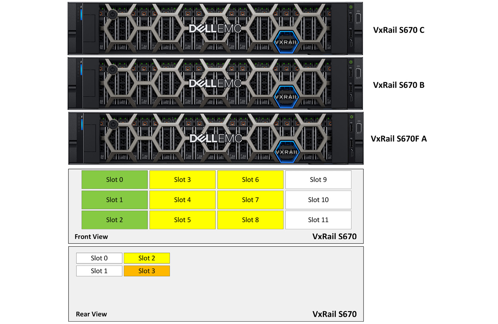
Figure 5.20 – Unsupported disk group configuration in VxRail S670
The next section will discuss a supported scenario of scale-up on VxRail S-Series.
A supported scenario of scale-up on VxRail S-Series
Figure 5.21 shows a supported disk group configuration on VxRail S-Series. Each node has six capacity disks and two cache SSDs installed. There are two disk groups installed; each disk group contains three capacity SSDs and one cache SSD. The new disk group is created by slots 3 to 5 (front view) and slot 1 (rear view); this is a supported scenario:

Figure 5.21 – Supported disk group configuration in VxRail S670
According to Tables 5.9 and 5.10, you learned about the disk group design for VxRail S-Series. The next section will discuss the disk group design for VxRail D-Series.
Design of disk groups on VxRail D-Series
Figure 5.22 shows the front view of VxRail D560/F. There are only eight disk slots on VxRail D560/F; disk slots 0 to 5 are used for the capacity tiers, and disk slots 6 to 7 are used for the cache tier. The capacity disks support SAS/SSD, and the cache disks support SSD:

Figure 5.22 – Front view of VxRail D560/F
In the release of VxRail 7.0.201 or later, VxRail D560/F only supports one option of a disk group, which contains one cache disk and up to three capacity disks per disk group. Table 5.11 shows a disk group configuration for each disk slot in VxRail D560/F:
|
Disk Groups |
Cache Tier |
Capacity Tier |
|
Disk Group 1 |
Slot 6 |
Slot 0 |
|
Slot 1 | ||
|
Slot 2 | ||
|
Disk Group 2 |
Slot 7 |
Slot 3 |
|
Slot 4 | ||
|
Slot 5 |
Table 5.11 – Two disk groups configuration in VxRail D560/F
The next section will discuss an unsupported scale-up scenario on VxRail D-Series.
An unsupported scenario of scale-up on VxRail D-Series
In Figure 5.23, there is a VxRail hybrid cluster with three nodes (VxRail D560 A/B/C). There are eight disk slots on each VxRail D560F node and configured in one disk group, which includes one cache SSD (slot 7) and three capacity SSDs (slots 0 to 2); disk slots 0 to 5 are used for the capacity tiers, and disk slots 6 to 7 are used for the cache tier. Now, you plan to add one cache SSD to slot 6, but it is an unsupported disk group configuration because slot 6 is used for cache SSD for the second disk group on D560F:
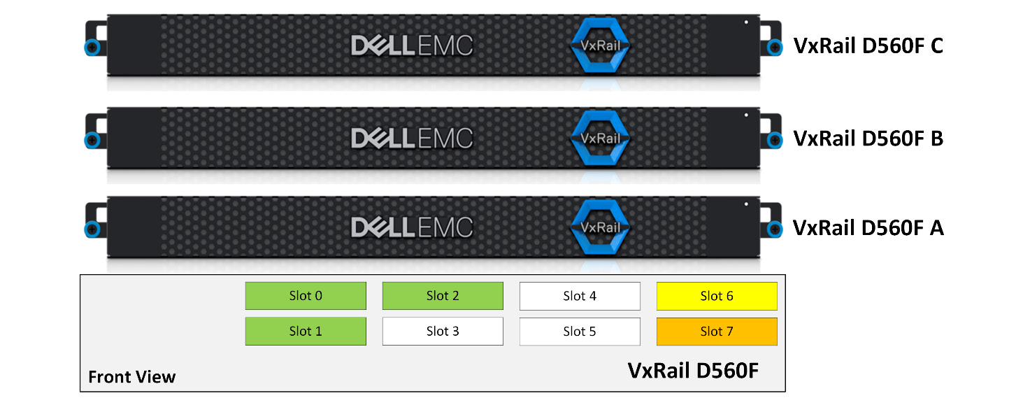
Figure 5.23 – Unsupported disk group configuration in VxRail D560F
The next section will discuss a supported scenario of scale-up on VxRail D-Series.
A supported scenario of scale-up on VxRail D-Series
Figure 5.24 shows a supported disk group configuration on VxRail D-Series. Each node has six capacity disks and two cache SSDs installed. There are two disk groups installed; each disk group contains three capacity SSDs and one cache SSD. The new disk group is created by slots 3 to 5 and slot 7; this is a supported scenario:

Figure 5.24 – Supported disk group configuration in VxRail D560F
According to Table 5.11, you know the disk group design for VxRail D-Series. The next section will discuss the disk group design for VxRail G-Series.
Design of disk groups on VxRail G-Series
This last section will discuss the disk group design for VxRail G-Series. Figure 5.25 shows the front view and rear view of VxRail G560/F. There are 24 disk slots on the VxRail G-Series chassis; disk slots 1 to 5, 7 to 11, 13 to 17, and 19 to 23 are used for the capacity tiers, and disk slots 0, 6, 12, and 18 are used for the cache tier. It supports the installation of four nodes into each VxRail G-Series chassis. VxRail G-Series supports hybrid and All-Flash configurations. The capacity disks only support 3.5” SAS/SATA, and the cache disks only support 2.5” SSD or NVMe:

Figure 5.25 – Front view and rear view of VxRail G560/F
In the release of VxRail 7.0.201 or later, VxRail G560/F only supports one disk group.
Each disk group contains one cache disk and up to five capacity disks per disk group. Table 5.12 shows a disk group configuration for each disk slot in the VxRail G-Series chassis:
|
G-Series Chassis |
Node ID |
Disk Groups |
Cache Tier |
Capacity Tier |
|
Node 1 |
Disk Group 1 |
Slot 0 |
Slots 1 to 5 | |
|
Node 2 |
Disk Group 1 |
Slot 6 |
Slots 7 to 11 | |
|
Node 3 |
Disk Group 1 |
Slot 12 |
Slots 13 to 17 | |
|
Node 4 |
Disk Group 1 |
Slot 18 |
Slots 19 to 23 |
Table 5.12 – Disk groups configuration in VxRail G560/F
Important Note
All VxRail G-Series nodes in a chassis must be identical configurations.
The next section will discuss an unsupported scale-up scenario on VxRail G-Series.
An unsupported scenario of scale-up on VxRail G-Series
In Figure 5.26, there is a VxRail hybrid cluster with four nodes (VxRail G560 A/B/C/D). There are six disk slots on each VxRail D560 node and these are configured in one disk group, which includes one cache SSD and three capacity disks; disk slots 1 to 5, 7 to 11, 13 to 17, and 19 to 23 are used for the capacity tiers, and disk slots 0, 6, 12, and 18 are used for the cache tier in the G-Series chassis. Now, you plan to add two capacity SSDs to each G560 node (slots 4, 5, 10, 11, 16, 17, 22, and 23, but it is an unsupported disk group configuration. Because this VxRail cluster is a hybrid configuration, it is not supported to change to an All-Flash configuration:
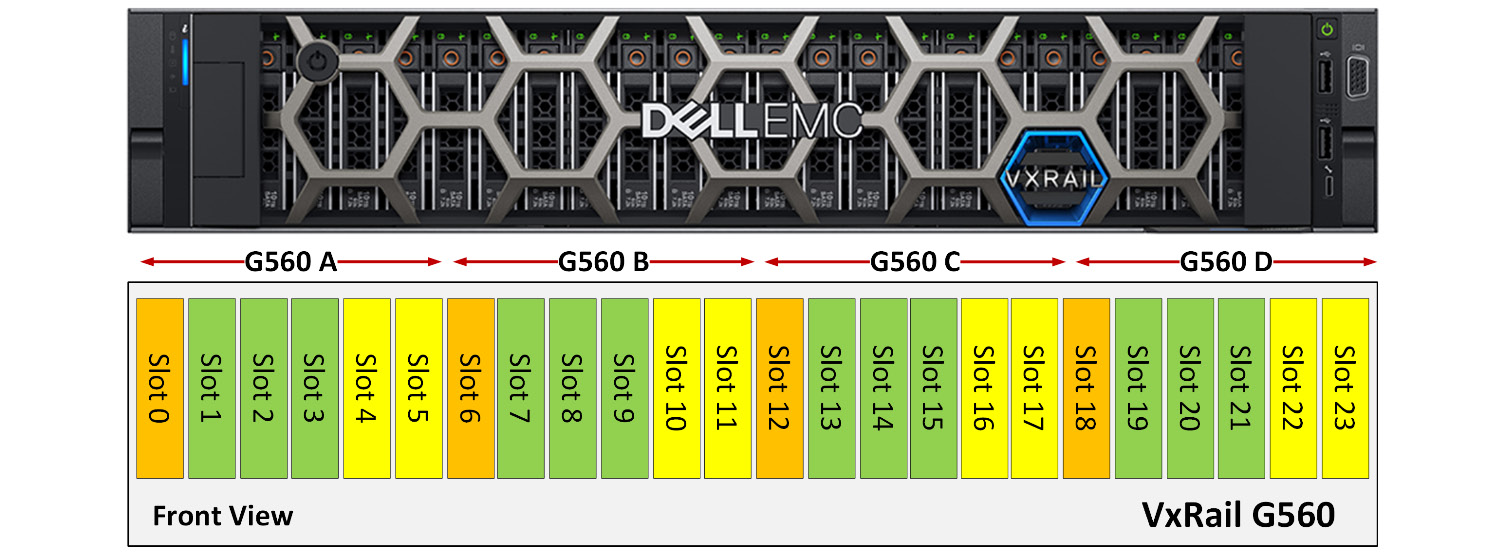
Figure 5.26 – Unsupported disk group configuration in VxRail G560
The next section will discuss a supported scenario of scale-up on VxRail G-Series.
A supported scenario of scale-up on VxRail G-Series
Figure 5.27 shows a supported disk group configuration on VxRail G-Series. Each node has six capacity disks and one cache SSDs installed. There is one disk group installed. The new capacity disks are created in each node in slots 5, 11, 17, and 23; this is a supported scenario:
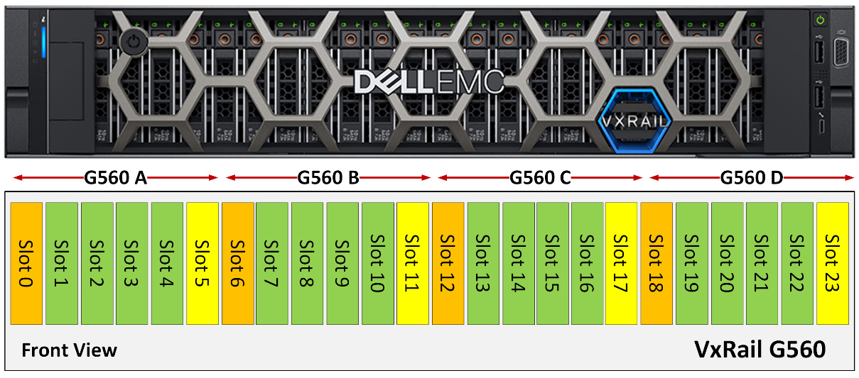
Figure 5.27 – Supported disk group configuration in VxRail G560
According to Table 5.12, you know the disk group design for VxRail G-Series.
Lastly, Table 5.13 shows a summary of disk group configurations for each VxRail series:
|
VxRail Model |
Cluster Type |
Model |
Form Factor |
Number of Supported Disk Groups per Node |
|
E-Series |
Hybrid, All-Flash |
E660, E660F, E660N E665, E665F, E665N |
1 unit |
2 |
|
P-Series |
All-Flash |
P670F P675F, P675N P580N |
2 units |
4 |
|
V-Series |
All-Flash |
V670F |
2 units |
4 |
|
S-Series |
Hybrid |
S670 |
2 units |
4 |
|
D-Series |
Hybrid, All-Flash |
D560, D560F |
1 unit |
2 |
|
G-Series |
Hybrid, All-Flash |
G560, G560F |
2 units per chassis |
1 |
Table 5.13 – Summary of disk group configurations for each VxRail series
Summary
In this chapter, you covered an overview and learned about the design of cluster expansion in the VxRail 7.x system, including the scale-out and scale-in rules for each model for a VxRail node. Compared to the traditional architecture of server and storage, you can see that VxRail cluster expansion is very easy and flexible.
In the next chapter, you will learn about the design of the vSAN two-node cluster on VxRail and the best practices of this solution.
Questions
The following are a short list of review questions to help reinforce your learning and help you identify areas which require some improvement.
- Which two types of rules can be supported on the VxRail 7.x system?
- VxRail upgrade rules
- VxRail update rules
- VxRail scale-up rules
- VxRail expansion rules
- VxRail scale-out rules
- None of these
- Which of the following is the wrong description of VxRail scale-out rules?
- All-Flash and NVMe nodes cannot be mixed in a VxRail Hybrid cluster.
- The mixing of All-Flash nodes and NVMe nodes in the same cluster is not supported.
- Neither 10 GB nor 25 GB networks can be used for vSAN traffic.
- Only a 1 GB network can be used for a VxRail hybrid cluster with a single processor.
- The maximum number of VxRail nodes per cluster is 64.
- What is the maximum number of disk groups that can be supported on the VxRail E660F?
- One disk group
- Two disk groups
- Three disk groups
- Four disk groups
- Five disk groups
- Six disk groups
- What is the maximum number of disk groups that can be supported on the VxRail P670F?
- One disk group
- Two disk groups
- Three disk groups
- Four disk groups
- Five disk groups
- Six disk groups
- What is the maximum number of disk groups that can be supported on the VxRail V670F?
- One disk group
- Two disk groups
- Three disk groups
- Four disk groups
- Five disk groups
- Six disk groups
- What is the maximum number of disk groups that can be supported on the VxRail S670?
- One disk group
- Two disk groups
- Three disk groups
- Four disk groups
- Five disk groups
- Six disk groups
- What is the maximum number of disk groups that can be supported on the VxRail D560F?
- One disk group
- Two disk groups
- Three disk groups
- Four disk groups
- Five disk groups
- Six disk groups
- What is the maximum number of disk groups that can be supported on the VxRail G560F?
- One disk group
- Two disk groups
- Three disk groups
- Four disk groups
- Five disk groups
- Six disk groups
- Which VxRail model of the capacity disk can be supported for up to seven disks?
- VxRail E660
- VxRail V670F
- VxRail P670F
- VxRail S670
- VxRail G560F
- None of these
- Which VxRail model only supports a hybrid configuration?
- VxRail E-Series
- VxRail P-Series
- VxRail V-Series
- VxRail S-Series
- VxRail D-Series
- VxRail G-Series
- Which VxRail models support both hybrid and All-Flash configurations?
- VxRail E-Series
- VxRail P-Series
- VxRail V-Series
- VxRail S-Series
- VxRail D-Series
- VxRail G-Series
- In Figure 5.28, the disk slot configuration belongs to which VxRail model?
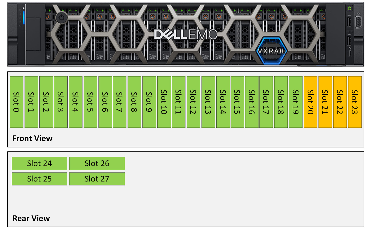
Figure 5.28 – Disk slot configuration of the VxRail 7.x system
- VxRail E-Series
- VxRail P-Series
- VxRail V-Series
- VxRail S-Series
- VxRail D-Series
- VxRail G-Series