Creating a High-Level Framework for FijiNet
In this section, we create a high-level framework for our ISP customer FijiNet. Combining requirements, assumptions, and evaluations formulated in Chapter 2 with the architectural model and principles developed in Chapter 3, we apply preferred practices for creating a logical design.
For descriptions of services and other elements of a high-level framework, refer to the previous section “Creating a High-Level Framework” on page 66.
The following information focuses on decisions we made to create a logical design for FijiNet, a small ISP entering the market. Where applicable, we explain the reasons for decisions and describe trade-offs.
We create a logical design for FijiNet by performing the following:
“Identify High-Level Topology for FijiNet” on page 107
“Identify Services Within the FijiNet Topology” on page 110
“Define Service Flows for FijiNet” on page 113
“Define Networking Components for FijiNet” on page 121
Identify High-Level Topology for FijiNet
Based upon FijiNet’s requirements, we identified the high-level topology shown in FIGURE 4-18.
Figure 4-18. FijiNet Topology

POP is the access point where subscribers connect to FijiNet. Access to the POP is through a NAS with high-density terminations and digital modems.
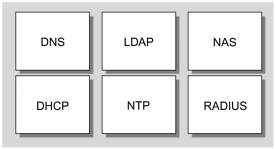
Infrastructure services running at the POP to facilitate connectivity for subscribers are DNS, DHCP, LDAP, RADIUS, and NTP.
Basic services are email, web hosting, Internet news, and FTP. FijiNet is not offering any value-added services for the initial deployment.
For email service, both POPv3 and IMAP4 provide access, and SMTP provides mail delivery. Static web hosting is provided by Apache web server (part of Solaris 8 Operating Environment). Internet news is outsourced to a UseNet provider.
FijiNet POP Topology
The POP topology for most ISPs is consistent and does not vary greatly. As shown in FIGURE 4-19, FijiNet’s POP topology is identical to the generic POP.
Figure 4-19. FijiNet POP Topology
Because FijiNet is a single-site configuration, content resides locally at the data center; therefore, a cache server is unnecessary.
FijiNet Internal Infrastructure Network Topology
In contrast to the generic logical network topology shown in FIGURE 4-3 on page 69, we partioned FijiNet’s network infrastructure into three layers: internal network, external network, and management network, as shown in FIGURE 4-20. We chose this approach because of FijiNet’s size, limited requirements, and cost constraints.
Figure 4-20. FijiNet Logical Network Topology

FijiNet’s network topology is a 3-tier architecture model:
The external network is for external services, and it closely matches the DMZ network.
The internal network is for internal services, and it consolidates the services, application, and content networks.
The management network for FijiNet is in-band (due to cost restrictions), compared to our generic model earlier, which is out-of-band. The management network for FijiNet is for systems, network, and security management.
FijiNet can add other tiers in the future to achieve an N-tier model, as their subscriber population increases or when their architecture requires modification to support new services.
Ideally, we would like to configure the internal and external networks on the same switch and the management network on a separate switch, so that it is out-of-band. However, due to FijiNet’s cost constraints, we use a single-switch configuration. Consequently, we configure the management network in-band.
We use two T1s for Internet connectivity, and two CT3s for dial-up access. In the next chapter, we show how to calculate, for capacity planning, the number of modems and high-speed trunks needed for this configuration.
Identify Services Within the FijiNet Topology
Based on our 3-tier architectural model for FijiNet, we identify services within each network layer: internal, external, and management.
To meet FijiNet’s requirements, we made the following changes from our generic model, presented earlier in this chapter:
Email, web, and news services normally configured at the services network are on the internal network.
The FTP server normally configured on the DMZ network is on the internal network.
The NTP, external secondary DNS, RADIUS, mail relay, and NAS are on the external network.
Network, security, systems management, log, backup, and console servers are on the management network.
FijiNet External Network
FIGURE 4-21 shows the services we place on FijiNet’s external network.
Figure 4-21. FijiNet External Network
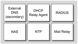
The external network is for external services, such as infrastructure services that are required for POP. External name resolution and time synchronization require direct Internet access.
For security reasons, we place the DHCP server on the internal network. A DHCP relay agent relays DHCP messages to the DHCP server.
Our goal is to place as many services on the internal network as possible, unless they are absolutely required to reside on the external network.
FijiNet Internal Network
FIGURE 4-22 shows the services we place on FijiNet’s internal network.
Figure 4-22. FijiNet Internal Network
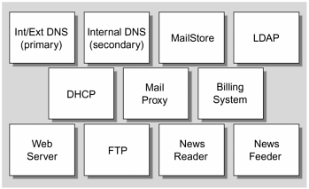
Because we are using a modular approach with a single-server configuration, we place all basic services on a single server, which resides on the internal network.
We acknowledge that there are many design trade-offs in a single-server approach at each layer. Also, there are risks. All risks must be identified and mitigated. In the next chapter, we address the risks and how to mitigate them.
FijiNet Management Network
Services typically running on the management network are console server, log server, boot/install server, and management (system, network, security) server.
Because of cost constraints and initial subscriber population size, we place the backup server on the management network rather than having a separate network for it.
FIGURE 4-23 shows the services we place on FijiNet’s management network.
Figure 4-23. FijiNet Management Network

Define Service Flows for FijiNet
In Chapter 3, we applied architectural principles and a model to FijiNet’s requirements. Here, we apply the principles and model to FijiNet’s service flows to achieve an optimal design.
FijiNet DNS
As FIGURE 4-24 shows, we use a split-DNS configuration (internal and external) for FijiNet.
Figure 4-24. FijiNet DNS

The external secondary DNS server is on the external network, and the primary DNS server is on the internal network. The primary DNS server functions as the primary for both internal and external domains.
The external secondary DNS server communicates with DNS servers on the Internet for name resolution of hosts on the Internet. It periodically receives zone transfers from the primary DNS server on the internal network for zone data updates.
FijiNet LDAP
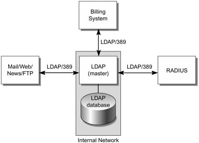
We place an LDAP server on the internal network, as shown in FIGURE 4-25. Because of cost constraints, we omit replica servers.
Figure 4-25. FijiNet LDAP
Note
We plan on using an iPlanet directory server, so we can configure multiple master directory servers.
FijiNet DHCP
FIGURE 4-26 shows the flow of the DHCP service.
Figure 4-26. FijiNet DHCP Server

When users dial up, the NAS contacts the DHCP relay agent for dynamic configuration information. The DHCP relay agent relays DHCP messages to the DHCP server, which returns the information to users.
The DHCP relay agent is an intermediary between the DHCP server and users. The DHCP relay agent can be configured on a dedicated server or on a router.
For FijiNet, we decided that the best configuration was to enable the DHCP relay agent on the router. This configuration has two advantages. First, a DHCP server does not have to reside on the external network. By having the DHCP server on the internal network, we reduce security risk. Second, with DHCP relay agents enabled at the router, this allows the DHCP server to scale well, so that we do not need a DHCP server at each network because BOOTP/DHCP packets cannot be forwarded beyond the local network.
FijiNet RADIUS
FIGURE 4-27 shows the flow of the RADIUS service.
Figure 4-27. FijiNet RADIUS

All remote access from users is authenticated by the RADIUS server, which interfaces with the LDAP server.
To maintain a centralized authentication method, we decided not to use a local RADIUS database and/or external relational database. RADIUS queries the LDAP server for user information to authenticate users.
FijiNet NTP
FIGURE 4-28 shows the flow of the NTP service.
Figure 4-28. FijiNet NTP

For FijiNet, the NTP server synchronizes with external NTP servers’ clocks on the Internet. It’s not economical to maintain an external clock for a small ISP.
NTP servers frequently multicast to NTP clients to check the time. If a clock is not synchronized, NTP clients synchronize to the NTP server clock time.
The NTP server frequently multicasts to public Internet NTP servers, synchronizing with them if time drift is detected.
Refer to the following web site for a list of public NTP servers:
http://www.eecis.udel.edu/∼mills/ntp/servers.html
FijiNet Email Service
FIGURE 4-29 shows the flow of Email service.
Figure 4-29. FijiNet Email Service
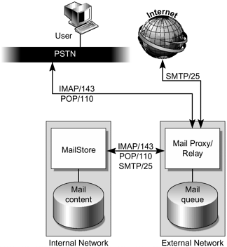
On the external network, a mail relay and mail proxy are configured. The mail relay is the intermediary that relays mail messages in and out of FijiNet. The mail proxy is configured for users to access and retrieve email, using POP and IMAP.
For the mail relay, there is dedicated disk space for incoming and outgoing mail queue. The mail relay does not contain mail messages. On the internal network, a MailStore contains all mail messages.
Users must not be able to connect to the MailStore directly from the Internet. Both POP3 and IMAP4 are available for retrieving mail at the front end.
FijiNet Web Service
FIGURE 4-30 shows the flow of web service.
Figure 4-30. FijiNet Web Service

To access web pages, subscribers connect to a web server via browsers. The web server is on the internal network. Static web content resides on the same system as the web server. Due to cost constraints, there is not a centralized NFS server for content. Because there is no dynamic content, an application server is unnecessary.
FijiNet News Service
FIGURE 4-31 shows the flow of news service.
Figure 4-31. FijiNet News Service

Both news reader and news feeder are on the same physical server on the internal network. Users can read and post articles to the news reader. There is a single feed from the UseNet provider to FijiNet. There is not a downstream feed to any other news server.
For FijiNet, we could place the news reader/feeder on either the external or internal network. Because of the single-server configuration, which limits the flexibility of service decomposition, we place the news reader/feeder on the internal network. All news articles, spools, and histories are stored locally. An NFS server is not used as a centralized news content server.
Define Networking Components for FijiNet
After identifying topology, services within the topology, and service flows, we determine networking components for FijiNet that best fit the services and overall logical design.
Routers and Switches
For FijiNet’s 10,000-subscriber environment, we determine that an L3 router with two WAN interfaces is needed for Internet connectivity, and at least one 10/100 Mbit/sec port is needed for internal connectivity.
For scalability, we suggest that two 10/100 Mbps are required if additional routers are added to provide availability. In Chapter 5, we provide information for capacity planning of WAN/LAN ports for routers.
We determine that an L2 switch with a sufficient number of 10/100 Mbit/sec ports is needed. To ensure that the ports can scale to support up to 100,000 users, we must design the architecture so that FijiNet can add ports on demand for additional network devices and servers. Because of their cost constraints, we start with a minimum configuration. FijiNet can then scale horizontally when needed. The aggregation of port density can be done by cascading or daisy chaining multiple switches. In Chapter 5, we provide information for capacity planning the ports on switches.
Load Balancers
Due to cost constraints, we accept that load balancers are not applicable to FijiNet’s market-entry architecture of 10,000 subscribers. However, when FijiNet grows to 100,000 subscribers or higher and load distribution becomes critical to service availability, load balancers will be necessary. Therefore, it is important to plan for future traffic growth and how load balancing fits into the overall architecture, such as scalability, availability, performance, etc. described in the architectural model in Chapter 3.
Intrusion Detection System (IDS)
Because FijiNet’s service offering is for residential users and no SLAs are being offered, an IDS is not required.
An IDS is not cost effective for a 10,000-subscriber environment. However, as FijiNet grows and adds different types of users (such as business subscribers) and services, security will become critical. When a higher level of security is required, an IDS will be important to protect unauthorized access to services and data.
