
Failure modes in structural applications of fiber-reinforced polymer (FRP) composites and their prevention
Abstract:
Fiber-reinforced polymer (FRP) composite materials have been increasingly used in civil engineering applications in the past two decades. Their wide ranging use, however, is still not realized due to a few fundamental issues including high material costs, relatively short history of applications and the gaps in the development of established standards. Design safety requires that all possible modes and mechanisms of failure are identified, characterized, and accounted for in the design procedures. This chapter provides a review of the failure types encountered in structural engineering applications of FRP and the preventive methods and strategies that have been developed to eliminate or delay such failures. As part of preventive measures, various non-destructive testing (NDT) and structural health monitoring (SHM) methods used for monitoring FRP applications are discussed with illustrative examples.
fiber-reinforced polymer (FRP)
non-destructive testing (NDT) methods
5.1 Introduction
Fiber-reinforced polymer (FRP) composite materials have been increasingly used in civil engineering applications in the past two decades. This relatively new class of materials, offers several mechanical and durability properties superior to the conventional construction materials, which make them the material of choice in many applications despite their relatively high cost. The structural engineering applications range from all composite structural systems and components to the use of FRP as internal or external reinforcement in conventional structures for improved durability and structural performance. Already accounting for the second largest share in FRP composites shipments in North America, the construction market is likely to take the lead as the use of FRPs in structural engineering applications becomes mainstream.
Failure, although an undesired phenomenon, is at the root of structural engineering design. In an effort to design against failures, engineers learn from failures encountered in controlled or in-service environments. Design safety requires that all possible modes and mechanisms of failure are identified, characterized, and accounted for in the design procedures included in standards. As promising as FRPs are for use in structural engineering applications, characterization of the respective failure modes and development of preventive measures is a prerequisite for the development of comprehensive standards that will enable their widespread use.
This chapter provides a review of the failure types encountered in structural engineering applications of FRP and the preventive methods and strategies that have been developed to eliminate or delay such failures. The scope is mostly limited to failure of FRP strengthened concrete and steel structures which represent the most common applications of FRP in structural engineering. As part of preventive measures, various non-destructive testing (NDT) and structural health monitoring (SHM) methods used for monitoring FRP applications are discussed with illustrative examples.
5.2 Failures in structural engineering applications of fiber-reinforced polymer (FRP) composites
FRP materials may exhibit quite sophisticated failure modes based on their highly diverse composition, structure, and geometry. Characterization of failure modes and development of associated failure criteria for various FRP materials is an active field of research around the world (Hinton et al,. 2004; Davila et al,. 2005; Knops, 2010). The composition and structure of FRP composites are very briefly reviewed below as a basis for the following discussions on their material and failure behavior.
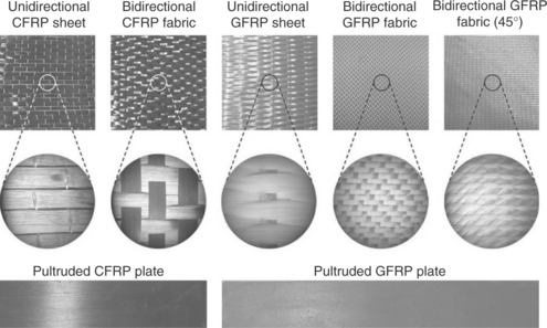
The basic composition of FRP composites is formed by high strength and stiffness fibers embedded in a polymer matrix with distinct interfaces between them (Hull and Clyne, 1996; Peters, 1997; Barbero, 2010). In this form, both fibers and matrix retain their physical and chemical identities, yet they produce a combination of properties that cannot be achieved with either of the constituents alone. The fibers serve as the principal load-carrying members. The surrounding matrix keeps the fibers in a desired location and orientation, acts as a load transfer medium between them, and protects them from environmental effects. FRP composites can be produced in various types depending on the volume fraction, length, orientation, and type of fibers in the polymer matrix. A laminate is the most common form of composites for structural applications, fabricated by stacking a number of thin layers of unidirectional laminae. Maximum strength and stiffness properties are achieved in the fiber axis direction when all the fibers are unidirectional. This arrangement is highly anisotropic and is suited for applications where the laminate will be subjected to tension in the fiber direction only. To obtain more isotropic properties, alternate layers of fibers may vary between 0 and 90°, resulting in less directionality, but at the expense of decreased properties in the absolute fiber direction. Alternatively, woven fabrics can be used with various weave patterns based on the specific application. Biaxially woven fabrics provide good strength in the fiber directions and allow fast composites application through wet layup. However, they are generally less effective in strength compared to laminates due to their three-dimensional structure. Figure 5.1 shows various types of commercially available carbon FRP (CFRP) and glass FRP (GFRP) composite systems used in structural strengthening applications (Gunes, 2004).
Failure behavior of a unidirectional FRP laminate under loading in different directions provides an informative illustration of the complex failure modes in FRP composite materials in general. Figure 5.2(a) shows the stress–strain behavior of unidirectional carbon and glass FRP plates and sheets in comparison with that of reinforcing steel. As can be seen from the figure, a linearly elastic stress–strain behavior followed by an undesirably brittle failure is common to all presented types. Figure 5.3(b) conceptually illustrates the variation in the failure behavior of unidirectional FRP composites as the direction of the loading changes (Peters, 1997). The strength properties, shown in normalized form with respect to the tensile strength, rapidly deteriorate as the loading deviates from the fiber axis and reach very low values for angles more than 20°. The failure modes are fiber rupture and buckling in tension and compression, respectively, for loading close to the fiber axis, shear failure for intermediate angles, and transverse tensile and compressive failures for large deviations from the fiber axis. Analysis of deformation and failure for multi-directional laminates requires use of more involved analysis methods and associated failure criteria (Hull and Clyne, 1996; Peters, 1997; Ochoa and Reddy, 2010).
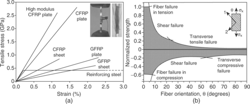
5.2 Tensile stress–strain diagrams of selected unidirectional FRP systems (a) and conceptual failure behavior at different angles to fiber axis (b).
Despite several favorable characteristics of FRP composites, their brittle failure behavior described in Fig. 5.2 is a major concern for structural engineers. Ductility, defined – at different scales – as the ability to undergo inelastic deformation before failure, is a very important safeguard against failures in structural engineering. Ductility not only results in warning before ultimate failure, but also reduces the dynamic load demand through increased energy dissipation and damage. A measure of ductility is the ratio of inelastic and elastic deformation called the ductility ratio (μ). For structural and reinforcing steel, the ductility ratio is typically greater than one hundred (μs > 100) and concrete has a much lower ductility ratio of around two (μc ≈ 2). At the structural level, a ductility ratio (calculated by the ratio of inelastic and elastic drift) μΔ = 4–6 is generally needed for satisfactory structural performance. Hence, a fundamental concern regarding use of FRPs in structural applications is their ductility ratio of μ ≈ 1, even more brittle than concrete, which at first sight does not promise a favorable contribution to the system ductility. A partially compensating property of FRP composites is their typically much higher ultimate strain (εuf ≈ 0.012–0.023) compared to that of concrete (εuc ≈ 0.003) and the yield strain of reinforcing steel (εys ≈ 0.002) (Fig. 5.2(a)). Since the ductility of reinforcing steel in a properly designed reinforced concrete (RC) member is never fully realized due to concrete failure in compression, the additional FRP reinforcement, if properly designed and installed, acts as additional reinforcement that contributes to the load capacity and/or ductility depending on the application (Gunes et al,. 2013a,b). As proper design requires a thorough knowledge of the failure modes and mechanisms, comprehensive experimental and modeling research is needed for general and application-specific failure types of structural systems that include FRP composites as a basis for development of associated design codes.
5.2.1 Failures in compression members
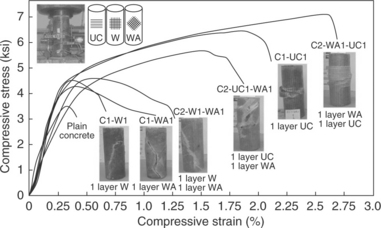
Use of FRP composites for additional reinforcement and/or confinement in compression members has been a very effective and cost-efficient type of composites application in structural engineering. Its application is much easier and faster than the alternative conventional methods such as rein-forced concrete or steel jacketing of columns. In confinement strengthening, FRP composite plate or fabrics are wrapped or fiber strands are wound in the shear reinforcement direction to enhance shear strength and confinement. The wrapped or wound FRP reinforcement confines the concrete to improve the concrete compressive strength as well as the ductility, resulting in improvement of performance in compression. The lateral confining pressure depends on the thickness and orientation of the FRP reinforcement and the corresponding failure stress. Figure 5.3 shows the stress–stain behavior and failure of six axially loaded concrete cylinders wrapped with one or two layers of GFRP sheets with three different fiber orientations (Au and Büyüköztürk, 2005). All FRP-wrapped cylinders displayed an improvement in both load capacity and ductility compared to the plain concrete cylinder. The degree of improvement and the failure mode were affected by the number of layers, fiber orientation, and the stack sequence. Similar improvements were obtained in lateral load and deformation capacity of FRP-wrapped columns (Colomb et al,. 2008).
The success of column strengthening using FRPs stems from the ability to form closed hoops with multiple layers of FRP reinforcement which provides effective confinement for concrete. The confinement is most effective for circular columns and reduces for rectangular columns, especially for high aspect ratios of the column cross-section (Maalej et al,. 2003). Promising results obtained from numerous experimental studies have resulted in several FRP-confined concrete models for use in design practice (Bisby et al,. 2005). Although there is little agreement between the developed models, their characteristic contribution to the structural performance is very similar and their use in design generally does not make a significant difference in terms of the structural performance evaluation of the retrofitted system (Gunes et al,. 2013a,b).
5.2.2 Failures in tension members
In structural engineering applications, tension is most generally resisted by steel and there are several issues regarding the use of FRPs in conjunction with steel without concrete as a load transfer medium. In a strengthening application, the strengthening material is generally expected to have a similar or higher stiffness compared to the base material of the member being strengthened. In this respect, FRP composites have been a viable choice of materials for use in conjunction with wood, masonry, concrete, and even aluminum (in aviation and aerospace industries) as the typical elastic modulus of FRPs is higher than those of these materials (Triantafillou, 1998). Structural steel, however, has an elastic modulus higher than most commercially available FRP composites used in structural strengthening applications (Fig. 5.2(a)). Hence, as far as elastic deformations are concerned, use of FRPs for strengthening of steel structures does not make much sense from both mechanics and economy perspectives since more FRP reinforcement would be needed than, for instance, additional steel reinforcement to perform the strengthening. Nevertheless, FRP reinforcement for steel becomes effective in the inelastic deformation stage during which steel yields under constant stress while FRPs continue their linearly elastic deformation behavior until failure (Fig. 5.2(a)). Hence, FRP composites are more suitable for improving the ultimate load capacity of steel structures than improving their serviceability. Additional issues include high interfacial stresses in FRP-bonded steel members and potential durability concerns such as galvanic corrosion of the steel substrate in contact with CFRP which is a conductive material. Despite the concerns, FRP strengthening of steel structures has received significant research attention in recent years due to the potential of eliminating welding and bolting in steel members, and ease of installation (Büyüköztürk et al,. 2004; Zhao and Zhang, 2007). Continued research in this area focusing on the interface stresses and durability problems together with the recent advances in nano-fiber and nanotube composites (Coleman, et al,. 2006) are likely to boost FRP applications to steel structures.
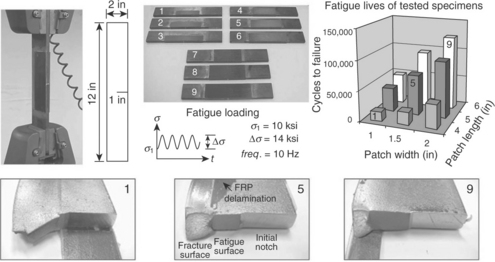
Repair of fatigue-damaged steel members using FRP composites is a specific type of application that is both mechanically and economically well justified. Fatigue cracks can develop in tension members or in the tension regions of flexural members under repeated loading. Repair of a fatigue-damaged member aims at restoring or improving the fatigue resistance of the member and increasing its remaining service life. Commonly used repair techniques involve drilling a hole at the crack tip to eliminate stress con-centrations and to control crack growth, or welding and/or bolting of a steel angle or plate over the cracked area. The problems associated with such repairs is that they may inflict further damage to the structure in terms of reducing its load carrying capacity due to drilling of holes, or may introduce further local stress concentrations which can promote further fatigue cracking. Due to the uncertainties in the reliability of repaired members, replacement is generally the preferred action unless replacement cost is very high. Conceptually, composite patches reinforced with high modulus fibers can be expected to restrain opening deformations of cracks occurring in steel components to which the patches are bonded. Thus, the bonded patch reduces the stress intensity factor at the crack tip through bridging the stresses between the cracked plate and composite patch. It reduces the stress field in the vicinity of the crack leading to retardation of crack growth and an improvement in fatigue life.
Figure 5.4 shows the results of an experimental study that involves tension fatigue testing of side-notched steel specimens patched with CFRP laminates having different lengths and widths (Gunes, 2004). As shown in the figure, CFRP patches have resulted insignificant improvements in the fatigue life of the specimens which would have failed right away without the patch due to the high amplitude of cyclic loading. The improvement in fatigue life was dependent on the size of the CFRP patch, which lends itself to modeling of the delayed crack propagation and calculation of the remaining fatigue life after patching. Preliminary environmental exposure studies carried out on similar specimens concluded that environmental exposure had insignificant influence on the effectiveness of the repair and that the CFRP patch had prevented rather than accelerated the corrosion of the steel substrate. Continued studies using coupled environmental exposure and fatigue loading should provide more reliable information regarding the potential durability problems in FRP-patched steel members. The method in general was found to be a very effective, cost efficient and easy application of FRP composites to repair fatigue cracks in steel structures in order to prolong their service life considerably before replacing the damaged members.
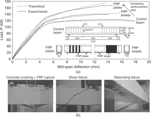
5.2.3 Failures in flexural members
Studies on the use of FRP composites to improve the serviceability and ultimate capacity of flexural members were the earliest FRP applications in structural engineering due to the debonding and durability problems encountered with conventional methods such as strengthening using bonded steel plates. Early experimental studies have shown the high potential and characteristic contribution of FRP reinforcement to the flexural and shear capacity of flexural members and have identified the possible failure modes (Büyüköztürk and Hearing, 1998). Despite the proven potential of the method, FRP strengthening of flexural members raised some concerns regarding the effectiveness, safety, and reliability of the method. Figure 5.5(a) shows the flexural capacity increase in reinforced concrete beams upon strengthening with CFRP plates and sheets. Depending on the FRP reinforcement ratio, the flexural capacity of the member can be dramatically increased, but this increase in capacity is accompanied by a reduction in the deformation capacity, hence the ductility of the member which is an undesired behavior. The figure also indicates that wet layup applications of FRP sheets may not be as effective as intended, especially below a certain thickness, due to premature failures caused by possible stress concentrations. Identified failure modes of FRP strengthened RC and steel flexural members can be classified into three groups as flexural, shear, and debonding failure modes as illustrated for RC members in Fig. 5.5(b) (Büyüköztürk et al,. 2004). The flexural and shear failure modes are very similar to those encountered in reinforced concrete flexural members and the analysis of the strengthened member can be performed using the classical ultimate strength design principles with modifications to account for the additional FRP reinforcement. The debonding failure modes, which cannot be characterized by ultimate strength analysis, were of particular concern due to their premature and brittle nature. Hence, if the strengthening design and application is not performed by properly considering all failure modes, the strengthening may not only be ineffective, but also it may harm the originally ductile member by causing its brittle failure. These concerns, which are not valid for FRP applications to columns, require more attention to the failure behavior of FRP-strengthened flexural members.
5.3 Strategies for failure prevention
Engineers learn from failures to prevent them from happening in real-life applications. Structural engineering applications of FRP composites have been researched and applied in pilot and field applications for more than two decades and have produced a fairly large database of failures. Significant progress has been made in characterization and modeling of failure types and development of associated design procedures, but there is still much room for improvement. For certain applications, such as FRP wrapping of columns for improvement of column shear capacity and ductility, the positive contribution of the FRP reinforcement to the application objectives is guaranteed (Fig. 5.3). The potential risk for this application may be that the strengthening may be less effective than intended, or in the worst case scenario, may be ineffective. For other applications, such as FRP strengthening of beams, insufficient consideration to debonding problems may lead to a performance lower than that of the member before strengthening. Figure 5.6 shows an illustrative example of the possible consequences of FRP strengthening of the beam shown in Fig. 5.5, depending on the shear capacity of the beam and the anchorage conditions of the FRP reinforcement. As can be seen from the figure, FRP strengthening can turn a perfectly ductile beam to a brittle one if the shear capacity and anchorage conditions cannot accommodate the increase in flexural capacity. Figure 5.6 shows the evolution of beam behavior with increasing shear capacity, through internal steel or external FRP shear reinforcement and improving anchorage condition. As important as the wide range of ductility behavior is the position of the ACI 440 provision for limiting FRP strain (ACI 440, 2002) shown with a dashed line on the figure. This provision provides the limiting FRP strain that should not be exceeded in design calculations, even if the FRP material can accommodate a higher strain. As can be seen in Fig. 5.6, most failure strains of FRP reinforcement are below the strain limit, which indicates that a design based only on the strain limit could be unconservative by a large margin. Hence, specification of FRP materials in structural engineering applications should note the possible failure modes associated with the specific application and the safety risks involved at the current state of knowledge.
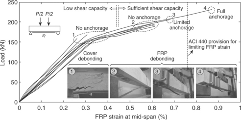
5.6 Failure behavior of FRP-strengthened beams depending on beam shear capacity and bond anchorage conditions.
Before examples of methodologies developed or applied for failure prevention in FRP applications in structural engineering are presented, the framework strategies are described below to set the stage.
5.3.1 Safe-life versus fail-safe approaches
Among various failure prevention approaches, it is of interest to note two distinct generic approaches to dealing with damage in structures, primarily those under dynamic loading, in an effort to prevent failures: the safe-life and fail-safe approaches (Suresh, 1998). In the safe-life approach, the typical service load spectra experienced by the structure under service conditions is determined. Based on this information, the components are analyzed or tested in the laboratory under load conditions that are similar to service spectra, and a useful service life is estimated for the component. The estimated service life, modified by a safety factor, is called the safe life for the component. At the end of the safe operational life, the component is automatically retired from service, even if it has considerable residual service life. The safe-life approach depends on achieving a specified life without the development of damage leading to failure (fatigue crack, delamination, debonding etc.), so the emphasis is on the prevention of damage initiation.
The fail-safe concept, on the other hand, is based on the argument that even if an individual member of a large structure fails, there should be sufficient structural integrity in the remaining parts to enable the structure to operate safely until the damage is detected and repaired. Components that have multiple load paths are generally fail-safe because of structural redundancy. In addition, the structure may contain additional safeguards to prevent undesirable levels of damage occurrence. This approach mandates periodic inspection along with the requirement that the damage detection techniques be capable of identifying flaws to enable prompt repairs or replacements.
Selection between safe-life and fail-safe approaches in maintenance of structures, particularly those under dynamic loading, is a problem of economy versus safety. In civil engineering, the fail-safe approach is generally preferred for economic reasons, although there are exceptions. In Canada, for instance, safe-life techniques have been used for bridges at the expense of higher maintenance costs based on the principle that ‘it is better to replace a number of bridge components a few years too soon rather than have one bridge replaced too late’ (Sweeney, 1990).
The safe-life approach, despite the higher costs involved, is possible for FRP applications in structures under dynamic loading such as bridges. However, for other FRP applications performed to resist design loadings, such as retrofitting a building or even the columns of a bridge against earthquakes, it is difficult, if not impossible, to determine a safe life based on the design event. While it is possible to define a safe life based on durability or cyclic debonding tests or to treat FRP applications as an interim solution during a predefined safe life until a more comprehensive solution is planned and executed, this is usually not even an option due to lack of necessary funds. Hence, the failure prevention practices for FRP applications must be closer to fail-safe approaches that require periodic inspections as part of the failure prevention strategy.
5.3.2 Redundant design against failure
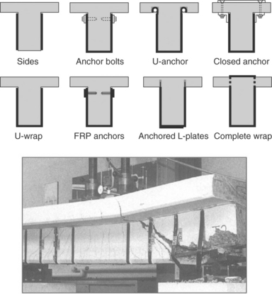
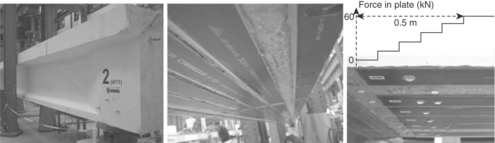
A possible failure prevention strategy for FRP applications in structural engineering is to conservatively provide added redundancy in the design especially for known brittle failure modes even if the design procedure does not call for it. For the debonding failures presented in Fig. 5.6, a debonding model was developed that performed better than the ACI 440 provision for the limiting strain (Gunes et al,. 2009). This study concluded that until a generally applicable model is included in the codes, the FRP flexural reinforcement ends should be anchored along a length equal to the effective depth of the beam as an added precaution against brittle debonding failures. A conservative approach in shear resistance of the beam is also important in preventing brittle failures. If the beam requires shear strengthening, most of the configurations shown in Fig. 5.7 also provide additional bond anchorage for the flexural reinforcement and reduce the probability of debonding failures. For beams with sufficient shear resistance, mechanical anchors at the ends of the bonded FRP flexural reinforcement can also help to prevent brittle debonding failures (Gunes, 2004). An alternative strategy is to use thermal curing to gradually reduce stresses at plate ends to avoid stress concentrations. Such an example is shown in Fig. 5.8 where a full-scale prestressed girder was strengthened by bonding prestressed FRP plates using the gradient method that produced a force gradient in the FRP plate over a length of 0.5 m at the plate ends to gradually reduce the force in the plate to zero (Czaderski and Motavalli, 2007). This type of measure is also possible for FRP applications to steel structures since mechanical anchorage by drilling holes would defeat the purpose of using bonded reinforcement. For such measures, inspection and monitoring practices become more important unless a safe-life approach is taken.
5.3.3 Local versus global monitoring approaches: non-destructive testing (NDT) and structural health monitoring (SHM)
Verifying and monitoring the effectiveness of FRP composites applications in structural engineering is an indispensible means of failure prevention at the current state of knowledge on FRP materials and their interaction with the conventional construction materials. Verification of the effectiveness of FRP strengthening/retrofit applications may be possible in the short term through monitoring the behavior of the structure before and after the application. Figure 5.9 shows such a verification for a bridge on I-65 in Louisville, Kentucky, USA (Harik and Peiris, 2012). Cracks that developed close to the supports of some of the girders in the elevated spans of the bridge were repaired using bonded CFRP sheets. Monitoring of both relative horizontal and vertical movements between the girders and the sup-porting piers was carried out through LVDTs mounted on the girders. The figure. shows the girders as well as the measured relative horizontal movement before and after the retrofit, which clearly verifies the effectiveness of the repair. It should be noted that this verification was a targeted implementation for a specific application at a known location on the structure with known deformations to monitor. Once it is determined that the application works, verifying the long-term effectiveness must be performed either by continued monitoring or through periodic inspections depending on the resources. Inspection of known locations on the bridge can be per-formed using various NDT techniques developed and adapted for civil engineering applications (Büyüköztürk, 1998). Several such techniques were also adapted for inspection and evaluation of FRP applications in civil structures (Dong and Ansari, 2011).
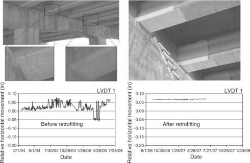
5.9 Short-term monitoring of relative horizontal movement between a girder and the supporting pier of a bridge before and after retrofitting with bonded CFRP sheets for verification of effectiveness. (Courtesy of Prof. Issam Harik, University of Kentucky, USA)
Global monitoring approaches within the area of SHM measure the deformation and vibrations at strategic locations on the structure and attempt to relate any changes in the dynamic characteristics of the structure with damage occurrence. Advanced applications in this area employ system identification routines for localization and sizing of damage (Gunes and Gunes, 2012, 2013). Both NDT and SHM approaches are discussed in greater detail in the next section.
5.4 Non-destructive testing (NDT) and structural health monitoring (SHM) for inspection and monitoring
NDT and SHM are generally associated with local and global inspection and monitoring of structures with certain areas of overlap in between. Another distinction can be that the former is generally focused on physical properties of materials and detection of anomalies, while the latter is generally focused on deformation behavior of structures and components for damage detection. Both approaches and the specific methods included therein have their strengths and limitations with respect to applicability, sensitivity, and accuracy depending on the application. The following sub-sections discuss and provide illustrative examples of SHM and NDT methods that are mostly applied to bonded FRP-strengthened structures.
5.4.1 Stress wave methods
The stress wave or acoustic methods include the traditional sounding tech-niques such as hammer tapping or chain dragging and more advanced methods such as impact-echo (IE), ultrasonic testing (UT), and acoustic emission (AE). In principle, the stress wave methods are based on elastic wave propagation in solids which takes place in forms of compression (P) waves and shear (S) waves in the solid, and surface waves or Rayleigh (R) waves along the surface. Inhomogeneity in the material causes scattering of sound waves which can be recorded and interpreted to extract information about the condition and elastic properties of materials (Blitz and Simpson, 1996; Kundu, 2007). Limitations of these methods include low directivity and resolution at low frequencies and the requirement of intimate contact between the test equipment and the object under test.
Impact-echo involves transmission of a transient pulse into concrete by a mechanical impact, and analysis of the reflected waves recorded at the concrete surface in the frequency domain. Due to its low frequency range, this method is more suitable for rapid preliminary survey of areas for locating the anomalies (Tawhed and Gassman, 2002). Images of these anomalies can then be captured using more comprehensive ultrasonic testing methods. Impact-echo is sometimes used in quality control of bond and detection of bond defects in structural engineering applications of FRP composites.
Acoustic emission is a passive condition monitoring technique which allows continuous testing of a structure rather than at regular intervals (Blitz and Simpson, 1996). Acoustic emission refers to the pulses due to the change in the elastic strain energy, which occurs locally in the material and at material interfaces as a result of deformation, debonding, and fracture. Part of this energy propagates through the material which can be detected by highly sensitive transducers placed on the surface of the structure. AE is generally used for detection and monitoring purposes rather than providing an imaging capability (Grosse and Ohtsu, 2010). This technique was used in monitoring damage build-up and failure of FRP-wrapped compression members in the laboratory (Mirmiran et al,. 1999), quality control of full-scale hybrid FRP-concrete bridge spans in the manufacturing plant prior to construction (Ramirez et al,. 2009), and field monitoring of an FRP strengthened non-prismatic reinforced concrete beam (Carpinteri et al,. 2007). While promising results were reported by these studies, use of this technique for long-term monitoring of FRP applications is hindered by the requirement for continuous field monitoring and the difficulty of differentiating between the stress waves from damage and those due to other factors such as vehicular traffic. Use of this method is likely to increase in the future in parallel with the developments in hybrid and all composite structural members as well as effective signal processing algorithms.
Ultrasonics refers to the study and application of ultrasound which is sound of a pitch too high to be detected by the human ear, i.e. of frequencies greater than about 18 kHz (Blitz and Simpson, 1996; Kundu, 2007). The technique involves transmission of ultrasound waves into the material using a transducer in contact with the surface of the object. The scattered signals are then recorded and interpreted. The data obtained from ultrasonic experiments can be used to reconstruct an image of the inclusions and inhomogeneity in the material using tomographic imaging algorithms. Applications of this technique include thickness determination, measurement of elastic modulus, and detection and imaging of cracks, voids, and delaminations.
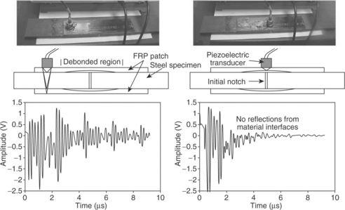
Ultrasonic pulse-echo involves introduction of a stress pulse into the material at an accessible surface by a transmitter. The pulse propagates into the material and is reflected by cracks, voids, delaminations, or material interfaces. The reflected waves, or echoes, are recorded at the surface and the receiver output is either displayed on an oscilloscope or stored for further processing. There are several methods of examining a test specimen using the pulse-echo technique (Cartz, 1995). The A-scan or A-scope method is a 1D view of the defects in the material. Figure 5.10 shows results obtained from ultrasonic A-scans of a partially debonded FRP-patched steel specimen. The response from the debonded region lacks the reflections from substrate material interfaces which is a clear indication of debonding at the FRP–steel interface (Gunes, 2004). The B-scan or B-scope method involves a series of parallel A-scans and produces a 2D view of the defects in the material. The C-scan or C-scope method involves a series of parallel A-scans performed over a surface. For high frequency ultrasound imaging applications which can be used for NDT of steel or FRP composites, display of B- or C-scans can provide significant information about the interior defects due to the high directivity of the waves (Kundu, 2012). For concrete, however, the presence of coarse aggregate, often exceeding 10 mm in diameter, requires that ultrasonic testing be conducted at relatively low frequencies in order to avoid excessive attenuation caused by scattering (Blitz and Simpson, 1996; Büyüköztürk, 1998).Thus, the ultrasonic beam has virtually no directional characteristics, which makes it difficult to infer the size of the defects.
5.4.2 Acoustic-laser technique
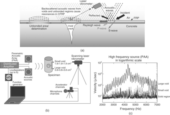
The acoustic-laser technique is a combined acoustic and laser optical tech-nique which remedies an important limitation of acoustic techniques by enabling non-contact, even remote NDT of bonded FRP applications in structural engineering. The technique is based on the principle that local damage such as debonding and voids in the FRP–concrete or FRP–steel interface vibrate differently than intact regions upon an acoustic excitation (Fig. 5.11(a)) (Büyüköztürk et al,. 2012). This difference in the vibration response can be related to the size of damage and the mechanical properties of the FRP. Vibration anomalies remotely measured at the target surface using a laser vibrometer can be used to detect, map, and characterize defects. The technique is effective for bonded thin layered systems, since debonding or voids larger than a certain size respond to the acoustically induced surface waves and display a vibration response depending on the size of debonding. Use of laser vibrometry for sensing the vibration response provides a remote, accurate, and fast method that does not alter the target characteristics. Figure 5.11(b) shows the experimental setup for detecting debonding in GFRP-wrapped concrete cylinders and Fig. 5.11(c) shows the vibration velocities measured at intact and debonded regions as a function of acoustic excitation frequency. As can be seen from the figure, the vibration signatures over the void have higher velocity amplitudes than those of the intact region, the difference being related to the size of the void. Hence, the method has high potential for conducting rapid inspection of bonded FRP applications in structural engineering.
5.4.3 Infrared thermography and digital shearography
Infrared thermography (IRT) and digital shearography (DISH), also known as speckle pattern shearing interferometry (SPSI), are both optical techniques that enable non-contact, full-field, real-time, and rapid non-destructive testing; but these methods are fundamentally different in their damage detection principles. Thermography measures a material’s heat transfer response to thermal effects while shearography measures a material’s mechanical response to stress (Hung et al,. 2009). Both methods are applicable to metals, non-metals, and composite materials for detection of damage and flaws and can be used in a complementary fashion to improve detection capability and accuracy.
Infrared thermography is based on the principle that subsurface anomalies in a material result in localized differences in surface temperature caused by different rates of heat transfer at the defect zones. Thermography senses the emission of thermal radiation from the material surface and produces a visual image from this thermal signal which can be related to the size of an internal defect. Most infrared thermography applications use a thermographic camera in conjunction with an infrared-sensitive detector which images the heat radiation contrasts. Thermographic imaging may involve active or passive sources such as a flash tube or solar radiation. Active thermography can be further divided into four groups based on the excitation techniques: transient pulse thermography, step heating (long pulse thermography), periodic heating (lock-in) thermography, and thermal mechanical vibration thermography (vibrothermography) (Hung et al,. 2009). Use of active thermography improves the applicability and accuracy of the technique, enabling quantitative information regarding subsurface defects. Figure 5.12 shows active thermographic imaging of FRP-bonded concrete for detection of debonding. The obtained images show the potential of the method in detection and sizing of the defects behind single or multiple layers of FRP reinforcement (Cantini et al,. 2012).
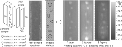
5.12 Infrared thermographic imaging of CFRP-bonded concrete specimen for detection of delamination. (Courtesy of Dr. Lorenzo Cantini, Politecnico di Milano, Italy)
Shearography is an interferometric imaging technique that directly mea-sures the selected first derivatives of specific surface displacement components (components of surface strains) using coherent laser illumination and a charge-coupled device (CCD) camera for recording (Hung et al,. 2009; Lai et al,. 2009).The technique has been used for detection of delaminations, residual stresses, vibration modes, and leakage detection and has gained industrial acceptance as a practical and reliable NDT method. Non-destructive testing using digital shearography involves recording of two states of an object, before and after the application of certain stresses using thermal, acoustic, or pressure loading.
Both IRT and DISH were successfully applied to detection of debonding in FRP-bonded concrete in several studies with up to 90% accuracy in determining the sizes of artificial defects (Hung et al,. 2009; Lai et al,. 2009; Taillade et al,. 2011; Cantini et al,. 2012). Complementary use of these two methods in field applications has the potential to provide effective and cost-efficient non-destructive evaluation of bonded FRP applications in structural engineering.
5.4.4 Microwave NDT
The principle of microwave NDT is to generate and transmit electromagnetic (EM) short pulses or time harmonic waves through a transmitter antenna towards a target medium and record the scattered signals at the receiver antenna. When the transmitted EM waves encounter an object or another medium with different EM properties, some portion of the transmitted energy is reflected from the boundary and the rest is transferred into the new medium undergoing some refraction depending on the material properties of the new medium and the angle of incidence. Thus, the scattered signals recorded at the receiver contain some information about the target’s EM properties, which can be extracted by processing and interpreting the recorded signals (Gunes and Büyüköztürk, 2012). In the microwave NDT method, the ability to image buried inclusions in concrete such as rebars and delaminations requires understanding of concrete as a dielectric material (Rhim and Büyüköztürk, 1998) and application of advanced imaging techniques. The resolution of the image improves with the larger bandwidth of the incident wave (shorter pulse) at the expense of reduced penetration depth due to increased wave attenuation inside the dielectric material. Hence, there is a trade-off between the image resolution and the penetration depth that limits the resolution of the image that can be obtained within a certain depth inside the dielectric material. Conductive materials such as steel rebars do not allow penetration of microwaves, hence, it is not possible to see inside a steel or densely reinforced concrete structure.
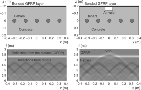
Applications of the microwave NDT method to FRP-bonded concrete have revealed mixed results. Feng et al. (2002) concluded that debonding at the FRP–concrete interface is difficult to detect using plane waves and used dielectric lenses for focusing EM waves on a point in the bonded surface which led to detection of debonded areas. Yu and Büyüköztürk (2008) performed step-frequency radar measurements using plane wave (far field) excitation for detection of debonding in GFRP-bonded concrete cylinders and obtained mildly successful results. The fundamental problem with debonding detection in FRP-bonded concrete is the small thickness of the debonding. Figure 5.13 shows finite difference-time domain simulation of plane microwave scattering by a GFRP-bonded reinforced concrete target with and without a void (Büyüköztürk et al,. 2003). The simulation results clearly indicate the reflection from the void. However, both the measurement conditions and the void size can be quite different in the field. Proper detection (range resolution) of debonding requires that the incident wavelength be half the thickness of debonding, which is typically in the order of a millimeter. A simple calculation shows that the frequency of the incident wave must be about an order of magnitude higher than those used in the above-cited studies for proper detection. An additional limitation for microwave NDT of FRP is that conductive composites such as CFRP do not allow sufficient penetration of microwaves for assessment of bond quality. The method has the advantage of being non-contact and rapid, but further research and applications are needed for successful evaluation of FRP applications in structural engineering.
5.4.5 Embedded sensors for SHM
Structural health monitoring of civil engineering structures using embedded sensors for measuring deformation, pressure, or temperature and detecting damage has been a popular interdisciplinary research field in the last two decades. The embedded sensors include, but are not limited to, passive types of sensors such as fiber optic sensors with many variations such as the fiber optic Bragg grating sensors, pre-embedded concrete bar (PECB) sensors, corrosion sensors and active types of sensors such as the piezoelectric wafer active sensors (Lau, 2003; Giurgiutiu, 2008).
The main component of the optical fiber sensor is a small diameter glass fiber that guides light by confining it within regions having different optical indices of refraction. The sensor is basically formed by the optical fiber, a light source, sensing element, and a detector. When subjected to external perturbations such as strain, pressure, or temperature, the sensing element modulates some parameter of the optical system such as the intensity, wave-length, polarization, or phase which changes the characteristics of the optical signal received at the detector. These changes can then be related to the parameter being measured. The sensors can be embedded within the structural material or bonded to the member surface for real-time damage assessment. As the sensor can serve as both a sensing element and a medium for signal transmission, the electronic instrumentation can be located away from the sensor allowing remote monitoring of structures in localized, multiplexed, or distributed arrangements (Méndez and Csipkes, 2012; Lau, 2003).
The optical fiber Bragg grating (FBG) type sensor is one of the most promising and popular type of sensor that is well suited for structural health monitoring of composite materials and their structural applications. The operating principle of the FBG sensor is illustrated in Fig. 5.14(a) (Miller and Méndez, 2011). Any form of broad-spectrum light passing through the grating has a portion of its energy transmitted through and the rest reflected back as a narrow light signal centered at a certain Bragg wavelength. Any change in the characteristics of light due to external perturbations results in a Bragg wavelength shift, which can be related to the parameter being measured. Small size and environmental durability of these sensors have led to their use in many SHM applications, although alkaline attack to the fiber core in embedded applications and damaging of fibers during field installation is still a serious concern to be addressed (Lau, 2003).
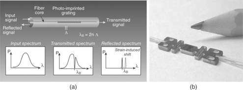
5.14 Principle of operation and transmission and reflection spectra of a fiber Bragg grating (a) and a commercial fiber Bragg grating strain sensor (b). (Courtesy of Dr. Alexis Méndez, Micron Optics, Inc., Atlanta, GA, USA)
Numerous successful laboratory and field applications of fiber optic sensors have been reported in the literature proving their high potential for long-term structural health monitoring of structures (Tennyson et al,. 2000, 2001; Labossiere et al,. 2000; Lau et al,. 2001; Zhao and Ansari, 2002; Lau, 2003; Watkins et al,. 2007; Mehrani et al,. 2009; Jiang et al,. 2010). Figure 5.15 shows one of the longest running SHM applications in structural engineering (Meier, 2012; Meier et al,. 2012). The Stork Bridge in Winterthur, Switzerland, is a cable stay bridge constructed in 1996, which has two stay cables made of CFRP. The cable type used consists of 241 wires, each with a diameter of 5 mm. Although the cable type was fatigue tested in the laboratory for 10 million load cycles, several times greater than that expected during the service life of the bridge, under a load three times greater than the permissible load of the bridge, monitoring the long-term performance of this new material is still of interest to bridge engineers. Figure 5.15(a) shows the bridge, the CFRP cable section and the data acquisition board located in the box girder for SHM. The location and arrangement of FBG sensors are shown in Fig. 5.15(b) and the strain measurement data obtained from both FBG and resistive strain gages (RSG) for a period of 14 years is shown in Fig. 5.15(c).The fluctuation of the strains was observed to be synchronous with the temperature changes and the FBG sensors were observed to be more stable than RSG sensors.
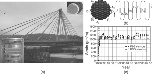
5.15 Structural health monitoring of FRP tendons in Stork Bridge, Switzerland, using embedded sensors: (a) the bridge, CFRP tendons and the data acquisition board inside the box girder; (b) FBG sensor locations and the meander structure; (c) long-term strain measurements over 14 years . (Courtesy of Prof. Urs Meier, EMPA, Switzerland)
Use of embedded sensor technologies with emphasis on fiber optic sensors for SHM is likely to be one of the fastest growing application areas in civil engineering due to its high impact potential in dealing with infrastructure sustainability problems in a cost-efficient manner.
5.4.6 Combined use of different methods
Combination of the capabilities of more than one NDT and/or SHM method in a complementary fashion in order to increase the accuracy and reliability of characterization or damage assessment is a commonly voiced approach in the NDT/SHM research community (Maierhofer et al,. 2010). A RILEM technical committee (TC 207-INR) was recently devoted to this goal. A quick review of the NDT and SHM methods presented in the preceding sections immediately reveals some possible combinations of methods that can be used in a complementary fashion. Infrared thermography and digital shearography methods are an obvious combination that are very similar in their test procedures but fundamentally different in the way they characterize damage. Infrared thermography measures the heat transfer response of materials to thermal excitation while digital shearography measures the mechanical response of materials to stresses. Coherent superposition of information obtained from both methods is likely to produce better characterization of materials and detection of inherent damage.
Another combination of methods that provides complementary information is ultrasonic imaging and microwave (radar) methods. Ultrasonic testing involves propagation of stress waves in materials, governed by the material’s mechanical properties, whereas the microwave method involves propagation of electromagnetic waves in materials, governed by the material’s electromagnetic (dielectric) properties. Stress waves travel easily in dense and moist materials and are reflected by voids in the material. EM waves travel more easily in dry materials, not significantly affected by voids, but are completely reflected by metals. Ultrasonic testing requires contact with the material whereas microwave antennas enable remote testing. Hence, the test procedures and information content provided by these two materials are truly complementary and their combination leads to better evaluation of materials.
Sometimes, combination of methods in the same category facilitates more efficient evaluation. Impact-echo and ultrasonic testing are both stress wave methods that require measurements in contact with the material. Impact-echo provides faster but less accurate evaluation of large areas. Hence, a preliminary survey of a large area using the impact-echo technique can map areas of low wave velocity which can then be tested using the more accurate ultrasonic testing technique. Replacing impact-echo with the acoustic-laser technique can further speed up the evaluation. Potential damage areas mapped by the acoustic-laser technique can be verified using local ultrasonic evaluation.
Combination of SHM and NDT methods can also lead to effective and cost-efficient evaluation of materials and structures. In condition evaluation or damage detection of structures, vibration-based SHM methods that use system identification techniques can detect and locate potential areas of damage which can then be effectively evaluated using local NDT methods. More research in this area is needed for identification of optimum combinations of methods and strategies for fast and accurate evaluation of structures.
5.5 Future trends
FRP applications in structural engineering have come a long way since their inception about three decades ago. There is a growing consensus on the tremendous potential of these materials in addressing the challenges associated with the aging infrastructure all around the world. It is only a matter of time before the civil engineering community becomes comfortably familiar with the behavior and specific failure modes of these materials and their applications in structural engineering, and have at their disposal comprehensive standards that provide proper procedures for safe and reliable design practices. Compared to the likely scene fifty years from now, the current state of knowledge and practice of FRP applications in structural engineering can be considered as only in its infancy. Even now, exciting applications that include innovative hybrid or all FRP solutions to pressing infrastructure challenges continue to spur, instilling optimism about what is to come in the near future.
A key feature of FRP composites that makes them so promising as engineering materials is the opportunity to tailor the material properties through the control of fiber and matrix combinations and the selection of processing techniques. As fiber diameters are reduced, their stiffness and strength, and hence those of the composite material, are increased due to the highly aligned microstructure of the fibers and reduction of the flaws to very small sizes. The glass and carbon fibers commonly used in structural engineering applications have diameters in the order of 10 microns and produce composite elastic modulus in the range of 20–200 GPa (between those of concrete and steel) and tensile strength in the range of 400–2800 MPa (approximately 1–7 times the yield strength of reinforcing steel) (Gunes, 2004). Recent progress in the development of nanofibers and especially nanotubes with diameters in the order of 100 nm and 1–100 nm, respectively, has achieved such drastic improvements in mechanical properties that significant increases in the elastic and strength properties of FRP composites are likely in the near future (Coleman et al,. 2006).
Recent progress in the development of FRP composite materials and embedded sensor technologies are probably the most exciting developments for the future of civil engineering. Marriage of these two technologies paves the way for the development of smart composites and constitutes a foundation for biomimetics in structural design. An intelligent composite structure wired with a network of embedded sensors and actuators that monitors and responds to its own health no longer seems a distant possibility. This popular multi-disciplinary research area is likely to grow rapidly in the near future, leading to more efficient, smart, and sustainable structures.
NDT methods with emphasis on advanced, non-contact, and fast techniques are and will be an indispensable tool for condition evaluation and damage assessment of existing structures. There is much room for further research and development in an effort to improve the capabilities of current NDT techniques and their combined use with complementary methods and strategies for better material characterization and damage assessment.
5.6 Conclusion
Civil engineering is in the midst of a transition era in which FRP com-posite materials gradually gain acceptance as a new class of materials, superior in many ways to conventional construction materials. Realizing the potential of these materials in rehabilitation and upgrading of existing structures and building more durable and sustainable new structures depends on the characterization of their behavior and failure modes and the development of comprehensive codes and guidelines covering all aspects of their specification and design. Failure behavior of FRP applications to compression, tension, and flexural members are reviewed in this chapter together with various preventive measures. Developments in NDT and SHM methods for effective materials characterization, damage assessment and health monitoring of FRP applications are an essential component of their acceptance and common use by the civil engineering community.
5.7 Acknowledgment
The author gratefully acknowledges the mentorship provided by Prof. Oral Büyüköztürk, who was the principal investigator in many projects presented herein, and the collaboration and support by the former and current members of the Infrastructure Science and Technology research group at MIT. Appreciation is extended to Prof. Urs Meier, Prof. Issam Harik, Dr. Lorenzo Cantini and Dr. Alexis Méndez for their kind contributions with illustrative images from their research. Special thanks go to Prof. Nasim Uddin, the editor, and Ms. Lucy Beg, the publisher’s coordinator, for their incredible patience and support.
5.8 Sources of further information
Additional information regarding the contents of this chapter can be obtained from the publications and websites listed below.
Büyüköztürk, O., Ta![]() demir, M.A., Güne
demir, M.A., Güne![]() , O., Akkaya, Y., eds. Nondestructive Testing of Materials and Structures, Vol. 6. Dordrecht: Springer, 2012. [RILEM Bookseries].
, O., Akkaya, Y., eds. Nondestructive Testing of Materials and Structures, Vol. 6. Dordrecht: Springer, 2012. [RILEM Bookseries].
Karbhari V.M., Lee L.S., eds. Service Life Estimation and Extension of Civil Engineering Structures. Woodhead Publishing: Cambridge, 2011.
Barbero, E.J. Introduction to Composite Materials Design, 2nd ed. Boca Raton, FL: CRC Press; 2010.
Grosse C.U., Ohtsu M., eds. Acoustic Emission Testing. Berlin: Springer, 2010.
Knops, M. Analysis of Failure in Fiber Polymer Laminates: The Theory of Alfred Puck. New York: Springer; 2010.
Ochoa, O.O., Reddy, J.N. Finite Element Analysis of Composite Laminates. Dordrecht: Kluwer Academic Publishers; 2010.
Giurgiutiu, V. Structural Health Monitoring with Piezoelectric Wafer Active Sensors. Burlington, MA: Elsevier Academic Press; 2008.
Kundu T., ed. Advanced Ultrasonic Methods for Material and Structure Inspection. London: ISTA Publishing, 2007.
Hinton, M., Soden, P.D., Kaddour, A.-S. Failure Criteria in Fibre-Reinforced-Polymer Composites. London: Elsevier; 2004.
Oehlers, D., Seracino, R. Design of FRP and Steel Plated RC Structures: Retrofitting Beams and Slabs for Strength, Stiffness and Ductility. Oxford: Elsevier; 2004.
Teng, J.G., Chen, J.F., Smith, S.T., Lam, L. FRP strengthened RC structures. Hoboken, NJ: John Wiley and Sons; 2002.
Hollaway, L.C., Head, P.R. Advanced Polymer Composites and Polymers in the Civil Infrastructure. Oxford: Elsevier; 2001.
Peters, S.T. Handbook of Composites, 2nd edn. London: Chapman and Hall; 1997.
Dong, Y., Ansari, F., Non-destructive testing and evaluation (NDT/NDE) of civil structures rehabilitated using fiber reinforced polymer (FRP) compositesKarbhari, V.M., Lee, L.S., eds. Service Life Estimation and Extension of Civil Engineering Structures. Woodhead Publishing, Cambridge, 2011:193–222.
Maierhofer, C., Kohl, C., Wöstmann, J., Combining the results of various non-destructive evaluation techniques for reinforced concrete: data fusionMaierhofer, C., Reinhardt, H.-W., Dobmann, G., eds. Non-destructive Evaluation of Reinforced Concrete Structures, Volume 2: Nondestructive Testing Methods. Woodhead Publishing, Cambridge, 2010:95–107.
Hollaway, L.C. A review of the present and future utilisation of FRP composites in the civil infrastructure with reference to their important in-service properties. Construction and Building Materials. 2010; 24(12):2419–2445.
Pendhari, S.S., Kant, T., Desai, Y.M. Application of polymer composites in civil construction: a general review. Composite Structures. 2008; 84(2):114–124.
Zhao, X.-L., Zhang, L. State-of-the-art review on FRP strengthened steel structures. Engineering Structures. 2007; 29(8):1808–1823.
Coleman, J.N., Khan, U., Blau, W.J. Small but strong: a review of the mechanical properties of carbon nanotube-polymer composites. Carbon. 2006; 44(9):1624–1652.
Büyüköztürk, O., Gunes, O., Karaca, E. Progress review on understanding debonding problems in reinforced concrete and steel members strengthened using FRP composites. Construction and Building Materials. 2004; 18(1):9–19.
Lau, K.T. Fibre-optic sensors and smart composites for concrete applications. Magazine of Concrete Research. 2003; 55(1):19–34.
Tennyson, R.C., Coroy, T., Duck, G., Manuelpillai, G., Mulvihill, P., Cooper, D.J.F., Smith, P.W.E., Mufti, A.A., Jalali, S.J. Fibre optic sensors in civil engineering structures. Canadian J of Civil Engineering. 2000; 27(5):880–889.
Zadeh, A.A. Practicality and capability of NDT in evaluating long-term durability of FRP repairs on concrete bridges. Vancouver, Canada: Department of Civil Engineering, University of British Columbia; 2009. [M.Sc. Thesis].
Rao, M.R.P.D. Review of nondestructive evaluation techniques for FRP composite structural components. Morgantown, WV: Department of Civil and Environmental Engineering, West Virginia University; 2007. [M.Sc. Thesis].
Gunes, O. A fracture based approach to understanding debonding in FRP bonded structural members. Cambridge, MA: Massachusetts Institute of Technology; 2004. [PhD thesis].
5.9 References
ACI 440. Guide for the design and construction of externally bonded FRP systems for strengthening concrete structures. ACI 440.2R-02, American Concrete Institute, Farmington Hills, MI. 2002.
Au, C., Büyüköztürk, O. Effect of fiber orientation and ply mix on fiber reinforced polymer-confined concrete. J Composites for Construction. 2005; 9(5):397–407.
Barbero, E.J. Introduction to Composite Materials Design, 2nd edn. Boca Raton: FL, CRC Press; 2010.
Bisby, L.A., Dent, A.J.S., Green, M.F. Comparison of confinement models for fiber-reinforced polymer-wrapped concrete. ACI Structural J. 2005; 102(1):62–72.
Blitz, J., Simpson, G. Ultrasonic Methods of Non-destructive Testing. London: Chapman & Hall; 1996.
Büyüköztürk, O. Imaging of concrete structures. NDT & E International. 1998; 31(4):233–243.
Büyüköztürk, O., Hearing, B. Failure behavior of precracked concrete beams retrofitted with FRP. J Composites for Construction. 1998; 2(3):138–144.
Büyüköztürk, O., Park, J., Au, C. ‘Non-destructive evaluation of FRP-confined concrete using microwaves’, Proceedings of the International Sym posium on Non-Destructive Testing in Civil Engineering (NDT-CE 2003). Berlin, Germany, September. 2003; 13:2003.
Büyüköztürk, O., Gunes, O., Karaca, E. Progress review on understanding debonding problems in reinforced concrete and steel members strengthened using FRP composites. Construction and Building Materials. 2004; 18(1):9–19.
Büyüköztürk, O., Haupt, R., Tuakta, C., Chen, J., Remote detection of debonding in FRP-strengthened concrete structures using acoustic-laser techniqueBüyüköztürk, O., Ta![]() demir, A., Güne
demir, A., Güne![]() , O., Akkaya, Y., eds. Nondestructive Testing of Materials and Structures, Vol. 6. Dordrecht: Springer, 2012. [RILEM Bookseries].
, O., Akkaya, Y., eds. Nondestructive Testing of Materials and Structures, Vol. 6. Dordrecht: Springer, 2012. [RILEM Bookseries].
Cantini, L., Cucchi, M., Fava, G., Poggi, C., Damage and defect detection through infrared thermography of fiber composites applications for strengthening of structural elementsBüyüköztürk, O., Ta![]() demir, A., Güne
demir, A., Güne![]() , O., Akkaya, Y., eds. Nondestructive Testing of Materials and Structures, Vol. 6. Dordrecht: Springer, 2012. [RILEM Bookseries].
, O., Akkaya, Y., eds. Nondestructive Testing of Materials and Structures, Vol. 6. Dordrecht: Springer, 2012. [RILEM Bookseries].
Carpinteri, A., Lacidogna, G., Paggi, M. Acoustic emission monitoring and numerical modeling of FRP delamination in RC beams with non-rectangular cross-section. Materials and Structures. 2007; 40(6):553–566.
Cartz, L. Nondestructive Testing: Radiography Ultrasonics Liquid Penetrant, Magnetic Particle, Eddy Current. Materials Park, OH: ASM International; 1995.
Coleman, J.N., Khan, U., Blau, W.J., Gun’ko, Y.K. Small but strong:A review of the mechanical properties of carbon nanotube-polymer composites. Carbon. 2006; 44(9):1624–1652.
Colomb, F., Tobbi, H., Ferrier, E., Hamelin, P. Seismic retrofit of reinforced concrete short columns by CFRP materials. Composite Structures. 2008; 82:475–487.
Czaderski, C., Motavalli, M. ‘40-Year-old full-scale concrete bridge girder strengthened with prestressed. CFRP plates anchored using gradient method’, Composites Part B – Engineering. 2007; 38(7–8):878–886.
Davila, C.G., Camanho, P.P., Rose, C.A. Failure criteria for FRP laminates. J Composite Materials. 2005; 39(4):323–345.
Dong, Y., Ansari, F. Non-destructive testing and evaluation (NDT/NDE) of civil structures rehabilitated using fi ber reinforced polymer (FRP) composites. In: Karbhari V.M., Lee L.S., eds. Service Life Estimation and Extension of Civil Engineering Structures. Cambridge: Woodhead Publishing; 2011:193–222.
Feng, M.Q., De Flaviis, F., Kim, Y.J. Use of microwaves for damage detection of fiber reinforced polymer-wrapped concrete structures. J of Engineering Mechanics – ASCE. 2002; 128(2):172–183.
Giurgiutiu, V. Structural Health Monitoring with Piezoelectric Wafer Active Sensors. Burlington, MA: Elsevier Academic Press; 2008.
Grosse C.U., Ohtsu M., eds. Acoustic Emission Testing. Berlin: Springer, 2010.
Gunes, B., Gunes, O. Structural health monitoring and damage assess-ment. Part II: Application of the damage locating vector (DLV) method to the ASCE benchmark structure experimental data. Int J Phys Sci. 2012; 7(9):1509–1515.
Gunes, B., Gunes, O. Structural health monitoring and damage assess-men Part I:A critical review of approaches and methods’. Int J Phys Sci. 2013. [in press].
Gunes, O. A fracture based approach to understanding debonding in FRP bonded structural members. Cambridge, MA: Massachusetts Institute of Technology; 2004. [PhD thesis].
Gunes, O., Büyüköztürk, O. Simulation-based microwave imaging of plain and reinforced concrete for nondestructive evaluation. Int J Phys Sci. 2012; 7(3):383–393.
Gunes, O., Büyüköztürk, O., Karaca, E. A fracture-based model for FRP debonding in strengthened beams. Engineering Fracture Mechanics. 2009; 76(12):1897–1909.
Gunes, O., Lau, D., Tuakta, C., Büyüköztürk, O., Construction and Building Materials. Ductility of FRP-concrete systems: Investigations at different length scales, 2013. http://dx.doi.org/10.1016/j.comboildmat.2012.10.017
Gunes, O., Tumer, R., Gunes, B., Faraji, S., Performance-based seismic retrofit design for RC frames using FRP composite materials. Structural Engineering and Mechanics. 2013.
Harik, I., Peiris, A., Case studies of structural health monitoring of bridgesBüyüköztürk, O., Ta![]() demir, A., Güne
demir, A., Güne![]() , O., Akkaya, Y., eds. Nondestructive Testing of Materials and Structures, Vol. 6. Dordrecht: Springer, 2012. [RILEM Bookseries].
, O., Akkaya, Y., eds. Nondestructive Testing of Materials and Structures, Vol. 6. Dordrecht: Springer, 2012. [RILEM Bookseries].
Hinton, M., Soden, P.D., Kaddour, A.-S. Failure Criteria in Fibre-Reinforced-Polymer Composites: The World-Wide Failure Exercise. London: Elsevier; 2004.
Hull, D., Clyne, T.W. An Introduction to Composite Materials. Cambridge: Cambridge University Press; 1996.
Hung, Y.Y., Chen, Y.S., Ng, S.P., Liu, L., Huang, Y.H., Luk, B.L., Ip, R.W.L., Wu, C.M.L., Chung, P.S. Review and comparison of shearography and active ther-mography for nondestructive evaluation. Materials Science & Engineering R-Reports. 2009; 64(5–6):73–112.
Jiang, G., Dawood, M., Peters, K., Rizkalla, S. Global and local fiber optic sensors for health monitoring of civil engineering infrastructure retrofit with FRP materials. Structural Health Monitoring. 2010; 9(4):309–322.
Knops, M. Analysis of Failure in Fiber Polymer Laminates: The Theory of Alfred Puck. New York: Springer; 2010.
Kundu T., ed. Advanced Ultrasonic Methods for Material and Structure Inspection. London: ISTA Publishing, 2007.
Kundu, T., Guided waves for nondestructive testing – experiment and analysis NDTMS-2011Büyüköztürk O., Tas¸demir A., Günes O., Akkaya Y., eds. Proceedings of the International Symposium on Nondestructive Testing ofMaterials and Structures. Istanbul Technical University, Istanbul,Turkey; Vol. 6. Springer, Dordrecht, The Netherlands., 2012. [RILEM Bookseries].
Labossiere, P., Neale, K.W., Rochette, P., Demers, M., Lamothe, P., Lapierre, P., Desgagné, G. Fibre reinforced polymer strengthening of the Sainte-Emelie-de-l’Energie bridge: design, instrumentation, and field testing. Canadian J of Civil Engineering. 2000; 27(5):916–927.
Lai, W.L., Kou, S.C., Poon, C.S., Tsang, W.F., Ng, S.P. Characterization of flaws embedded in externally bonded CFRP on concrete beams by infrared thermography and shearography. J of Nondestructive Evaluation. 2009; 28(1):27–35.
Lau, K.T. Fibre-optic sensors and smart composites for concrete applications. Magazine of Concrete Research. 2003; 55(1):19–34.
Lau, K.T., Yuan, L.B., Zhou, L.M., Wu, J.S., Woo, C.H. Strain monitoring in FRP laminates and concrete beams using FBG sensors. Composite Structures. 2001; 51(1):9–20.
Maalej, M., Tanwongsval, P., Paramasivam, P. Modelling of rectangular RC columns strengthened with FRP. Cement & Concrete Composites. 2003; 25:263–276.
Maierhofer, C., Kohl, C., Wöstmann, J. Combining the results of various non-destructive evaluation techniques for reinforced concrete:data fusion. In: Maierhofer C., Reinhardt H.-W., Dobmann G., eds. Non-Destructive Evaluation of Reinforced Concrete Structures, Volume 2: Non-Destructive Testing Methods. Cambridge: Woodhead Publishing; 2010:95–107.
Mehrani, E., Ayoub, A., Ayoub, A. Evaluation of fiber optic sensors for remote health monitoring of bridge structures. Materials and Structures. 2009; 42(2):183–199.
Meier, U. Carbon fiber reinforced polymer cables: Why? Why Not? What If? Arabian J of Science and Engineering. 2012; 37:399–411.
Meier, U., Brönnimann, R., Anderegg, P., Terrasi, G.P., 20 years of experience with structural health monitoring of objects with CFRP componentsBüyüköztürk, O., Ta![]() demir, A., Güne
demir, A., Güne![]() , A., Akkaya, Y., eds. Nondestructive Testing of Materials and Structures, Vol. 6. Dordrecht: Springer, 2012. [RILEM Bookseries].
, A., Akkaya, Y., eds. Nondestructive Testing of Materials and Structures, Vol. 6. Dordrecht: Springer, 2012. [RILEM Bookseries].
Méndez, A., Csipkes, A., Overview of fiber optic sensors for NDT applica-tionsBüyüköztürk, O., Tasdemir, A., Güne![]() , O., Akkaya, Y., eds. Nondestructive Testing of Materials and Structures, Vol. 6. Dordrecht: Springer, 2012. [RILEM Bookseries].
, O., Akkaya, Y., eds. Nondestructive Testing of Materials and Structures, Vol. 6. Dordrecht: Springer, 2012. [RILEM Bookseries].
Miller, J.W., Méndez, A. Fiber Bragg grating sensors: market overview and new perspectives. In: Cusano A., Cutolo A., Alberts J., eds. Fiber Bragg Grating Sensors: Recent Advancements, Industrial Applications and Market Exploitation. London: Bentham Press, 2011.
Mirmiran, A., Shahawy, M., El Echary, H. Acoustic emission monitoring of hybrid FRP-concrete columns. J of Engineering Mechanics – ASCE. 1999; 125(8):899–905.
Ochoa, O.O., Reddy, J.N. Finite Element Analysis of Composite Laminates. Dordrecht: Kluwer Academic Publishers; 2010.
Peters, S.T. Handbook of Composites, 2nd edn. London: Chapman and Hall; 1997.
Ramirez, G., Ziehl, P.H., Fowler, T.J. Nondestructive evaluation of full-scale FRP bridge beams prior to construction. Research in Nondestructive Evaluation. 2009; 20(1):32–50.
Rhim, H.C., Büyüköztürk, O. Electromagnetic properties of concrete at microwave frequency range. ACI Materials J. 1998; 95(3):262–271.
Suresh, S. Fatigue of Materials, 2nd edn. Cambridge: Cambridge University Press; 1998.
Sweeney, R.A.P., Update on Fatigue Issues at Canadian National RailwaysRemaining Fatigue Life of Steel Structures. Lausanne: IABSE Workshop, 1990.
Taillade, F., Quiertant, M., Benzarti, K., Aubagnac, C. Shearography and pulsed stimulated infrared thermography applied to a nondestructive evaluation of FRP strengthening systems bonded on concrete structures. Construction and Building Materials. 2011; 25(2):568–574.
Tawhed, W.F., Gassman, S.L. Damage assessment of concrete bridge decks using impact-echo method. ACI Materials J. 2002; 99(3):273–281.
Tennyson, R.C., Coroy, T., Duck, G., Manuelpillai, G., Mulvihill, P., Cooper, D.J.F., Smith, P.W.E., Mufti, A.A., Jalali, S.J. Fibre optic sensors in civil engineering structures. Canadian J of Civil Engineering. 2000; 27(5):880–889.
Tennyson, R.C., Mufti, A.A., Rizkalla, S., Tadros, G., Benmokrane, B. Struc-tural health monitoring of innovative bridges in Canada with fiber optic sensors. Smart Materials & Structures. 2001; 10(3):560–573.
Triantafillou, T.C. Composites: A new possibility for the shear strengthening of concrete, masonry and wood. Composites Science and Technology. 1998; 58(8):1285–1295.
Watkins, S.E., Fonda, J.W., Nanni, A. Assessment of an instrumented reinforced-concrete bridge with fiber-reinforced-polymer strengthening. Optical Engineering. 2007; 46(5):051010.
Yu, T.-Y., Büyüköztürk, O. A far-field airborne radar NDT technique for detecting debonding in GFRP-retrofitted concrete structures. NDT&E Int. 2008; 41(1):10–24.
Zhao, X.-L., Zhang, L. State-of-the-art review on FRP strengthened steel structures. Engineering Structures. 2007; 29(8):1808–1823.
Zhao, Y., Ansari, F. ‘Embedded fiber optic sensor for characterization of interface strains in. FRP composite’, Sensors and Actuators A – Physical. 2002; 100(2–3):247–251.