Error correction is one of the most advanced areas in the entire field of digital audio. It is purely because of error-correction techniques that reliable digital recordings can be made, despite the frequent occurrence of tape dropouts.
In the next two sections, we will discuss the theory behind the EIAJ format P, Q and CRC codes. Because of the special nature and the complexity involved, a mathematical treatment of this topic is unavoidable. However, every attempt has been made to pool all the material together in a concise and systematic manner. Examples are included to make the situations more vivid. The only prerequisite in reading them is some knowledge of matrix algebra.
P, Q and the cyclic redundancy check code
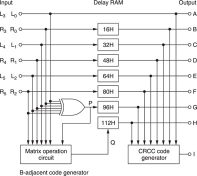
In Figure A1.1, the P codes are generated by feeding the input data L0–R2 to an exclusive-or gate. Hence, we have:

The symbol ⊕ (ring-sum) indicates modulo-2 summation, and obeys the following rules:

which is an exclusive-or operation. When considering expression A1.1 and applying the rules, the parity bit P0 will be 0 for even numbers of logic levels, and 1 for odd numbers.
Q codes are generated by a matrix operation circuit, the principle of which is shown in Figure A1.2.

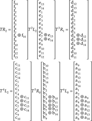
Initially, L0, a 14-bit data word comprising bits a1–a14, is applied to the summing nodes and the shift register contents are all zeros. After one shift to the right, the shift register contents change to those shown in Figure A1.3. The single shift operation on word L0 can be defined as TL0.
Now, a second data word R0, comprising bits b1–b14, is applied to the summing nodes. When the next shift occurs, the shift register contents change to those shown in Figure A1.4. This time, L0 undergoes two shifts while R0 is subjected to only one; the combined effect can be defined as TTL0 ⊕ TR0, or T2L0 ⊕ TR0.
After six shift operations, the shift register contents constitute the code word Q0. Mathematically, we can write:
![]()
Similarly, we have
![]()
and
![]()
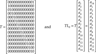
The 1-bit shift and 2-bit modulo-3 summation are functions of T having the following forms:


If we let

then we have the following:
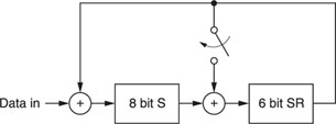
Now, let us see how a Q code can be generated if data are input serially. Consider the following scheme:
1 |
One of the feedback loops is controlled by a switch that turns on whenever 15 shifts are made. |
2 |
The exclusive-or operation is only active during a shift register (SR) shift. |
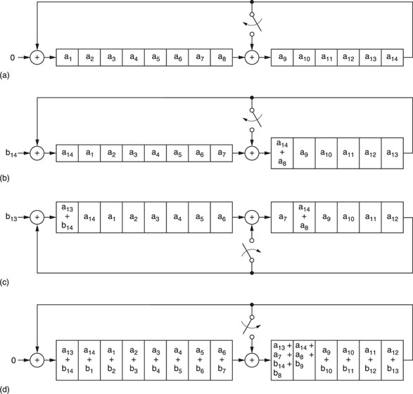
The configuration shown in Figure A1.5 applies.
Then, after 14 shifts the contents of the two SRs are as shown in Figure A1.6a. For an additional shift we have the situation shown in Figure A1.6b, which we recognize as TL0. As we continue, we have the situation shown in Figure A1.6c. After the 30th shift, the contents of the SRs are as shown in Figure A1.6d which is T2L0 + TR3 (when compared with the two column matrices TR2 and T2L2). Note that for this scheme to work, the serial data have to be sent in the following format:
a14a13a12a11…a1 bb14b13b1 bc14c13
where b = 0. Finally, the reader can easily verify that, after 90 shifts, the contents of the two SRs constitute the word Q.
The PCM-F1 employs cyclic redundancy check code (CRCC) for detecting code errors. The encoding can be easily implemented by using shift registers, while the decoding scheme becomes simple because of the inherent well-defined mathematical structure. In mathematical terms, a code word is a code vector because it is an n-tuple from the vector space of all n-tuples. For a linear code C with length n and containing r information digits, if an n-tuple
V(1) = (Vn – 1, V1, …, Vn – 2)
obtained by shifting the code vector of C
V = (V0, V1, V2, …, Vn – 1)
cyclically one place to the right is also a code vector of C, then linear code C is called a cyclic code. From this definition, it follows that no matter how many times the digits in V are shifted
cyclically to the right, the resulting n-tuple is also a code vector. The components of a code vector define the coefficients of a polynomial. Therefore, if we denote V(X) as the code polynomial of V, we then have:
V(X) = V0 + V1X + V2X2 + … + Vn – 1Xn – 1
or, in a particular case, where we have the code word shown in Figure A1.7, the code polynomial is written as
V(X) = X11 + X10 + X8 + X5 + X3 + 1
where + stands for modulo-2 summation. Moreover, every code polynomial V(X) can be expressed in the following form:
where M0, M1, …, Mr – 1 are the information digits to be encoded and g(X) is defined as a generator polynomial. Hence, the encoding of a message M(X) is equivalent to multiplying it by g(X). Note that in any particular cyclic code, there only exists one generator polynomial g(X). However, if we encode the information digits according to Equation A1.2, the orders of the message digits are altered. Hence, a different scheme must be used. The code can be put into a systematic form (see Example 3 below) by first multiplying M(X) by xn – r and then dividing the result by g(X), hence,
Xn – rM(X) = Q(X)g(X) + R(X)
Adding R(X) to both sides, we have
![]()
where Q(X) is the quotient and R(X) is the remainder.
In modulo-2 summation, R(X) + R(X) = 0.
If we define the left-hand side of Equation A1.3 as our transmission polynomial T(X), then
T(X) = Q(X)g(X)
which means that T(X) can be divided exactly by g(X). In this case, the encoding is equivalent to converting the information polynomial M(X) into T(X).
If, in the recording process, T(X) changes to E(X) then errors are detected. In the PCM-F1, when the CRCC indicates that one word in a horizontal scanning period H is incorrect, the remaining words in that period will also be considered erroneous.
At this point, it is natural to ask what kind of properties g(X) must have in order to generate an (n, r) cyclic code, i.e., generating an n-bit code from a message of r bits. We have the following theorem.
Theorem. If g(X) is a polynomial of degree n – r and is a factor of Xn+ 1, then g(X) generates an (n, r) cyclic code.

Now, we will show how a 4-bit cyclic code can be generated from a message of 3 bits. We hope that the whole situation will be clarified by the following simple examples.
Example 1. Since n = 4 and r = 3, we are searching for a polynomial of degree 1. Because:
X4 + 1 = (X + 1)(X3 + X2 + X + 1)
our g(X) will be X + 1. Note that g(X) is primitive (irreducible).
Example 2. Consider the messages 000, 100, 010, …, 111 where the LSB is at the extreme left of each word. From Equation A1.2, we have
for 100, V(X) = 1(1 + X) = 1 + X
for 101, V(X) = (1 + X2)(1 + X) = 1 + X + X2 + X3
For these two cases, the coded words are 1100 and 1111 respectively. Proceeding as before, we have the following:
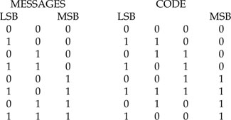
This code has a minimum distance of 2, hence it can detect a single error in the message; it is not systematic, i.e., we do not have a code where the first three digits are the unaltered message digits and the last one is a check bit.
It is not difficult to see that this code can be implemented by the circuit shown in Figure A1.8, which employs two exclusive-or gates and two SRs. For this scheme to work, the message should be input as:
M1M2M3M10M1 ′M2 ′M3 ′M1 ′0… etc.
The SRs reset whenever five shifts are made.

The decoder has the configuration shown in Figure A1.9.
After four data bits come out of the AND gate, we look at the fourth bit. If this bit is zero, the three message bits are considered correct; otherwise, an error is made. Hence, the SRs reset after every four shifts. Also, the message input sequence is:
C1C2C3C4C1 ′C2 ′C3 ′C4 ′… etc.
The circuit works because when we multiply a1a2a3 by 11 we get the following:
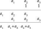
Hence, with the circuit shown in Figure A1.10, in the second shift, a1 is out.
From these five shifts, we get 0, a1, a1+ a2, a2+ a3, which matches the elements generated by the multiplication.
However, for this to work, the message input must have the following format:
M1M2M3M10M1 ′M3 ′M1 ′0…
and the SRs reset whenever five shifts are made.
Hence, for the decoded message D1D2D3, we have:
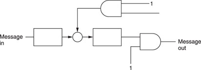

D2 = ((a1 · 1) + a2) · 1
D3 = (((a1 · 1) + a2) · 1 + a3) · 1
Also,
R = D3+ a4
For zero error detection, D3= a4. This is true when we look at the LSB columns of the message and code table. It is also clear that the decoder circuit implements the above division.
Example 3. We can form a systematic code by using Equation A1.3. Take the last message word (1110 in the above example), then the message polynomial is M(X) = 1 + X + X2. Since Xn – r = X in this case, we have XM(X) = X + X2 + X3.
Dividing XM(X) by the generator polynomial g(X) = 1 + X, we have
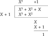
The remainder R(X) = 1. Thus, the code polynomial is
T(X) = X3 + X2 + X + 1
which is 1111.
Proceeding as before, we get the following systematic code:
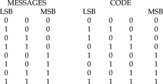
Assuming that message bits are input as
M1M20M1 ′M2 ′M3 ′M0…
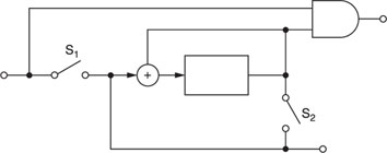
The code can be implemented by the circuit shown in Figure A1.11.
Initially, S2 is off and S1 is on. After M3 is fed into the circuit, S1 switches off, S2 turns on and an additional shift by the SR generates the parity check code. Then, S2 switches off and S1 turns on to repeat the process (Figure A1.12).
The decoder operates in the same manner as the encoder. However, an AND gate is inserted to check the parity received and the one generated by the SR. If they do not match, an error is detected.
Erasure and b-adjacent decoding
After the CRCC decoder detects a code error in each data block, error correction is implemented in the parity decoder. First, the syndrome SP0 (corrector) is calculated as follows:
SP0= L0+ R0+ L1+ L2+ P0
where
P0= L0+ R0+ L1+ R1+ L2+ R2
If there is no error, SP0 = 0, because in modulo-2 summation, adding any two identical quantities is zero.
On the other hand, suppose a single error R1′ (i.e., all 16 bits are incorrect) in a single message block is made. In this case, SP0 = 1.
If we add this to R1′, correction can be made because:
If R1x = 0, R1,x = 1 where R1x is any bit in R1
R1x = 1, R1,x = 0 where R1,x is any bit in R1
and, in either case, we have R1′ + SP0= R1. However, if two errors occur, this method of correction – called the erase method – fails to recover the original information. Since interleaving is employed in the PCM-F1, original bits in a block are shuffled to the other blocks by a 16H delay. Effectively, this method is capable of correcting errors occurring successively in 2048 bits.
In b-adjacent decoding, the syndromes SP0 and SQ0 are calculated as follows:
![]()
where
P0= L0+ R0+ L1+ R1+ L2 + R2*
Q0= T6L0+ T5R0+ T4L1+ T3R1+ T2L2+ TR2r *
*L0r, …, R2r, P0r, Q0r are the information received.
Suppose the received information R1r and R2r contain errors, then:
![]()
where R1 and R2 are the original messages transmitted, and ER1 and ER2 are the errors added.
Substituting R1 ′and R2 ′in place of R1r and R2r in Equations A1.4 and A1.5, we can easily get
![]()
Adding T–1 to both sides of Equation A1.9, then
![]()
Adding SP0 to both sides of Equation A1.10, we get

Rearranging Equation A1.11, we get:
![]()
And from Equation A1.8:
Before we go on, let us summarize the situation as follows: we first calculate the syndromes SP0 and SQ0 according to Equations A1.4 and A1.5. After some algebraic manipulations (if only two or less errors are made during the transmission of data), the error pattern can be calculated using Equations A1.12 and A1.13. Once these are known, we can correct the error using Equations A1.6 and A1.7, where:
R1= R1′ + ER1
R2= R2′ + ER2
Note that in modulo-2 summation, since 1 + 1 = 0, 1 = –1. By this method, 4096 successive bit errors can be corrected.
In what follows we shall demonstrate how the decoding is done by going through an example.
Unfortunately, the matrix T consists of 14 × 14 elements. Even for a simple example such as that shown below, a lot of algebraic manipulations are involved. Therefore, in order to avoid the many steps of purely mechanical computation from clouding the main issue, we shall show only the important steps or results. Anyway, what is important here is to get a ‘feel’ of how decoding is carried out.
Example. We have the following data:
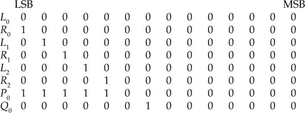
Suppose that, after the data are transmitted, the received data become:
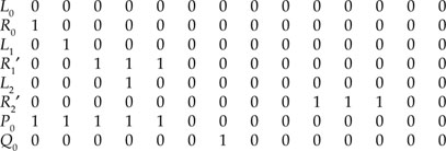
We can find ER1 and ER2 as follows.
First, we have to find SP0 and SQ0. Using Equation A1.4 it is easy to see that

Similarly, from Equation A1.5 and the column matrices TR2, T2L2, …, T6L0 listed in the previous section, we find

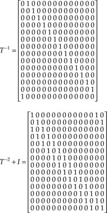
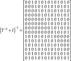
After going through some algebraic manipulations, we find T – 1, (T2 + 1) and finally (T2 + 1)–1. We have
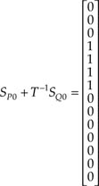
Moreover, using Equation A1.12, we obtain:

and finally from Equation A1.13,

Now, it can be verified that by taking the modulo-2 summation of R1 ′and ER1, R2 and RR2, the correct transmitted data are obtained.
Notes
1. (T2 + 1)–1 can be constructed as follows:
We have
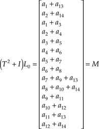
Because (T2 = 1)1, M = L0, then for the first row of (T2 + 1)–1 we must have
[0 0 1 0 1 0 1 0 1 0 1 0 1 0]
so that
[1 0 0 1 0 1 0 1 0 1 0 1 0 1 0] M = a1
2. We can find T–1 and (T2 + 1) in a manner similar to the above.
3. It can be verified easily that (T2 + 1)–1(T2 + 1) = 1.
When we multiply the first row and the first matrix by the first column of the second one, we have
(0.1) + (0.0) + (1.1) + (0.0) + (1.0) + (0.0) + (1.0) + (0.0) + (1.0) + (0.0) + (1.0) + (0.0) + (1.0) + (0.0) = 1
Thus, the first element of the matrix is 1. Similarly, we can verify that all the other elements, except the ones at the diagonal, are zero.
Q0= T6L0+ T5R0+ T4L1 + T3R1+ T2L2+ TR2
