
5
Programming Techniques in Verilog II
5.1 Programming Techniques in Verilog II
Verilog is a Hardware Description language (HDL) used to illustrate a digital system such as a microprocessor, flip-flops (F/Fs), network switch, memory, etc. The Verilog language can be used to describe any digital hardware at any level. The circuit designs developed using HDL are not dependent on technology, are more helpful than schematics and are very simple for debugging and designing, especially for huge circuits. In this chapter, the dataflow model of the circuit is described with the help of different types of circuits.
5.2 Dataflow Model of Circuits
Dataflow modeling does not explain the combinational circuits logic gate. It describes the Boolean funtion of output variable in terms of input variables using operators available in the Verilog library. Here, the data flows from register to register. It requires lesser design steps in comparison to the gate-level model. A number of operators are used by dataflow modeling for the operator to produce the desired results. The model makes use of continuous assignments with the keyword “assign.”
HDL Operators for the dataflow model include:
- + Binary addition
- − Binary subtraction
- & Bit – wise AND
- | Bit – wise OR
- ^ Bit – wise XOR
- ~ Bit – wise NOT
- ?: Conditional
5.3 Dataflow Model of Combinational Circuits
Adder and Subtractor
Multiplexer
Decoder
Comparator
5.3.1 Adder and Subtractor
5.3.1.1 Half Adder
In a half-adder circuit, X and Y are the inputs, however S and C are the outputs. For two inputs, there are four possibilities: 00, 01, 10, 11. All four possible combinations, as well as corresponding outputs, are described in Table 5.1 [1].
Table 5.1 Half adder.
| Inputs | Outputs | ||
|---|---|---|---|
| X | Y | S | C |
| 0 | 0 | 0 | 0 |
| 0 | 1 | 1 | 0 |
| 1 | 0 | 1 | 0 |
| 1 | 1 | 0 | 1 |
Dataflow description of the half adder
Based on the observations given in Table 5.1, the Boolean expression for a half adder is defined as follows:

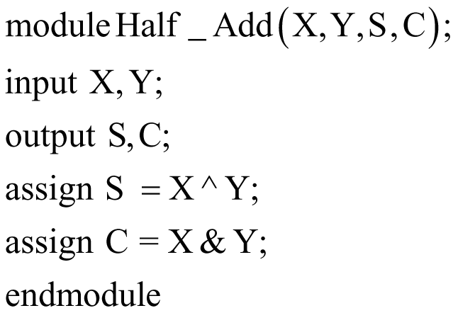
Verilog Code
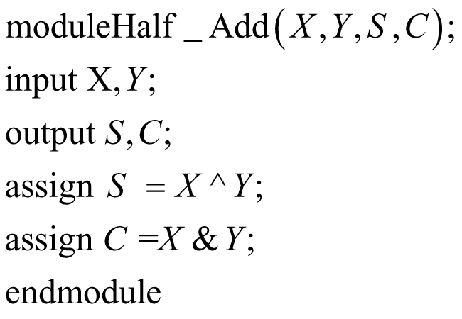
In Verilog code of half adder using dataflow modeling, inputs and outputs are defined inside the module Half_Add. Inside the module, two logic continuous assignments, keyword assign, are called (2).
5.3.1.2 Half Subtractor
In a half-adder circuit,
Table 5.2 Half subtractor.
| Inputs | Outputs | ||
|---|---|---|---|
| X | Y | D | B |
| 0 | 0 | 0 | 0 |
| 0 | 1 | 1 | 1 |
| 1 | 0 | 1 | 0 |
| 1 | 1 | 0 | 0 |
Based on the observations given in Table 5.2, the Boolean expression for a half subtractor is defined as follows:
The difference,
Verilog Code
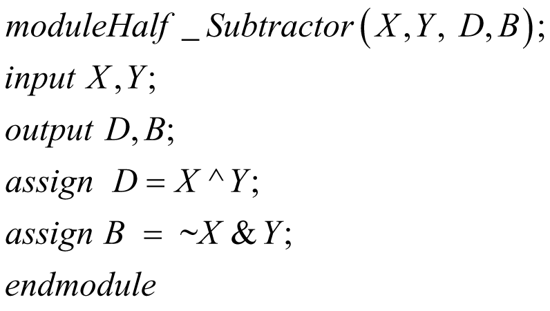
In Verilog code of the half subtractor using dataflow modeling, inputs and outputs are defined inside the module Half_Subtractor. Inside the module, continuous assignment keyword assign is called two times.
5.3.2 Multiplexer
5.3.2.1 2 × 1 Multiplexer
In the 2 × 1 multiplexer (Figure 5.1), there are two inputs, one select line and one output line. Based on the select line, inputs are reflected in terms of output at the output terminal. As only one select line is present in a 2 × 1 multiplexer, there are two options; 0 and 1.

Figure 5.1 Block diagram of 2 × 1 multiplexer.
As shown in Figure 5.1, when the select line becomes 0, the I0 is reflected at output port Y, and when the select line becomes 1, then I1 is considered as output as shown in Table 5.4.
Table 5.4 4 × 1 multiplexer.
| Select lines | Output | |
|---|---|---|
| S1 | S0 | Y |
| 0 | 0 | I0 |
| 0 | 1 | I1 |
| 1 | 0 | I2 |
| 1 | 1 | I3 |
Based on the observations given in Table 5.3, the Boolean expression for a 2 × 1 multiplexer is defined as follows:
Table 5.3 2 × 1 multiplexer.
| Select | Output |
|---|---|
| S | Y |
| 0 | 10 |
| 1 | 11 |
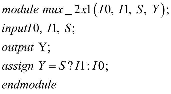
Verilog Code
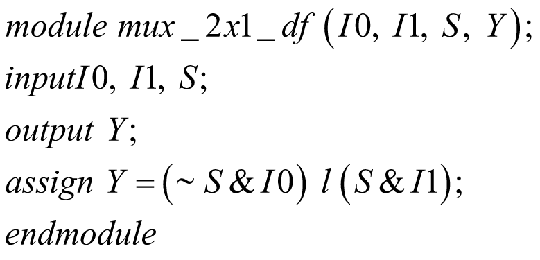
In Verilog code of the 2 × 1 multiplexer using dataflow modeling, inputs and outputs are defined inside the module mux_2x1_df. Inside the module, one continuous assignment keyword assign is used.
5.3.2.1 4 × 1 Multiplexer
In the 4 × 1 multiplexer, there are four inputs, two select lines and one output line. Based on the select lines, the inputs are reflected in terms of output at the output terminal. As only two select lines are present in a 4 × 1 multiplexer (Figure 5.2), there are four options: 00, 01, 10, 11. As shown in Figure 5.2, when the select line becomes 00, the I0 is reflected at the output port Y, and when the select line becomes 11, then I3 is considered as an output [3].
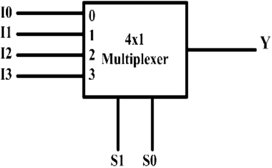
Figure 5.2 Block diagram of 4 × 1 multiplexer.
Based on the observations given in Table 5.4, the Boolean expression for a 4 × 1 multiplexer is defined as follows:

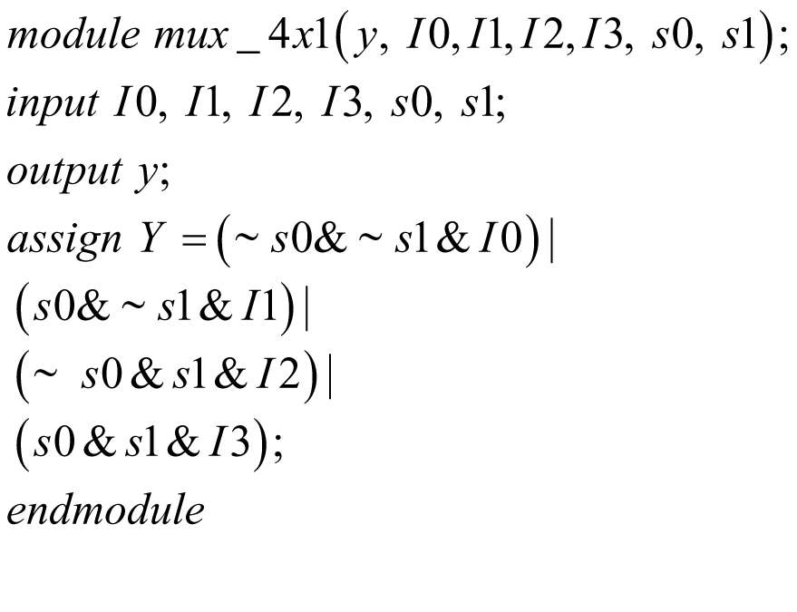
Verilog Code
In Verilog code of a 4 × 1 multiplexer using dataflow modeling, inputs and outputs are defined inside the module mux_4x1. Inside the module, one continuous assignment keyword assign is used according to the Boolean expression (2).
Conditional Operator
A ternary operator is another name for a conditional operator (?:), it uses three operands at a time. When the first is true, the operand at the second is evaluated and when the first is false, the operand at the third is evaluated.
Example of a conditional operator.
assign OUT = select ? A: B;
2 × 1 multiplexer using a Conditional Operator
Based on the observations given in Table 5.5, the Boolean expression for a 2 × 1 multiplexer is defined as follows:
Table 5.5 2 × 1 multiplexer.
| Select line | Output |
|---|---|
| S | Y |
| 0 | I0 |
| 1 | I1 |
Y = S’I0 + SI1.
The conditional operator is used for Y output. The conditional operator (?) suggests output Y is equal to data I1, if the select line S is true otherwise, it is I0 [1].
Verilog Code
In Verilog code of a 2 × 1 multiplexer using a conditional operator, inputs and outputs are defined inside the module mux_2x1. Inside the module, one continuous assignment keyword assign is used. Under the assign statement, a conditional operator is used.
4 × 1 multiplexer using a Conditional Operator:
Based on the observations given in Table 5.6, the Boolean expression for a 4 × 1 multiplexer is defined as follows:

Table 5.6 4 × 1 multiplexer.
| Select lines | Output | |
|---|---|---|
| S1 | S0 | Y |
| 0 | 0 | I0 |
| 0 | 1 | I1 |
| 1 | 0 | I2 |
| 1 | 1 | I3 |
Verilog Code
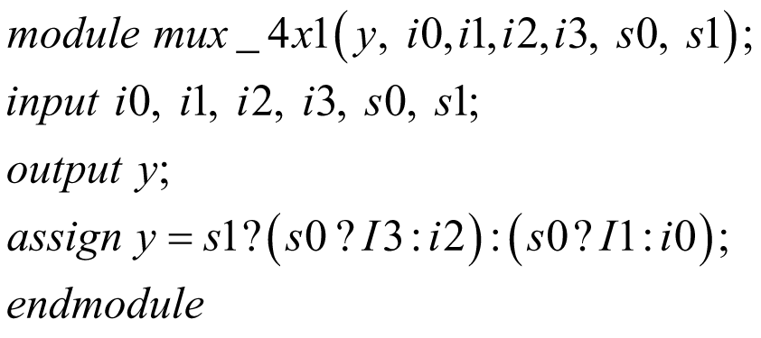
In Verilog code of a 4 × 1 multiplexer using the conditional operator, inputs and outputs are defined inside the module mux_4x1. Inside the module, one continuous assignment keyword assign is used. Under the assign statement, three conditional operators are used according to the Boolean expression.

5.3.3 Decoder
2-to-4 Line Decoder
Based on the observations given in Table 5.7, the Boolean expression for a 2-to-4 decoder is defined as follows:
Table 5.7 2-to-4 decoder.
| Inputs | Outputs | ||||
|---|---|---|---|---|---|
| A | B | D0 | D1 | D2 | D3 |
| 0 | 0 | 1 | 0 | 0 | 0 |
| 0 | 1 | 0 | 1 | 0 | 0 |
| 1 | 0 | 0 | 0 | 1 | 0 |
| 1 | 1 | 0 | 0 | 0 | 1 |
D0 = A’B’
D1 = A’B
D2 = AB’
D3 = AB
Verilog Code
In Verilog code of a 2-to-4 decoder using dataflow modeling, inputs and outputs are defined inside the module Dec_2to4. Inside the module, four continuous assignment keyword assign are used according to the Boolean expression (2).

5.3.4 Comparator
1-bit Magnitude Comparator
A comparator circuit is a combinational circuit that always has three outputs. If two inputs are present in a comparator, three outputs are A < B, A = B, and A > B. In a 1-bit magnitude comparator, two inputs and three outputs are present.
Based on the observations given in Table 5.8, the Boolean expression for a 1-bit comparator is defined as follows:
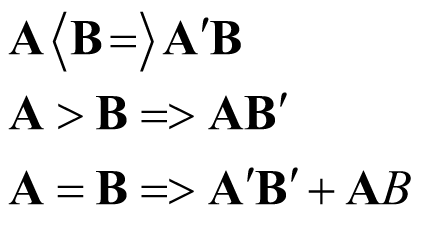
Table 5.8 1-bit magnitude comparator.
| Inputs | Outputs | |||
|---|---|---|---|---|
| A | B | A < B | A = B | A > B |
| 0 | 0 | 0 | 1 | 0 |
| 0 | 1 | 1 | 0 | 0 |
| 1 | 0 | 0 | 0 | 1 |
| 1 | 1 | 0 | 1 | 0 |
Verilog Code:
In Verilog code of the 1-bit magnitude comparator using dataflow modeling, inputs and outputs are defined inside the module Com_1. Inside the module, three continuous assignments keyword assign are used according to the Boolean expressions.

5.4 Testbench
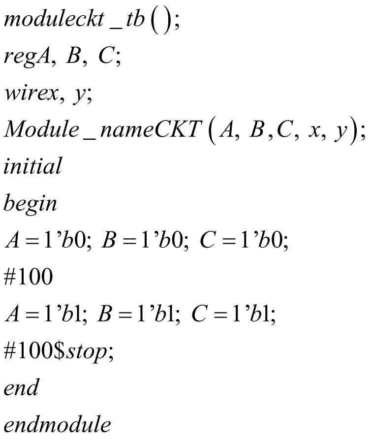
Testbenches are used for simulation purposes. There is no need for physical hardware to design and simulate the testbench. To a Verilog-based design, the testbench defines a sequence of inputs to be applied by the simulator.
The testbench is incorporated into the module to be tested. There is no need for input as well as output nodes for the testbench. The reg and outputs with wire are required to define inputs. The keyword initial is used to define the inputs. All the input values are designated between begin and end [2].
The end of the simulation is determined with $finish or $stop.
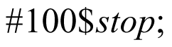
//the simulation will be suspended at time = 100
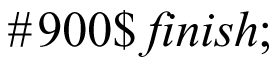
//the simulation will be terminated at time = 1000
Testbench module for a simple circuit
5.4.1 Dataflow Model of the Half Adder and Testbench
In a half-adder circuit, an input port has two inputs A and B whereas the output terminal has two outputs S and C. The main module name of the half adder using dataflow modeling is Half-Add [2]. This main module is called inside the testbench module of half adder HA_tb. Since A and B are defined as input ports in the main module, these two variables are defined as reg in the testbench module. The out port defined in the main module S and C are declared by wire in the testbench module.
//Half adder modulemodule Half_Add(A, B, S, C)input A,B;output S,C;assign S =A^B;assign C =A&B;endmodule
With two input variables four possibilities arise, in testbench all possibilities are given a certain time delay while calling. In the testbench of the half adder illustrated in Box 5.1, 5 ns is used for all four possible states.
5.4.2 Dataflow Model of the Half Subtractor and Testbench
In a half-subtractor circuit, the input port has two inputs X and Y, whereas the output terminal has two outputs, D and B. The main module name of a half subtractor using dataflow modeling is Half_S. This main module is called inside the testbench module of the half subtractor HS_tb. Since X and Y are defined as input ports in the main module, these two variables are defined as reg in the testbench module. The out port defined in the main module as D and B are declared by wire in the testbench module.
//Half Subtractor modulemodule Half_ S(X, Y, D, B);input X,Y;output D,B;assign D=X^Y;assign B=~X&Y;endmodule
With two input variables, four possibilities arise in the testbench, all possibilities are given a certain time delay while calling. In the testbench of the half adder illustrated above in Box 5.2, 5 ns is used for all four possible states.
5.4.3 Dataflow Model of 2 × 1 Mux and Testbench
In the 2 × 1 multiplexer circuit, the input port has two inputs, I0 and I1, along with one select line S, whereas the output terminal has one output Y. The main module name of a 2 × 1 multiplexer using dataflow modeling is mux_2x1_df. This main module is called mux_tb inside the testbench module of a 2 × 1 multiplexer. Since I0, I1, and S are defined as input ports in the main module, these three variables are defined as reg in the testbench module. The output defined in main modules Y, are declared by wire in the testbench module.
//2 × 1 mux module

//2 × 1 mux module with a Conditional operator

5.4.4 Dataflow Model of 4 × 1 Mux and Testbench
In the 4 × 1 multiplexer circuit, the input port has four inputs: I0, I1, I2, and I3, along with two select lines S0 and S1, whereas the output terminal has one output, Y. The main module name of a 4 × 1 multiplexer using dataflow modeling is mux_4x1_df. This main module is called mux_tb inside the testbench module of a 4 × 1 multiplexer. Since I0, I1, I2, I3, and S0, S1 are defined as input ports in the main module, these six variables are defined as reg in the testbench module. The output defined in the main module is Y, which is declared by wire in the testbench module.
//4 × 1 mux module
//4 × 1 mux module with a Conditional operator
5.4.5 Dataflow Model of 2-to-4 Decoder and Testbench
In the 2-to-4 decoder circuit, input port has two inputs A and B whereas the outport has four ports: D0, D1, D2, and D3. The main module name of the 2-to-4 decoder using dataflow modeling is Dec_2to4. This main module is called Dec_tb inside the testbench module of the 2-to-4 decoder. As A and B are defined as input ports in the main module, these two variables are defined as reg in the testbench module. The outputs defined in the main module are D0, D1, D2, and D3; those are declared by wire in the testbench module.
//2-to-4 Decoder modulemodule Dec_2to4(A,B,D0,D1,D2,D3);input A,B;output D0,D1,D2,D3;assign D0=~A&~B;assign D1=~A&B;assign D2=A&~B;assign D3=A&B;endmodule
Review Questions
Q1 Write a Verilog code of a 4-bit full adder using dataflow modeling with testbench.
Q2 Implement a 4-bit adder/subtractor circuit using dataflow modeling of Verilog.
Q3 Design a 8 × 1 multiplexer using the 2 × 1 multiplexer using the dataflow model.
Q4 Write a Verilog code of a 3-to-8 decoder using the dataflow model and illustrate their testbench.
Q5 Write a Verilog code of 2-bit magnitude comparator using the dataflow model.
Multiple Choice Questions
Q1 Which operator is not used as dataflow modeling?
- +
- –
- @
- &
Q2 In the testbench module, the output ports are declared as?
- reg
- wire
- o/p
- i/p
Q3 For the conditional operator, which keyword is used?
- >
- <
- ?
- &
Q4 Which of the following is the continuous assignment keyword?
- module
- assign
- initial
- finish
Q5 Which keyword is used for negation?
- *
- $
- ~
References
- [1] Weste, N.H.E., Harris, D.,, and Banerjee, A. (2004). CMOS VLSI Design: A Circuits and Systems Perspective, 3e. Upper Saddle River, NJ: ed. Pearson.
- [2] Bhaskar, J. (1999). A Verilog HDL Primer. Upper Saddle River, NJ: Pearson.
- [3] Mano, M.M. (1992). Computer System Architecture. Upper Saddle River, NJ: Pearson.