There is an urban myth of an American tourist hiring a car in a foreign land and driving 200 miles in first gear. When the engine eventually overheated and seized up he was asked if did he not suspect somewhere along the journey that something was wrong. He said he thought it was noisy and slow compared to his own car with automatic transmission back home, but having never driven a car with a manual gear change he had no way of comparing the car’s performance.
A basic knowledge of television technology is required to avoid a similar foul-up when new to programme making. Technology is simply a means to an end; the end being a programme that communicates with its audience. Without an understanding of the camera equipment employed or an over-reliance on automatic features, the end result may be less than satisfactory.
In 1888 the Kodak camera was launched as an easy, simple method of taking photographs. ‘You press the button, we do the rest’, was a sales slogan to demystify the arcane process of photography. In the early days of the craft, would-be photographers had to prepare their own glass plates, and then develop them in a combined camera/darkroom. After 1888, anybody could press a button and the camera and the chemist would do the rest. Training in photographic competence was condensed to the few minutes required to be instructed on which button to press.
Over 100 years later, in response to the needs of the TV industry, the craft of camerawork is promoted as a simple matter of knowing the position of a couple of buttons on the camera. After a very short training period, anybody can become a competent television cameraman. If this was true about photography and broadcast camerawork, there should be no visual difference between a holiday snapshot and an advertising brochure of a resort, or a holiday video and a feature film shot at that resort.
Technology and technique intertwine. How you do something in broadcasting depends on what equipment you are using. It is not simply a question of being told which button to press in order to get a professional result. In television camerawork, an understanding of camera technology plus the ability to exploit and take into consideration the attributes of the camera and the lens characteristics is the basis of practical programme production. Most camera equipment is now wrapped up with auto features in the hope of being user-friendly to technophobic customers, but camera operators should aim to understand what is happening when they are using a camera rather than trust the old slogan of ‘you press the button, the equipment will do the rest’.
Simplified figure of a DV camera/recorder
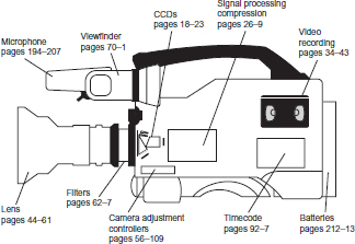
Lens system: The design of the lens affects resolution, image quality, focal length, zoom ratio, exposure and control of zooming. Also important is the lens fitting to allow interchangeability with other lenses.
Charge coupled device: The choice of pick-up sensors (e.g. FIT, HAD, etc.) will determine how light is converted into electricity and will control the quality of image, definition, highlight handling, contrast range and sensitivity.
Television system: How the signal is read from the CCDs will depend on the video system chosen and how it will be seen by its potential audience. Choice of systems range from decisions on colour system (PAL, NTSC, SECAM), line structure (625, 525, 1088, etc.), aspect ratio (4:3 or 16:9), interlace or progressively scanned.
Digital conversion: Choice of sampling rate and how the colour information is sampled will affect how the material is displayed and edited.
Signal processing: How the signal is processed and modified such as knee, linear matrix, gamma will affect the appearance of the final displayed image.
Compression: Digital signals require compression before recording and the compression ratio chosen for the camera and the design and method of compression all affect the signal output.
Video recording format: There are many methods of recording video onto tape or disk (e.g. Betacam SX, DVCPro, DV, Digital-S, etc.). The method and format used in the camera will control the quality of recording and editing format.
Sound: An effective method of recording and monitoring audio levels is needed and the facilities for microphone inputs will affect the final edited audio presentation.
Camera controls: A range of controls are required to achieve a good technical quality image (e.g. white balance, shutter, gain, exposure, menus, set-up cards, built in filters, method of genlocking and monitoring outputs, etc.).
Viewfinder: A quality viewfinder to monitor all aspects of the image output.
Timecode: A method of setting up and recording timecode information on the tape is essential for editing.
Power supplies: Batteries and monitoring the state of charge of batteries is required. Also an input to use an AC adaptor if required.
Pan/tilt head and support system: Adaptor plate on the base of the camera to enable it to be mounted on pan/tilt head and tripod.
Robust mechanical design: A camcorder used for everyday programme production is subjected to much harder wear and tear than a camera used for holidays and family events.
Light reflected from the subject in view will pass through the lens and be focused on the charge-coupled devices fitted in the camera. The effect of the lens and lens characteristics are discussed later. This page details how light is turned into an electrical signal.
How the eye sees colour
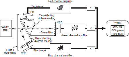
There are many nerve endings in the retina which respond to visible light including red, green and blue receptors which respond to a range of wavelengths. Colours are seen as a mixture of signals from these three types of receptors. Colour television adopts the same principle by using a prism behind the lens to split the light from a scene into three separate channels (see figure opposite).
White balance
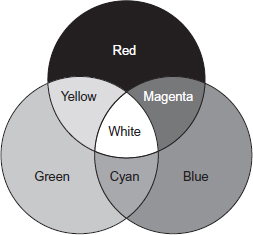
In colorimetry it is convenient to think of white being obtained from equal amounts of red, green and blue light. This concept is continued in colour cameras. When exposed to a white surface (neutral scene), the three signals are matched to the green signal to give equal amounts of red, green and blue. This is known as white balance. The actual amounts of red, green and blue light when white is displayed on a colour tube are in the proportion of 30 per cent red lumens, 59 per cent green lumens and 11 per cent blue lumens. Although the eye adapts if the colour temperature illuminating a white subject alters (see Colour temperature, page 64), there is no adaptation by the camera and the three video amplifiers have to be adjusted to ensure they have unity output.
Colour difference signals
To avoid transmitting three separate red, green and blue signals and therefore trebling the bandwidth required for each TV channel, a method was devised to combine (encode) the colour signals with the luminance signal.
The ability of the eye to see fine detail depends for the most part on differences in luminance in the image and only, to a much smaller extent, on colour detail. This allows the luminance (Y) information to be transmitted at high definition and the colour information at a lower definition resulting in another saving on bandwidth. Two colour difference signals are obtained, Er (red) – Ey (luminance) and Eb (blue) – Ey, by electronically subtracting the luminance signal from the output of the red and blue amplifiers. These two colour signals are coded into the luminance signal (Ey) and transmitted as a single, bandwidth-saving signal. Different solutions on how to modulate the colour information has resulted in each country choosing between one of three systems – NTSC, PAL and SECAM. At the receiver, the signal can be decoded to produce separate red, green, blue and luminance signals necessary for a colour picture. A receiver is a television set that derives its signal from an RF (radio frequency) source (e.g. a transmitter). A monitor is a visual display that is fed with a video signal via a coaxial cable (see Monitor termination, page 17).
Light into electricity
The amplitude of the three individual colour signals depends on the actual colour in the televised scene. Colours are broadband and the light splitting block divides this ‘broad’ spectrum into red, green and blue light to produce three optical images on the respective red, green and blue CCDs. The CCD converts the optical image into an electrical charge pattern. A fourth signal, called the luminance signal, is obtained by combining proportions of the red, green and blue signals. It is this signal which allows compatibility with a monochrome display. The amplitude of the signal at any moment is proportional to the brightness of the particular picture element being scanned.
Additive colour
A composite video signal is an encoded combined colour signal using one of the coding standards – NTSC, PAL or SECAM. This can be achieved using the luminance (Y) signal and the colour difference signals of red minus luminance (Er – Ey) and blue minus luminance (Eb – Ey). The signals are derived from the original red, green and blue sources and this is a form of analogue bandwidth compression.
A component video signal is one in which the luminance and the chrominance remain as separate components, i.e. separate Y, R – Y and B – Y signals.
Television translates light into an electrical signal and then back into light. In its journey from initial acquisition to the viewer’s TV set, the television signal is subjected to adjustments and alterations before it is converted back into a visible image. Like all translations, something is lost along the way and a two-dimensional viewed image can never be an exact visual equivalent of the original. The amount of signal adjustment that occurs in broadcast television is a result of the historical need to ration and allocate transmission bandwidths. These technical restraints set limits to image definition and tonal range. The deliberate subjective creative choices made in creating the programme image also affect the picture viewed by the audience. There are continuing attempts to upgrade the existing various standard TV signals to a higher definition origination and transmission system, but the cost of re-equipping all production and receiving equipment and the lack of agreement on standardization inhibits rapid change.
The technical accuracy of the transmitted image depends on:
■ Time: Human vision cannot instantaneously perceive a complex image and intuitively scans a field of view in order to visually understand what is presented. A video camera requires a mechanism to scan a field of view in a precise, repeated line structure.
■ Detail: The choice of the number of lines and method of scanning is critical to the definition of the captured image and ultimately is dependent on the method chosen to relay the picture to its intended audience. The shape of the screen, the ratio of picture width to picture height, will determine line structure and resolution.
■ Movement: Human perception requires that the repetition rate of each image must exceed approximately 40 pictures per second to avoid flicker and to provide a convincing simulation of smooth movement of any object that changes its position within the frame.
■ Synchronization: The displayed image watched by the viewer must have a mechanism to stay in step with the original scanning of the televised image.
■ Accuracy of the tonal range: Human perception is able to accommodate a wide range of brightness. The television system is only able to replicate a limited range of tonal gradations.
■ Colour: A television electrical signal requires a method of accurately conveying the colour range of the reproduced image. As colour superseded black and white television, the colour system chosen was required to continue to provide compatible pictures for those viewers watching on black and white receivers.
■ Subjective creative choices: The final production images can be customized in an almost limitless way to suit the creative requirements of the programme originator. The line structure and synchronization however remain unaltered.
The television scanning principle
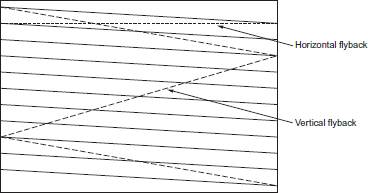
The television picture is made up of a series of lines which are transmitted with synchronizing pulses to ensure that the display monitor scans the same area of the image as the camera. In the PAL 625 line system, each of the 25 frames per second is made up two sets of lines (fields) that interlace and cover different parts of the display. The electrical ‘picture’ is scanned a line at a time and at the end of each line a new line is started at the left-hand side until the bottom of the picture is reached. In the first field the odd lines are scanned after which the beam returns to scan the even lines. The first field (odd lines) begins with a full line and ends on a half line. The second field (even lines) begins with a half line and ends on a full line.
The television waveform
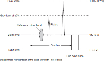
The waveform of the 1 V television signal divides into two parts at black level. Above black, the signal varies depending on the tones in the picture from black (0 V) to peak white (0.7 V). Below black, the signal (which is never seen) is used for synchronizing the start of each line and frame. A reference colour burst provides the receiver with information to allow colour signal processing.
Video images are eventually displayed on a television screen. The quality of the screen, how it has been aligned and adjusted, any reflections or ambient light on the surface of the screen, the size of the screen and the distance at which it is viewed will all affect the quality of the image as seen by the viewer. Some compensation can be built into the video signal to mitigate receiver limitations (see Gamma and linear matrix, page 102), but other factors affecting viewing conditions are outside the control of the programme maker.
Unlike film, where the projected image consists of light reflected from a screen, a television tube emits light. The maximum white it can emit depends on its design and how the display has been adjusted. Black is displayed when there is an absence of any signal, but even when the set is switched off, there is never a true black. The glass front surface of the tube, acting like a mirror, will reflect any images or light falling on the screen degrading ‘black’. These two aspects of the display, its maximum high intensity white and how much ambient light is reflected from its screen set the contrast range that the display will reproduce independent of its received signal.
Resolution
The size of the display screen and its viewing distance will be one factor in how much detail is discernible in a televised image. Due to the regulation of television transmissions, the design of the system (e.g. number of lines, interlace, etc.) and the permitted bandwidth will affect the detail (sharpness) of the broadcast picture. Bandwidth will determine how much fine detail can be transmitted.
The active number of lines (visible on screen) in a 4:3 PAL picture is 575. However, a subject televised that alternated between black and white, 575 times in the vertical direction would not necessarily coincide with the line structure and therefore this detail would not be resolved. The limit of resolution that can be achieved is deduced by applying the Kell factor which for the above example is typically 0.7. This results in a practical resolution of 400 lines/picture height. The horizontal resolution will be 4/3 of 400 equalling 533. The number of cycles of information/line equals 533/2, resulting in 266.5 taking place in 52 μS (time taken per line). This results in a bandwidth requirement of 266.5/52 μS – approximately 5.2 MHz for 625 4:3 picture transmission.
5.2 MHz bandwidth will be required for each channel broadcast using PAL 625, 4:3 picture origination. Other systems will have different bandwidth requirements such as 1250 HDTV PAL which has twice the resolution and needs 30 MHz. Digital transmission allows some bandwidth reduction using compression (see Compression, page 26).
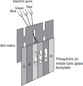
Colour is created on a TV screen by bombarding three different phosphors (red, green and blue) that glow when energized by an electronic beam. The screen may be one of three designs, shadow mask, aperture grill or slot-mask (illustrated above), depending on how the pattern of phosphor dots are arranged on the inside face of the tube. The slot-matrix vertical slots are arranged so that each beam only strikes its corresponding phosphor line on the screen.
NB: a video monitor refers to a visual display fed with a video signal. A receiver refers to a display fed with a radio frequency signal.
Monitor termination
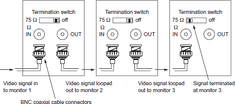
A video signal fed to a monitor must always be terminated (usual value is 75 Ω) unless it is looped through to another monitor. The last monitor in the chain (monitor 3 above) must be terminated to avoid signal distortion.
MOS capacitors
A MOS capacitor (see figure opposite) is a sandwich of a metal electrode insulated by a film of silicon dioxide from a layer of P-type silicon. If a positive voltage is applied to the metal electrode, a low energy well is created close to the interface between the silicon dioxide and the silicon. Any free electrons will be attracted to this well and stored. They can then be moved on to an adjacent cell if a deeper depletion region is created there. The ability to store a charge is fundamental to the operation of the charge-coupled device plus a method of transferring the charge.
Charge-coupled device
If a photosensor replaces the top metal electrode, and each picture element (abbreviated to pixel) is grouped to form a large array as the imaging device behind a prism block and lens, we have the basic structure of a CCD camera. Each pixel (between 500 and 800 per picture line) will develop a charge in proportion to the brightness of that part of the image focused onto it. A method is then required to read out the different charges of each of the half a million or so pixels in a scanning order matching the line and frame structure of the originating TV picture. Currently there are three types of sensors in use differing in the position of their storage area and the method of transfer; they are frame transfer, interline transfer and frame interline transfer (see page 20).
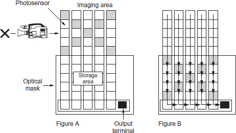
■ Frame transfer: The first method of transfer developed was the frame transfer (FT) structure. The silicon chip containing the imaging area of pixels is split into two parts (see figure opposite). One half is the array of photosensors exposed to the image produced by the lens and a duplicate set of sensors (for charge storage) is masked so that no light (and therefore no build up of charge) can affect it. A charge pattern is created in each picture field which is then rapidly passed vertically to the storage area during vertical blanking. Because the individual pixel charges are passed through other pixels a mechanical shutter is required to cut the light off from the lens during the transfer. An important requirement for all types of CCDs is that the noise produced by each sensor must be equivalent, otherwise patterns of noise may be discernible in the darker areas of the picture.
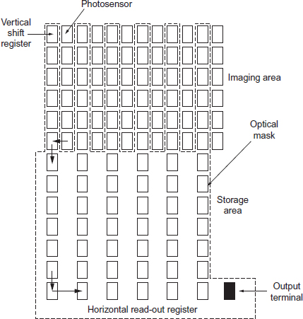
■ Interline transfer: To eliminate the need for a mechanical shutter, interline transfer (IT) was developed. With this method, the storage cell was placed adjacent to the pick-up pixel (see figure on page 21), so that during field blanking the charge generated in the photosensor is shifted sideways into the corresponding storage element. The performance of the two types of cell (photosensor and storage) can be optimized for their specific function although there is a reduction in sensitivity because a proportion of the pick-up area forms part of the storage area.
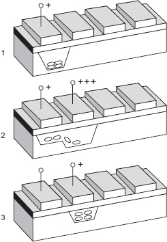
1: After a positive voltage (e.g. 5 V) is applied to the electrode, a low-energy well is created below the oxide/semiconductor surface, attracting free electrons.
2: If 10 V is applied to the adjacent electrode, a deeper low-energy well is created, attracting free electrons which now flow into this deeper bucket.
3: If the voltage on the first electrode is removed and the second electrode voltage is reduced to 5 V, the process can be repeated with the third cell. The charge can be moved along a line of capacitors by a chain of pulses (called a transfer clock) applied to the electrodes.
By replacing the electrode with a light-sensitive substance called a ‘photosensor’, a charge proportional to the incident light is transferred using the above technique.
Schematic of frame transfer CCD
The imaging area of a frame transfer CCD is exposed to the subject (X) and each photosensor is charged in proportion to the incident light intensity. A mechanical shutter covers the photosensors during vertical blanking and each photosensor transfers its charge to the sensor below until the storage area duplicates the imaging area. The shutter is opened for the next field whilst each sensor in the storage area is horizontally read out in turn. What was a two-dimensional grid of variations in light intensity has been converted into a series of voltage variations.
Vertical smear
One problem with interline transfer is vertical smear. This occurs when a very strong highlight is in the picture and results in a vertical line running through the highlight. It is caused by the light penetrating very deeply into the semiconductor structure and leaking directly into the vertical shift register. Since only longer wavelength light is able to penetrate deeply into the silicon, the vertical smear appears as a red or a pink line.
Frame interline transfer
In an attempt to eliminate the vertical smear the frame interline transfer (FIT) was developed (see figure opposite). This combines the interline method of transferring the charge horizontally to an adjacent storage cell but then moves the charge down vertically at 60 times line rate into a frame store area. The charge is therefore only corrupted for a sixtieth of the time compared to IT CCDs.
Resolution
To reproduce fine detail accurately a large number of pixels are needed. Increasing the number of picture elements in a 2/3-in pick-up device results in smaller pixel size which decreases sensitivity.
Aliasing
Each pixel ‘samples’ a portion of a continuous image to produce a facsimile of scene brightness. This is similar to analogue-to-digital conversion and is subject to the mathematical rules established by Nyquist which states that if the input signal is to be reproduced faithfully it must be sampled at a frequency which is greater than twice the maximum input frequency. Aliasing, which shows up as a moiré patterning particularly on moving subjects, is caused by a high input frequency causing a low ‘beat’ frequency. It is suppressed by offsetting the green CCD by half a pixel compared to red and blue. Another technique is to place an optical low pass filter in the light path to reduce the amount of fine detail present in the incoming light.
HAD
The hole accumulated diode (HAD) sensor allows up to 750 pixels per line with an improvement in the photosensing area of the total pickup (see figure on page 23). Increasing the proportion of the surface of the photosensor that can collect light improves sensitivity without decreasing resolution. The HAD chip also helps to avoid vertical smear. Hyper HAD chips increase the sensitivity of cameras by positioning a tiny condensing lens on each individual pixel. This increases the collecting area of light.

Frame interline transfer
Switched output integration
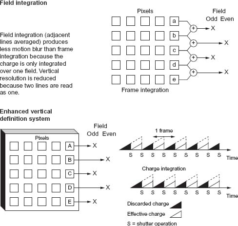
A PAL television picture is composed of 625 interlaced lines. In a tube camera, the odd lines are scanned first then the beam returns to the top of the frame to scan the even lines. It requires two of these fields to produce a complete picture (frame) and to synchronize with the mains frequency of 50 Hz, the picture or frame is repeated 25 times a second.
CCD frame transfer (FT) devices use the same pixels for both odd and even fields whereas interline transfer (IT) and frame interline transfer (FIT) CCDs use separate pixels with a consequent increase in resolution. There are two methods to read out the stored charge:
■ Field integration: This reads out every pixel but the signals from adjacent lines are averaged. Although this decreases vertical resolution, motion-blur will be less.
■ Frame integration: This reads out once every frame (two fields) and therefore will have more motion-blur as the signal is averaged over a longer time span than field integration but may have better vertical resolution on static subjects. Enhanced vertical definition systems offer a higher resolution of frame integration without the same motion blur. It is obtained by blanking off one field with the electronic shutter, reducing camera sensitivity by one stop.
Colorimetry
The transparent polysilicon covering the photosensor of the IT chip progressively filters out the shorter blue wavelength and therefore is less sensitive to the blue end of the spectrum compared to its red response. On HAD sensors there is no polysilicon layer and therefore the spectral response is more uniform.
Flare
Each element in a zoom lens is coated to reduce surface reflections but stray light reaching the prism causes flare, lightening the blacks, and a consequent reduction in contrast of the optical image. Flare is to some extent a linear effect and can be compensated for electronically. Flare can also occur at the surface of CCD devices where light is reflected between layers or scattered by the etched edges of sensor windows.
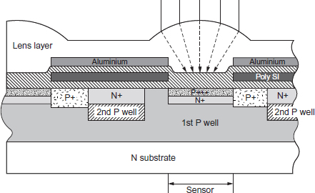
The Hyper HAD has a microlens positioned on each pixel which increases the light-capturing ability of each photosensor area, doubling the camera sensitivity.
Television broadcasting was originated and developed using an analogue signal – a continuous voltage or frequency varying in time. Over the years, engineering techniques overcame many problems associated with this method but there was a limit to what could be achieved. The analogue signal can suffer degradation during processing through the signal chain, particularly in multi-generation editing where impairment to the signal is cumulative. Digital video is an alternative method of carrying a video signal. By coding the video signal into a digital form, a stream of numbers is produced which change sufficiently often to mimic the analogue continuous signal (see figure opposite).
The digital signal
Whereas an analogue signal is an unbroken voltage variation, a pulse coded modulated (PCM) digital signal is a series of numbers each representing the analogue signal voltage at a specific moment in time. The number of times the analogue signal is measured is called the sampling rate or sampling frequency. The value of each measured voltage is converted to a whole number by a process called quantizing. These series of whole numbers are recorded or transmitted rather than the waveform itself. The advantage of using whole numbers is they are not prone to drift and the original information in whole numbers is better able to resist unwanted change. The method of quantizing to whole numbers will have an effect on the accuracy of the conversion of the analogue signal to digital. Any sampling rate which is high enough could be used for video, but it is common to make the sampling rate a whole number of the line rate allowing samples to be taken in the same place on every line.
A monochrome digital image would consist of a rectangular array of sampled points of brightness stored as a number. These points are known as picture cells or more usually abbreviated to pixels. The closer the pixels are together, the greater the resolution and the more continuous the image will appear. The greater the number of pixels the greater the amount of data that will need to be stored with a corresponding increase in cost. A typical 625/50 frame consists of over a third of a million pixels. A colour image will require three separate values for each pixel representing brightness, hue and saturation for each individual sampled point of the image. These three values can represent red, green and blue elements or colour difference values of luminance, red minus luminance and blue minus luminance. A moving image will require the three values of each pixel to be updated continuously.
Advantages of the digital signal
When a digital recording is copied, the same numbers appear on the copy. It is not a dub, it is a clone. As the copy is indistinguishable from the original there is no generation loss. Digital TV allows an easy interface with computers and becomes a branch of data processing.
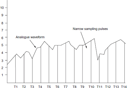
The continuously varying voltage of the TV signal (the analogue signal) is measured (or sampled) at a set number of positions per television line and converted into a stream of numbers (the digital signal) which alters in magnitude in proportion to the original signal.
Storing the signal as binary numbers (ones and zeros) has two advantages. It provides a robust signal that is resistant to noise and distortion and can be restored to its original condition whenever required. Second, it enables computer techniques to be applied to the video signal creating numerous opportunities for picture manipulation and to re-order the digital samples for standards conversion.
Binary counting
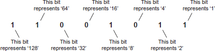
In this 8-bit word called a byte (abbreviated from ‘by eight’) each bit position in the word determines its decimal equivalent. This binary number’s decimal equivalent (reading from left to right) is 128 + 64 + 0 + 0 + 8 + 0 + 2 + 1 = 203.
A 4-bit word has 16 combinations
An 8-bit word has 256 combinations
A 10-bit word has 1024 combinations
A kilobyte (1 Kbyte) of memory contains 1024 bytes
A megabyte (1 Mbyte) contains 1024 kilobytes
A gigabyte contains 1024 megabytes
Digital television has many advantages compared to the older analogue system. Equipment is generally cheaper and error correction can compensate for signal degradation introduced along the signal path. As digital television deals only with ones and zeros, circuits do not require the sophistication needed to maintain the quality of the continuously varying voltage of the analogue signal. But working on the principle that there are never any free lunches, digital signal routing and storage is required to handle very large packets of data and this does pose certain problems. For 625 line, 4:3 PAL TV, the active picture is: 720 pixels (Y) + 360 pixels (Cr) + 360 pixels (Cb) = 1440 pixels per line. 576 active lines per picture means 1440 pixels/line × 576 = 829,440 pixels per picture. Sampling at 8 bits, the picture takes 829,440 bytes, or 830 Kbytes, of storage. One second of pictures would require 830 × 25 = 20,750 Kbytes, or 21 Mbytes. Both 625 and 525 line systems require approximately the same amount of storage for a given time. One minute requires 1.26 Gbytes and 1 hour requires 76 Gbytes. Standard video tape capacity can record only a few minutes of material at this density.
Compression
To reduce the large amounts of data digital television generates, a technique was introduced that looked at each video frame and only passed on the difference between successive frames. With this method of coding it is possible to discard a large percentage of information yet still deliver acceptable TV pictures. The original data rate can be compressed to fit the recording storage capability or to reduce the bandwidth needed for transmission. By eliminating selected data, the signal can be passed through a channel that has a lower bit rate. The ratio between the source and the channel bit rates is called the compression factor. At the receiving end of the channel an expander or decoder will attempt to restore the compressed signal to near its original range of values. A compressor is designed to recognize and pass on the useful part of the input signal known as the entropy. The remaining part of the input signal is called the redundancy. It is redundant because the filtered-out information can be predicted from what has already been received by the decoder. If the decoder cannot reconstruct the withheld data, then the signal is incomplete and the compression has degraded the original signal. This may or may not be acceptable when viewing the received image. Portions of an image may contain elements that are unchanging from frame to frame. Considerable saving in the amount of data transmitted can be achieved if, on a shot change, all of the image is transmitted and then with each successive frame only that which alters from frame to frame is transmitted. The image can then be reconstructed by the decoder by adding the changing elements of the image to the static or unvarying parts of the image. The degree of compression cannot be so severe that information is lost.
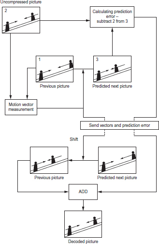
A picture of a passenger travelling on an up escalator is shot with the camera travelling at the same speed as the passenger (2). The only movement in the frame is another passenger travelling on the down escalator. Motion compensation compression attempts to make movement information ‘redundant’ by measuring successive areas of pictures which contain movement and producing motion vectors. These are applied to the object and its predicted new position (3) reconstructed. Any errors are eliminated by comparing the reconstructed movement with the actual movement of the original image. The coder sends the motion vectors and the discrepancies along the channel to the decoder which shifts the previous picture by the vectors and adds the discrepancies to reproduce the next picture. This allows a saving in the amount of data that needs to be transmitted along a channel, even with movement.
Providing only the difference between one picture and the next means that at any instant in time, an image can only be reconstructed by reference to a previous ‘complete’ picture. Editing such compressed pictures can only occur on a complete frame. If there is significant movement in the frame there will be very little redundancy and therefore very little compression possible.
Gains
The main benefits of compressing digital material include:
■ a smaller quantity of storage is required for a given quantity of source material;
■ digital compression reduces the required bandwidth in terrestrial, satellite and cable transmission and allows cheaper use of data transport (e.g. SNG links), interactive services, etc.
4:2:2
A common sampling rate for 625/50 and 525/60 video is chosen to be locked to the horizontal sync pulses. For the luminance signal this is often 13.5 MHz. Only the active lines (576 lines in the 625 system) are transmitted or recorded. Each line consists of 720 pixels. The 49 field blanking lines are ignored and recreated when required.
In many digital formats the colour difference signals have one half the luminance bandwidth and are sampled at half the luminance sample rate of 13.5 MHz (i.e. 6.75 MHz). The lowest practicable sampling rate is 3.375 MHz – a quarter of the luminance rate and identified as 1. Using this code convention:
1 = 3.375 MHz sample rate (3,375,000 samples per second)
2 = 6.75 MHz sample rate (6,750,000 samples per second)
4 = 13.5 MHz sample rate (13,500,000 samples per second)
Most component production equipment uses 4:2:2 sampling which indicates that 13.5 MHz (4) is the sample rate for luminance, 6.75 MHz (2) is the sample rate for red minus luminance and 6.75 MHz (2) is the sample rate for blue minus luminance. Higher compression can be achieved (e.g. 4:1:1 or 4:2:0 sampling). In general, compression can be expected to impose some form of loss or degradation on the picture, its degree depending on the algorithm used as well as the compression ratio (ratio of the data in the compressed signal to the original version) and the contents of the picture itself. Applying greater and greater degrees of compression (i.e. eliminating more of the original) results in artifacts such as fast-moving subjects ‘pixilating’ or breaking up into moving blocks.
Moving Picture Experts Group (MPEG)
MPEG compiled a set of standards describing a range of bitstreams which decoders must be able to handle. MPEG 1 was an earlier specification that is not adequate for broadcast TV. MPEG 2 recommendations for data compression of moving pictures can be abbreviated to a table containing five profiles ranging from Simple (minimum complexity) to High. Each profile can operate at four resolution levels ranging from 352 × 288 pixel image up to 1920 × 1152 pixels. MPEG 2 is not a decoder technique or a method of transmitting bitstreams but a series of benchmarks specifying different degrees of compression.
MPEG 2 interframe compression achieves data reduction by grouping a number of pictures together identified as a GOP (group of pictures). When the MPEG compression process begins, an initial I (intraframe or intrapicture) is coded. This frame is complete and uncompressed and can be displayed without degradation. In the group of pictures associated with this I frame are P (predicted) frames which are based on the I frame and cannot exist without the I frame. Interleaved between the I frame and the P frames are B (Bi-directional) frames which are assembled from interpolated data from the closest I and P frames. A new I frame is usually created in response to a change of pixels in the incoming frames although this can occur without change every approximately half second. Compression is achieved because only the I frames require data to be forwarded.
Because only I frames carry complete picture information, an edit point that occurs between a P and a B frame will start with a frame that cannot reconstruct itself as its reference I frame is missing. It is desirable for efficient compression to have the longest practical group of pictures before a new I frame is included whereas flexibility in deciding which frame to cut on requires the smallest practical GOP and still achieves some degree of compression. Dynamic random access memory (DRAM) chip sets perform I, P and B frame searches to identify an I frame edit.
Concatenation
Along the signal path from acquisition, up and down links, format change, editing and then transmission a video signal can be coded and decoded several times. There are many different types of data compression. Degradation of the digital signal can occur if it is repeatedly coded and decoded whilst passing through two or three different manufacturer’s processors.
Metadata
Metadata is the data that goes along with video and audio as it is networked digitally. Each clip can carry with it detail of where and when it was shot, what format it was in, how it has been processed or compressed, who has the rights to it, when and where it has been transmitted, and any other information that might be needed. This information can be downloaded into an archive database to allow indexing and searches.
A very basic specification for a digital camera suitable for general programme production could include:
■ the ability to interchange the lens (designed for manual focusing/zoom as well as the option of servo control);
■ a camera that allows manual adjustment of a number of facilities (e.g. white balance, timecode, audio level, shutter speed) as well as the option of auto control;
■ a digital recording format with 4:2:2 video sampling plus audio and timecode tracks.
Essentially all three, lens, camera and recorder components, need to be of broadcast quality (see below), but in addition to their engineering specification, they must have the operational facilities required to cover a range of production techniques from initial acquisition to edited master.
Broadcast quality
What is ‘broadcast quality’ will ultimately depend on the broadcaster. Digital acquisition and recording allows variation in sampling (see page 28) and a range of compression ratios. Year on year, technological innovation provides new recording formats. Some, such as the mini DV format, were initially designed for the consumer market but are often used in programme making. A minimum quality benchmark is generally agreed to be 4:2:2 sampling, basically because it allows more flexibility in post-production compositing. But the variety of compression systems introduced into the programme chain also has a significant effect on the final picture quality.
It has always been notoriously difficult to achieve standardization of operational features between different makes of broadcast camera. A simple mechanical device such as the tripod adaptor plate needed to mount the camera/recorder on a pan and tilt head appears to exist in as many versions as there are camera manufacturers. From a cameraman’s point of view, how the production peripherals of a new camera design (batteries, lens, etc.) dovetail with existing equipment is an important practical (and economic) consideration. Broadcast quality can also mean compatible with standard production techniques and facilities.
One-piece camera/recorders have always been available but two-piece camera/recorders allow the user a choice of which recording format to attach to the camera. In the interests of speed and convenience, many organizations need to acquire and edit all production material on the same format coupled with the need for universal technical back-up support for crews working a long way from base. There is continuous market demand for cheaper, broadcast-quality, non-linear editing, especially in news and magazine programme production. This is combined with the development of multi-skilling in acquisition and editing and the pressure to find solutions to edit video material at journalist work stations.
Digital cameras are either combined camera/recorder or the camera section can be interchanged to work with most formats. For standard broadcast camerawork a camera should be capable of manual exposure, focus, white balance and manual control of audio with standard XLR audio inputs. Timecode is essential for logging and editing. Choosing a format depends on programme type and where the production will be seen.
Because of the expansion of recording formats and the many hundreds of camera models available, it is not possible to provide a specific guide to the many variations of operational controls to be found. In general, whatever make of camera or individual model, most broadcast cameras have similar facilities. There is a core of camera controls that are standard on nearly every broadcast quality camera (see pages 56–109). What may change from camera to camera is the positioning of individual operational controls.
| Camera | Lens/lenses + lens cleaning |
| Camera accessories | Tape, matte box and filters; good pan/tilt head and tripod; batteries and portable chargers; mains adaptor; repeat timecode reader. |
| Audio | If working in stereo, a sub-mixer and sufficient selection of microphones, radio mics, mic supports, etc. for the subject. |
| Lighting | At least a ‘flight kit’ – 2/3 lightweight lamps, filter and diffuser material, reflector board. The more complex the shoot, the more lighting equipment may be needed. |
| Transport | For everything you need to take to a location. Easy to underestimate how much this will be. |
General production overview
During acquisition
■ Log all shots.
■ Transfer the material from camera to VHS to review.
■ Have the digital material transferred at a post-production house to VHS with burnt in timecode for off-line editing.
Off-line editing
Check that the editing software you intend to use to produce an EDL (edit decision list; the off-line edit decisions are recorded on a floppy disk giving the tape source of the shot and its in and out timecode or duration. In order to work across a range of equipment there are some widely adopted standards such as CMX, Sony, SMPTE, and Avid) is compatible with the post-production facility where the material will be conformed.
In drama there is always the need for post-production audio. Make certain that the right quality (and sound quality continuity) has been recorded on location. Sound dubbing is needed to add effects, music and additional looped dialogue if original audio is of poor quality.
Many high-end digital cameras have scene files. These are microchips that are inserted into the camera to configure the image to provide a particular ‘look’. Some hire companies have a range of these.
In the mid-1990s, the demarcation between broadcast-quality and consumer cameras was eroded. Some camera formats which had been initially marketed for domestic use were pressed into service for documentary and news production. Not all of these new range of cameras provided for the standard requirements of broadcast camerawork. They often required modification before being suitable for programme production.
Digital technology and de-regulation produced a proliferation of broadcast channels and an escalation in the competition for viewers. The expansion of services created a need to find ways of cutting costs and reducing programme budgets. This also followed the production fashion for less intrusive shooting techniques and the use of small cameras for the coverage of documentary and news. All these changes resulted in the development of digital video recording formats and cameras which were small, cheap (relative to previous broadcast ‘quality’ cameras) and easy to operate.
Button pressing
In the rush to market the new recording formats, the ability to produce a technically acceptable image from a video camera often became confused with the craft of camerawork. Marketing hype suggested that anyone could be a ‘cameraman’ once they understood the automatic features of the new compact video camera. But broadcast camerawork is not simply producing technically competent pictures. Communication with images requires the same understanding of visual conventions and visual potentials as the understanding of language, structure and vocabulary is needed when communicating with words. The ability to assess a well-framed picture and the knowledge of the techniques available to achieve this follows on from the ability to manipulate the camera controls.
Economic choice
The development of journalist computer workstations and the trend towards a ‘tapeless’ newsroom highlighted the problems of back libraries and archive material on a different format to the current operation. There was also the cost to an organization in choosing to have a different format for its news operation than it had for its normal programme acquisition. The economic gain in time saved in acquisition in one format could be outweighed by the cost/time of dubbing across other formats for editing or transmission plus the cost of duplicating a range of postproduction equipment able to handle the different formats. But ranged against these considerations were the savings in camera and tape costs and the potential for lap-top editing systems on location when using the smaller digital recording formats. Some recording formats were conceived chiefly as an acquisition option and were not (in the first instance) intended for general use in broadcasting.
One of 12 tracks that make up one frame of D-9 (625/50 system).

There many different sectors found on each digital recording track (see figure above). There are sectors for video, audio (sometimes as many as 8) and subcode (which contains the digitized timecode). However, the first sector on the tape is usually the ITI sector. The ITI area (or sector) contains useful data needed by the digital recording system, to order the digital blocks of video and audio in their correct position. The ITI track contains an identifier which states if the recording is an SP (Standard Play) or LP (Long Play) type recording. For the moment all recordings made by standard DV format decks are signified as SP, with LP being a future option (but not on professional formats such as DVCPro, DVCam or D-9). When played back by the replay heads, the ITI sector has a number of different sections in it. After a brief pre-amble section, the SSA (Start Sync block Area) section starts. This is a fixed number of bits or ‘blocks’ of data. These are recognizable by their unique but repetitive coding sequence of 0s and 1s. Once recognized these allow the VTR to start a counter which then counts each ‘block’ of data as it is read off the tape during replay. Using this method the VTR can predict where each sector (video, audio or subcode) of the track is physically on the tape, so that accurate insert editing can take place without danger of accidentally overwriting the wrong sector on the tape (see also page 35).
Because all of the VTR systems are mechanical devices with the usual mechanical accuracies, each sector on the tape has a ‘pre-amble’ and ‘post-amble’ section before and after the sector data, which act as a ‘landing and take off zone’ during insert editing by the flying erase and/or record heads. All digital VTRs use a ‘segmented’ recording technique, where there is no longer one track per frame, but as many as 24 tracks per frame (see figure on page 33; D-9 uses 12 in 625 line mode). This gives an additional burden to the tape tracking system as it has to find the correct start track for every frame (track 1), so that this can be read out in time to sit on top of the regenerated syncs on the output. Having located and centred the heads up on a track, there is no guarantee that this is the right track to start with. To help with this problem, the ITI area also contains the track number, which the tracking system can then use in its calculations as to how far the tape-to-head phase must be moved to find the right track (usually by Capstan speed adjustment or TSO – tape speed override).
This system of track identification is also important where only certain tracks within the 12-track frame must be overwritten during insert editing. For instance, in 4-channel recording mode, formats like standard DV and DVCam record audio channel sectors for channels 3 and 4 (as a multiplex) into tracks 7 to 12 of the recorded frame. During insert editing, it becomes necessary therefore to ensure that only those audio sectors on tracks 7 to 12 are re-recorded over, or channels 1 and 2 may be wiped out as well. Note that in D-9, 4-channel recordings are different in that every channel is kept in a separate sector and therefore fully independently editable (without the need for stereo pair lay-offs).
Finally, some digital VTRs use a form of digital tracking which is added to the ITI sector data to ensure that the replay heads stay on track during their sweep across the tape. This is done by using a technique known as 24/25 coding which adds in an extra 0 or 1 after every 3 bytes (24 bits) of data before it is layed down on the tape. By carefully controlling the numbers of 0s and 1s added, the DC content of the replay signal can be modified at relatively low frequencies to produce a sine wave or a pilot tone. As these VTRs use slant azimuth recording techniques, different pilot tone frequencies can be recorded on different tracks. The level of these pilot tones relative to each other can then be assessed on replay, indicating how far off-track the replay head is, with corrections to capstan phase to bring the head back on track. The system works only if there are no head clogs. D-9 does use 24/25 modulation, but it does not use this method of tracking as there is a control track added to the tape for more accurate, reliable and faster tracking control. This is combined with a special digital RF sampling system which ensures that the D-9 always stays on track, even in the event of a severe head clog. The ITI area for digital VTRS is very important although not all of them are called ITI.
Analogue or digital video/audio tape recording requires a moving magnetic tape in contact with a rotating recording/replay head. A rotating recording head allows a higher head-to-tape speed which effectively increases the bandwidth that can be recorded. There are several inherent limitations to perfect reproduction of sound and picture on replay. These include:
■ On recording, tape and head rotation may not be continuously stable and some minute variations in speed may occur. This will affect the accuracy of the recording on replay and adjustment of the replay machine is via a time base corrector which ensures constant replay speed.
■ Although digital signal processing allows a smaller signal-to-noise ratio when recording, it also requires a much higher bandwidth. Some degree of data compression is required.
■ The correct head-to-tape contact is not always maintained due to tape imperfections or a build-up of tape coating or inconsistent tape tension.
Digital recording provides for time compression of the video signal into blocks on recording and an equal and opposite process on replay. This allows track space to be made available for audio. The video and audio signal are recorded in packets of data which are shuffled to assist in error correction. The data is broken up into separate coded blocks and recorded out of sequence to limit the length of missing or corrupted data. On replay, the blocks are decoded and arranged in their correct sequence. The tape is protected in a cassette from dust/dirt contamination to reduce tape/head errors and to allow for easier loading and lacing into a record/replay machine.
Error correction and concealment
Magnetic tape recording suffers from noise and dropouts. A digital signal is composed of binary data and a bit is either correct or wrong. It is a simple matter to correct if an error can be detected. A random error of a single bit on replay can be corrected by either replacing the missing sample with a copy of the preceding sample (although this is only useful for a very few consecutive samples), or replacing it with an average of the preceding and succeeding data.
Dropouts can cause a large number of bits to be missing. Burst error is the loss of a number of consecutive samples when recorded. It is possible to minimize this by arranging the data in a non-sequential order by a controlled code that can be reassembled in its correct temporal order when decoding. This effectively separates the missing data, ensuring that consecutive values are less likely to be lost. Additional correction support is to record duplicate additional data which is redundant if there are no errors but can be used to compare or replace any missing or incorrect data. Error concealment is a process where the value of a missing sample is estimated from those nearby.
In the early 1990s, a consortium of camera manufacturers collaborated on the development of a new, small, digital tape format. The intention was to reach agreement on a single international format. This was achieved with a consumer format which had a compression standard, a mechanism and tape format, a chip set and a standard family of cassettes. Originally intended for the domestic camcorder market, the first generation of DV cameras did not meet the basic ENG requirements of operational features and ruggedness. Later models, intended for the broadcast market, were of much more robust construction, provided XLR audio inputs and operational controls followed the conventional positioning of ENG camera/recorders. They are also equipped with an internal memory system and will not lose timecode settings when the battery is changed. The picture quality is good enough for broadcasters to use the format in productions that required small, inexpensive lightweight kit.
Broadcast operational weaknesses
There are a number of inherent weaknesses if the standard consumer format cameras are used for broadcast production. Apart from the lower specification (see opposite) the cameras are much lighter and extended hand-held work invariably means unsteady camerawork as arms get tired. To overcome unsteady pictures, ‘anti-wobble’ devices or picture stabilizers are fitted, some of which affect picture quality. Most of the cameras have colour viewfinders and sometimes the viewfinder menu allows the colour option to be deselected to aid focusing. There is also the debatable value of an auto-focusing facility. Exposure can be set by auto-exposure or manually although some camera models have no zebra facility. The biggest weakness for broadcast camerawork applications is the sound provision. Apart from the lack of manual adjustment of sound level on some cameras, there is often only provision for a single audio input usually using a mini-jack microphone socket when the conventional broadcast audio input is via XLR sockets.
DV can be edited by transferring straight onto disk for non-linear editing. The initial transfer to another format adds to the editing time but this is often preferred by picture editors because the DV format records sound on the FM tracks combined with the pictures. There is no longitudinal sound track and therefore editors cannot hear the digital sound as they shuttle through the tape. Often there is no timecode regeneration facility on consumer DV and placing a cassette into the camera resets the timecode to zero. This could possibly result in several shots on the same tape having the same timecode. This can be avoided by either recording ‘black and burst’ (continuous timecode and black tape) on tapes prior to use or prior to editing, replacing the original timecode with a continuous edit code for the edit machine. Most DV cameras are designed for occasional domestic use by one careful owner and lack the rugged design necessary for hard ENG usage on location. To overcome some of these production limitations, a ‘professional’ version of the DV format was developed.
DVCPro and DV (consumer) tape formats
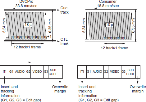
Outline specification of DV and DVCPro
| DV | DVCPro | |
| Video coding | Component digital 13.5 MHz, 8 bit |
Component digital 13.5 MHz, 8 bit |
| Compression | 5:1 intraframe DCT-based standard |
5:1 intraframe DCT-based standard |
| Track layout | 12 tracks/frame 10 microns track pitch |
12 tracks/frame 18 microns track pitch |
| Tape speed | 18.8 mm/s | 33.8 mm/s |
| Tape | 6.35 mm Metal evaporated |
6.35 mm Metal particle |
| Max recording time for cassette | 270 minutes | 123 minutes |
| Video data rate | 24.948 Mbits/s | 24.948 Mbits/s |
| Audio channels | 48 kHz, 16 bits, 2 channel | 48 kHz, 16 bits, 2 channel 1 analogue cue channel |
| Recorded data rate | 41.85 Mbits/s | 41.85 Mbits/s (also 50 Mbps) |
DVCPro and DVCam are upgrades of the DV format originally designed for news acquisition. The two formats have improved recording specifications and a number of broadcast operational facilities not found on consumer DV cameras.
The camera/recorders are smaller, lighter, cheaper, with less power consumption than previous ENG formats, have smaller cassettes and longer recording times. The lightweight cameras allow easier handling in ENG work and have the ability to provide colour playback. With low power consumption, a two-machine editor can provide rapid, portable editing on location and stories can be put to air more quickly.
DVCPro format
A major difference between DVCam and DV is the increase in track pitch from 10 microns to 18 microns which is wider for frame accurate editing on the 6.35 mm/quarter-inch metal particle tape. The first generation of cameras provided for 5:1 DCT compression with 25 Mbps video data rate, 4:1:1 resolution. The maximum tape length allowed 63 minutes of recording on location increased to 123 minutes on studio machines. DVCPro cameras can be obtained with 1/3-, 1/2- and 2/3-inch CCDs and with switchable 4:3/16:9 aspect ratio.
There are two uncompressed audio channels and two longitudinal audio tracks to give audio access when editing as the digital audio is of limited use in shuttle. This linear audio cue channel is also available as a third, lower quality, audio channel.
4:1:1 systems can exhibit errors on chroma edges when applying special effects (e.g. keying, digital effects) or when recording computer generated graphics but there are DVCPro format camera/recorders with 4:2:2 sampling, 3.3:1 DCT compression, a 50 Mbps video data rate using a larger 123 minute (max) cassette recording at twice the tape speed of the 4:1:1 cameras and with interchangeable lenses.
The DV format has auto-tracking mechanisms that eliminate the need for a control track whereas the DVCPro with a control track provides for a faster lock-up and a shorter pre-roll when editing. DVCPro incorporates both VlTC and LTC (see page 92) in the helical scan. This enables the tape size to be kept small and both timecodes to be read at any tape speed. The higher DVCPro specification cameras have 10-bit A/D conversion, 16-bit processing, scene file memory with memory card.
One-frame only (compressed entirely within a single frame) means that the video stream is easily editable, robust and impervious to error propagation. The compression scheme provides a digital structure designed for the special requirements of VTR but it is also suitable for disk-based systems. This allows the interchange of audio and video files between equipment from different manufacturers.
DV-based systems use compression in the most cost-effective way to increase tape usage. DVCam has a 4:1:1 compression, 25 Mbps data rate recorded on metal evaporated tape and 4 channels of uncompressed audio to achieve a 40-minute recording on DVCam camera mini-cassette or 184 minutes on a standard cassette. A single DV compression system is used throughout the production process. Nonlinear editing is facilitated by high speed transfer at four times the normal speed to a disk recorder.
ClipLink

In the transition from analogue to digital acquisition many camera/recorder manufacturers, when introducing new digital formats, have attempted to provide backward compatibility with existing equipment. In many parts of the world, S-VHS has been used not only for ENG purposes but also for a broad range of local broadcasting productions. Digital-S (D-9 format) uses the same size half-inch tape and cassette as S-VHS and records on metal particle tape. Certain Digital-S studio VTRs can replay standard analogue S-VHS tapes allowing continuing access to previous S-VHS tape libraries. Digital-S uses 4:2:2 processing with a video data rate of 50 Mega bits per second with a 3.3:1 compression. The half-inch width tape allows two linear audio cue tracks for audio access in edit shuttle and four digital audio (16 bit, 48 kHz) tracks and two lines for uncompressed video for closed captioning. Up to 104 minutes of material can be recorded.
Digital processing has allowed opportunities to customize more operational controls compared to analogue camerawork. These include:
■ Iris weighting zones: Sections of the image can be selected to have more or less effect in calculating auto-exposure.
■ Detail enhancement: This can be auto adjusted depending on lens angle. A wide-angle shot will have increased detail enhancement.
■ Extended auto-exposure: Exposure is set automatically by adjustment of iris, gain, shutter and ND filter.
■ Smooth transitions: Any large adjustment in auto-exposure/auto white balance values can be smoothly carried out avoiding any obvious ‘jump’ in exposure or colour balance.
■ Black stretch/black compress: This facility operates in a similar way to knee and highlight compression. The transfer characteristic is altered to allow more/less detail to be seen in the darker tones without affecting highlight exposure.
■ Focusing aid: It is easier to check focus when operating on a very narrow depth of field (see page 48). When this focusing aid facility is selected, the lens is set at its widest aperture for a few moments and automatically exposed to allow a check on focus.
■ Variable shutter speed: Shutter speed can be adjusted to the precise rate required (e.g. to avoid flicker when shooting a computer display).
■ Variable detail correction: This facility allows adjustment of contour correction to user requirement.
■ Timecode: Digital timecode is written as data and can be read in still mode as well as fast forward/rewind, unlike analogue recording which required two types of timecode (LTC and VITC) to achieve this.
Depending on recording format and camera manufacture, digital processing also allows a reduction of electronic enhancement on selected skin tones (see page 87). a programmed setting of the linear matrix to allow automatic compensation (e.g. when shooting under fluorescent light), and the ability to store camera settings on scene files.
Digital-S (D-9) tape track format
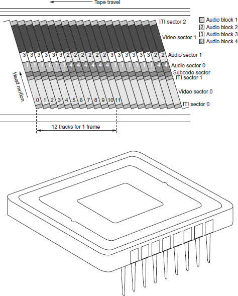
Digital-S interline transfer CCD.
The Camcutter format records direct to disk in the camera/recorder. This allows certain edit functions to be performed in the camera. Whereas the previous digital formats discussed require downloading from tape to disk, the Camcutter’s FieldPak (a disk drive in the camera) can be removed and inserted into the desktop FieldPak adaptor and non-linear edited. Each FieldPak can be re-used many thousands of times. The disk recording unit is available in two configurations: as an add-on to a suitable existing Ikegami camera or as an integrated single-piece camera/recorder unit.
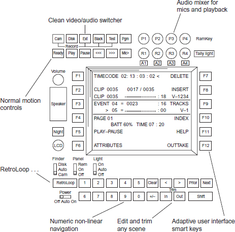
Disk recording allows the following additional production facilities in camera:
■ RetroLoop: This facility constantly records in a pre-defined loop of time selectable from 15 to 60 seconds. When the record button is pressed, video/audio stored in the RetroLoop is kept as part of the new clip. This stored 15–60 seconds of material is added to the new shot.
■ Intelligent recording: This facility allows immediate recording without cueing-up blank tracks even during playback. The new data is written onto free tracks avoiding over-recording previous material. There is automatic clip numbering on every separate shot/recording.
■ Time lapse recording: This function enables intermittent recording at pre-determined intervals for a pre-determined period of time. Disk cameras can be pre-programmed to record one frame at pre-deter-mined intervals.
■ Lip-synching: Audio can be recorded while video is played back. While video is played, a pre-scripted narration can be recorded.
■ Location control: Access to any desired point on the disk can be selected by use of camera report or timecode without the need to shuttle. Simple editing can be done with the camera/recorder.
■ Erasing unwanted video: In camera, previous recordings may be reviewed and unnecessary clips deleted. This function enables only necessary scenes to be left on the disk. About 24–40 minutes (4 Gb) of recording time is normally attainable with a single FieldPak with 6 Gb and 8 Gb units available.
Development with this format has reduced the power consumption and some in-camera editing faculties, although these can still be enabled via a laptop computer.
Random access disk recording: control panel on camera