4.1. Overview of Itanium Instruction Formats
The Itanium architecture specifies 128 general-purpose registers, Gr0 … Gr127, significantly more than most RISC designs. Since 7 bits are required for the 128 different codes for the register identities and since many CPU operations in RISC-like architectures require three register addresses, register addressing alone consumes 21 bits within a hypothetical 32-bit instruction. If the Itanium design had used the prevalent instruction size of 32 bits, only 11 bits would have been left for the opcode and any other requirements in the design of an instruction set.
The trade-off between addressing a large bank of registers and having enough bits for opcode and parameter encoding in the instruction set is clearly pushed to an awkward limit. The next power of two would yield 64-bit instructions with many unused bits. Wider instructions would also mean more bytes to be fetched from memory per unit of useful computing work. Since memory technology is slower than CPU technology, it makes sense to limit instruction width.
Widening the instructions from 4 bytes to 5 might have seemed obvious, yet the design of cache and memory systems argues strongly for clean powers of two. A good clue for a way forward is to recognize that the Alpha and several other architectures fetch 8 or more bytes in the instruction stream, containing two or more instructions. The designers of the Itanium architecture considered schemes where a few instructions would be contained within a span of bytes holding 2x bits, finally choosing x = 7. Early press reports suggested that the 128 bits would represent three 40-bit instructions, leaving 8 bits for other purposes. The final design involves bundles of 41-bit instructions plus 5 extra bits.
4.1.1. Instruction Bundles
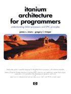
In the final design, Itanium instructions are 41 bits wide and are always fetched as bundles of three, packaged with 5 bits of additional information that instruct the CPU how to decode and execute those three instructions, as shown in Figure 4-1.
Figure 4-1. Itanium instruction bundle format
![]()
Itanium instruction bundles are always aligned in memory on 16-byte addressing boundaries—that is, a bundle has an address whose four lowest-numbered bits are zero (0x...00, 0x...10, 0x...20, etc.). Instruction bundles are always treated as little-endian entities. The three instruction slots within an instruction bundle are filled in order from the sequence of instructions specified by the assembly language programmer or the compiler.
The 5-bit template in each instruction bundle specifies which of 32 predefined patterns describes the instructions in the three slots. The template also specifies whether those three instructions are mutually dependent or whether they may be independently executed, in parallel, along with instructions in the following bundle. We defer any further description of the template and the bundling of instructions until we have first shown how a few individual Itanium instructions work.
4.1.2. Instruction Bit-Field Layouts
The earliest implementations of the Itanium architecture define just over a hundred different layouts, using the 41-bit width of instructions. Those arrangements are fully diagrammed in “Instruction Set Reference,” volume 3 of the Intel Itanium Architecture Software Developer's Manual. While we shall be more interested in the function of Itanium instructions than their binary encoding, getting somewhat acquainted with instruction encoding is an important aspect of learning about computer architecture.
Since the Itanium ISA is a register–register architecture, we would expect that load and store instructions would need at least two operand specifiers, one to select a general register and another to help form a memory address. We would expect that arithmetic and logical unit (ALU) operations, such as addition and OR, would have three operand specifiers: two for sources and one for the destination. A few Itanium instructions need four operand addresses because they require two destinations.
Beyond such considerations, common to most CISC and RISC architectures, the explicit predication of EPIC architecture requires one additional operand specifier for the qualifying predicate that determines whether execution of an instruction has a real effect.
The preceding sketch serves as motivation for expecting—or at least not being entirely surprised—that Itanium instructions must provide up to six main bit-fields. The layout of those fields is shown in Figure 4-2, where the field qp provides for a qualifying predicate, the bit fields labeled field1 to field4 provide space for up to four operands, and the highest four bits specify the major opcode.
Figure 4-2. Itanium instruction bit-field layout
![]()
When fewer operands are needed, many bits may be reinterpreted as opcode extension fields, or as space where useful numeric constants can be incorporated within the instruction itself as immediate data. For a three-operand instruction, field1 designates the destination for whatever manipulation the CPU carries out using two source operands, field2 and field3.
4.1.3. Classes of Itanium Instructions
For both semantic and practical reasons, Itanium instructions fall into several broad classes:
Type A instructions include the classic ALU operations on integers, involving arithmetic operations, Boolean logic operations, and comparison of data values (about 10 different instruction layouts).
Type I instructions include other operations on integers, such as multimedia instructions, bit-shifting to the left or right, and moving information to or from certain special-purpose registers (about 30 different instruction layouts).
Type M instructions include load and store operations for integer and floating-point data, move operations between the general-purpose integer registers and floating-point registers, and the programmer's limited control over memory and cache (about 45 different instruction layouts).
Type B instructions include those for branching, jumping, and calling and returning from functions or procedures (about 10 different instruction layouts).
Type F instructions include modifications and comparisons involving floating-point data (about 15 different instruction layouts).
Type X instructions include a few special instructions where two slots in a bundle are used to encode more than what would fit entirely within 41 bits for an instruction (about 5 different instruction layouts).
This seeming complexity accommodates a versatile RISC-like instruction set augmented by multimedia instructions, instruction-by-instruction predication, and programmer access to special-purpose registers in the processor.
These different types of instructions require, or benefit from, different types of digital circuitry to execute them efficiently. Contemporary architectures of all sorts—CISC, RISC, and EPIC—segregate floating-point from integer operations. The best implementations also distribute integer operations among functional units or execution units that are optimized for calculations, memory access, branch support, or other operations. The resulting implementation is described as superscalar because it can perform several conceptually simple operations simultaneously in the segregated operational units. A processor that is highly superscalar may contain multiple functional units of each specialty.
The earliest Itanium implementations contain four types of execution units that are specialized for integer operations, memory access, branch control, and floating-point operations. Table 4-1 shows how the six instruction types map onto four execution unit types.
We see an expected correspondence between the type I, M, B, and F instructions and the type I, M, B, and F execution units for decoding and completing them. The earliest Itanium implementations do not have any A-units; instead, both the I-units and M-units are designed to execute the highly prevalent type A instructions. Type X instructions, which occupy two slots of an instruction bundle, are executed by either an I- or B-unit, depending on the nature of the operation to be carried out.
Hypothetically, some future implementation of the Itanium architecture might contain one or more A-units to execute type A instructions. The I- and M-units could then possibly be made faster by eliminating some of their present versatility.
If we refer back to the discussion of an instruction cycle (Section 2.2), we may now wonder how the Itanium architecture gets along with only 24 = 16 major opcodes. As already mentioned, a template field occurs within each bundle of three instructions. The binary code in that field specifies which kind of execution unit in the CPU can execute the instruction in each slot in the bundle. When a 41-bit instruction is turned over to a specific execution unit, the major opcode can take on a different meaning for that execution unit than for other types of execution units.
For instance, a major opcode value of 4 means that an instruction given to an M-unit for handling should be further decoded as a load or store operation involving integer registers. The same major opcode value of 4 means that an instruction given to an F-unit for handling should be further decoded to see which of certain comparison operations involving floating-point registers should be carried out. Opcode extension bits found elsewhere in the instruction can then focus the instruction decoding down to one specific operation, and the hardware will control the execution unit accordingly.
| Description of Operation | Instruction Type | Execution Unit Type |
|---|---|---|
| Arithmetic, logic, comparison | A | I-unit or M-unit, whichever is available |
| Non-ALU integer operations | I | I-unit |
| Memory access and Gr/Fr moves | M | M-unit |
| Branches and calls | B | B-unit |
| Floating-point operations | F | F-unit |
| Extended two-slot instructions | X | I-unit or B-unit, depending on operation |
The use of opcode extension bits generally allows for a few principal opcode values to be “reserved” when an architecture is first defined. For early implementations of the Itanium architecture, five of the 16 major opcode values have no meaning to one or another of the various execution units.
Attempting to execute a reserved instruction generally produces a hardware fault that will be intercepted and interpreted by the operating system software. If an architecture is extended to use previously reserved opcodes, the augmentation should be designed as a strict superset of the fundamental architecture. Programs assembled or compiled for the earliest models will run at full speed on later models, while new programs containing the new instructions can at best run slowly on the earlier processor models, and then only if software or firmware emulation of those new instructions is provided.